

Page 1
®®®
Clinical Manual
®
Page 2
TM
Clinical
Manual
Page 3

BiPAP systems are the subject of one or more of U.S. Patents #5148802, #5239995, #5313937,
#5433193, Canadian Patent #2, 024, 477, European Patent #EP0425092, German Patent #69021681.508, and other pending U.S. and foreign patents. BiPAP, Harmony, Plateau, Whisper Swivel, Comfort
Flap, Spectrum, Monarch, Softcap, Quick Clip, Oasis, and Auto-Trak Sensitivity are registered trademarks of Respironics, Inc.
© 2000 Respironics, Inc. All rights reserved.
Page 4

Contents
Chapter 1: Introduction..........................................................................................1-1
1.1 Vision Overview.................................................................................................1-1
1.2 Manual Overview...............................................................................................1-2
1.3 Symbol Key........................................................................................................1-3
1.4 Product Support..................................................................................................1-4
Chapter 2: Warnings, Cautions, and Notes...........................................................2-1
2.1 Warnings.............................................................................................................2-1
2.3 Notes...................................................................................................................2-4
2.2 Cautions..............................................................................................................2-4
2.4 Important Information Concerning CO
2.5 Intended Use.......................................................................................................2-6
2.6 Contraindications ...............................................................................................2-6
2.7 Patient Cautions..................................................................................................2-6
2.8 Invasive Applications ......................................................................................... 2-7
Chapter 3: Principles of Operation........................................................................3-1
3.1 Introduction ........................................................................................................3-1
3.2 Design and Operation.........................................................................................3-2
3.2.1 ELECTRONICS SYSTEM ......................................................................................................... 3-2
3.2.2 O
3.2.3 P
3.2.4 S
3.2.5 F
XYGEN MODULE ............................................................................................................... 3-4
NEUMATIC SYSTEM............................................................................................................. 3-5
TANDBY MODE .................................................................................................................. 3-6
LOW ANALYSIS ..................................................................................................................3-7
3.3 BiPAP® Auto-T rak Sensitivity™........................................................................3-8
3.3.1 LEAK TOLERANCE ............................................................................................................... 3-8
3.3.2 S
ENSITIVITY ........................................................................................................................ 3-9
3.4 Description of System Alarms..........................................................................3-12
3.4.1 CHECK VENTILATOR .......................................................................................................... 3-12
3.4.2 V
3.4.3 E
ENTILATOR INOPERATIVE .................................................................................................. 3-12
XHALATION PORT ALARM .................................................................................................3-12
3.5 User Interface ...................................................................................................3-13
3.6 Exhalation Port Test .........................................................................................3-14
Rebreathing ........................................2-5
2
i
Page 5

Chapter 4: Controls and Displays ..........................................................................4-1
4.1 Overview ............................................................................................................4-1
4.2 Patient Circuit Connections................................................................................4-2
4.3 Adjustment Knob ...............................................................................................4-2
4.4 Soft Keys............................................................................................................4-3
4.4.1 SOFT KEY OPERATION ............................................................................................................4-3
4.4.2 S
OFT KEY DESCRIPTORS ......................................................................................................4-3
4.5 Hard Keys—Operational....................................................................................4-4
4.5.1 MONITORING HARD KEY ..................................................................................................... 4-4
4.5.2 P
4.5.3 M
4.5.4 A
ARAMETERS HARD KEY ..................................................................................................... 4-5
ODE HARD KEY ............................................................................................................... 4-5
LARMS HARD KEY ............................................................................................................4-5
4.6 Hard Keys—Graph Control ...............................................................................4-6
4.6.1 SCALE HARD KEY ............................................................................................................... 4-6
4.6.2 F
REEZE/UNFREEZE HARD KEY .............................................................................................4-6
4.7 Hard Keys—Alarm ............................................................................................4-7
4.7.1 ALARM SILENCE HARD KEY ................................................................................................ 4-7
4.7.2 A
LARM RESET HARD KEY ...................................................................................................4-7
4.8 Ventilator W arning Indicators ............................................................................4-8
4.8.1 VENTILA T OR INOPERATIVE INDICATOR.................................................................................... 4-8
4.8.2 C
HECK VENTILATOR INDICATOR ............................................................................................ 4-8
4.9 Graphic Display..................................................................................................4-9
4.9.1 MODE/MESSAGE AREA ........................................................................................................ 4-9
4.9.2 G
4.9.3 D
4.9.4 D
RAPHIC DISPLAY AREA ...................................................................................................... 4-9
ATA DISPLAY AREA ...........................................................................................................4-9
ATA VALUES ................................................................................................................... 4-10
4.10 Rear Panel ........................................................................................................4-13
4.10.1 POWER ENTRY MODULE ..................................................................................................... 4-13
4.10.2 S
4.10.3 O
4.10.4 D
4.10.5 N
4.10.6 G
TART/STOP SWITCH ..........................................................................................................4-13
XYGEN MODULE ............................................................................................................. 4-14
IAGNOSTIC CONNECTOR ...................................................................................................4-14
URSE CALL/REMOTE ALARM CONNECTOR ......................................................................... 4-14
ROUNDING STUD ............................................................................................................. 4-14
4.11 Internal Alarm Battery......................................................................................4-14
4.12 Parameter Retention .........................................................................................4-14
4.13 Options.............................................................................................................4-15
Chapter 5: Operational Flow Charts.....................................................................5-1
5.1 Start-up Flow Chart............................................................................................5-1
5.2 Change Mode Flow Chart ..................................................................................5-2
5.3 Modify Parameters Flow Chart..........................................................................5-3
5.4 Modify Alarms Flow Chart ................................................................................5-4
ii
Page 6

Chapter 6: Setting Up and Starting the Vision System........................................6-1
6.1 Setting Up the Vision System.............................................................................6-1
6.2 Starting the Vision System .................................................................................6-3
6.3 Changing the Language......................................................................................6-7
Chapter 7: Performance Verification.....................................................................7-1
Chapter 8: CPAP Mode...........................................................................................8-1
8.1 Overview ............................................................................................................8-1
8.2 Changing to the CPAP Mode .............................................................................8-2
8.3 Modifying Parameters in the CPAP Mode .........................................................8-4
8.4 Modifying Alarm Parameters .............................................................................8-6
Chapter 9: S/T Mode ...............................................................................................9-1
9.1 Overview ............................................................................................................9-1
9.2 Changing to the S/T Mode .................................................................................9-3
9.3 Modifying Parameters in the S/T Mode.............................................................9-7
9.4 Modifying Alarm Parameters .............................................................................9-9
Chapter 10: Options Screen..................................................................................10-1
10.1 Overview ..........................................................................................................10-1
10.2 Using the Options Screen.................................................................................10-2
10.2.1 ERROR MESSAGES ............................................................................................................. 10-2
10.2.2 T
10.2.3 D
10.2.4 C
10.2.5 R
10.2.6 A
10.2.7 T
10.2.8 R
ESTING THE ALARMS ........................................................................................................ 10-3
ISPLAYING SYSTEM INFORMATION .....................................................................................10-4
HANGING THE GRAPHIC DISPLAY ......................................................................................10-4
ESETTING THE TIME AT PRESSURE ..................................................................................... 10-5
DJUSTING THE DISPLAY .................................................................................................... 10-5
OTAL OPERATING TIME .................................................................................................... 10-6
ETURNING TO THE MONITORING SCREEN ...........................................................................10-6
Chapter 11: Modifying Graphic Displays ........................................................... 11-1
11.1 Overview .......................................................................................................... 11-1
11.2 Modifying the Display Graph Scales ............................................................... 11-2
11.2.1 MODIFYING THE SCALES .................................................................................................... 11-2
11.2.2 R
ETURNING TO THE MONITORING SCREEN ........................................................................... 11-4
11.3 Summary of Display Graph Scale Ranges and Increments..............................11-4
11.4 Freezing and Unfreezing the Graphs................................................................ 11-5
Chapter 12: Alarms and Troubleshooting...........................................................12-1
12.1 Alarms Overview .............................................................................................12-1
12.1.1 ALARM INDICATIONS .......................................................................................................... 12-2
12.1.2 A
LARM SILENCE AND RESET ..............................................................................................12-2
12.2 Alarms ..............................................................................................................12-3
12.3 Mask Discomfort and Corrective Actions......................................................12-10
iii
Page 7

Chapter 13: Oxygen Delivery with the Vision Ventilator...................................13-1
13.1 Overview ..........................................................................................................13-1
13.2 Oxygen Module ................................................................................................13-2
Chapter 14: Cleaning and Routine Maintenance ...............................................14-1
14.1 Overview ..........................................................................................................14-1
14.2 Cleaning the Vision Unit ..................................................................................14-1
14.2.1 CLEANING THE FRONT PANEL .............................................................................................14-1
14.2.2 C
LEANING THE ENCLOSURE ................................................................................................ 14-1
14.3 Replacing the Inlet Filter ..................................................................................14-1
14.4 Changing the System Fuses..............................................................................14-3
14.5 Voltage Selection..............................................................................................14-3
14.6 Preventive Maintenance ...................................................................................14-3
14.7 Internal Battery Maintenance ...........................................................................14-4
14.7.1 BATTERY FUNCTION ........................................................................................................... 14-4
14.7.2 L
14.7.3 C
OW BATTERY CONDITION .................................................................................................14-4
HARGING THE INTERNAL BATTERY..................................................................................... 14-5
Chapter 15: Accessories ........................................................................................15-1
15.1 Circuit Configurations ......................................................................................15-1
15.1.1 STANDARD NONINVASIVE CIRCUIT ......................................................................................15-2
15.1.2 N
15.1.3 I
ONINVASIVE CIRCUIT WITH HEATED HUMIDIFIER ................................................................ 15-2
NVASIVE CIRCUIT ..............................................................................................................15-3
15.2 Circuits and Accessories...................................................................................15-4
15.3 Exhalation Ports................................................................................................15-4
15.4 Masks and Related Accessories ........................................................................15-4
15.5 Humidifiers.......................................................................................................15-4
Chapter 16: Specifications ....................................................................................16-1
ENVIRONMENTAL ..........................................................................................................................16-1
P
HYSICAL ..................................................................................................................................... 16-1
E
LECTRICAL ................................................................................................................................. 16-1
P
RESSURE .....................................................................................................................................16-1
C
ONTROL ACCURACY .................................................................................................................... 16-2
ISPLAY ACCURACY...................................................................................................................... 16-2
D
T
RIGGER ......................................................................................................................................16-2
O
XYGEN MODULE INLET ...............................................................................................................16-2
I
NTERNAL BATTERIES .................................................................................................................... 16-2
I
NLET FILTER ................................................................................................................................16-2
URSE CALL/REMOTE ALARM CONNECTOR .................................................................................... 16-2
N
C
ONTROL RANGES & INCREMENTS ................................................................................................. 16-3
D
ISPLAY RANGES & INCREMENTS .................................................................................................. 16-4
CO
REBREATHING CHARTS—NON-INVASIVE APPLICATIONS ............................................................ 16-5
2
CO
REBREATHING CHARTS—INVASIVE APPLICATIONS .................................................................... 16-7
2
iv
Page 8
Chapter 1: Introduction
1-1
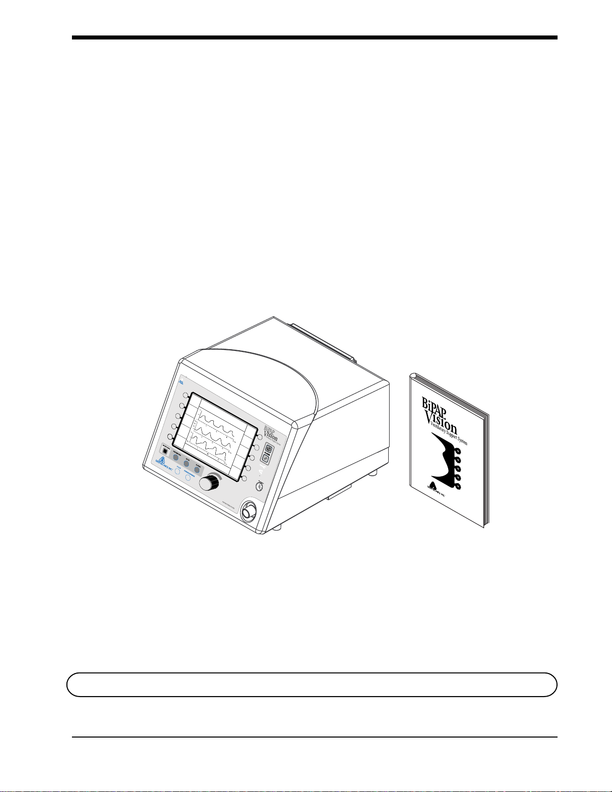
1.1 Vision Overview The BiPAP
controlled positive pressure ventilatory assist system. The Vision system
incorporates a user interface with multifunction keys, real time graphic displays, and integral patient and system alarms. Figure 1-1 shows the contents of
the Vision package.
The system operates in the Continuous Positive Airway Pressure (CPAP) and
Pressure Support (S/T) modes.
The Vision ventilator contains a variety of integrated safety and self-diagnostic
features. All system functions are checked at start-up and during operation.
Pressure regulation is achieved by monitoring proximal airway pressure and
adjusting flows accordingly to ensure that the set pressure equals the proximal
pressure.
®
Vision ventilator, shown in Figure 1-1, is a microprocessor-
EPAP
cm H
Rate
12
BPM
V
T
1000
IPAP
15
cm H
O
2
6
O
2
Vol (ml)
Flow (L/min)
ml
MinVent
MODE: S/T MONITORING
P (cm H
O)
2
PS = 9
%O
2
cm H
2
O
55
%
14
L/min
PIP
15
cm H
O
2
Options
The First Name In Innovative Respiratory Care
Vision Ventilator Vision Clinical Manual
Figure 1-1. Contents of the Vision Package.
Clinical
Manual
NOTE: This manual is for use only in the United States and its territories.
BiPAP Vision Clinical Manual
Page 9

1-2
1.2 Manual Overview
This manual describes the Vision ventilator and its operation.
Chapter 1 Introduces the Vision unit.
Chapter 2 Lists the Warnings, Cautions, Notes and
Contraindications for the Vision ventilator. Also contains
information concerning rebreathing.
Chapter 3 Describes the theory of operation.
Chapter 4 Provides an overview of the output, controls, and
graphic display.
Chapter 5 Provides operational flow charts as an introduction andquick
reference.
Chapter 6 Provides the set up and start-up procedures for the
Vision ventilator.
Chapter 7 Provides the performance verification procedure.
Chapter 8 Details the operation of the CPAP Mode.
Chapter 9 Details the operation of the S/T Mode.
Chapter 10 Details the Options Screen.
Chapter 11 Describes the graphic displays, including modification of
display scales.
Chapter 12 Describes the alarms and alarm conditions and provides
troubleshooting guidelines for mask discomfort.
Chapter 13 Provides information for adding oxygen to the Vision patient
circuit.
Chapter 14 Provides cleaning instructions and routine maintenance
procedures.
Chapter 15 Describes the accessories and circuits to be used with the
Vision ventilator.
Chapter 16 Lists the Vision ventilator specifications.
NOTE: Occasionally, cosmetic changes may be made to the product that do not affect the performance or
specifications of the product. These kinds of changes do not warrant a reprinting of this manual.
Illustrations are for reference only.
BiPAP Vision Clinical Manual
Page 10
1-3
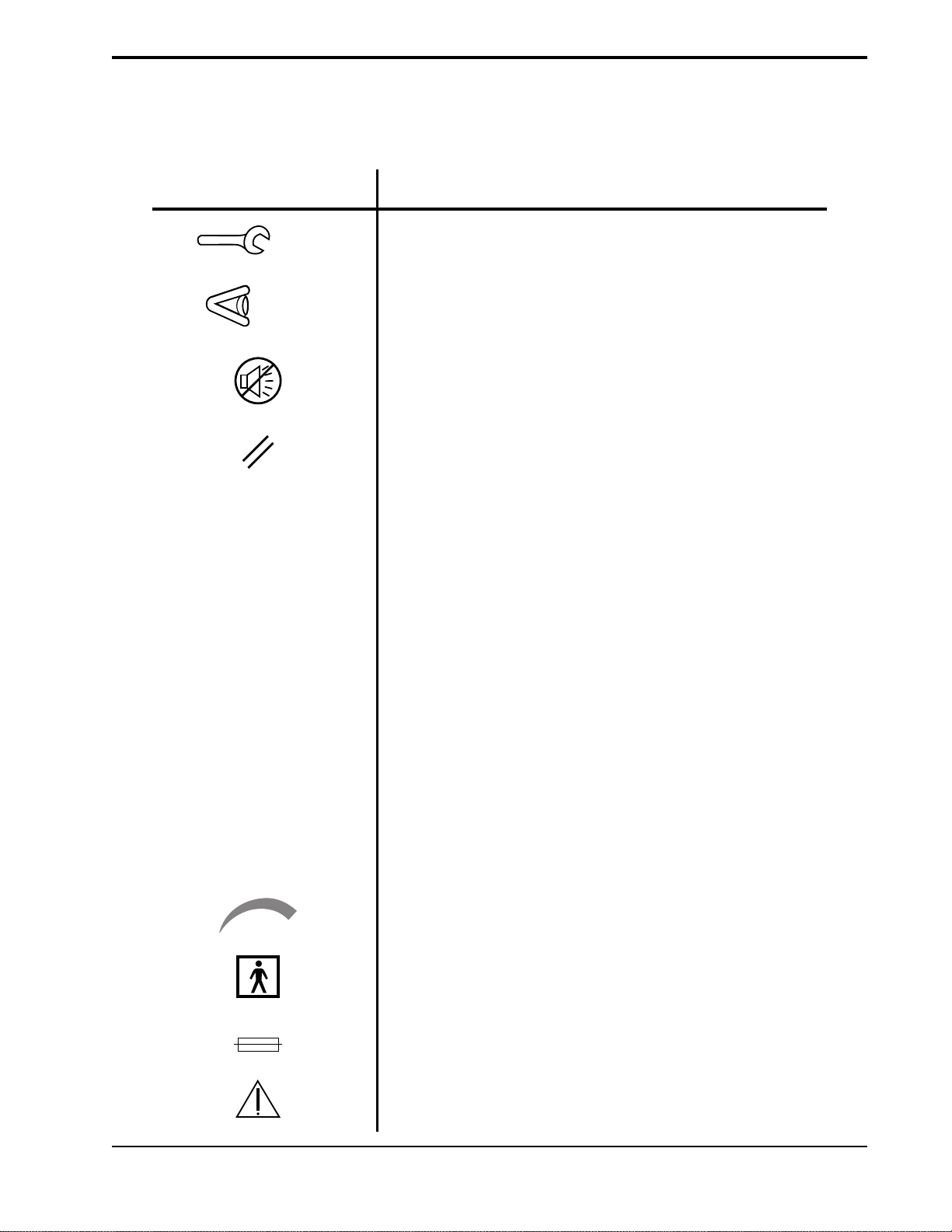
1.3 Symbol Key
Symbol Meaning
MONITORING
Vent Inop
Check Vent
The following symbols are used on the Vision unit:
Ventilator Inoperative
Check Ventilator
Audible Alarm Silence
Alarm Reset
Display the Monitoring Screen
PARAMETERS
ALARMS
SCALE
FREEZE/UNFREEZE
PRESSURE
MAIN POWER
Display the Parameters Screen
Display the Change Alarms Screen
Adjust the graphic scales
Freeze or Unfreeze the graphic display
Attachment port for proximal pressure line
Indicates unit is connected to power source
Adjustment
Type BF
Fuse
Attention, consult
accompanying documents
BiPAP Vision Clinical Manual
Page 11

1-4
1.4 Product Support
You may contact Respironics, Inc. with any questions or for product support at
the following location:
BiPAP Vision Clinical Manual
Page 12

Chapter 2: Warnings, Cautions, and Notes
WARNING: Indicates the possibility of injury to the patient or the operator.
CAUTION: Indicates the possibility of damage to the device.
NOTE: Places emphasis on an operating characteristic.
2-1
2.1 Warnings
• This manual serves as a reference. The instructions in this manual are
not intended to supersede the institution’s protocol regarding the use of
the Vision ventilator.
• The operator must verify that all gas connectors have color codes in
accordance with EN 60601-1/A13:1995.
• The following BiPAP Vision System operational characteristics differ
from conventional ventilators as described in ASTM F 1100 and
should be reviewed before use:
• The BiPAP Vision provides continuous positive airway pressure
(CPAP) and positive pressure ventilation and is indicated for
assisted ventilation. This system does not provide ventilation
with guaranteed tidal volume delivery. Patients requiring
ventilation at predetermined tidal volumes are not candidates for
pressure support or pressure-limited ventilation.
• The BiPAP Vision requires an intentional leak port instead of an
actively controlled exhalation valve to remove exhaled gases
from the circuit. Therefore, specific masks and circuits using an
intentional leak port are required for normal operation. The
pressurized air from the Vision causes a continuous flow of air to
exhaust from the leak port, flushing exhaled gas from the circuit.
The machine should be turned on and the intentional leak port
should be checked, both visually and using the exhalation port
test, before application. Use only Respironics-specified circuit
accessories.
• The continuous flow of air through the leak port flushes exhaled
gases from the circuit. The ability to completely exhaust exhaled
gas from the circuit is dependent upon the EPAP setting and I:E
ratio. At low EPAP pressures or with short expiratory times (i.e.,
high breathing rates) the leak rate through the intentional leak
port may be inadequate to clear all exhaled gas from the circuit.
Some rebreathing may occur.
• The Vision ventilator is an assist ventilator and is intended to augment
the ventilation of a spontaneously breathing patient. It is not intended
to provide the total ventilatory requirements of the patient.
• The Vision ventilator is intended for use with a Respironics, Inc.
patient circuit only. See Chapter 15 for approved patient circuit
configurations and accessories.
BiPAP Vision Clinical Manual
Page 13

2-2
Warnings (continued)
• Proper operation of the Plateau™ Exhalation Valve or any other
exhalation port used with the BiPAP Vision must be regularly verified
by inspection during use. Occlusion or partial occlusion of the
exhalation port may result in asphyxia.
• To reduce the risk of contamination, a low resistance main flow
bacteria filter must be placed in-line between the unit and the patient.
• All patient settings must be determined via appropriate assessment and
monitoring as determined by the prescribing physician. Delivered
pressures must be monitored at the patient connection with the unit
cycling to validate pressure delivery.
• The Vision ventilator is not suitable for use in the presence of a
flammable anesthetic mixture with air or with oxygen or nitrous oxide.
• Oxygen supports combustion. Oxygen should not be used while
smoking or in the presence of an open flame.
• The functionality of this machine may be adversely affected by the
operation of high frequency (diathermy) equipment, defibrillators, or
short wave therapy equipment in the general vicinity.
• When the Oxygen Module is in use, the Vision ventilator will display
the set oxygen concentration, which may not be the actual oxygen
concentration delivered to the patient. An external oxygen analyzer,
added to the patient circuit, is recommended to monitor delivered
oxygen concentrations. See Chapter 13 for details concerning the use
of oxygen with the Vision ventilator.
• When using the Oxygen Module, the operator must verify that the
correct supply gas (O2) is connected to the O2 inlet.
• Do not use antistatic or electrically conductive hoses or tubing with the
Vision system.
• In the event of a power failure, an audible and visual alarm will
activate. Disconnect the Vision ventilator from the patient immediately. As in most ventilators with passive exhalation ports, when
power is lost, sufficient air will not be provided through the circuit and
exhaled air may be rebreathed.
• The air flow for breathing produced by this device can be as much as
10 °F (5.5 °C) higher than room temperature. Caution should be
exercised if the room temperature is greater than 95 °F (35 °C).
• If the “Ventilator Inoperative” indicator illuminates, immediately
discontinue use, disconnect the patient circuit from the patient, and
contact Respironics, Inc. or an authorized service center.
• When the Vision ventilator is used with a humidifier, always position
the humidifier lower than both the ventilator and the patient.
• Never attach oxygen tubing or any positive pressure source to the
Pressure Port on the front panel of the Vision ventilator.
BiPAP Vision Clinical Manual
Page 14

2-3
Warnings (continued)
• If you detect any unexplained changes in the performance or displays
of the Vision unit, seek the assistance of a Respironics-approved
service person.
• Repairs and adjustments must be performed by Respironics-authorized
service personnel ONLY. Service done by inexperienced, unqualified
personnel or installation of unauthorized parts could cause injury,
invalidate the warranty, or result in costly damage.
• To avoid electrical shock, disconnect the electrical supply before
changing the fuses.
• For continued protection against risk of fire, replace fuses with those
of the same type and rating only.
• Electrical cords and cables should be periodically inspected.
• To avoid electrical shock, unplug the Vision unit before cleaning it.
• The Nurse Call/Remote Alarm feature should be considered a backup
to the Vision unit’s primary alarm system. Do not rely solely on the
Nurse Call/Remote Alarm feature.
BiPAP Vision Clinical Manual
Page 15

2-4
2.2 Cautions
• Federal law (U.S.) restricts this device to sale by or on the order of a
physician.
• For pressure monitoring, use only the pressure tubing provided with
the Respironics circuit.
• Take care to avoid exposure of the Vision ventilator to temperatures at
or near the extremes of those specified in Chapter 16. If exposure to
such temperatures has occurred, the unit should be allowed to come to
room temperature before being turned on.
• The unit must be positioned on its base for proper operation.
• Always use an inlet filter when the Vision ventilator is operating.
• If using the Oxygen Module, do not exceed 100 psig oxygen supply
pressure.
• Connections to the rear-panel diagnostic connector must be made by
authorized service personnel only.
• Before making any connection to the rear-panel nurse call connector,
verify that the equipment being connected does not violate the
electrical specifications noted in Chapter 16.
2.3 Notes
• The Inspiratory Positive Airway Pressure (IPAP) and Expiratory
Positive Airway Pressure (EPAP) controls are coupled. The unit will
not deliver an EPAP level that is higher than the set IPAP level.
• This device contains a rechargeable NiCAD battery which is used by
the alarms in the event of a power failure.
Additional Warnings, Cautions, and Notes are located throughout
this manual.
BiPAP Vision Clinical Manual
Page 16

2.4 Important Information Concerning CO2 Rebreathing
As with any ventilator used for mask ventilation, there are conditions under
which patient CO2 rebreathing can occur while using the Respironics BiPAP
Vision ventilator. The following guidelines are provided to alert the user to
these conditions and to suggest methods for reducing the potential for CO
rebreathing. If rebreathing is a significant concern for a particular patient and
these guidelines are not sufficient to acceptably reduce the potential for CO
rebreathing, an alternative means of ventilation should be considered.
• Never leave the mask on the patient while the BiPAP Vision unit is not
operating. When the BiPAP Vision unit is not operating, the exhalation port (Respironics Disposable Circuit, Whisper Swivel, or Plateau
Exhalation Valve) does not allow sufficient exhaust to eliminate CO
from the circuit. Substantial CO2 rebreathing will occur.
• Patient monitoring should be performed initially and with each change
in ventilator settings, circuit configuration, or patient condition to
detect changes in respiratory status that may indicate excessive CO
rebreathing
• In general, as pressure decreases, the potential for CO2 rebreathing
increases. Lower pressures produce less flow through the exhalation
port, which may not purge all CO2 from the circuit to prevent
rebreathing. Higher tidal volumes further increase the volume of CO
rebreathed by the patient in such circumstances. Testing performed
with the BiPAP Vision demonstrates that, under certain conditions,
CO2 rebreathing can occur. See Chart 1 in Chapter 16.
2-5
2
2
2
2
2
• In general, as inspiratory time increases, the potential for CO
2
rebreathing increases. A higher inspiratory time decreases exhalation
time, allowing less CO2 to be purged from the circuit before the next
cycle. In such circumstances, higher tidal volumes further increase the
volume of CO2 rebreathed by the patient. Testing performed with the
BiPAP Vision system demonstrates that under certain conditions, when
approaching an I:E ratio of 1:1, CO2 rebreathing may occur. See Chart
2 in Chapter 16.
• The Plateau Exhalation Valve reduces the level of CO2 rebreathing
compared to the level associated with the Whisper Swivel when low
pressures, long inspiratory time, and/or large tidal volumes are present.
Accordingly, Respironics recommends the Plateau Exhalation Valve
be used instead of the Whisper Swivel to help reduce CO2 rebreathing
in such situations. See Charts 1 and 2 in Chapter 16.
• Reducing deadspace can also lower potential CO2 rebreathing. Chart 3
in Chapter 16 provides the approximate total volume of each of the
patient interface accessories that can be used with the BiPAP Vision
ventilator. Note that except for the Respironics Mouthpiece Adapter,
the deadspace volume will be reduced when the mask is placed on the
patient’s face. Nevertheless, Chart 3 in Chapter 16 can be helpful in
selecting an appropriate patient interface to reduce the amount of
deadspace in the patient circuit. For comparison purposes, note that
the testing which produced the data in Charts 1 and 2 was conducted
using a medium nasal mask.
BiPAP Vision Clinical Manual
Page 17

2-6
2.5 Intended Use
2.6 Contraindications
The Vision ventilator is intended for use in a hospital or alternate care setting as
an assist ventilator for the treatment of appropriate adult patients (30 Kg or
greater) with acute respiratory failure, acute or chronic respiratory
insufficiency, or sleep apnea syndrome.
The use of the Vision ventilator is contraindicated on patients with severe
respiratory failure without a spontaneous respiratory drive.
The use of the Vision ventilator for noninvasive positive pressure therapy may
be contraindicated on patients:
• incapable of maintaining life-sustaining ventilation in the event of a
brief circuit disconnection or loss of therapy,
• unable to maintain a patent airway or adequately clear
secretions,
• at risk for aspiration of gastric contents,
• with acute sinusitis or otitis media,
• with a history of allergy or hypersensitivity to the mask materials
where the risk from allergic reaction outweighs the benefit of ventilatory assistance,
2.7 Patient Cautions
• with epistaxis, causing pulmonary aspiration of blood, or
• with hypotension.
• Advise the patient to immediately report any unusual chest discomfort,
shortness of breath, or severe headache.
• If skin irritation or breakdown develops from the use of the mask,
refer to Chapter 12 for appropriate action.
• The following are potential side effects of noninvasive positive
pressure therapy:
Ear discomfort
Conjunctivitis
Skin abrasions due to noninvasive interfaces
Aerophagia (gastric distention)
BiPAP Vision Clinical Manual
Page 18

2-7
2.8 Invasive Applications
The Vision ventilator may be used to provide invasive ventilation to appropriate patients. The following guidelines should be considered prior to use:
• The Vision ventilator is an assist ventilator and is intended to augment
the ventilation of a spontaneously breathing patient. It is not intended
to provide the total ventilatory requirements of the patient.
• The Vision uses a single limb circuit and requires an intentional leak
port instead of an actively controlled exhalation valve to remove
exhaled gases from the circuit. Therefore, the Respironics invasive
circuit and accessories illustrated in Chapter 15 are required for
normal operation.
• A heated humidification system should always be used during
invasive applications. See Chapter 15 for recommendations concerning humidification.
• In general, as pressure decreases, the potential for CO2 rebreathing
increases. Lower pressures produce less flow through the exhalation
port, which may not purge all CO2 from the circuit to prevent
rebreathing. The Plateau™ Exhalation Valve reduces the level of CO
rebreathing compared to the level associated with the Whisper
Swivel® when low pressures are present. Accordingly, if CO
rebreathing is a concern, use the Plateau Exhalation Valve instead of
the Whisper Swivel at low EPAP levels.
2
2
• Occlusion of the exhalation port could lead to patient asphyxia.
Always visually inspect the exhalation port and perform the Exhalation Port Test prior to patient use as described in this manual. The
Exhalation Port Test will allow the BiPAP Vision to identify an
occluded exhalation port prior to administering therapy. Also, the
BiPAP Vision has an exhalation port alarm which is intended to
identify a low flow condition (which could be caused by a partial or
total occlusion of the exhalation port) during therapy. The exhalation
port alarm is not a substitute for operator vigilance in ensuring that the
exhalation port remains clear at all times. Periodically check the
exhalation port during therapy.
BiPAP Vision Clinical Manual
Page 19

2-8
BiPAP Vision Clinical Manual
Page 20

Chapter 3: Principles of Operation
This chapter describes the BiPAP Vision ventilator design and methods of operation. System and patient safety functions are described as well.
3-1
3.1 Introduction
The BiPAP Vision ventilator is a microprocessor-controlled assist ventilator
that operates in either a Continuous Positive Airway Pressure (CPAP) Mode or
a Spontaneous/Timed (S/T) Mode.
The BiPAP Vision ventilator draws ambient air through an inlet filter, pressurizes it in the blower assembly, and then regulates it at the preset pressure level.
An oxygen module can provide a controlled source of supplemental oxygen, up
to 100%, to the patient. The ventilator continuously monitors machine pressure
(set pressure) against proximal airway pressure (patient pressure) to ensure
accurate and responsive delivery of pressure, despite most circuit leaks.
The unique design and operation of the ventilator makes it especially suited for
mask applications. Designed with the BiPAP® Auto-Trak Sensitivity™ feature
that automatically adjusts to changing circuit conditions, the ventilator is
capable of ensuring optimum patient-ventilator synchrony despite changes in
breathing patterns and circuit leaks.
The patient circuit consists of a smooth inner lumen 22 mm ID tube, a proximal
pressure line, and an intentional leak port known as the exhalation port. The
exhalation port continually exhausts gas from the circuit during inspiration and
expiration.
The BiPAP Vision ventilator incorporates a number of safety features and selfdiagnostic systems. All system internal functions are checked automatically at
startup and periodically throughout normal operation. Malfunctions of a
principal component or system are announced by audible and visual alarms.
Integrated patient alarms are provided and are announced on a message display
area, as well as with an audible tone.
A Liquid Crystal Display (LCD) video screen mounted on the front of the unit
provides the primary user interface for operation of the ventilator. The display
includes real time graphics for pressure, volume, and flow, control features,
calculated patient parameters, and alarm conditions. User interaction with the
device is accomplished by panel selections and rotation of the adjustment knob.
BiPAP Vision Clinical Manual
Page 21
3-2
3.2 Design and
Operation
3.2.1 ELECTRONICS SYSTEM
NOTE: Pressure generated by the
PAS is compensated to atmospheric
conditions (ATPS).
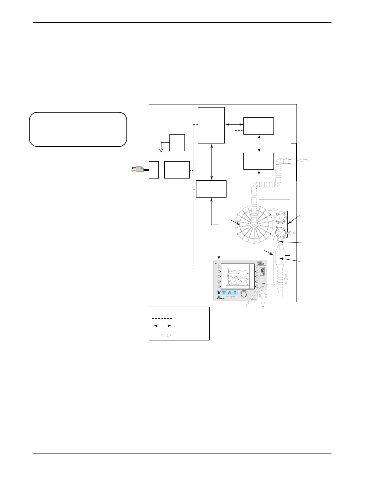
The modular system design employs subsystems, each of which provides a
specific function. Modules are used to expand the capability of a subsystem.
The major subystems and modules are shown in Figure 3-1.
AC
Inlet
Power
Switch
Power Supply
Sub-System
(PSS)
Main Controller
Sub-System
(MCS)
Display/Control
Sub-System
(D/CS)
Keypad and LCD
Blower
IPAP
15
cm H2O
EPAP
6
O
cm H
2
Rate
12
BPM
MODE: S/T MONITORING
P (cm H2O)
Vol (ml)
Flow (L/min)
V
T
1000
ml
MinVent
Pressure Air Flow
Sub-System
To MCS
%O
2
55
PS = 9
cm H2O
Options
PIP
15
cm H2O
14
L/min
(PAS)
Air Flow
Module
(AFM)
%
Air Filter
PVA
PVA
(pressure valve
(pressure valve
assembly
assembly)
Exhaust
Injection
O
2
AFM
(mass airflow
sensor)
Ambient
Air
Point
KEY
Power Distribution
Data Flow
Air Flow
Figure 3-1. BiPAP Vision Electronics and Air Flow Systems.
BiPAP Vision Clinical Manual
Patient Pressure
Tubing
Patient
Circuit
Page 22

3-3
PSS
MCS
PAS
D/CS
AFM
PVA
The Power Supply Subsystem (PSS) provides DC power to the Vision unit
from an AC source.
The Main Controller Subsystem (MCS) performs all control, data acquisition,
and calculations required to deliver the user-selected parameters. In addition,
the MCS performs the startup test and is responsible for reporting all errors.
This subsystem may also be called the Main Control (MC) Board.
The Pressure Air Flow Subsystem (PAS) controls the blower and valves to
regulate gas flow into the patient circuit to maintain the preset pressure at the
patient connection. This subsystem may also be called the Pressure Control
(PC) Board.
The Display/Control Subsystem (D/CS) processes user input from the keyboard
and passes information to the MCS. The D/CS receives relevant display data
for the display screen from the MCS. This subsystem may also be called the
Display Control (DC) board.
The Air Flow Module (AFM), including the mass airflow sensor, provides
measurement of gas flow from the PAS, allowing the PAS to measure total
flow in order to maintain the preset pressure.
The Pressure Valve Assembly (PVA) regulates system flow and pressure. The
In Line Flow Restrictor Valve (ILFR) and the Pressure Regulation Valve
(PRV) make up this assembly.
BiPAP Vision Clinical Manual
Page 23

3-4
3.2.2 OXYGEN MODULE
The Oxygen Module regulates and proportions oxygen into the air from the
blower according to the oxygen concentration level set on the Parameters
screen. At settings of 30 percent oxygen or less the delivered oxygen percentage will be the set percentage ± 3, except that the delivered concentration will
not be below the concentration in air (21 percent). At set concentrations above
30 percent the error range is proportional to the set concentration, and the
possible range of inspired oxygen can be estimated as the set concentration
± 10 percent of the set concentration. The selectable concentration range is
from 21% to 100%.
The graph in Figure 3-2 represents the set oxygen concentration possible for a
given circuit flow. The higher the oxygen concentration settings, the higher the
oxygen flow rates required from the oxygen module and the lower the air flow
rate from the blower.
1.0
0.9
0.8
0.7
0.6
Oxygen Concentration
0.5
0.4
240210190170150130
Total Circuit Flow, L/min
Figure 3-2. Total Flow Available to Maintain
a Set Oxygen Concentration.
An “O2 Flow” alarm is activated if the oxygen inlet supply is lost. See Chapter
13 for further information concerning the alarm.
Refer to Chapter 12 for additional information concerning the use of oxygen
with the BiPAP Vision ventilator.
BiPAP Vision Clinical Manual
Page 24
3-5
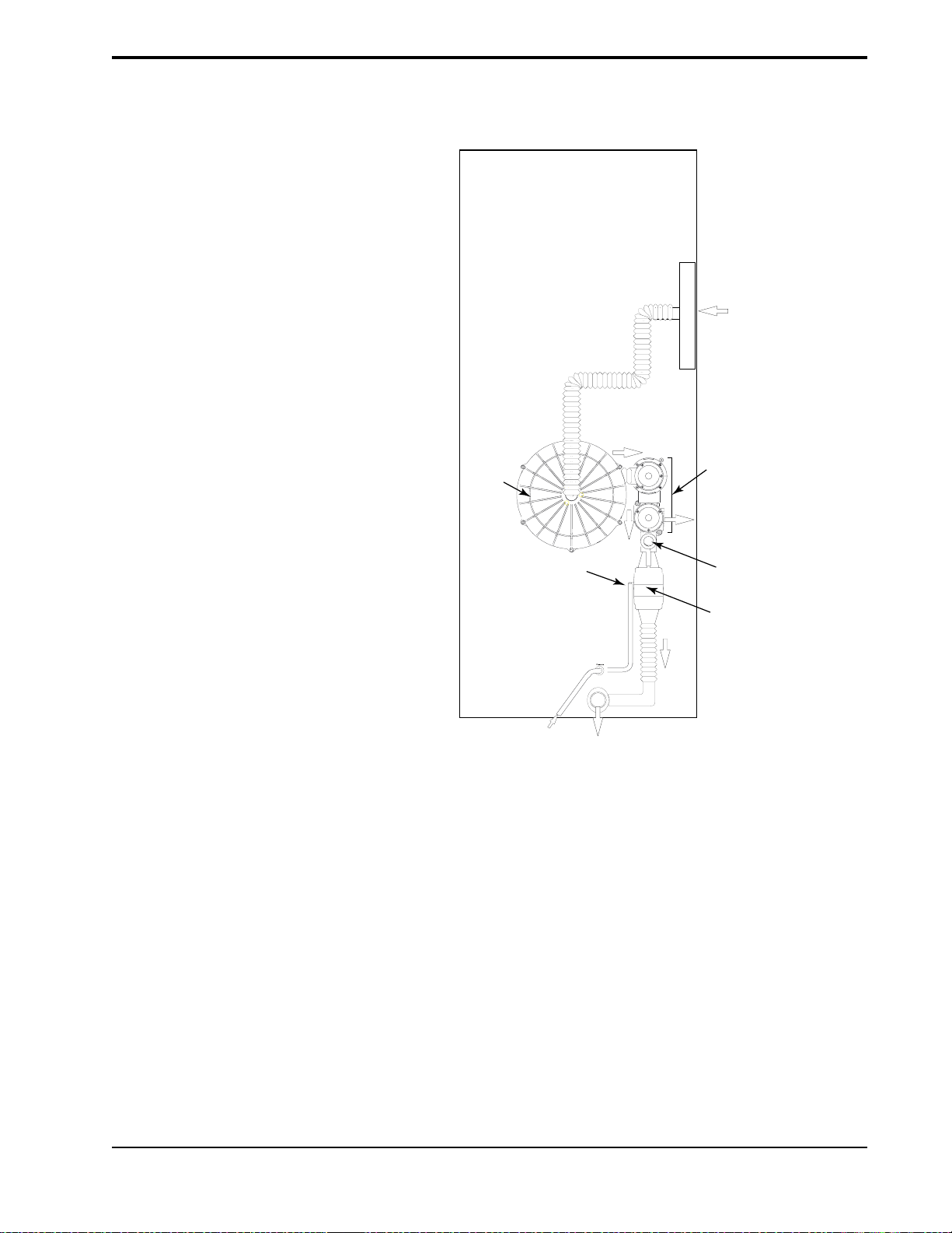
3.2.3 PNEUMATIC SYSTEM
Figure 3-3 provides a representation of the method for generation, control and
delivery of therapy.
Air Filter
Ambient
Air
Blower
PVA
Exhaust
To PAS
Proximal Pressure
Line
To
Patient
O2 Injection
Point
AFM
(mass airflow
sensor)
Figure 3-3. The BiPAP Vision Pneumatic System.
Ambient air is drawn through the air inlet filter and pressurized in the blower
assembly. System flow and pressure are then regulated at the blower outlet by
the Pressure Valve Assembly (PVA). There are two valves in the valve
assembly that work in tandem to produce the desired pressure in the circuit.
During the IPAP phase, flow from the blower is directed through the patient
circuit at the preset pressure. During expiration and transition to the EPAP
phase, the PVA responds as necessary to allow excess flow to be exhausted
from the system to attain EPAP.
A pneumotach located in the Air Flow Module (AFM) is positioned after the
PVA and immediately before the machine outlet. The AFM monitors total gas
flow and machine pressure and transmits the data to the main controller system.
The proximal pressure is measured at the patient connection and compared to
the set pressure. The delivered pressure is thereby controlled and maintained at
the patient connection.
BiPAP Vision Clinical Manual
Page 25

3-6
3.2.4 S
TANDBY MODE
The Standby mode, activated when the Standby key on the Monitoring screen
is pressed, decreases the output flow to an idle state. This feature allows the
clinician to place the ventilator in Standby while performing mask fittings,
setting the prescription, etc. The Standby mode may be selected when no
patient is connected to the Vision ventilator.
When the Standby mode is activated, the graph display area is blanked and
STANDBY flashes in the middle of the screen. All measured parameters are
zeroed.
In the Standby mode, all patient alarms are deactivated. Only the Vent Inop and
CheckVent alarms are active. The following keys remain active:
• PARAMETERS
• MODE
• ALARMS
• Options
If you make any changes to the system (e.g., parameters changes, alarm
settings, etc.), the changes are effective when you exit the Standby mode.
The Standby mode is manually deactivated by pressing the Standby key a
second time. As a safety feature, the Standby mode is automatically deactivated
if the Vision senses that a patient is connected to the circuit and is triggering
spontaneous breaths.
BiPAP Vision Clinical Manual
Page 26
3-7
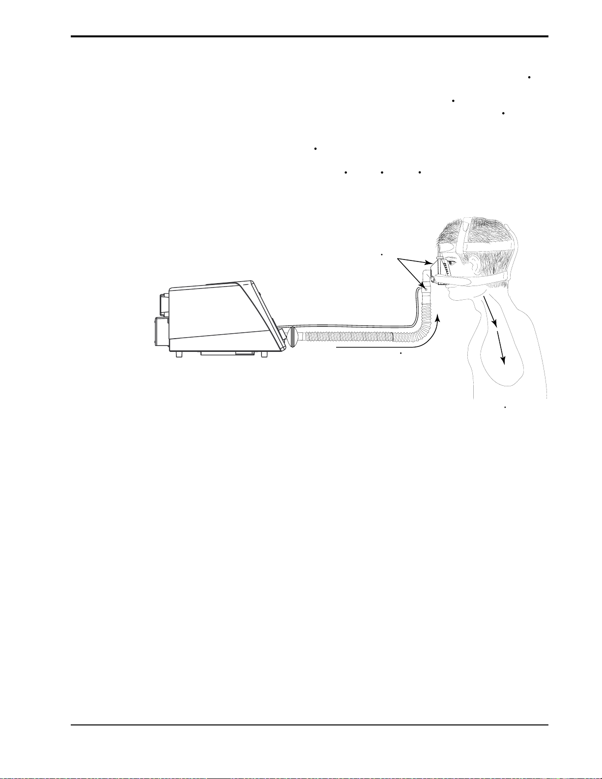
3.2.5 FLOW ANALYSIS
Vision
Unit
The accuracy and responsiveness of the system is maintained by continuous
analysis of the delivered flow. The flow measured at the Air Flow Module
(AFM) is analyzed to derive a signal proportional to the Total Flow Rate (V
in the patient circuit. This signal contains a component derived from the flow
delivered to the patient (Estimated Patient Flow Rate, [V
component derived from circuit leaks (Estimated Leak Flow Rate, [V
]) as well as a
est
leak
]).
Circuit leaks are comprised of intentional leak through the exhalation port as
well as any unintentional leaks that may be present in the circuit or at the
patient connection (V
= intentional + unintentional leaks).
leak
V
= V
tot
(Intentional + Unintentional)
Leak (V
est
leak
+ V
)
leak
)
tot
Total Flow (V
)
tot
Figure 3-4. Data Locations for Flow Analysis.
Patient
Flow
(V
est
)
BiPAP Vision Clinical Manual
Page 27
3-8
3.3 BiPAP® Auto-T rak
Sensitivity
3.3.1 LEAK TOLERANCE
™
An important characteristic of the BiPAP Vision ventilator is its ability to
recognize and compensate for unintentional leaks in the system and to automatically adjust its trigger and cycle algorithms to maintain optimum performance in the presence of leaks. This feature is known as Auto-Trak Sensitivity. The following sections examine this function in detail by describing the
leak tolerance function and sensitivity.
Leak tolerance is the unit’s ability to respond to changes in leaks. The BiPAP
Vision ventilator uses two primary mechanisms to identify and adjust to leaks.
1. Expiratory Flow Rate Adjustment
At end expiration the total flow in the patient circuit should equal the baseline
leak (V
) which consists of intentional (exhalation port) and unintentional
leak
(mask, mouth) leaks. Once the unit has been in EPAP for 5 seconds, the total
flow is compared to the originally established value of V
. At this point, the
leak
Vision flow sensing circuit makes the assumption that the patient’s flow is zero,
so that the total circuit flow, V
Thus, under this condition of assumed zero patient flow, if V
V
, the BiPAP Vision will adjust its calculation of the baseline leak. Figure
leak
3-5 shows graphically how V
, should be equal to V
tot
is adjusted in the case of an increase in leak.
leak
leak
.
is not equal to
tot
ORIGINAL
BASELINE
(V
)
leak
Spontaneous Trigger
INSPIRATION
ADDITIONAL
LEAK
TOTAL FLOW
(V
)
tot
CYCLE TO EPAP
END EXPIRATION
5.0 SECONDS
Figure 3-5. Expiratory Flow Rate Adjustment.
NEW BASELINE
Adjustment of
(V
)
leak
BiPAP Vision Clinical Manual
Page 28
2. Tidal Volume Adjustment
Inspiratory (VTI) and expiratory (VTE) tidal volumes are determined by the
estimated patient flow, and compared on a breath-by-breath basis. If the
measured volumes during inspiration differ from expiration, the difference in
volume is assumed to be due to an unintentional circuit leak. The baseline
(V
) is adjusted in the appropriate direction to reduce the difference in
leak
VTI - VTE on the next breath. This prevents abrupt changes in sensitivity based
on random changes in the breathing pattern, and allows the baseline (V
leak
) to
accommodate to the new breathing pattern.
Tidal volume adjustment can be observed on the tidal volume waveform graph
as illustrated in Figure 3-6.
Additional
Leak
Introduced
New
Baseline
3-9
3.3.2 SENSITIVITY
V
est
V
0
Volume
Adjustment
0
T
Figure 3-6. Tidal Volume Adjustment.
An essential feature of the BiPAP Vision ventilator while operating in the S/T
Mode is its ability to effectively sense spontaneous breathing efforts, which
causes the ventilator to trigger to IPAP and cycle to EPAP. Because no preset
sensitivity threshold can assure patient and machine synchrony with changing
breathing efforts and circuit leaks, the BiPAP Vision ventilator continuously
tracks patient breathing patterns and automatically adjusts sensitivity thresholds
to ensure optimum sensitivity as breathing patterns change or as circuit leaks
change. The algorithms used to ensure optimum sensitivity are the Volume
Trigger, Shape Signal, and the Spontaneous Expiratory Threshold (SET).
BiPAP Vision Clinical Manual
Page 29

3-10
Volume Trigger
(EPAP to IPAP)
Shape Signal
(EPAP to IPAP)
(IPAP to EPAP )
The volume trigger is one method used to trigger IPAP during spontaneous
breathing in the S/T Mode. The volume trigger threshold is 6 cc of accumulated volume above the baseline leak (V
inspiratory flow causing 6 cc of volume to accumulate above baseline (V
). When patient effort generates
leak
leak
),
IPAP is triggered:
Volume trigger threshold = 6 cc volume above V
baseline
leak
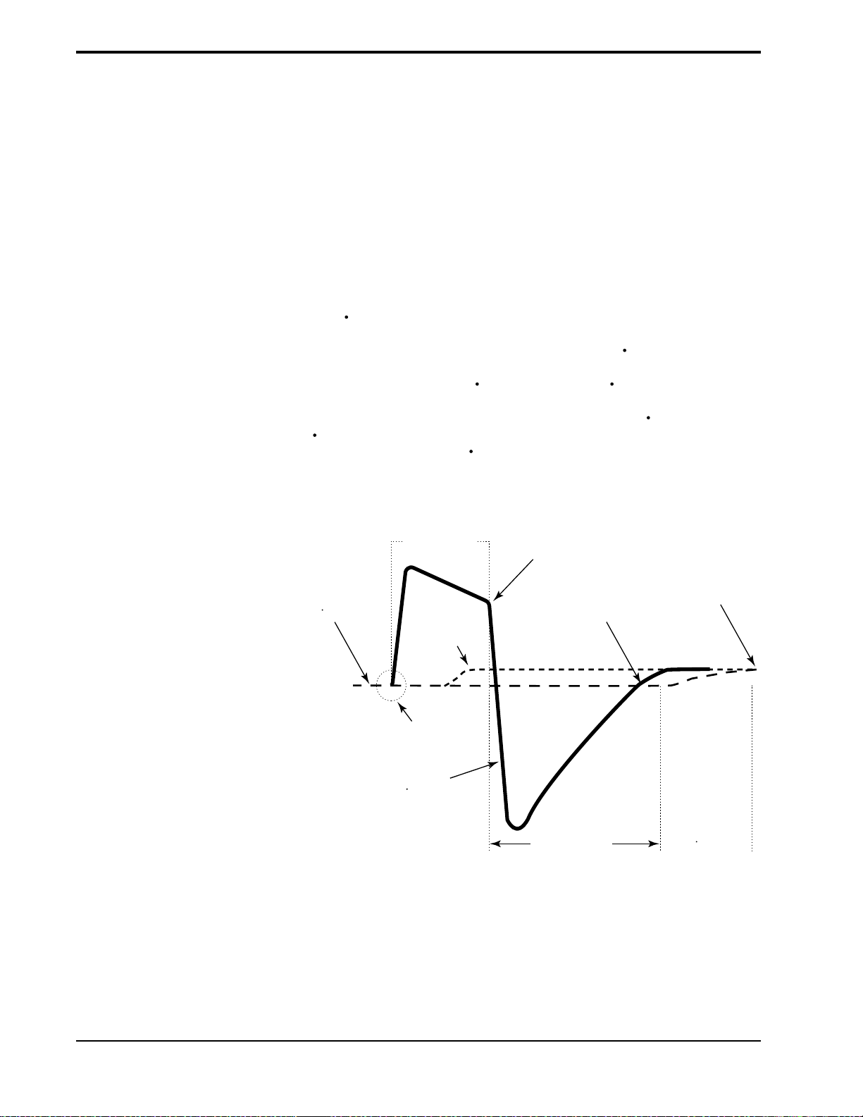
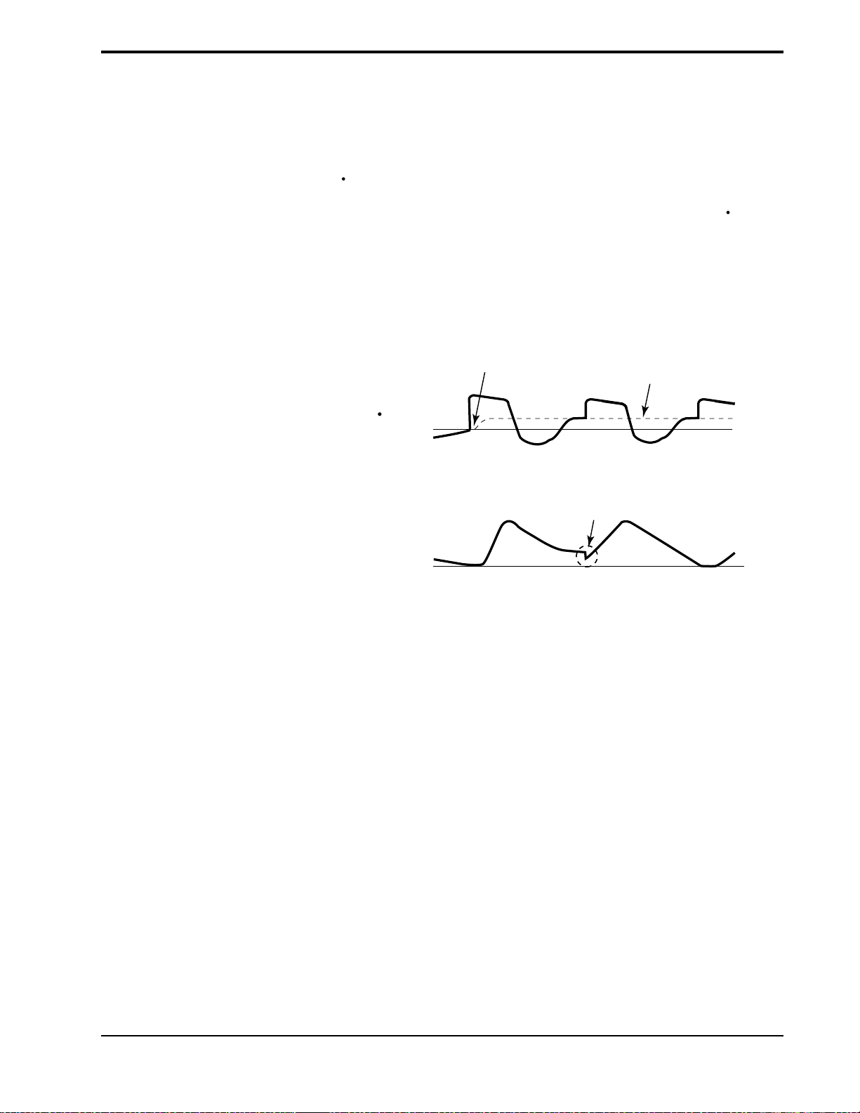
The shape signal is another method used to trigger IPAP and/or cycle off IPAP
to EPAP during spontaneous breathing in the S/T Mode. This signal continuously tracks patient inspiratory and expiratory flow and adjusts the spontaneous
trigger and cycle thresholds for optimum sensitivity. The Shape Signal appears
as a shadow image of the patient’s actual flow. The shape signal functions as a
sensitivity threshold at either inspiration or expiration. When the patient’s flow
rate crosses the shape signal the unit changes pressure levels. Figure 3-7
illustrates how the shape signal is superimposed onto the actual waveform to
trigger and cycle off IPAP.
The shape signal is created by offsetting the signal from the actual patient flow
by 15 L/min and delaying it for a 300 msec period. This intentional delay
causes the shape signal to be slightly behind the patient’s flow rate. A sudden
change in patient flow will cross the shape signal, causing the pressure level to
change.
PRESSURE
FLOW
IPAP
EPAP
Shape
Signal
Estimated
Patient
Flow
Cycle to
EPAP
Crossover
Point
Trigger to
IPAP
Crossover
Point
Figure 3-7. Shape Signal.
Tracking the patient’s flow pattern with the Shape Signal provides a sensitive
mechanism to trigger to IPAP or cycle to EPAP in response to changing
breathing patterns and circuit leaks.
BiPAP Vision Clinical Manual
Page 30
3-11
Spontaneous Expiratory
Threshold
(IPAP to EPAP)
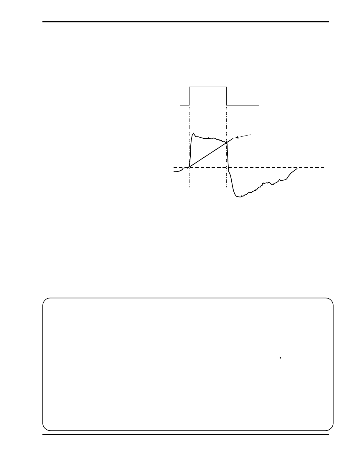
A second method used to cycle off IPAP during spontaneous breathing in the
S/T Mode is called Spontaneous Expiratory Threshold (SET). The SET is an
electronic signal that rises in proportion to the inspiratory flow rate on each
breath. When the Spontaneous Expiratory Threshold (SET) and actual patient
flow value are equal, the unit cycles to EPAP.
IPAP
PRESSURE
EPAP
Spontaneous
Expiratory
Threshold
FLOW
Maximum IPAP Time
(IPAP to EPAP)
Flow Reversal
(IPAP to EPAP)
Summary
Figure 3-8. Spontaneous Expiratory Threshold.
A maximum IPAP time of 3.0 seconds acts as a safety mechanism to limit the
time spent at the IPAP level during spontaneous breathing in the S/T Mode.
Once the time limit is reached, the unit automatically cycles off IPAP to the
EPAP level.
As flow begins to decrease during IPAP, a flow reversal can occur due to a
large leak around the mask or because the patient’s mouth is open. When the
Vision unit senses this flow reversal, the unit automatically cycles to the EPAP
level.
The sensitivity criteria for spontaneous breathing in the S/T mode can be
summarized as follows:
Spontaneous Trigger to IPAP
A transition from EPAP to IPAP will occur when one of the following conditions is met:
• Patient flow exceeds the shape signal
• 6 cc inspired volume accumulates above baseline flow (V
leak
)
Cycle to EPAP
The transition from IPAP to EPAP will occur when one of the following
conditions is met:
• Patient flow is less than the shape signal
• Spontaneous Expiratory Threshold (SET) is achieved
• A 3.0 second maximum IPAP time has occurred (safety feature)
• Flow reversal occurs during IPAP (safety feature)
BiPAP Vision Clinical Manual
Page 31

3-12
3.4 Description of
System Alarms
3.4.1 CHECK VENTILATOR
Check Vent
3.4.2 VENTILATOR
INOPERATIVE
Vent Inop
The ventilator incorporates self-diagnostic testing capabilities and a number of
safety features. System internal functions are checked automatically at start- up
and periodically throughout operation. The microprocessors continuously
obtain readings from internal sensors to monitor machine functions and
operating conditions. Device malfunctions or abnormal operating conditions
are analyzed and reported according to the level of severity. Two primary
alarm functions, Check Ventilator and Ventilator Inoperative, are available to
identify a system malfunction.
The Check Ventilator alarm alerts the clinician of a potential abnormal operating condition by illuminating the yellow “eye” icon on the display panel and
activating an audible alarm. The audible alarm can be silenced with the Alarm
Silence Key; the audible alarm will not reactivate after two minutes (as it
usually does). The visual indicator cannot be reset and remains illuminated
until the error is corrected. The ventilator continues to operate during a “Check
Vent” condition but should be referred for service as soon as possible.
The Ventilator Inoperative Alarm indicates a machine malfunction by illuminating the red “wrench” icon on the display panel and activating an audible
alarm. The ventilator immediately powers down and opens the internal valves,
allowing ambient air to be drawn in through the ventilator. The audible and
visual alerts remain active and cannot be silenced until the power is turned off.
NOTE: Additional adjustable and
system alarms are discussed in
Chapter 13—Alarms.
3.4.3 EXHALATION PORT
ALARM
WARNING: Always inspect the
exhalation port and circuit for partial
obstructions before manually activating the Learn Base Flow. Otherwise,
the Vision may establish the obstructed baseline flow as “normal,”
which could cause the Low Leak
alarm to ignore occlusions in the
circuit or exhalation port.
The alarm is intended to identify an occlusion or low leak at the exhalation
port. The alarm is preset to activate at < 5 L/min or 50 % of the baseline flow,
whichever is greater, for a period of one minute. During the EPAP phase, the
minimal baseline flow in the circuit is a result of the intentional leak at the
exhalation port. If the exhalation port becomes occluded, the baseline flow will
decrease below the alarm threshold and the alarm will be activated. The alarm
message for a low leak condition is “Exh. Port.”
The leak rate of the exhalation port is determined during the Exhalation Port
Test and is used to determine the baseline flow. If the test is not performed, a
default value is used. The baseline flow is automatically recalculated during a
mode change.
Some circuit changes (e.g., oxygen or supplemental flow added to the circuit
during operation) can shift the baseline flow and inadvertently activate the
alarm. Under these circumstances, the clinician should reestablish the baseline
flow for the circuit condition by manually selecting a new learn period. This is
done by selecting the Learn Base Flow soft key in the Modify Alarms screen.
The unit will learn a new baseline flow for the alarm based on the existing
circuit conditions. The learn period is two minutes during which the Learn
Base Flow soft key is highlighted.
BiPAP Vision Clinical Manual
Page 32

3-13
3.5 User Interface
Main Power
Operational
Hard Keys
Indicator
The primary user interface is the front panel of the Vision ventilator. A Liquid
Crystal Display (LCD) screen provides real time graphics for pressure, volume,
and flow; control features; calculated patient and machine parameters; and
alarm conditions. The front panel also contains the user input controls,
consisting of a set of hard and soft keys and a rotary adjustment knob.
PIP
15
cm H2O
cm H2O
Soft Key
Descriptors
%O
2
set
55
Standby
Options
Soft
Keys
%
Soft
Keys
Soft Key
Descriptors
IPAP
15
cm H2O
EPAP
6
O
cm H
2
Rate
12
BPM
Graphic
Display
MODE: S/T MONITORING
P (cm H2O)
Vol (ml)
Flow (L/min)
V
T
1000
ml
MinVent
14
PS = 9
L/min
Alarm
Hard
Keys
Ventilator
Inoperative
Indicator
Check Ventilator
Indicator
Pressure Line
Port
Patient
Interface
Port
Graph Control
Hard Keys
Adjustment
Knob
Figure 3-9. The BiPAP Vision Ventilator Front Panel.
See Chapter 4 for a complete description of the user interface.
BiPAP Vision Clinical Manual
Page 33

3-14
3.6 Exhalation Port Test
WARNING: Failure to perform the Exhalation Port Test prior to initializing therapy may result in inaccurate estimated
tidal volume and minute ventilation readings. Subsequently, inaccurate minute ventilation readings
could alter the accuracy of the low minute ventilation alarm when set below 3 L/min.
NOTE: Perform the Exhalation Port Test at system power up and when exhalation ports are changed. See Section 6.2,
Starting the Vision System.
NOTE: The Exhalation Port Test must be performed when using the Plateau Exhalation Valve (PEV), because the leak
rate of the PEV is significantly different than the Disposable Exhalation Port or the Whisper Swivel.
When the Start/Stop switch is turned to START and the system completes a
self test, the system Start-up screen is displayed. The Start-up screen allows
the user to perform the Exhalation Port Test. The Exhalation Port Test characterizes the patient circuit by analyzing the leak rate of the exhalation port.
During the test, the system learns the intentional exhalation port leak over the
complete pressure range. The learned leak value is then stored in system
memory and is used to perform leak calculations and provide an accurate
display of patient leak and tidal volume in the Data Display Area. When a test
is performed successfully, the Data Display shows the unintentional leak (the
display will appear as “Pt. Leak” in the Data Display Area). If the test is not
performed or cannot be completed successfully, the system is unable to
accurately know the intentional leak and will display the total leak value
(intentional + unintentional). The display will appear as “Tot. Leak” in the
Data Display Area.
BiPAP Vision Clinical Manual
Page 34

Chapter 4: Controls and Displays
This chapter describes the front panel controls, displays, and interface connections, the rear panel connections and controls, and the available Vision options.
4-1
Main Power
Operational
Hard Keys
Indicator
Soft
Keys
Soft Key
Descriptors
IPAP
15
cm H2O
EPAP
6
cm H
O
2
Rate
12
BPM
Graphic
Display
MODE: S/T MONITORING
P (cm H2O)
Vol (ml)
Flow (L/min)
V
T
1000
ml
MinVent
14
Graph Control
Hard Keys
L/min
PS = 9
PIP
15
cm H2O
cm H2O
Soft Key
Descriptors
%O
2
set
55
Standby
Options
Adjustment
Knob
Soft
Keys
Alarm
%
Hard
Keys
Ventilator
Inoperative
Indicator
Check Ventilator
Indicator
Proximal Pressure
Line Port
Patient
Interface
Port
4.1 Overview
Figure 4-1
Figure 4-1 illustrates the Vision front panel. The front panel includes:
• a set of control keys
• a rotary adjustment knob
• a graphic display panel
• a patient interface port
• a pressure line port
The Vision unit has eight hard keys and ten soft keys to control the ventilator,
graphics, and alarms.
A hard key performs a single function regardless of the screen or display. The
hard keys are:
• MONITORING
• PARAMETERS
• MODE
• ALARMS
• SCALE
• FREEZE/UNFREEZE
• ALARM SILENCE
• ALARM RESET
The function of a soft key changes with the displayed screen. The soft key
function is displayed in its adjacent soft key descriptor.
BiPAP Vision Clinical Manual
Page 35

4-2
4.2 Patient Circuit Connections
Patient Interface Port
The Patient Interface Port accepts a 22 mm ID bacteria filter.
Pressure Line Port
The Pressure Line Port accepts the 1/8" ID Proximal Pressure Line from the
patient circuit to monitor patient pressure.
4.3 Adjustment Knob
The adjustment knob is a rotary knob that changes the value of a parameter that
is selected with a soft key. It is active only when a soft key selection has been
made.
To increase the value of a selected parameter, turn the knob clockwise; to
decrease the value of a selected parameter, turn the knob counterclockwise.
The knob has detents, each of which corresponds to one increment of the
parameter value. The increment is equal to the resolution of the parameter.
For example, when the IPAP parameter is selected, each detent will change the
value of the parameter by 1 cm H2O.
BiPAP Vision Clinical Manual
Page 36

4.4 Soft Keys
4-3
4.4.1 SOFT KEY OPERATION
NOTE: If there is no user activity for
three minutes, the display
returns to the Monitoring
screen.
4.4.2 SOFT KEY
DESCRIPTORS
Parameter
Set Value
Measured
Value
Parameter
Units
EPAP
set
15
15
cm H2O
The BiPAP Vision ventilator has 10 soft keys aligned vertically along the sides
of the LCD screen (5 keys on each side). The functions of the soft keys vary
with the screen displayed. Soft keys are used to select parameters for adjustment, to display screens, or to provide information. When a soft key is pressed,
the adjacent descriptor is highlighted in reverse video indicating the parameter
located in the descriptor box is active and can be modified by using the adjustment knob. A second press of the same soft key deselects the descriptor box.
If a descriptor area is blank, the soft key adjacent to it is inactive. The soft key
controls are described in each pertinent section.
When a soft key is active, the adjacent descriptor is highlighted and displays
data pertinent to the soft key.
When modifying or setting parameters, the descriptor displays the set value and
the parameter units. The CPAP, IPAP, EPAP, and Rate descriptors also display
the measured value in a smaller size below the set value when the parameter is
selected.
BiPAP Vision Clinical Manual
Page 37

4-4
4.5 Hard Keys—Operational
In addition to the soft keys, the Vision ventilator user interface consists of four
main screens, each displayed by one of the four Operational Hard Keys.
BPM
Flow (L/min)
VT 1000 ml MinVent 4 L/min
Operational
Hard Keys
4.5.1 MONITORING HARD KEY
MONITORING
IPAP
MODE: S/T MONITORING
15
cm H2O
P (cm H2O)
EPAP
6
cm H
O
2
Vol (ml)
Rate
12
BPM
Flow (L/min)
V
T
1000
PS = 9
ml
MinVent
14
L/min
%O
2
set
55
%
cm H2O
Options
PIP
15
cm H2O
The hard keys are:
• MONITORING
• PARAMETERS
• MODE
• ALARMS
Purpose: Display the Monitoring screen for the active mode. Allows the
operator to return to the Monitoring screen from any screen. No
parameter, alarm, or mode changes can be made while the
Monitoring screen is displayed.
Active: At all times
Note: If there is no user activity (e.g., pressing any keys) for three
minutes while displaying any other screen, the system automatically returns to the Monitoring screen.
The Monitoring screen can be considered the “home”
screen of the display. It displays the current operating
mode, contains graphic displays of pressure, tidal volume,
and flow, and includes numerical data displays for calculated and measured parameters. When using the optional
oxygen module, the screen also displays the set oxygen
concentration.
BiPAP Vision Clinical Manual
Page 38

4.5.2 PARAMETERS HARD KEY
4-5
P ARAMETERS
IPAP
MODE: S/T MODIFY
set
15
PARAMETERS
15
cm H2O
EPAP
set
6
6
cm H2O
Rate
set
12
12
Timed Insp
set
3.0
P (cm H2O)
Vol (ml)
BPM
Flow (L/min)
sec
V
T
700
ml
Ti/Ttot
15
%
MinVent
Pt. Leak
14
1
L/min
L/min
PS = 9 cm H
PIP
8
Pt. Trig
cm H2O
4.5.3 MODE HARD KEY
MODE
Purpose: Display the Modify Parameters screen for the active mode. The
Modify Parameters screen allows the operator to change a
parameter for the active mode.
Active: At all times
%O
2
O
set
55
IPAP
Rise Time
set
0.1
2
%
sec
The Modify Parameters screen allow the operator to review
and adjust the parameters for the current operational mode.
It displays the current operating mode, contains graphic
displays of pressures, tidal volume, and flow, and includes
numerical displays for calculated and measured parameters.
5
%
Purpose: Display the Change Mode screen. Real time graphic and numeric
displays for the current mode provide for continuous monitoring
of the patient and ventilator while making changes.
Active: At all times
CHANGE MODE
P (cm H2O)
Vol (ml)
Flow (L/min)
OPERATING IN: S/T
4.5.4 ALARMS HARD KEY
ALARMS
Hi P
MODE: S/T MODIFY
ALARMS
30
set
P (cm H2O)
cm H2O
Lo P
set
13
cm H2O
Vol (ml)
Lo P Delay
set
16
sec
Flow (L/min)
Apnea
set
Disabled
sec
Learn
Base
Flow
V
T
Ti/Ttot
700
ml
MinVent
15
14
%
Pt. Leak
1
PIP
8
cm H2O
L/min
Pt. Trig
5
L/min
%
CPAP
Lo MinVent
set
20
Hi Rate
set
80
Lo Rate
set
5
Help
The Change Mode screen allows the operator to review
and select a new operating mode. Selecting a new mode
from the Change Mode screen will initiate the change
mode sequence and permit the user to adjust the parameters
for the new mode before activating the mode.
Purpose: Display the Modify Alarms screen.
Active: At all times
The Modify Alarms screen allows the operator to review
and change the alarm limits for the active mode. While
L/min
BPM
BPM
viewing the Modify Alarms screen, real-time graphic and
calculated numeric displays for the active mode provide for
continuous monitoring of the patient and ventilator.
BiPAP Vision Clinical Manual
Page 39

4-6
4.6 Hard Keys—Graph Control
Graph Control
Hard Keys
The Graph Control Hard Keys are:
• SCALE
• FREEZE/UNFREEZE
4.6.1 SCALE HARD KEY
4.6.2 FREEZE/UNFREEZE
HARD KEY
Purpose: Display the Modify Scale screen. The Modify Scale screen
allows the operator to change the graph scales.
Active: At all times, except in the Change Mode screen.
Purpose: Freeze the graph displays if the displays are scrolling when the
key is pressed. Conversely, it unfreezes the display if the displays
are frozen when the key is pressed.
Active: At all times except in the Change Mode screen.
Note: Real-time pressure, flow, and volume data are not plotted when
the graphs are frozen. When the Freeze Key is active the message
“Freeze Active” is displayed in the Mode/Message Area.
BiPAP Vision Clinical Manual
Page 40

4.7 Hard Keys—Alarm
9
s
set
55
cm H2O
The Alarm Hard Keys are:
• SILENCE
• RESET
%
Standby
Options
4-7
Alarm
Hard Key
4.7.1 ALARM SILENCE HARD
KEY
Purpose: Turns off the audible alarm for two minutes. Any further pressing
of the Alarm Silence Hard Key has no effect on the alarm. When
the alarm silence is active, the message “Alarm Silenced” appears
in the Mode/Message Area for the duration of the silence period.
Any new alarm conditions that occur during the silence period
will provide a visual alert, but will not trigger the audible alarm.
Active: At all times
NOTE: The Ventilator Inoperative Alarm and the Apnea Alarm will override Alarm Silence.
4.7.2 ALARM RESET HARD
KEY
Purpose: Cancels the alarm silence period, resets the visual alarms, returns
the Mode/Message and Graphic Display Areas to their normal
formats, and resets the alarm detection logic. The alarm reactivates if the condition causing the alarm has not been corrected.
Active: At all times
CAUTION: To ensure the timely detection of any new alarm condition, never leave a patient unattended while the
alarm is silenced.
BiPAP Vision Clinical Manual
Page 41

4-8
4.8 V entilator W arning Indicators
4.8.1 VENTILATOR
INOPERATIVE INDICATOR
Vent Inop
4.8.2 CHECK VENTILATOR
INDICATOR
Purpose: Alerts of a machine malfunction by illuminating the red “wrench”
icon on the display panel and activating an audible alarm. The
ventilator immediately powers down and opens the internal valves
allowing ambient air to be drawn through the ventilator by
spontaneous breathing.
The audible and visual alerts remain active and cannot be silenced
until the Start/Stop switch is placed in the Stop position.
Check Vent
Purpose: Alerts of a potential abnormal operating condition by illuminating
the yellow “eye” icon on the display panel and activating an
audible alarm. The audible alarm can be temporarily silenced
with the Alarm Silence Key. However, the visual indicator
cannot be reset and remains illuminated until the error is corrected. The unit should be referred for service.
BiPAP Vision Clinical Manual
Page 42

4.9 Graphic Display
As shown in Figure 4-2, the Graphic Display consists of three areas: the Mode/
Message Area, the Graphic Display Area, and the Data Display Area.
Mode/Message
Area
Graphic Display
Area
4-9
IPAP
EPAP
Rate
15
cm H2O
6
cm H
12
BPM
MODE: S/T MONITORING
P (cm H2O)
O
2
Vol (ml)
Flow (L/min)
V
T
1000
ml
Data
Display
Figure 4-2. Graphic Display Areas.
MinVent
14
L/min
PS = 9
PIP
15
cm H2O
cm H2O
%O
2
set
55
Standby
Options
%
4.9.1 MODE/MESSAGE AREA
4.9.2 GRAPHIC DISPLAY AREA
4.9.3 DATA DISPLAY AREA
During normal operation, the Mode/Message Area displays the active mode and
the screen type. In alarm conditions, the Mode/Message Area displays the
alarm messages.
The Graphic Display Area displays the real-time graphs for pressure, volume,
and patient flow. A Timed Breath Indicator (V) appears on the Volume graph
in the S/T mode to mark the start of a time-triggered machine breath.
The Data Display Area can show up to six nonadjustable ventilation parameters, depending on the active mode. The display includes:
• Estimated Tidal Volume
• Estimated Minute Ventilation
• Peak Inspiratory Pressure
• Inspiratory Time/Total Cycle
Time
• Patient or Total Leak
• % Patient Triggered Breaths
BiPAP Vision Clinical Manual
Page 43

4-10
4.9.4 DATA VALUES
Monitoring Screen (see Figure 4-3)
The Monitoring screen provides measured values for:
• CPAP (When operating in the CPAP Mode, the CPAP value is
displayed instead of the IPAP and EPAP values.)
• IPAP
• EPAP
• Peak Inspiratory Pressure (PIP)
Three calculated values are displayed in the Data Display Area:
• Estimated Exhaled Tidal Volume (VT)
• Estimated Exhaled Minute Ventilation (MinVent)
• Rate (total respiratory rate)
CPAP
or
IPAP
EPAP
Rate
IPAP
cm H2O
EPAP
cm H
Rate
MODE: S/T MONITORING
15
P (cm H2O)
6
O
2
Vol (ml)
12
BPM
Flow (L/min)
PS = 9
cm H2O
Standby
cm H2O
Peak Inspiratory
Options
Pressure
Estimated Exhaled
Tidal Volume
V
T
1000
ml
MinVent
14
L/min
Estimated
Minute Ventilation
PIP
15
Figure 4-3. Data Values Displayed in the Monitoring Screen.
CPAP, IPAP, and EPAP (cm H2O) - The CPAP, IPAP, and EPAP displays
are measurements taken at the patient connection. Displays are real-time
measurements for each breath.
Rate (BPM) - The total breathing rate is a running average from the six
previous breaths (spontaneous + machine). All display values are updated at
the end of each breath.
Estimated Exhaled Tidal Volume (ml) - Displays an estimated exhaled tidal
volume reading for the previous breath. The display is updated at the end of
each breath. The estimated exhaled tidal volume is obtained by integration of
patient flow, uncorrected to BTPS. If large variations in flow (>15 L/min)
occur between breaths, the tidal volume display value will flash, signaling an
unstable reading. When the volumes are stabilized the display value remains
constant.
BiPAP Vision Clinical Manual
Page 44

Estimated Exhaled Minute Ventilation (L/min) - Displays the estimated
Vol
(ml)
P
(cm H2O)
Flow
(L/min)
MODE: S/T MODIFY
PARAMETERS
IPAP
cm H2O
%O
2
IPAP
Rise Time
%
15
15
set
EPAP
cm H2O
6
6
set
Rate
PS = 9 cm H
2
O
BPM
12
12
set
0.2
set
Timed Insp
sec
sec
3.0
set
55
set
V
T
700
ml
PIP
8
cm H2O
MinVent
14
L/min
Ti/Ttot
15
%
Pt. Leak
10
L/min
Pt. Trig
5
%
Inspiratory Time/
Total Cycle Time
Patient Leak
Percentage of
Patient-Triggered
Breaths
exhaled minute ventilation based on a running average of the previous six
breaths. The display is updated at the end of each breath.
Peak Inspiratory Pressure (cm H2O) - Displays the peak pressure level
obtained during the breath. The measurement is proximal to the patient
connection. The display is updated at the end of each inspiration.
Parameters Screen (see Figure 4-4)
4-11
Figure 4-4. Data Values Displayed in the Parameters Screen.
Additional calculated values are displayed in the Data Display Area when the
Parameters screen is active for the CPAP or S/T Mode.
Leak (L/min) - Displays either the Patient Leak or Total Leak.
Patient Leak - When the exhalation port test is successfully
performed, the ventilator learns the intentional leak rate at the
exhalation port and subtracts this value from the total leak.
Therefore, the remaining leaks are a result of unintentional
leaks typically found at the patient connection. The patient
leak is the average leak value calculated over the entire
breathing cycle. The display value is updated after each
breath.
Total Leak - If the exhalation port test is not performed, the
total (intentional + unintentional) leak is displayed. Total leak
is the average leak value calculated during the entire breathing
cycle. The display value is updated after each breath.
BiPAP Vision Clinical Manual
Page 45

4-12
Ti/Ttot (%) - Inspiratory Time/Total Cycle Time- Displays
the ratio of inspiratory time (Ti) to the duration of the total
respiratory cycle (Ttot). Display is updated at the end of each
breath.
% Pt. Triggered (%) - Percentage of Pateint-Triggered
Breaths - Displays the ratio of breaths triggered by the patient
to total breaths. This value is obtained by dividing the number
of patient-triggered breaths over the previous 30 minute period
by the total number of breaths (machine + patient) over the
same period. The display is updated every minute and is reset
by a mode change or power-off condition. Active in the S/T
mode only.
BiPAP Vision Clinical Manual
Page 46
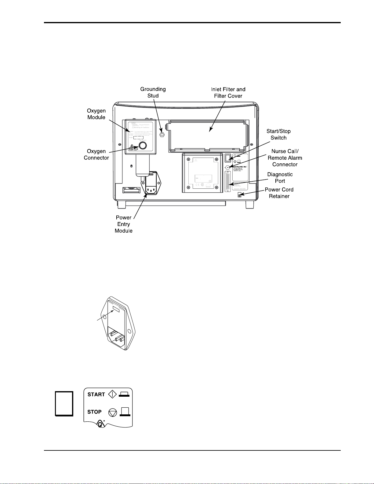
4-13
4.10Rear Panel
Figure 4-5 shows the rear panel of the Vision unit. The rear panel includes:
• Power entry module
• Inlet filter and cover (see section 15.3)
• Oxygen Module (see chapter 14)
• Start/Stop switch
• Power cord retainer
Oxygen Inlet Pressure Range:
50 to 100 psig
580123
Warnings & Cautions
WARNING:
Disconnect power supply before servicing.
WARNING:
For continued protection against risk of fire, replace
with same type and rating of fuse.
WARNING:
Equipment not suitable for use in the presence of
flammable anaesthetic mixture.
WARNING:
Proper grounding is essential for safety.
CAUTION:
Federal law restricts this device to sale by or on the
order of a physician.
CAUTION:
Do not immerse the device.
100 - 240 V , 50/60 Hz
3.0 A Max.
100 - 240 V - T6.3 A, 250 V, 5 x 20 mm
CLASS I
TYPE BF
580NEW
V
¤
DE
0123
NRTL/C
4.10.1 POWER ENTRY MODULE
115V
Voltage Setting
is Visible in Window
4.10.2 START/STOP SWITCH
Figure 4-5. BiPAP Vision Rear Panel.
The AC Inlet accepts a standard hospital-grade grounded power cord.
The module contains two fuses, placed in individual fuse drawers. The factoryset inlet voltage is set to the proper voltage for the country of operation.
Chapter 14 describes how the fuses are inserted. See Chapter 16 for the proper
fuse size and rating.
The Start/Stop switch is a push-button type switch, with “START” at the in
position. The Start switch begins operation, but power is always applied to the
Vision unit when the power cord is plugged into an operational wall outlet.
BiPAP Vision Clinical Manual
Page 47

4-14
4.10.3 OXYGEN MODULE
!
Warnings & Cautions
Recommended Oxygen Pressure Range:
WARNING: Do not exceed maximum working
WARNING: Disconnect supply before servicing.
35 to 100 psig
CAUTION: Do not operate with cover removed.
pressure.
CAUTION: When servicing, use only approved
replacement parts.
¤
Oxygen
Connector
The Oxygen Module provides a means of controlling the oxygen concentration
delivered to the patient. The module can control the oxygen concentration
from 21 to 100%.
Serial #
4.10.4 DIAGNOSTIC
CONNECTOR
4.10.5 NURSE CALL/
R
EMOTE ALARM
CONNECTOR
4.10.6 GROUNDING STUD
4.1 1 Internal Alarm
Battery
The Diagnostic connector is for use by Respironics-authorized service
personnel only.
The Nurse Call/Remote Alarm connector is a BNC-type connector that can be
used to connect to most hospital call and alarm systems. It can also be used to
connect to the Respironics Remote Alarm unit (Respironics part number
34003). Refer to Chapter 13 for a discussion of the Nurse Call/Remote Alarm
operation.
The grounding stud is provided as a chassis ground connection for testing
purposes.
The Vision unit contains an internal NiCAD battery to sound the audible alarm
and illuminate the Vent Inop indicator for greater than 2 minutes if AC power is
lost. The battery does not support the operation of the Vision unit.
NOTE: When the Vision is started for the first time, the internal alarm battery may be discharged, causing the Check
Vent visual and audible indicators to activate. If this happens, start the unit and operate in the
Standby mode for a minimum of 2 hours to recharge the battery enough to eliminate the low battery alarm. See
section 14.7 for complete battery maintenance information.
After the battery is charged, you must access the Options screen and clear the error codes. See Section 10.2.1.
4.12Parameter
Retention
The Vision unit uses a lithium battery to store information on the mode,
parameters, and alarm limits in use. The information is retained in memory for
at least seven years with no AC power applied..
BiPAP Vision Clinical Manual
Page 48

4-15
4.13 Options
To display which, if any, of the options are installed on your machine, press the
OPTIONS Soft Key on the Monitoring screen, then press the System Info Soft
Key on the Options screen. The Mode/Message Area displays the software
version and which modules are installed. Chapter 10 details the operation and
display of the Options screen.
BiPAP Vision Clinical Manual
Page 49

4-16
BiPAP Vision Clinical Manual
Page 50

Chapter 5: Operational Flow Charts
This chapter presents the four primary Vision ventilator operations as flow diagrams. The operations are Start-up,
Change Mode, Change Parameters, and Modify Alarms. The instructions are abbreviated to show only the major steps.
To review an operation in detail, refer to Chapters 6 through 11.
5.1 Start-up Flow Chart
The Start-up operation is described in Chapter 6.
Press START
5-1
SYSTEM SELF TEST
IN PROGRESS
Test Exh
Port
Languages
TOTAL OPERATING TIME: 22 HRS
PRESS "MONITORING" TO EXIT
Test Exh
Port
Languages
PRESS "MONITORING" TO EXIT
Self Test:
screen changes
automatically
EXHALATION PORT TEST
INSTRUCTIONS:
1. INSTALL CIRCUIT WITH EXHALATION DEVICE.
2. OCCLUDE CIRCUIT OUTLET.
3. PRESS "START TEST" WHEN READY.
4. KEEP TUBING OCCLUDED UNTIL TEST IS
COMPLETE.
Press "Test Exh Port"
(Press "MONITORING" to skip)
Start
Test
Cancel
Test
Press "Start Test"
Skips test,
goes to Monitoring Screen
The Monitoring Screen is displayed;
The Vision Ventilator begins operation
EXHALATION PORT TEST
INSTRUCTIONS:
1. INSTALL CIRCUIT WITH EXHALATION DEVICE.
2. OCCLUDE CIRCUIT OUTLET.
3. PRESS "START TEST" WHEN READY.
Test Exh
4. KEEP TUBING OCCLUDED UNTIL TEST IS
Port
COMPLETE.
TEST STATUS: TEST COMPLETE
Languages
PRESS "MONITORING" TO EXIT
BiPAP Vision Clinical Manual
Start
Test
Cancel
Test
Press "MONITORING"
Page 51

5-2
5.2 Change Mode Flow Chart
The Change Mode operation for changing to CPAP is described in Chapter 8. The operation for changing to S/T is
described in Chapter 9.
Currently operating in S/T Mode
IPAP
MODE: S/T MONITORING
15
cm H2O
EPAP
6
cm H
O
2
Rate
12
BPM
VT
P (cm H2O)
Vol (ml)
Flow (L/min)
1000
%O
2
set
55
%
Press "MODE"
Standby
ml
MinVent
14
L/min
Options
PIP
15
cm H2O
CPAP
P (cm H2O)
Vol (ml)
Flow (L/min)
CPAP
set
NEW MODE: CPAP
8
SET UP PARAMETERS
cm H2O
P (cm H2O)
Vol (ml)
Flow (L/min)
OPERATING IN: S/T
Select new Mode
Select parameters
REVIEW ALARM LIMITS AFTER NEW MODE ACTIVE
CPAP
set
2
cm H2O
CPAP
set
20
cm H2O
Adjust parameters
CPAP
NEW MODE: CPAP
set
5
SET UP PARAMETERS
cm H2O
REVIEW ALARM LIMITS AFTER NEW MODE ACTIVE
Press "ACTIVATE NEW MODE"
BiPAP Vision Clinical Manual
P (cm H2O)
Vol (ml)
Flow (L/min)
ACTIVATE
NEW MODE
OPERATING IN: S/T
ACTIVATE
NEW MODE
Page 52

5.3 Modify Parameters Flow Chart
The Modify Parameters operation for changing to CPAP is described in Chapter 8. The operation for modifying S/T
parameters is described in Chapter 9.
Operating in S/T Mode, for example
5-3
IPAP
MODE: S/T MONITORING
15
cm H2O
EPAP
6
cm H
O
2
Rate
12
BPM
V
T
P (cm H2O)
Vol (ml)
Flow (L/min)
1000
ml
MinVent
14
Adjust parameter
%O
2
set
55
PS = 9
%
cm H2O
Press "PARAMETERS"
Standby
Options
PIP
15
cm H2O
L/min
IPAP
set
15
15
cm H2O
EPAP
set
6
6
cm H2O
Rate
set
12
12
BPM
Timed Insp
set
3.0
EPAP
set
2
10
cm H2O
EPAP
set
20
10
cm H2O
sec
MODE: S/T MODIFY
PARAMETERS
P (cm H2O)
Vol (ml)
Flow (L/min)
VT
700
ml PIP
Ti/Ttot
15
% Pt. Leak
PS = 9 cm H
14
L/min
1
L/min Pt. Trig
IPAP
set
15
15
cm H2O
EPAP
set
8
10
cm H2O
Rate
set
12
12
BPM
Timed Insp
set
3.0
sec
MODE: S/T MODIFY
PARAMETERS
P (cm H2O)
Vol (ml)
Flow (L/min)
V
T
700
Ti/Ttot
%O
2
set
55
%
O
2
IPAP
Rise Time
sec
set
0.1
Select parameter
15
cm H2OMinVent
5
%
%O
2
set
55
PS = 7 cm H
ml
MinVent
15
%
Pt. Leak
PIP
14
L/min
1
L/min
Pt. Trig 8
%
O
2
IPAP
Rise Time
sec
set
0.1
15
cm H2O
5
%
Press "MONITORING"
BiPAP Vision Clinical Manual
Page 53

5-4
5.4 Modify Alarms Flow Chart
The Modify Alarms operation for changing to CPAP is described in Chapter 8. The operation for modifying S/T alarms
is described in Chapter 9.
The sample displays show the optional Alarm Module installed.
Operating in S/T Mode, for example
IPAP
MODE: S/T MONITORING
15
cm H2O
EPAP
6
O
cm H
2
Rate
12
BPM
V
T
P (cm H2O)
Vol (ml)
Flow (L/min)
1000
ml
MinVent
14
L/min
Adjust parameter
PS = 9
PIP
Hi P
set
30
cm H2O
Lo P
set
10
cm H2O
Lo P Delay
set
16
sec
Apnea
set
Disabled
sec
Learn
Base
Flow
Hi Rate
set
4
BPM
Hi Rate
set
120
BPM
%O
2
set
55
cm H2O
Standby
Options
15
cm H2O
MODE: S/T MODIFY
ALARMS
P (cm H2O)
Vol (ml)
Flow (L/min)
V
T 700
ml
Ti/Ttot
15
%
Press "ALARMS"
Lo MinVent
set
10
Hi Rate
set
Lo Rate
set
L/min
80
BPM
5
BPM
Select alarm to adjust
Select Help for
14
L/min
1
L/min
Hi P
30
cm H2O
Lo P
set
10
cm H2O
Lo P Delay
set
16
Apnea
set
Disabled
Learn
Base
Flow
PIP
Pt. Trig
MODE: S/T MODIFY
ALARMS
P (cm H2O)
Vol (ml)
sec
Flow (L/min)
sec
V
T
700
Ti/Ttot
MinVent
%
Pt. Leak
Help
15
cm H2O
5
%
ml
MinVent
14
15
L/min
%
Pt. Leak
1
L/min
instructions if needed
Lo MinVent
set
10
L/min
Hi Rate
set
30
BPM
Lo Rate
set
5
BPM
Help
Help
PIP
15
cm H2O
Pt. Trig 8
5
%
Press "MONITORING"
BiPAP Vision Clinical Manual
Page 54

Chapter 6: Setting Up and Starting the Vision System
6.1 Setting Up the Vision System
STEP 1 If you are using the Nurse Call/Remote Alarm feature, connect the
Vision unit to the remote alarm. You must verify whether the
institution’s system is a Normally OPEN or Normally CLOSED
NOTE: The Vision Nurse Call/
Remote Alarm port must be connected
to nurse call systems that meet the
relevant local safety standards
according the the Nurse Call
manufacturer’s specification. See
Chapter 17 for electrical
specifications.
circuit. A Normally OPEN system refers to an alarm system that
detects an open circuit in normal conditions and a closed circuit
during alarm conditions. A Normally CLOSED system detects a
closed circuit in normal circumstances and an open circuit during
alarm conditions. The Vision unit is manufactured with a Normally
CLOSED configuration. The Vision unit may be changed to
interface with either system. Refer to the BiPAP Vision Service
Manual for details.
6-1
WARNING: Proper operation of
any exhalation port used with the
BiPAP Vision System must be
verified by inspection during use.
Occlusion or partial occlusion of the
exhalation port may result in asphyxia.
Patient
Interface
(typical)
IPAP
15
MODE: S/T MONITORING
cm H
EPAP
O
2
P (cm H
6
O)
2
cm H
O
2
Rate
12
Vol (ml)
BPM
PS = 9
cm H
2
O
MinVent
14
L/min
Standby
PIP
15
cm H
O
2
Options
Proximal
Pressure
Line
Flow (L/min)
V
T
1000
ml
Circuit
Tubing
STEP 2 Assemble the patient circuit according to the configuration illus-
trated in Chapter 15.
STEP 3 Connect the main flow bacteria filter to the patient interface port of
the Vision unit. Connect the patient circuit to the bacteria filter.
Connect the proximal pressure line to the Pressure inlet on the
Vision unit.
%O
2
55
%
If you are using a humidifier, it should be placed after the
bacteria filter.
Proximal
Pressure Line
Port
Bacteria
Filter
The circuit at left is an example of a Respironics approved
circuit for noninvasive applications.
Oxygen
Inlet Connector
From O
2
Source
!
Warnings & Cautions
Recommended Oxygen Pressure Range:
WARNING:Do not exceed maximum working
WARNING:Disconnect supply before servicing.
35 to 100 psig
CAUTION:Do not operate with cover removed.
pressure.
CAUTION:When servicing, use only approved
replacement parts.
Serial #
¤
OXYGEN MODULE
If you are using the Oxygen Module, connect the high
pressure oxygen source to the Oxygen Module’s inlet
connector now.
!
WARNING:This is an assist ventilator and is
Warnings & Cautions
WARNING:Disconnect supply before servicing.
intended to augment the ventilation
WARNING:
of a spontaneously breathing patient.
WARNING:
For continued protection against risk
of fire, replace with the same type
DANGER: Explosion Hazard. Do not use in the
and rating of fuse.
DO NOT connect to an electrical
CAUTION:U.S. federal law restricts the sale or
outlet controlled by a wall switch.
presence of flammable anesthetics.
CAUTION:The voltage selection switch must be
use of this device by or on the order
of a physician.
set for the proper line voltage.
1
1
5
V
S
i
A
n
C
g
l
/
e
6
0
P
h
H
1
a
z
1
s
5
T
e
V
T
2
y
2
3
A
p
3
0
C
e
0
V
-
T
V
A
B
T
A
C
D
8
C
I
P
A
/
2
T
5
2
-
0
4
1
H
A
/
z
4
-
"
5
x
x
1
2
CLASS I
1
0
/
4
m
"
TYPE BF
m
When servicing, use only approved
¤
1001 Murry Ridge Drive
Murrysville, Pennsylvania
15668-8550 U.S.A.
¤
replacement parts.
Model # E123456D
Se
ria
l #
BiPAP Vision Clinical Manual
Page 55

6-2
115V
STEP 4 Verify that the voltage is set to the correct voltage for the country in
which the unit is to be used.
Voltage setting
is visible in window
NOTE: In the United States and
Canada, the voltage setting should be
120 V. In European and other
countries, check the country’s line
voltage requirements for the correct
setting.
Oxygen Inlet Pressure Range:
50 to 100 psig
580123
115V
WARNING:
WARNING:
with same type and rating of fuse.
WARNING:
flammable anaesthetic mixture.
WARNING:
CAUTION:
order of a physician.
CAUTION:
AC Inlet
Warnings & Cautions
Disconnect power supply before servicing.
For continued protection against risk of fire, replace
Equipment not suitable for use in the presence of
Proper grounding is essential for safety.
Federal law restricts this device to sale by or on the
Do not immerse the device.
100 - 240 V , 50/60 Hz
3.0 A Max.
100 - 240 V - T6.3 A, 250 V, 5 x 20 mm
CLASS I
TYPE BF
¤
DE
0123
NRTL/C
Start/Stop
Serial #
580NEW
V
Model #
582080
The inlet voltage should be factory set for the correct line voltage in
your country. If the inlet voltage needs to be changed, contact your
medical equipment supplier.
STEP 5 Plug the electrical cord into the AC Inlet in the back of the Vision
unit.
Switch
Power Cord
Retainer
NOTE: For power cords that have a
straight plug-to-cord connection, you
must leave a small elbow in the power
cord before the retainer to prevent
excessive strain on the cord and plug.
For power cords that have a 90-degree
plug-to-cord connection, you can run
the wire straight to the retainer.
NOTE: The use of an adaptor or
extension cord is not recommended.
STEP 6 Unscrew the power cord retainer. Place the electrical cord into the
retainer.
Reattach the power cord retainer to the Vision unit.
STEP 7 Verify that the Start/Stop switch is in the STOP position, then plug
the electrical cord into a three-prong outlet.
STEP 8 If you are using the Nurse Call/Remote Alarm feature, verify that
the Nurse Call/Remote Alarm system is compatible with the
electrical specifications in Chapter 17. If it is acceptable, attach the
Nurse Call/Remote Alarm system cable to the Vision rear-panel
BNC connector.
BiPAP Vision Clinical Manual
Page 56

6.2 Starting the Vision System
STEP 1 Turn the Start/Stop Switch to the START position.
SYSTEM SELF TEST
IN PROGRESS
6-3
The Vision unit initiates the self-test, which takes from 15
to 60 seconds.
After completing the self-test, the unit
displays the Set Up screen.
Test Exh
Port
Languages
TOTAL OPERATING TIME: 22 HRS
PRESS "MONITORING" TO EXIT
WARNING: Failure to perform the
Exhalation Port Test prior to initializing therapy may result in inaccurate
estimated tidal volume readings and
failure of the Low Minute Ventilation
Alarm to sound at settings below
3 L/min. If an emergency situation
requires initiation of therapy without
performing the Exhalation Port Test,
the Exhalation Port Test should be
performed as soon as possible after the
patient has been stabilized.
The Set Up screen contains soft keys
to run the Exhalation Port Test and to
change languages.
The bottom of the graphic display
shows the total number of operating
hours and instructions to exit the Setup Screen.
The Exhalation Port Test characterizes the patient circuit by analyzing the leak
rate of the exhalation port. During the test, the system learns the intentional
exhalation port leak over the complete pressure range. The learned leak value
is then stored in system memory and is used to perform leak calculations and
provide an accurate display of patient leak and tidal volume in the Data Display
Area. When a test is performed successfully, the Data Display shows the
unintentional leak. The display will appear as “Pt. Leak” in the Data Display
Area. If the test is not performed or cannot be completed successfully, the
system is unable to accurately know the intentional leak and will display the
total leak value (intentional + unintentional). The display will appear as “Tot.
Leak” in the Data Display Area.
NOTE: The Exhalation Port Test is
recommended before each use, with
circuit changes, or with changes in the
exhalation port. Completing the test
ensures the accuracy of leak calculations and displays.
BiPAP Vision Clinical Manual
Page 57

6-4
Test Exh
Port
STEP 2 Press the Test Exh Port soft key.
Languages
TOTAL OPERATING TIME: 22 HRS
PRESS <<MONITORING>> TO EXIT
Test Exh
Languages
EXHALATION PORT TEST
INSTRUCTIONS:
1. INSTALL CIRCUIT WITH EXHALATION DEVICE.
2. OCCLUDE CIRCUIT OUTLET.
3. PRESS "START TEST" WHEN READY.
4. KEEP TUBING OCCLUDED UNTIL TEST IS
Port
COMPLETE.
NOTE: The exhalation port must be
connected to the circuit to successfully
complete the Exhalation Port Test.
NOTE: If the exhalation port is
designed as an integral part of the
mask, the mask must be attached when
performing the Exhalation Port Test.
NOTE: When using a Spectrum® Full
Face Mask, the preferred technique to
test the exhalation port is to remove
the mask and occlude the mask
connection port of the exhalation
valve. The Spectrum Full Face Mask
uses a fresh air entrainment valve that
may interfere with the Exhalation Port
Test.
Start
Test
The Test Exh Port descriptor is
highlighted; the system displays the
Test Exh Port Screen.
Cancel
Test
The screen provides instructions to
perform the test.
PRESS "MONITORING" TO EXIT
STEP 3 Verify the assembly of the patient circuit. Completely occlude the
mask or circuit outlet during the test sequence.
NOTE: To cancel the test at any
time, press the Cancel Test soft key.
EXHALATION PORT TEST
INSTRUCTIONS:
1. INSTALL CIRCUIT WITH EXHALATION DEVICE.
2. OCCLUDE CIRCUIT OUTLET.
3. PRESS "START TEST" WHEN READY.
Test Exh
4. KEEP TUBING OCCLUDED UNTIL TEST IS
Port
COMPLETE.
Languages
PRESS "MONITORING" TO EXIT
STEP 4 Press the Start Test soft key to initiate the Exhalation Port Test.
The test will take approximately 15 seconds to complete.
Start
Test
Cancel
Test
BiPAP Vision Clinical Manual
Page 58

6-5
Test Exh
Port
Languages
EXHALATION PORT TEST
INSTRUCTIONS:
1. INSTALL CIRCUIT WITH EXHALATION DEVICE.
2. OCCLUDE CIRCUIT OUTLET.
3. PRESS "START TEST" WHEN READY.
4. KEEP TUBING OCCLUDED UNTIL TEST IS
COMPLETE.
TEST STATUS: TEST COMPLETE
PRESS "MONITORING" TO EXIT
Start
Test
Cancel
Test
The system begins the Exhalation Leak Test.
Three status messages are possible:
a. TEST COMPLETE—The circuit displays normal leak
conditions at the exhalation port—See STEP 5A.
b. LOW FLOW, CHECK CIRCUIT, REPEAT TEST—
See STEP 5B.
c. EXCESSIVE FLOW, CHECK CIRCUIT, REPEAT
TEST—See STEP 5C.
d. OCCLUDED EXHALATION PORT, CHECK CIR-
CUIT, REPEAT TEST—See STEP 5D.
e. PROXLINE DISCONNECT, CHECK CIRCUIT,
REPEAT TEST—See STEP 5E.
f. PRESSURE REGULATION ERROR, CHECK CIR-
CUIT, REPEAT TEST—See STEP 5F.
g. INTERMITTENT EXCESSIVE FLOW, CHECK
CIRCUIT, REPEAT TEST—See STEP 5G.
EXHALATION PORT TEST
INSTRUCTIONS:
1. INSTALL CIRCUIT WITH EXHALATION DEVICE.
2. OCCLUDE CIRCUIT OUTLET.
3. PRESS "START TEST" WHEN READY.
Test Exh
4. KEEP TUBING OCCLUDED UNTIL TEST IS
Port
COMPLETE.
TEST STATUS: TEST COMPLETE
Languages
IPAP
MODE: S/T MONITORING
15
cm H2O
P (cm H2O)
EPAP
6
O
cm H
2
Vol (ml)
Rate
12
BPM
Flow (L/min)
STEP 5AStatus: Test Complete.
Press the MONITORING hard key to begin system operation.
%O
2
set
55
%
Standby
The system begins operation in the
last mode and at the settings in use
before the unit was powered down.
V
T
1000
ml
MinVent
14
L/min
Options
PIP
15
cm H2O
BiPAP Vision Clinical Manual
Page 59

6-6
STEP 5BStatus: Low Flow. The leak rate was intermittently low
during the test.
Potential causes:
• The exhalation port was open but then partially blocked during the
test
Repeat the test.
STEP 5CStatus: Excessive Flow. The circuit displays a higher
than normal leak rate at the exhalation port .
Potential causes:
• Excess leak in circuit; check tubing and connectors
• Not a tight seal; check seal at circuit outlet or mask during test
Repeat the test.
STEP 5DStatus: Occluded exhalation port. The leak rate was
less than predicted.
Potential causes:
• No exhalation port; add exhalation port
• Exhalation port blocked
Repeat the test.
STEP 5EStatus: Proxline disconnect. The proximal pressure line
is disconnected.
Potential causes:
• Disconnected proximal pressure line
• Obstruction (possible kink) in circuit
• Obstruction (possible kink) in proximal pressure line
Repeat the test.
STEP 5F Status: Pressure regulation error. The leak test
pressures cannot be attained.
Potential causes:
• An internal pressure line or sensor malfunction
Repeat the test.
STEP 5GStatus: Intermittent excessive flow. The leak rate was
intermittently high during the test.
Potential causes:
• The circuit was occluded, but the circuit end was opened or poorly
sealed during the test
STEP 6 Complete the Performance Verification in Chapter 7
before each new patient setup.
BiPAP Vision Clinical Manual
Page 60

6.3 Changing the Language
Test Exh
Port
6-7
The Vision ventilator supports 11 languages: English, Spanish, German,
French, Italian, Norwegian, Portuguese, Danish, Dutch, Swedish, and Finnish.
The language may be changed from the Start Up screen.
STEP 1 Press the Languages soft key.
Languages
TOTAL OPERATING TIME: 22 HRS
PRESS "MONITORING" TO EXIT
CHANGE LANGUAGE
LANGUAGES:
ENGLISH
SPANISH
Test Exh
GERMAN
Port
FRENCH
ITALIAN
NORWEGIAN
PORTUGUESE
DANISH
DUTCH
SWEDISH
Languages
FINNISH
PRESS "MONITORING" TO EXIT
The Vision ventilator displays the
Language screen.
STEP 2 Turn the adjustment knob to highlight the language that you wish to
activate, then press the Language soft key a second time to
activate the language.
STEP 3 Press the MONITORING key to begin operation.
BiPAP Vision Clinical Manual
Page 61

6-8
BiPAP Vision Clinical Manual
Page 62

Chapter 7: Performance Verification
This procedure allows the clinician to confirm that the ventilator is functioning
properly. Performance verification should be completed before each new
patient setup.
7-1
NOTE: If the Vision unit loses
power, and power is restored in less
than 10 seconds, the unit will return to
operation at the same settings that
were in effect before power was lost.
If the power is restored after 10
seconds, the unit parameters will have
to be reset.
NOTE: This procedure does not
verify performance of the optional
oxygen module. If this module is
installed and a performance
verification is required, refer to
Chapter 8 of the Vision Service
Manual.
STEP 1 Connect the patient circuit to the Vision ventilator as shown in
Chapter 6.
STEP 2 Start the unit. When the Set-up screen is displayed, pull the AC
cord out of the wall socket. Verify that the Ventilator Inoperative
visual (wrench icon) and audible alarms are activated. Switch the
unit to STOP. Verify that the alarms are deactivated. Verify that the
remote alarm (if used) is activated.
STEP 3 Wait 30 seconds, then plug the unit back into the wall outlet and
switch the unit to START. Perform the Exhalation Port Test as
described in Chapter 6. (After successful completion of the test,
press the
MONITORING hard key to proceed to the Monitoring screen.)
STEP 4 Occlude the patient circuit. Press the Options soft key to access
the Options screen. If an alarm is active, press the Reset hard key.
BiPAP Vision Clinical Manual
Page 63

7-2
NOTE: Each alarm function has both
an audible and visual component.
Verify that both components are active
during the alarm test. If either
component is not active, have the
ventilator serviced.
Alarm Messages
in Mode/Message
Error
Messages
Test
Alarms
System
Info
Bar
TOTAL OPERATING TIME: 50 HRS
Graph
PRESS "MONITORING" TO EXIT
STEP 5 Press the Test Alarms soft key to verify that both the audible tone
and the alarm messages activate for all available alarms. The
Ventilator Inoperative and Check Ventilator icons should illuminate
during the test. The Vision front panel should look like
Figure 7-1
Area
Low Leak
O2 Flow
Lo MinVent
Hi Rate
Lo Rate
P (cm H2O)
Vol (ml)
Flow (L/min)
ALARM
Hi P
Lo P
Apnea
ProxLine Disc
Disconnect
P Regulation
OPERATING IN: S/T
Time at P
49
hrs
Reset
Brightness
Contrast
Invert
Illuminated
Figure 7-1. The Alarm Test Screen.
STEP 6 If the CPAP Mode is active, press the MODE hard key, select the S/
T Mode key, and set the parameters as shown below. Activate the
new mode. If the S/T Mode is active, press the MONITORING
hard key then press the PARAMETERS hard key. In either case,
set the parameters as follows:
IPAP = 15 cm H2O
EPAP = 5 cm H2O
Rate= 16 BPM
Timed Insp = 1.0 sec
IPAP Rise Time = 0.1 sec
BiPAP Vision Clinical Manual
Page 64

NOTE: If you are using the Nurse
Call/Remote Alarm feature, verify
that the alarm conditions are
activated at the remote location as
well as at the Vision unit.
7-3
STEP 7 Press the ALARMS hard key and set the following alarm param-
eters:
Hi P = 20 cm H2O
Lo P = 10 cm H2O
Lo P Delay = 20 sec
Apnea= Disabled
Lo MinVent = 0 L/min
Hi Rate = 40 BPM
Lo Rate = 10 BPM
STEP 8 Press the MONITORING hard key to return to the Monitoring
screen. Verify the following parameters from the Monitoring
screen:
• The Rate soft key indicator flashes when each timed breath is
activated.
• The timed breath is approximately 1 second in duration.
• The IPAP during a timed breath is 15 cm H2O.
• The EPAP during a timed breath is 5 cm H2O.
• The Timed Breath Rate is 16 BPM as indicated in the Timed
Breath Indicator display.
STEP 9 Create a small leak at the patient connection to simulate a spontane-
ous trigger. Verify that the unit cycles to IPAP and that the Rate
Indicator did not flash. After the breath is triggered, occlude the
patient connection again.
STEP 10Press the ALARMS hard key to display the Alarms screen.
STEP 11 Select the Hi P soft key and adjust the parameter to
10 cm H2O. Wait for the audible and visual alarms indicating a
High Pressure alarm. Return the Hi P parameter to
20 cm H2O and press the Alarm Reset hard key to remove the
alarm message.
STEP 12Open the circuit to atmosphere for approximately 20 seconds to
verify the following audible and visual alarms:
• The Lo P Alarm is activated.
Occlude the patient outlet on the circuit and press the Alarm Reset
hard key to clear both the audible and the visual alarms.
BiPAP Vision Clinical Manual
Page 65

7-4
WARNING: The Vision ventilator
requires service if it fails to perform
within the stated specifications.
STEP 13Press the Apnea soft key and adjust the parameter to 20 sec.
Maintain the occlusion of the patient connection for a minimum of
20 seconds to verify that the audible tone and the Apnea Alarm
Message are activated. Adjust the Apnea setting to the Disabled
setting. Press the Alarm Reset key to clear the visual alarms.
The Vision ventilator is ready for use if it has successfully passed the Performance Verification.
Adjust the Vision ventilator to the appropriate patient settings after the Performance Verification and before patient use.
BiPAP Vision Clinical Manual
Page 66

Chapter 8: CPAP Mode
8-1
8.1 Overview
NOTE: If the Vision unit loses
power, and power is restored in less
than 10 seconds, the unit will return to
operation at the same settings that
were in effect before power was lost.
The CPAP Mode delivers Continuous Positive Airway Pressure to the patient
circuit.
The active CPAP controls are:
• CPAP
•%O
During operation, the Monitoring screen continuously displays measured data
for:
• CPAP
• Rate (total breaths per minute)
The Data Display Area (in Monitoring screen) displays:
• Estimated Exhaled Tidal Volume
• Estimated Minute Ventilation
• Peak Inspiratory Pressure
In the Modify Parameters screen, the Data Display Area also displays:
• Ti/Ttot
• Leak (Patient or Total)
2
The Graphic Display Area shows real-time graphic displays for:
• Pressure
• Tidal Volume
• Flow
Alarms are available and are immediately activated once the mode is in
operation. Alarms for the CPAP Mode are accessed from the Alarms screen
when the CPAP Mode is activated.
BiPAP Vision Clinical Manual
Page 67

8-2
8.2 Changing to the CPAP Mode
STEP 1 If the unit is operating in the S/T Mode, press the MODE Key.
IPAP
MODE: S/T MONITORING
15
cm H2O
P (cm H2O)
EPAP
6
O
cm H
2
Vol (ml)
Rate
12
BPM
Flow (L/min)
VT
1000 ml PIP 15 cm H
PS = 9 cm H
%O
2
set
55
%
O
2
Standby
Options
OMinVent 14 L/min
2
P (cm H2O)
CHANGE MODE
CPAP
OPERATING IN: S/T
The Change Mode screen is displayed. Available modes
are displayed in the right column of
descriptors.
Vol (ml)
Flow (L/min)
NOTE: The S/T Mode remains active and is displayed in the graphics area on the screen until the ACTIVATE NEW
MODE soft key is pressed.
TEP 2 Press the CPAP soft key.
S
P (cm H2O)
Vol (ml)
Flow (L/min)
CHANGE MODE
OPERATING IN: S/T
CPAP
set
8
cm H2O
CPAP
NEW MODE: CPAP
SET UP PARAMETERS
P (cm H2O)
Vol (ml)
OPERATING IN: S/T
The New Mode screen for the CPAP Mode is
displayed.
This screen allows you to review or make adjustments to
the CPAP parameters before activating the new mode.
Flow (L/min)
ACTIVATE
REVIEW ALARM LIMITS AFTER NEW MODE ACTIVE
NEW MODE
WARNING: At low baseline CPAP pressures, the flow through the exhalation port may not adequately clear all
exhaled gas from the tubing. Some rebreathing may occur. Refer to Chapter 2 for guidelines on
rebreathing.
NOTE: The ACTIVATE NEW MODE descriptor flashes to indicate that the CPAP Mode and selected parameters are
not active until you press the ACTIVATE NEW MODE soft key.
BiPAP Vision Clinical Manual
Page 68

STEP 3 Press the soft key corresponding to the parameter you wish to adjust.
8-3
CPAP
CPAP
NEW MODE: CPAP
set
8
SET UP PARAMETERS
cm H2O
P (cm H2O)
Vol (ml)
Flow (L/min)
REVIEW ALARM LIMITS AFTER NEW MODE ACTIVE
OPERATING IN: S/T
%O
CPAP
set
set
21
cm H2O
The selected parameter is highlighted.
ACTIVATE
NEW MODE
STEP 4 Turn the adjustment knob to modify the selected parameter.
Adjusting CPAP
2
4
Increment: 1 cm H2O
%
Range: 4 to 20 cm H2O
Press the CPAP soft key and turn
the adjustment knob.
STEP 5 When you have completed parameter adjustments, press the flashing
ACTIVATE NEW MODE soft key.
CPAP
NEW MODE: CPAP
set
8
SET UP PARAMETERS
P (cm H2O)
cm H2O
Vol (ml)
Flow (L/min)
REVIEW ALARM LIMITS AFTER NEW MODE ACTIVE
OPERATING IN: S/T
CPAP
MODE: CPAP MONITORING
8
cm H2O
Rate
12
BPM
Flow (L/min)
V
T
700
P (cm H2O)
Vol (ml)
ml
ACTIVATE
NEW MODE
MinVent
%O
2
set
55
The unit begins CPAP delivery and the display immediately changes to the Monitoring screen.
%
Verify CPAP operation at the intended parameters by
viewing the parameter and graphics displays on the screen.
Standby
Options
PIP
8
14
L/min
cm H2O
The Mode/Message Area should indicate CPAP.
NOTE: When CPAP settings are determined and the mode is activated, press the ALARMS key to view the CPAP
alarm settings. See Section 8.4, “Modifying Alarm Parameters,” for instructions.
If no user interaction occurs for a 3-minute time span, the unit defaults to the Monitoring screen.
BiPAP Vision Clinical Manual
Page 69

8-4
8.3 Modifying Parameters in the CPAP Mode
NOTE: This section assumes that the unit is operating in the CPAP Mode and that the Monitoring screen is currently
displayed.
STEP 1 Press the PARAMETERS hard key.
CPAP
MODE: CPAP MONITORING
8
cm H2O
P (cm H2O)
Vol (ml)
Rate
12
BPM
Flow (L/min)
VT
700
%O
2
set
55
%
Standby
ml
MinVent
14
L/min
CPAP
set
8
8
cm H2O
Options
PIP
8
cm H2O
MODE: CPAP MODIFY
PARAMETERS
P (cm H2O)
%O
2
set
55
The Modify Parameters screen is displayed.
%
CPAP and Set %O2 values are displayed.
Vol (ml)
The parameters may be adjusted in any order.
Flow (L/min)
The Data Display Area shows:
V
T
700
Ti/Ttot
ml
MinVent
15
%
Pt. Leak
PIP
8
14
1
cm H2O
L/min
L/min
• Exhaled Tidal Volume (VT)
• Minute Ventilation (MinVent)
• Peak Inspiratory Pressure (PIP)
• Inspiratory Time/Total Cycle Time (Ti/Ttot)
• Patient Leak (Pt. Leak) or Total Leak
(Tot. Leak)
Parameter
Parameter
Units
CPAP
set
8
8
cm H2O
Set Value
Measured
Value
STEP 2 Press the soft key corresponding to the parameter you wish to adjust.
The selected parameter is highlighted.
In the descriptor box, the set value is displayed directly
under the parameter name and the measured value, with
units of measure, is displayed below the set value.
Parameter changes become effective as you enter them.
STEP 3 Turn the adjustment knob to modify the selected parameter. See
Section 8.2 for range values.
BiPAP Vision Clinical Manual
Page 70

CPAP
set
8
8
cm H2O
MODE: CPAP MODIFY
PARAMETERS
P (cm H2O)
Vol (ml)
Flow (L/min)
V
T
700
ml
MinVent
Ti/Ttot
15
%
Pt. Leak
8-5
STEP 4 Press the MONITORING hard key to return to the
Monitoring screen.
14
L/min
PIP
8
cm H2O
1
L/min
CPAP
MODE: CPAP MONITORING
8
cm H2O
Rate
12
BPM
V
T
700
P (cm H2O)
Vol (ml)
Flow (L/min)
ml
MinVent
14
L/min
%O
2
set
55
%
Standby
Options
PIP
8
cm H2O
Verify that parameter changes are active by monitoring the
patient and the measured values.
When the CPAP settings are determined, press the
ALARMS hard key to verify that the alarm settings are
correct. See Section 8.4 for instructions to modify alarms.
NOTE: If no user interaction occurs for a 3-minute time span, the unit defaults to the Monitoring screen.
BiPAP Vision Clinical Manual
Page 71

8-6
8.4 Modifying Alarm Parameters
This section provides instructions for viewing or modifying adjustable alarms in the CPAP Mode. Additional details
concerning alarm functions and troubleshooting are discussed in Chapter 12, Alarms and Troubleshooting.
STEP 1 Press the ALARMS hard key.
CPAP
MODE: CPAP MONITORING
8
cm H2O
Rate
12
BPM
V
T
700
P (cm H2O)
Vol (ml)
Flow (L/min)
ml
MinVent
14
L/min
Hi P
set
30
cm H2O
Lo P
set
1
cm H2O
Lo P Delay
set
16
Apnea
set
Disabled
Learn
Base
Flow
sec
sec
%O
set
55
Standby
Options
PIP
8
cm H2O
MODE: CPAP MODIFY
ALARMS
P (cm H2O)
Vol (ml)
Flow (L/min)
V
T
700
ml
Ti/Ttot
15
%
2
MinVent
Pt. Leak
NOTE: New alarm values are active
as soon as they are entered.
NOTE: Alarm values are stored
during power off conditions.
%
The Modify Alarms screen is displayed.
Lo MinVent
set
Hi Rate
set
Lo Rate
set
20
L/min
80
BPM
5
BPM
You may select:
• High Pressure Limit (Hi P)
• Low Pressure Limit (Lo P)
• Low Pressure Alarm Delay (Lo P Delay)
• Apnea
• Learn Base Flow
Help
PIP
8
14
1
cm H2O
L/min
L/min
• Low Minute Ventilation (Lo MinVent)
• High Rate (Hi Rate)
• Low Rate (Lo Rate)
You may modify the alarms in any order.
A Help screen is available to describe each adjustable
alarm function available for the CPAP Mode. To access
the Help screen, press the Help soft key.
Hi P
Lo P
Lo P Delay
Apnea
Learn Base Flow
Hi P
set
30
cm H2O
Lo P
set
1
cm H2O
set
16
Apnea
set
Disabled
Learn
Base
Flow
MODE: CPAP MODIFY
ALARMS
P (cm H2O)
Vol (ml)
sec
Flow (L/min)
sec
V
T
700
Ti/Ttot
STEP 2 Press the soft key of the alarm you wish to modify, or press the
Learn Base Flow soft key to initiate a baseline measurement.
Check the exhalation port for occlusions before initiating a Learn
Base Flow sequence.
Lo MinVent
Lo MinVent
set
20
L/min
Hi Rate
Hi Rate
set
80
BPM
Lo Rate
Lo Rate
set
5
BPM
Help
ml
MinVent
15
%
Pt. Leak
PIP
14
L/min
1
L/min
Help
8
cm H2O
BiPAP Vision Clinical Manual
The alarm parameter is highlighted.
Page 72

NOTE: See Chapter 12, Alarms and
Troubleshooting, for additional details
on alarm functions.
8-7
STEP 3 Turn the adjustment knob to modify the selected parameter.
Hi P
set
cm H2O
Lo P
set
cm H2O
50
10
Increment: 1 cm H2O
Range: 5 to 50 cm H2O
Increment: 1 cm H2O
Range: “Disabled” to 40 cm H2O
High Pressure Alarm
The High Pressure Alarm should be
set above the CPAP level.
Low Pressure Alarm
The Low Pressure Alarm should be set
below the CPAP level.
WARNING: The Vision ventilator is designed to compensate for circuit leaks. With the Low Pressure Alarm below
the CPAP level, the Vision ventilator may not always detect circuit disconnects due to pressure compensation. The alarm should be tested with the intended circuit configuration before therapy is initiated. If
the low pressure alarm does not detect a circuit disconnect, consider using the Apnea Alarm to detect
circuit disconnects.
Lo P Delay
set
60
sec
Low Pressure Alarm Delay
Increment: 1 second
Range: 0 to 60 seconds
The Lo P Delay works in conjunction
with the Lo P Alarm. Set the Lo P
Delay for the maximum acceptable
time the pressure can drop below the
Lo P set value before the alarm is
activated.
Apnea
set
40
Apnea
Increment: 10 seconds
sec
Range: Disabled, 20 to 40 seconds
BiPAP Vision Clinical Manual
Set the Apnea interval appropriate to
the patient.
The Apnea Alarm senses and reacts to
spontaneous breaths.
Page 73

8-8
Learn Base Flow
Learn
Base
Flow
NOTE: Normally, the unit automatically learns the base flow. Activate Learn Base Flow only when you make any
circuit changes or add supplemental oxygen to the mask. Adding supplemental flow to the circuit (i.e., oxygen
at the mask) may alter the baseline flow and activate the Exhalation Port alarm. Acitvate Learn Base Flow to
reestablish the baseline flow alarm threshold. See Section 3.4.3 for further information.
WARNING: Always inspect the exhalation port and circuit for partial obstructions before manually activating the
Learn Base Flow. Otherwise, the Vision may establish the obstructed baseline flow as “normal,” which
could cause the Exhalation Port alarm to ignore occlusions in the circuit or exhalation port.
Press the Learn Base Flow soft key to
manually activate the Learn function.
The learn period is two minutes and
has no effect on unit operation.
Lo MinVent
set
2
L/min
Hi Rate
set
120
BPM
Lo Rate
set
4
BPM
Low Minute Ventilation
Increment: 1 L/min
Range: “Disabled” to 99 L/min
High Rate
Increment: 1 BPM
Range: 4 to 120 BPM
Low Rate
Increment: 1 BPM
Range: 4 to 120 BPM
Set the Low Minute Ventilation at a
value appropriate to the patient.
Reference the measured exhaled
minute ventilation value (MinVent)
displayed in the Data Display Area.
Set the High Rate Alarm at a value
appropriate to the patient. Reference
the measured breathing rate displayed
in the Rate Descriptor.
Set the Low Rate appropriate to the
patient. Reference the measured
breathing rate displayed in the Rate
Descriptor.
Help
Help
Press the Help soft key to display a list
of alarms and descriptions of alarm
settings.
BiPAP Vision Clinical Manual
Page 74

STEP 4 When all alarms are set as desired, press the MONITORING key to
return to the Monitoring screen.
8-9
Hi P
30
Lo P
set
Lo P Delay
set
16
Apnea
set
Disabled
Learn
Base
Flow
cm H2O
cm H2O
sec
sec
V
Ti/Ttot
MODE: CPAP MODIFY
ALARMS
P (cm H2O)
Vol (ml)
Flow (L/min)
T 700 ml
15 %
MinVent
Pt. Leak
14 L/min
1 L/min
PIP
8 cm H
Lo MinVent
set
Hi Rate
set
Lo Rate
set
Help
O
2
CPAP
8
cm H2O
Rate
12
BPM
20
L/min
80
BPM
5
BPM
MODE: CPAP MONITORING
P (cm H2O)
Vol (ml)
Flow (L/min)
V
T
700
ml
MinVent
%O
2
set
55
%
Standby
Options
PIP
8
cm H2O
14
L/min
NOTE: If no user interaction occurs for a 3-minute time span, the unit defaults to the Monitoring screen.
BiPAP Vision Clinical Manual
Page 75

8-10
BiPAP Vision Clinical Manual
Page 76

Chapter 9: S/T Mode
9-1
9.1 Overview
The S/T Mode of the BiPAP Vision ventilator delivers pressure support with
PEEP. The unit triggers Inspiratory Positive Airway Pressure (IPAP) in
response to spontaneous inspiratory effort and cycles to Expiratory Positive
Airway Pressure (EPAP) during exhalation.
The level of pressure support (PS) delivered is determined by the difference
between the IPAP and EPAP settings (PS = IPAP - EPAP). The pressure
support level (PS) is calculated and continuously displayed on the graphic
screen. The value is updated with changes to either the IPAP or EPAP settings.
The S/T Mode ensures that patients will receive a minimum number of breaths
per minute if their spontaneous breathing rate drops below the Rate setting. If
the patient fails to initiate an inspiration within the interval determined by the
Rate control, the unit triggers a timed breath resulting in a pressure-control
(machine-triggered, pressure-limited, time-cycled) breath at the set IPAP level.
The rate of timed breaths can be adjusted from 4 to 40 BPM and the duration of
each breath is controlled by an Inspiratory Time control. The on-screen Rate
display flashes when a timed breath is actuated. A (V) marker also appears on
the Tidal Volume (VT) graph to mark the start of a timed breath. See Figure 9-1
for an example.
Example:
P
(cm H2O)
11 1
Vol
(ml)
11 2
1 = Spontaneously-triggered pressure support breaths.
2 = Time-triggered, pressure-limited, time-cycled breath.
Figure 9-1. Example of Patient-Triggered and Machine-Triggered Breaths.
Time Interval
Exceeds Rate Setting
(approx. 6 sec)
2
Timed Breath Indicator
1
IPAP = 14 cm H2O
EPAP = 6 cm H2O
Rate = 10 BPM
PS = 8 cm H2O
BiPAP Vision Clinical Manual
Page 77

9-2
The active S/T controls include:
NOTE: If the Vision unit loses
power, and power is restored in less
than 10 seconds, the unit will return to
operation at the same settings that
were in effect before power was lost.
• IPAP
• EPAP
• Rate
During operation, the Monitoring screen continuously displays measured data
for:
• IPAP
• EPAP
• Rate (total breaths per minute)
The Data Display Area (in the Monitoring screen) displays:
• Estimated Exhaled Tidal Volume
• Estimated Minute Ventilation
• Peak Inspiratory Pressure
In the Modify Parameters screen, the Data Display Area also displays:
• Ti/Ttot
• Leak (Patient or Total)
• % Patient-Triggered Breaths
The Graphic Display Area shows real-time graphic displays for:
• Timed Inspiration
• IPAP Rise Time
•%O
2
• Pressure
• Tidal Volume
• Flow
Alarms are available and are immediately activated once the mode is in
operation. Alarms for the S/T Mode are accessed from the Alarms screen when
the S/T Mode is activated.
BiPAP Vision Clinical Manual
Page 78

9.2 Changing to the S/T Mode
STEP 1 If the unit is not operating in the S/T Mode, press the MODE
9-3
hard key.
CPAP
MODE: CPAP MONITORING
8
cm H2O
Rate
12
BPM
V
T
700 ml
P (cm H2O)
Vol (ml)
Flow (L/min)
MinVent
14 L/min
%O
2
set
55
%
Standby
Options
PIP
8 cm H
O
2
P (cm H2O)
Vol (ml)
Flow (L/min)
CHANGE MODE
OPERATING IN: CPAP
S/T
The Change Mode screen is displayed. Available modes
are displayed in the right column of descriptors.
NOTE: The CPAP Mode remains active and is displayed in the Graphic Area on the screen until you press the ACTI-
VATE NEW MODE soft key.
STEP 2 Press the S/T soft key.
CHANGE MODE
P (cm H2O)
Vol (ml)
Flow (L/min)
IPAP
set
EPAP
set
set
Timed Insp
set
OPERATING IN: CPAP
S/T
NEW MODE: S/T
15
SET UP PARAMETERS
cm H2O
P (cm H2O)
6
cm H2O
Vol (ml)
Rate
12
BPM
Flow (L/min)
3.0
sec
REVIEW ALARM LIMITS AFTER NEW MODE ACTIVE
OPERATING IN: CPAP
IPAP
Rise Time
set
0.1
ACTIVATE
NEW MODE
The New Mode/Set-up Parameters screen for the
S/T Mode is displayed. You may select for adjustment:
sec
• IPAP
• EPAP
• Rate
• Timed Inspiration
• IPAP Rise Time
NOTE: The ACTIVATE NEW MODE descriptor flashes to indicate that the S/T Mode and selected parameters are not
active until you press the ACTIVATE NEW MODE soft key.
BiPAP Vision Clinical Manual
Page 79

9-4
STEP 3 Press the soft key corresponding to the parameter you wish to set.
IPAP
EPAP
Rate
Timed Insp
IPAP
NEW MODE: S/T
set
15
SET UP PARAMETERS
cm H2O
P (cm H2O)
EPAP
set
6
cm H2O
Vol (ml)
Rate
set
12
BPM
Timed Insp
Flow (L/min)
set
3.0
sec
REVIEW ALARM LIMITS AFTER NEW MODE ACTIVE
OPERATING IN: CPAP
IPAP
set
40
cm H2O
The selected parameter is highlighted.
IPAP Rise Time
IPAP
Rise Time
sec
set
0.1
ACTIVATE
ACTIVATE
NEW MODE
NEW MODE
STEP 4 Turn the adjustment knob to modify the selected parameter.
Adjusting IPAP
Increment: 1 cm H2O
Range: 4 to 40 cm H2O
The IPAP Control determines the
pressure level during inspiration.
NOTE: IPAP cannot be set lower than EPAP. The Vision ventilator will signal with a soft click if you attempt to set
IPAP lower than EPAP and will stop any further adjustment of the value.
Adjusting EPAP
EPAP
set
20
cm H2O
Increment: 1 cm H2O
Range: 4 to 20 cm H2O
The EPAP Control establishes the
baseline pressure (PEEP).
NOTE: EPAP cannot be set higher than IPAP. The Vision ventilator will signal with a soft click if you attempt to set
EPAP higher than IPAP and will stop any further adjustment of the value.
WARNING: At low EPAP pressures, the flow through the exhalation port may not adequately clear all exhaled gas
from the tubing. Some rebreathing may occur. Refer to Chapter 2 for guidelines on rebreathing.
BiPAP Vision Clinical Manual
Page 80

Adjusting Rate
9-5
Rate
set
Increment: 1 BPM
4
Range: 4 to 40 BPM
BPM
The Rate Control determines the
frequency of timed breaths.
NOTE: The Rate Control and the Timed Inspiration Control are linked so that the inspiratory time is never longer than
the expiratory time or greater than 3 seconds. If the Rate is increased to a value that would exceed a 1:1 Ratio,
the Timed Inspiration value is automatically reduced to maintain a 1:1 Ratio.
Adjusting Timed Inspiration
Timed Insp
set
3.0
sec
Increment: 0.1 sec
Range: 0.5 to 3.0 sec
The Timed Inspiration Control
determines the duration of a timed
breath. Once a timed breath is
initiated, the IPAP pressure will be
delivered for the duration of the
Timed Inspiration setting.
NOTE: The range for Timed Inspiration may be limited by the Rate setting when the Rate is set higher than 10 BPM.
IPAP
Rise Time
0.05 sec
set
15
Adjusting IPAP Rise Time
Increments:
0.05, 0.1, 0.2, and 0.4 seconds.
(Four discrete values).
The graph below the set value
graphically represents the rise time to
assist in determining the proper rise
time.
The IPAP Rise Time Control adjusts
the pressure rate of change from
EPAP to IPAP.
A setting of 0.05 sec represents a rapid
rise time; a setting of
0.4 sec represents a slow rise time to
IPAP.
BiPAP Vision Clinical Manual
Page 81

9-6
IPAP
NEW MODE: S/T
set
15
SET UP PARAMETERS
P
(cm H2O)
cm H2O
EPAP
set
6
cm H2O
Vol
Rate
set
12
Timed Insp
set
3.0
(ml)
BPM
Flow
(L/min)
sec
REVIEW ALARM LIMITS AFTER NEW MODE ACTIVE
IPAP
EPAP
Rate
OPERATING IN: CPAP
MODE: S/T MONITORING
15
cm H2O
P
(cm H2O)
6
O
cm H
2
Vol
12
(ml)
BPM
Flow
(L/min)
V
T
1000
ml
STEP 5 Press the flashing ACTIVATE NEW MODE soft key.
IPAP
Rise Time
sec
set
0.1
ACTIVATE
ACTIVATE
NEW MODE
NEW MODE
MinVent
%O
2
set
55
cm H2O
%
Standby
Options
PS = 9
cm H2O
PIP
14
15
L/min
The unit begins operating in the S/T Mode and the
display changes to the Monitoring screen. Verify S/T
operation at the intended pressures by viewing the
measured values and graphics display on the screen.
The Mode/Message Area should indicate S/T Mode.
Verify the desired pressure support level by observing
the graphic display and the Pressure Support (PS) value
displayed above the pressure graphic.
NOTE: Once S/T settings are determined and the mode is activated, press the ALARMS hard key to view the
S/T alarm settings. See Section 9.4 for detailed instructions.
BiPAP Vision Clinical Manual
Page 82

9.3 Modifying Parameters in the S/T Mode
NOTE: This section assumes that the S/T Monitoring screen is currently displayed.
STEP 1 Press the PARAMETERS hard key.
9-7
IPAP
MODE: S/T MONITORING
15
cm H2O
EPAP
6
cm H
O
2
Rate
12
BPM
V
T
P (cm H2O)
Vol (ml)
Flow (L/min)
1000
%O
2
set
55
cm H2O
15
cm H2O
P (cm H2O)
Vol (ml)
Flow (L/min)
ml
15
%
Standby
Options
%
MinVent
Pt. Leak
14
1
PS = 9 cm H
L/min
L/min
PIP
8
Pt. Trig
cm H2O
%O
O
2
set
55
IPAP
Rise Time
set
0.1
2
%
sec
The Modify Parameters screen is displayed.
Available for modification:
• IPAP
• EPAP
• Rate
• Timed Inspiration
•%O
2
• IPAP Rise Time
The parameters may be modified in any order.
5
%
PS = 9
ml
MinVent
14
IPAP
set
15
15
cm H2O
EPAP
set
6
6
cm H2O
Rate
set
12
12
Timed Insp
set
3.0
L/min
BPM
sec
PIP
MODE: S/T MODIFY
PARAMETERS
V
T
700
Ti/Ttot
For reference while making changes, the Data Display Area shows:
• Estimated Tidal Volume (VT)
• Estimated Minute Ventilation (MinVent)
• Peak Inspiratory Pressure (PIP)
• Inspiratory Time/Total Cycle Time (Ti/Ttot)
• Patient Leak (Pt. Leak) or Total Leak (Tot. Leak)
• % Patient-Triggered Breaths (Pt. Trig)
Parameter
Parameter
Units
EPAP
set
6
6
cm H2O
Set Value
Measured
Value
STEP 2 Press the soft key corresponding to the parameter you wish
to modify.
The selected parameter is highlighted.
In the Modify Parameters screen, the set value is displayed
directly under the parameter name, and the measured value
and units of measure are displayed below the set value.
Parameter changes take effect as you enter them.
STEP 3 Turn the adjustment knob to modify the selected parameter.
See Section 9.2 for ranges.
BiPAP Vision Clinical Manual
Page 83

9-8
STEP 4 To return to the Monitoring screen, press the MONITORING hard
key.
IPAP
set
15
15
EPAP
set
6
6
Rate
set
12
12
Timed Insp
set
3.0
cm H2O
cm H2O
BPM
sec
MODE: S/T MODIFY
PARAMETERS
P (cm H2O)
Vol (ml)
Flow (L/min)
V
T
700
ml
MinVent
Ti/Ttot
15
%
Pt. Leak
IPAP
15
cm H2O
EPAP
6
O
cm H
2
Rate
12
BPM
%O
2
set
PIP
Pt. Trig
55
O
2
IPAP
Rise Time
set
0.1
8
cm H2O
5
%
14
1
L/min
L/min
PS = 9 cm H
MODE: S/T MONITORING
P (cm H2O)
Vol (ml)
Flow (L/min)
V
T
1000
ml
MinVent
%
sec
The Monitoring screen is displayed.
Verify that parameter changes are active by monitoring the
PS = 9
cm H2O
%O
2
set
55
%
patient and the settings.
When the S/T settings are confirmed, press the ALARMS
Standby
Options
PIP
15
14
L/min
cm H2O
hard key to verify that the alarm settings are correct. See
Section 9.4 for instructions to modify the alarms.
NOTE: If no user interaction occurs for a 3-minute time span, the unit defaults to the Monitoring screen.
BiPAP Vision Clinical Manual
Page 84

9.4 Modifying Alarm Parameters
This section provides instructions for viewing or modifying adjustable alarms in the S/T Mode. Additional details
concerning alarm functions and troubleshooting are discussed in Chapter 12, Alarms and Troubleshooting.
S
TEP 1 Press the ALARMS hard key.
9-9
IPAP
MODE: S/T MONITORING
15
cm H2O
EPAP
6
cm H
O
2
Rate
12
BPM
V
T
P (cm H2O)
Vol (ml)
Flow (L/min)
1000
ml
MinVent
14
L/min
Hi P
MODE: S/T MODIFY
ALARMS
30
set
cm H2O
Lo P
set
13
cm H2O
Lo P Delay
set
16
sec
Apnea
set
Disabled
sec
Learn
Base
V
T
Flow
Ti/Ttot
PS = 9
PIP
15
P (cm H2O)
Vol (ml)
Flow (L/min)
700
%O
2
set
55
cm H2O
Standby
Options
cm H2O
ml
MinVent
15
%
Pt. Leak
NOTE: New alarm values are active
as soon as they are entered.
%
The Modify Alarms screen is displayed.
Lo MinVent
set
20
Hi Rate
set
80
Lo Rate
set
5
L/min
BPM
BPM
You may select:
• High Pressure Limit (Hi P)
• Low Pressure Limit (Lo P)
• Low Pressure Alarm Delay (Lo P Delay)
• Apnea
• Learn Base Flow
• High Rate (Hi Rate)
PIP
14
L/min
Pt. Trig
1
L/min
Help
8
cm H2O
5
%
• Low Rate (Lo Rate)
• Low Minute Ventilation (Lo MinVent)
You may modify the alarms in any order.
Also available is a Help screen that describes each
adjustable alarm function available for the S/T Mode.
To access the Help screen, press the Help soft key.
NOTE: Alarm values are stored
during power off conditions.
Hi P
Lo P
Lo P Delay
Apnea
Learn Base Flow
Hi P
set
30
cm H2O
Lo P
set
10
cm H2O
Lo P Delay
set
16
Apnea
set
Disabled
Learn
Base
Flow
MODE: S/T MODIFY
ALARMS
P (cm H2O)
Vol (ml)
sec
Flow (L/min)
sec
V
T
700
Ti/Ttot
ml
MinVent
15
%
Pt. Leak
STEP 2 Press the soft key of the alarm you wish to modify, or press the
Learn Base Flow soft key to initiate a baseline measurement.
Check the exhalation port for occlusions before initiating a
Learn Base Flow sequence.
Lo MinVent
Lo MinVent
set
20
L/min
Hi Rate
set
Lo Rate
set
Hi Rate
80
BPM
Lo Rate
5
BPM
Help
PIP
14
L/min
1
L/min
Pt. Trig
Help
8
cm H2O
5
%
BiPAP Vision Clinical Manual
The alarm parameter is highlighted.
Page 85

9-10
NOTE: See Chapter 12, Alarms and
Troubleshooting, for additional details
on alarm functions.
STEP 3 Turn the adjustment knob to modify the
selected parameter.
Hi P
set
cm H2O
Lo P
set
cm H2O
50
10
High Pressure Alarm
Increment: 1 cm H2O
Range: 5 to 50 cm H2O
Low Pressure Alarm
Increment: 1 cm H2O
Range: “Disabled” to 40 cm H2O
The High Pressure Alarm should be
set above the IPAP level.
The Low Pressure Alarm should be set
below the IPAP level and above the
EPAP level. When set in this manner,
the alarm works in conjunction with
the Low Pressure Delay to indicate if
there is a failure to trigger between the
two pressure levels. See the illustration below:
Hi P Alarm
IPAP
Lo P Alarm
EPAP
WARNING: In the S/T Mode, the low pressure setting should be set below the IPAP level and above the EPAP level
to detect a failure to trigger to the IPAP level. Setting the Low Pressure Alarm below the EPAP level
may not detect a failure to trigger.
Low Pressure Alarm Delay
Lo P Delay
set
60
Increment: 1 second
The Lo P Delay works in conjunction
with the Lo P Alarm. Set the Lo P
sec
Range: “Disabled” to 60 seconds
Delay for the maximum acceptable
time the pressure can drop below the
Lo P set value before the alarm is
activated.
Apnea Alarm
Apnea
set
40
Increment: 10 seconds
Set the Apnea interval appropriate to
the patient. The alarm senses sponta-
sec
Range: Disabled, 20 to 40 seconds
neous breaths only.
BiPAP Vision Clinical Manual
Page 86

Learn Base Flow
9-11
Learn
Base
Flow
Press the Learn Base Flow soft key to
manually activate the Learn function.
The learn period is two minutes and
has no effect on unit operation.
NOTE: Normally, the unit automatically learns the base flow. Activate Learn Base Flow only when you make any
circuit changes or add supplemental oxygen to the mask. Adding supplemental flow to the circuit (i.e., oxygen
at the mask) may alter the baseline flow and activate the Exhalation Port alarm. Acitvate Learn Base Flow to
reestablish the baseline flow alarm threshold. See Section 3.4.3 for further information.
WARNING: Always inspect the exhalation port and circuit for partial obstructions before manually activating the
Learn Base Flow. Otherwise, the Vision may establish the obstructed baseline flow as “normal,” which
could cause the Exhalation Port alarm to ignore occlusions in the circuit or exhalation port.
Low Minute Ventilation
Lo MinVent
set
2
L/min
Increment: 1 L/min
Range: “Disabled” to 99 L/min
Set the Low Minute Ventilation Alarm
appropriate to the patient. Reference
the measured exhaled minute ventilation (MinVent) displayed in the Data
Display Area.
Hi Rate
set
120
BPM
Lo Rate
set
4
BPM
Help
High Rate
Increment: 1 BPM
Range: 4 to 120 BPM
Low Rate
Increment: 1 BPM
Range: 4 to 120 BPM
Help
Set the High Rate appropriate to the
patient. Reference the measured
breathing rate displayed in the Rate
descriptor.
Set the Low Rate appropriate to the
patient. Reference the measured
breathing rate displayed in the Rate
descriptor.
Press the Help soft key to display a list
of alarms and descriptions of alarm
settings.
BiPAP Vision Clinical Manual
Page 87

9-12
STEP 4 When all alarms are set as desired, press the MONITORING key to
return to the Monitoring screen.
Hi P
30
cm H2O
Lo P
set
cm H2O
Lo P Delay
set
16
Apnea
set
Disabled
Learn
Base
Flow
MODE: S/T MODIFY
ALARMS
sec
Flow (L/min)
sec
V
T
700
Ti/Ttot
P (cm H2O)
Vol (ml)
ml
MinVent
14
15
L/min
%
Pt. Leak
1
L/min
PIP
Pt. Trig
8
cm H2O
IPAP
EPAP
Rate
Lo MinVent
set
20
L/min
Hi Rate
set
80
BPM
Lo Rate
set
5
BPM
Help
5
%
MODE: S/T MONITORING
15
cm H2O
P (cm H2O)
6
O
cm H
2
Vol (ml)
12
BPM
Flow (L/min)
VT
1000
%O
2
55
%
Standby
ml
MinVent
14
L/min
Options
PIP
15
cm H2O
NOTE: If no user interaction occurs for a 3-minute time span, the unit defaults to the Monitoring screen.
BiPAP Vision Clinical Manual
Page 88

Chapter 10: Options Screen
10-1
10.1Overview
Error
Messages
Test
Alarms
System
Info
This chapter describes how to use the Options screen. The Options screen,
available from the Monitoring screen and shown in Figure 10-1, allows you to :
• view and reset the error messages
• test the alarms
• display the system information
• change the graphic display between bar graphs and waveforms
• reset the total time at pressure
• adjust the brightness of the display
• adjust the contrast of the display
• invert the display
Time at P
49
hrs
Reset
P (cm H2O)
Vol (ml)
Flow (L/min)
OPERATING IN: S/T
Brightness
Contrast
Invert
Bar
Graph
TOTAL OPERATING TIME: 50 HRS
PRESS "MONITORING" TO EXIT
Figure 10-1. The BiPAP Vision Options Screen.
BiPAP Vision Clinical Manual
Page 89

10-2
10.2Using the Options Screen
— Press the Options soft key in the Monitoring screen.
IPAP
MODE: S/T MONITORING
15
cm H2O
EPAP
6
O
cm H
2
Rate
12
BPM
VT
P (cm H2O)
Vol (ml)
Flow (L/min)
1000
ml
MinVent
14
L/min
PS = 9
PIP
cm H2O
15
cm H2O
Error
Messages
Test
Alarms
System
Info
Bar
Graph
set
10.2.1 ERROR MESSAGES
%O
2
55
%
Standby
Options
P (cm H2O)
Vol (ml)
Flow (L/min)
TOTAL OPERATING TIME: 50 HRS
PRESS "MONITORING" TO EXIT
The Check Ventilator condition stores an error message in the Error Message
screen. The error message history is helpful for troubleshooting the Vision
ventilator and should be checked by the biomedical personnel before contacting
an authorized service center or the manufacturer.
OPERATING IN: S/T
Time at P
49
Reset
Brightness
Contrast
Invert
The Options screen is displayed.
hrs
You may select:
• Error Messages
• Test Alarms
• System Info
• Bar Graph
• Time at Pressure
Reset
• Brightness
• Contrast
• Invert
Error
Messages
P (cm H2O)
Vol (ml)
Test
Alarms
System
Flow (L/min)
Info
Bar
Graph
TOTAL OPERATING TIME: 50 HRS
PRESS "MONITORING" TO EXIT
OPERATING IN: S/T
Errors: 100 101 202
Error
MCS: NONE
Messages
PAS: NONE
DCS: NONE
P (cm H2O)
Clear
Error
Messages
Vol (ml)
Test
Alarms
System
Flow (L/min)
Info
Bar
Graph
TOTAL OPERATING TIME: 50 HRS
PRESS "MONITORING" TO EXIT
NOTE: Repairs should be performed
by authorized service personnel only.
Time at P
49
Reset
Brightness
Contrast
Invert
hrs
OPERATING IN: S/T
Time at P
49
Reset
Brightness
Contrast
Invert
Error messages are displayed in the
hrs
Mode/Message Area for reference to
the Service Manual.
When the errors have been
corrected, clear the message by
pressing the Clear Error Messages soft
key.
BiPAP Vision Clinical Manual
Page 90

10-3
10.2.2 TESTING THE ALARMS
NOTE: The Alarm Test should be
performed before each new setup.
Refer to Chapter 7, Performance
Verification.
Error
Messages
P (cm H2O)
Vol (ml)
Test
Alarms
Flow (L/min)
System
Info
Bar
Graph
TOTAL OPERATING TIME: 50 HRS
Exh. Port
PRESS "MONITORING" TO EXIT
O2 Flow
Lo MinVent
Hi Rate
Lo Rate
OPERATING IN: S/T
The Vision unit allows you to test all of the audible and visual alarm indicators.
The Test Alarms Control activates a solid audible tone and visual alarms for a
minimum of 4 seconds.
— Press the Test Alarms soft key.
Time at P
49
hrs
Reset
Brightness
Contrast
Invert
ALARM
Hi P
Lo P
Apnea
ProxLine Disc
Disconnect
P Regulation
All alarm messages are displayed in the Mode/
Message area, the Ventilator Inoperative and
Check Ventilator indicators activate, and the
audible alarm sounds.
NOTE: The alarms should be listed in the Mode/Message Area as shown above. If either the visual or audible alarms
fail to operate, discontinue using the unit and refer it for service.
NOTE: For details on each alarm function, see Chapter 12, Alarms and Troubleshooting.
BiPAP Vision Clinical Manual
Page 91
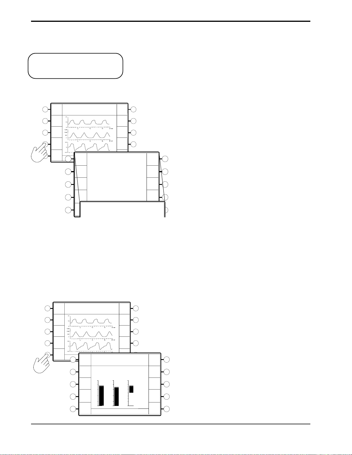
10-4
10.2.3 D
ISPLAYING SYSTEM
INFORMATION
NOTE: In the U.S., the “optional”
alarm package is installed in all Vision
models.
Error
Messages
P (cm H2O)
Vol (ml)
Test
Alarms
Flow (L/min)
System
Info
Bar
Graph
TOTAL OPERATING TIME: 50 HRS
Error
PRESS "MONITORING" TO EXIT
Messages
Test
Alarms
System
Info
OPERATING IN: S/T
1. Software Version: 9.4
2. Oxygen Module: Yes
3. Alarm Module: Standard Alarms
1. Software Version: 9.4
2. Oxygen Module: Yes
3. Alarm Module: Standard Alarms
System Information provides the following information:
• The installed software version
• Verifies the installation of the oxygen module
• The alarm package that is installed.
— Press the System Info soft key.
Time at P
49
hrs
Reset
Brightness
Contrast
Invert
Time at P
49
Reset
Brightness
Contrast
hrs
The display lists the system information.
NOTE: A “NO” response in the Oxygen Module line may
mean that the module is not functional.
The Alarm Module line will display “Optional Alarm
Invert
Module” if the optional alarm module is installed.
10.2.4 CHANGING THE GRAPHIC
DISPLAY
Error
Messages
P (cm H2O)
Vol (ml)
Test
Alarms
Flow (L/min)
System
Info
Bar
Graph
TOTAL OPERATING TIME: 50 HRS
PRESS "MONITORING" TO EXIT
Messages
Alarms
System
Waveform
Error
Test
Info
OPERATING IN: S/T
P
(cm H2O)
20
1500
16
1200
12
900
8
600
4
300
0
TOTAL OPERATING TIME: 50 HRS
PRESS "MONITORING" TO EXIT
0
You may choose to display the Pressure, Volume, and Flow as waveforms or as
bar graphs.
— Press the Bar Graph soft key.
Time at P
49
hrs
Reset
Brightness
Contrast
Invert
Vol
100
(ml) (L/min)
66
33
0
-33
-66
-100
OPERATING IN: S/T
Flow
Time at P
49
Reset
Brightness
Contrast
Invert
The Pressure, Volume, and Flow data are displayed as bar
hrs
graphs. The Bar Graph soft key Descriptor changes to
“Waveform”.
To return to the waveforms, press the Waveform soft key.
BiPAP Vision Clinical Manual
Page 92

10-5
10.2.5 RESETTING THE TIME AT
PRESSURE
P (cm H2O)
Vol (ml)
Flow (L/min)
Time at P
49
Reset
Brightness
Contrast
Invert
Error
Messages
P (cm H2O)
Vol (ml)
Test
Alarms
System
Flow (L/min)
Info
Bar
Graph
TOTAL OPERATING TIME: 50 HRS
PRESS "MONITORING" TO EXIT
Error
Messages
Test
Alarms
System
Info
OPERATING IN: S/T
The Time at Pressure records the total time of therapy. The timer only operates
when spontaneous or timed breaths are present, and can only be reset manually.
The display updates on the hour only.
The Time at Pressure is displayed in the descriptor when you select the Options
screen.
— To reset the timer, press the Time at P soft key from the Options screen.
hrs
The hours are reset to 0.
OPERATING IN: S/T
Time at P
0
Reset
Brightness
Contrast
Invert
hrs
Bar
Graph
10.2.6 ADJUSTING THE
DISPLAY
Error
Messages
P (cm H2O)
Vol (ml)
Test
Alarms
Flow (L/min)
System
Info
Bar
Graph
TOTAL OPERATING TIME: 50 HRS
PRESS "MONITORING" TO EXIT
TOTAL OPERATING TIME: 50 HRS
PRESS "MONITORING" TO EXIT
The display options include the brightness, contrast, and invert options.
— Press the soft key corresponding to the option you wish to modify.
Time at P
49
hrs
Reset
OPERATING IN: S/T
Brightness
Brightness
Contrast
Contrast
Invert
• For Brightness and Contrast, turn the adjustment knob to change
the screen brightness or contrast.
• For Invert, the screen colors reverse when you press the Invert
soft key.
Invert
BiPAP Vision Clinical Manual
Page 93

10-6
10.2.7 TOTAL OPERATING TIME
10.2.8 R
ETURNING TO THE
MONITORING SCREEN
OPERATING IN: S/T
IPAP
15
cm H2O
EPAP
6
cm H2O
Rate
12
BPM
Time at P
49
hrs
Reset
Brightness
Contrast
Invert
MODE: S/T MONITORING
P (cm H2O)
Vol (ml)
Flow (L/min)
V
T
1000
ml
MinVent
Error
Messages
P (cm H2O)
Vol (ml)
Test
Alarms
Flow (L/min)
System
Info
Bar
Graph
TOTAL OPERATING TIME: 50 HRS
PRESS "MONITORING" TO EXIT
The “Total Operating Time” shown in the Data Display Area is a time meter
that runs when the Start/Stop Switch is in the START position. The time is
stored when the Vision ventilator is stopped, and does not reset.
— When you have completed the desired modifications, press the
MONITORING hard key to return to the Monitoring screen.
%O
2
set
55
%
PS = 9
cm H2O
Standby
Options
PIP
15
cm H2O
14
L/min
NOTE: If no user interaction occurs for a 3-minute time span, the unit defaults to the Monitoring screen.
BiPAP Vision Clinical Manual
Page 94

Chapter 11: Modifying Graphic Displays
11-1
11.1Overview
IPAP
EPAP
Rate
15
cm H2O
6
cm H2O
12
BPM
The Vision unit provides real-time Pressure, Volume, and Flow graphics on all
screens. The graphics can be displayed as waveforms or as bar graphs. See
Chapter 10 for instructions to change the graph type. Figure 11-1 illustrates the
waveform graphics. Figure 11-2 illustrates the bar graphics.
This chapter describes the methods of modifying the Pressure, Volume, Flow,
and Time scales. It also describes how to freeze and unfreeze the graphics.
MODE: S/T MONITORING
P (cm H2O)
Vol (ml)
Flow (L/min)
PS = 9
cm H2O
set
%O
55
2
%
Pressure
Waveform
Volume
Waveform
Flow
Waveform
IPAP
EPAP
Rate
V
T
15
cm H2O
6
cm H
12
BPM
700
ml
MinVent
Figure 11-1. Real-time Waveforms.
MODE: S/T MONITORING
O
2
P
(cm H2O)
20
16
12
8
4
0
V
T
1000
1500
1200
900
600
300
ml
14
L/min
Vol
(ml) (L/min)
0
MinVent
14
100
66
33
-33
-66
-100
L/min
PIP
0
15
PS = 9
Flow
cm H2O
PIP
cm H2O
15
Options
cm H2O
%O
2
set
55
Options
%
Pressure
Bar
Volume
Bar
Flow
Bar
Figure 11-2. Real-time Bar Graphs.
BiPAP Vision Clinical Manual
Page 95

11-2
NOTE: All modifications described in this chapter, except the Time Base adjustment, apply to both the waveform
display and the bar graph display.
11.2 Modifying the Display Graph Scales
The Vision unit allows you to modify the scale of the Pressure, Volume, and
Flow graphs and the Time Base.
— Press the SCALE hard key.
IPAP
MODE: S/T MONITORING
15
cm H2O
EPAP
6
O
cm H
2
Rate
12
BPM
V
T
1000
P (cm H2O)
Vol (ml)
Flow (L/min)
ml
MinVent
14
L/min
8
8
%O
2
set
55
cm H2O
15
cm H2O
P (cm H2O)
Vol (ml)
Flow (L/min)
%
Standby
Options
PS = 9
PIP
MODE: S/T MODIFY SCALE
11.2.1 MODIFYING THE SCALES
The Modify Scale screen is displayed.
The following scales are active:
• Pressure
• Volume
• Flow
• Time Base
Flow
Time
Base
P
Vol
You may modify the scales in any order.
STEP 1 Press the soft key corresponding to the scale
you wish to change.
MODE: S/T MODIFY SCALE
8
8
P (cm H2O)
Vol (ml)
Flow (L/min)
Pressure
P
The selected scale is highlighted for change.
Volume
Vol
Flow
Flow
Time Base
Time
Base
BiPAP Vision Clinical Manual
Page 96

STEP 2 Turn the adjustment knob as needed.
Pressure Scale
11-3
40
20
0
50
0
50
-
P (cm H2O)
Vol (ml)
Flow (L/min)
Volume Scale
Flow Scale
Increment: 5 cm H2O
Full Scale Range: 0 cm H2O to
50 cm H2O
Increment: 500 ml
Full Scale Range: 0 ml to
4000 ml
Increment: 50 L/min
Full Scale Range: -300 L/min to
+300 L/min
NOTE: The Time Base adjustment
simultaneously adjusts the time base
scale of all waveforms.
Flow (L/min)
Time Base
Increment: 3 seconds
Full Scale Range: 3 sec to 24 sec
15
BiPAP Vision Clinical Manual
Page 97

11-4
11.2.2 RETURNING TO THE
MONITORING SCREEN
MODE: S/T MODIFY SCALE
8
8
P (cm H2O)
Vol (ml)
Flow (L/min)
— When you have completed the scale modifications press the
MONITORING hard key to return to the Monitoring screen.
P
Vol
Flow
Time
Base
IPAP
MODE: S/T MONITORING
15
cm H2O
EPAP
6
O
cm H
2
Rate
12
BPM
V
T
P
(cm H2O)
Vol
(ml)
Flow
(L/min)
1000
ml
MinVent
14
L/min
PS = 9
%O
2
set
55
%
cm H2O
Standby
Options
PIP
15
cm H2O
NOTE: If no user interaction occurs for a 3-minute time span, the unit defaults to the Monitoring screen.
11.3 Summary of Display Graph Scale
Ranges and Increments
FULL SCALE
PARAMETER
RANGE
INCREMENTS
Pressure Scale
Volume Scale
Flow Scale
Time Scale
5 to 50 cm H2O
0 to 4000 ml
-300 to +300 L/min
3 to 24 sec
BiPAP Vision Clinical Manual
5 cm H2O
500 ml
50 L/min
3 sec
Page 98

11.4Freezing and Unfreezing the Graphs
• Press the FREEZE/UNFREEZE hard key.
IPAP
MODE: S/T MONITORING
15
cm H2O
EPAP
6
O
cm H
2
Rate
12
BPM
Flow
V
T
1000
P
(cm H2O)
Vol
(ml)
(L/min)
ml
MinVent
14
L/min
FREEZE ACTIVE
PS = 9
PIP
15
%O
2
set
55
%
cm H2O
Options
cm H2O
11-5
The graphs stop scrolling but the Data Display Area
remains active and continues to update with each breath.
When the Freeze graph is active, the message “FREEZE
ACTIVE” appears in the Mode/Message Area.
• To unfreeze the graphs, press the FREEZE/UNFREEZE key a second
time. The graphs resume scrolling. The screen is erased and starts a new
scroll from the left.
BiPAP Vision Clinical Manual
Page 99

11-6
BiPAP Vision Clinical Manual
Page 100

Chapter 12: Alarms and Troubleshooting
12-1
12.1Alarms Overview
WARNING: For the following reasons, attention by qualified medical personnel is required whenever a patient is
attached to a ventilator:
This chapter describes the alarm parameters, how to troubleshoot alarm
conditions, and how to troubleshoot mask problems.
The Vision unit contains two types of alarms: System and Adjustable. System
Alarms are integral to the Vision unit to check system operations such as AC
power and internal alarm battery. System Alarms are not adjustable.
Adjustable Alarms are used to monitor patient parameters, such as high
pressure and apnea. These alarms can be adjusted through the Modify Alarms
screen.
The Vision ventilator may be connected from the Nurse Call/Remote Alarm
connector to most hospital call and alarm systems. You must verify whether the
institution’s system is a Normally OPEN or Normally CLOSED circuit. A
Normally OPEN system refers to an alarm system that detects an open circuit in
normal conditions and a closed circuit during alarm conditions. A Normally
CLOSED system detects a closed circuit in normal circumstances and an open
circuit during alarm conditions. The Vision unit is manufactured with a
Normally OPEN configuration. The Vision unit may be changed to interface
with either system. Refer to the BiPAP Vision Service Manual for details.
a. Some malfunctions require immediate corrective action.
b. No monitor, or any combination of monitors, can give absolute assurance of warning in the event of
any and every form of malfunction of the ventilator or gas delivery system. A trained caregiver should
be able to respond in a timely manner to alarm conditions. The attention level required when a patient is
attached to an assist ventilator must be determined by the physician based on the requirements of the
patient.
WARNING: The Adjustable Alarm settings should be reevaluated whenever a change in settings is made on the
ventilator.
NOTE: The alarm test should be performed before using the ventilator, and should be verified daily. Verify that both
the audible and visual alarm indicators are active during the alarm test. If either component is not active, have
the ventilator serviced.
BiPAP Vision Clinical Manual
 Loading...