

Page 1
S/T
atient Guide
Page 2
1004221
JR 3/15/01
Page 3

Contents
Warnings, Cautions, and Notes .................................................................... 3
Warnings ............................................................................................................................................................ 3
Cautions............................................................................................................................................................. 4
Temperatures ..................................................................................................................................................... 4
Intended Use/Indications for Use ....................................................................................................................... 5
Contraindications ...............................................................................................................................................5
1 Contents of the Package...........................................................................6
2 Introduction to the Harmony S/T.............................................................. 7
What is Bi-Level Ventilation?..............................................................................................................................7
What is the Harmony S/T? ................................................................................................................................. 8
Symbols .............................................................................................................................................................9
How to Contact Respironics............................................................................................................................... 9
3 A Tour of the Harmony S/T ..................................................................... 10
Overview .......................................................................................................................................................... 10
Top Panel ......................................................................................................................................................... 11
Connecting the Breathing Circuit .....................................................................................................................12
Rear Panel ....................................................................................................................................................... 12
1
S/T Patient Guide
Page 4

2
4 Using the Harmony S/T ........................................................................... 13
Installing the Inlet Filters .................................................................................................................................. 13
Where to Place the Harmony S/T Unit ............................................................................................................. 14
Connecting the Breathing Circuit ..................................................................................................................... 14
Complete Harmony S/T Setup ......................................................................................................................... 16
Plugging the Unit In (Using AC Power) ............................................................................................................ 17
Using DC Power...............................................................................................................................................17
Starting the Harmony S/T Unit ......................................................................................................................... 18
Adjusting the Rise Time ................................................................................................................................... 18
5 Alarms and What to Do............................................................................. 19
6 Troubleshooting ...................................................................................... 23
Mask Discomfort and Corrective Actions ......................................................................................................... 24
7 Cleaning the Unit and Filters ................................................................... 27
Cleaning Your Harmony Unit ............................................................................................................................ 27
Cleaning/Replacing the Inlet Filters ................................................................................................................. 28
8 Using Oxygen with your Harmony Ventilator ....................................... 30
Limited Warranty.......................................................................................... 35
S/T Patient Guide
Page 5

Warnings, Cautions, and Notes
Warnings
A Warning indicates the possibility of injury to you or the
operator of the device.
• This manual serves as a reference. The instructions in
this manual are not intended to supersede the
instructions of your care giver.
• The Harmony S/T ventilator is not intended to provide
the total ventilatory requirements of the patient.
• The prescribed patient settings must be adjusted by
trained and authorized personnel only. Do not attempt
to open the top lid of the unit.
• Use only the patient circuit provided by your home
care provider.
• When using a patient circuit that contains a Whisper
Swivel® II or other exhalation device, do not tape, seal,
or otherwise block the vent openings. Doing so may
result in asphyxia.
• Oxygen supports combustion. Oxygen should not be
used while smoking or in the presence of an open flame.
• Exercise caution when using the Harmony S/T ventilator
if the room temperature is greater than 95 °F (35 °C). At
high room temperatures, the air from the unit can cause
discomfort or irritation to your nasal passages and your
airway.
• Do not use the Harmony S/T if the breathing circuit
connection is blocked.
• When the Harmony S/T ventilator is used with a
humidifier, be sure that the humidifier is lower than both
the unit and you.
• Repairs and adjustments must be performed by
Respironics-authorized service personnel ONLY.
Service done by inexperienced, unqualified personnel or
installation of unauthorized parts could cause injury,
invalidate the warranty, or result in costly damage.
• Periodically inspect electrical cords for damage or signs
of wear.
• To avoid electrical shock, unplug the Harmony S/T unit
before cleaning it.
• Immediately report any unusual chest discomfort,
shortness of breath, or severe headache to
your physician.
• If the unit is dropped or if you notice any changes in the
operation, contact your home care provider.
3
WARNINGS
S/T Patient Guide
Page 6

4
Cautions
A Caution indicates the possibility of damage to the device.
Cautions, Notes
• Federal law restricts this device to sale by or on the order
of a physician.
• Do not expose the Harmony S/T ventilator to temperatures at or near the extremes of those shown below. If
exposure to such temperatures has occurred, allow the
unit to come to room temperature before turning it on.
Temperatures
Operating: 5 °C to 40 °C
Transport/Storage: -20 °C to 60 °C
• The unit must be positioned on its base for
proper operation.
• Do not place the unit such that any side or the bottom of
the unit may not have adequate air circulation.
• A properly installed, undamaged inlet filter is required
for proper operation.
• Never place liquids on or near the Harmony S/T unit.
• If the External Battery Discharged Alarm is activated,
disconnect the external battery immediately. A discharged battery may be damaged if it continues to be
connected to the ventilator.
Additional Warnings, Cautions, and Notes are
located throughout this manual.
S/T Patient Guide
Page 7

Intended Use/Indications for Use
The BiPAP Harmony S/T is a non-invasive, pressure
support ventilator used to augment the breathing of
patients suffering from acute or chronic respiratory
insufficiency, or to maintain airway patency and provide
ventilatory support to patients who experience obstructive
sleep apnea.
It is not intended to provide the total ventilatory
requirements of the patient.
The Harmony S/T is intended for use in the home,
hospital, or other institutional settings.
Contraindications
The Harmony S/T ventilator should not be used if you
have severe respiratory failure without a spontaneous
respiratory drive.
If any of the following conditions apply to you, consult
your physician before using the Harmony S/T ventilator.
Consult your physician if you have:
• the inability to maintain a patent airway or adequately
clear secretions.
• a risk of aspiration of gastric contents.
• acute sinusitis or otitis media.
• an allergy or hypersensitivity to the mask materials
where the risk
from allergic reaction outweighs the benefit of ventilatory assistance.
• epistaxis.
• hypotension.
The following are potential side effects of noninvasive
positive pressure therapy:
• Ear discomfort
• Conjunctivitis
• Skin abrasions due to noninvasive interfaces
• Aerophagia (gastric distention)
5
Intended Use, Contraindications
S/T Patient Guide
Page 8
6
Package Contents
1 Contents of the Package
The BiPAP Harmony S/T package contains:
• BiPAP Harmony S/T unit
• Six feet of tubing
• Whisper Swivel II exhalation port
• Gray Foam filter
• Ultra-fine filter
Your home care provider should have pre-assembled the
tubing, exhalation port, and mask into a breathing circuit.
If any of the items are missing, please contact your home
care provider.
OPTIONS
• DC power cord
• Oxygen valve (required for oxygen use)
• Bacteria filter
• Humidifier
Harmony S/T Unit
Disposable
Ultra-fine Filter
Six Feet of
Tubing
Exhalation
Port
Reusable Gray
Foam Filter
S/T Patient Guide
Page 9
2 Introduction to the Harmony S/T
7
What is Bi-Level Ventilation?
Bi-level ventilation with the Harmony S/T Ventilatory
Support System helps you to breathe by supplying two
levels of air pressure. The Harmony S/T provides a higher
pressure—known as IPAP (Inspiratory Positive Airway
Pressure)—when you inhale, and a lower pressure—
known as EPAP (Expiratory Positive Airway Pressure)—
when you exhale. The higher pressure opens your airway
to increase the amount of air going into your lungs, and the
lower pressure makes it easier for you to exhale while still
keeping your airway open.
NOTE:Occasionally, cosmetic changes may be made to
the product that do not affect the performance or
specifications of the product. These kinds of
changes do not warrant a reprinting of this
manual. Illustrations are for reference only.
The Harmony Ventilator Provides
Two Levels of Ventilation.
IPAP
Pressure
Introduction
EPAP
Pressure
Figure 2-1. BiPAP Breathing Levels.
S/T Patient Guide
Page 10
8
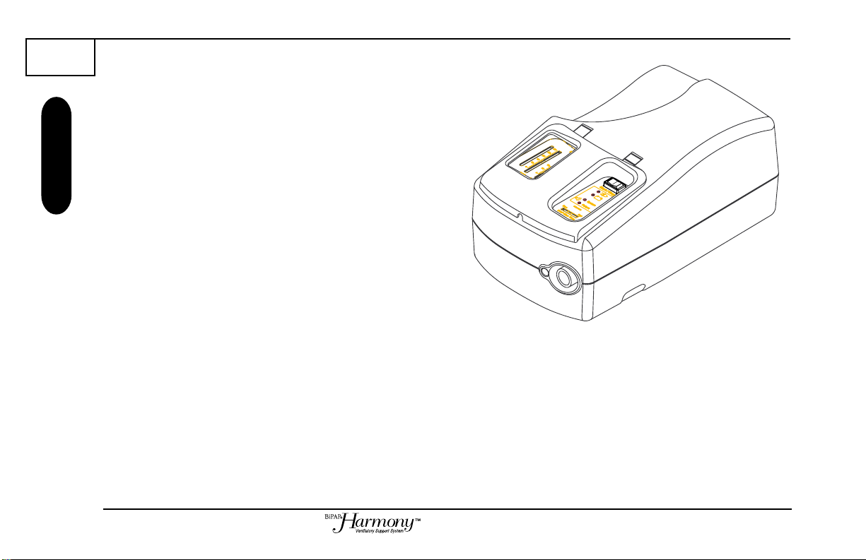
What is the Harmony S/T?
Introduction
The Harmony ventilator, shown in Figure 2-2, supplies
two levels of air pressure through a breathing circuit. The
circuit consists of:
• circuit tubing to deliver the air from the ventilator to
your interface (e.g., mask)
• an exhalation port to vent exhaled air from the circuit
• a mask or other interface to deliver the ventilation to
your nose or nose and mouth, depending on which
interface has been prescribed for you
The system senses your breathing effort and changes
pressure levels when you inhale and exhale.
Figure 2-2. The Harmony S/T Unit.
S/T Patient Guide
Page 11
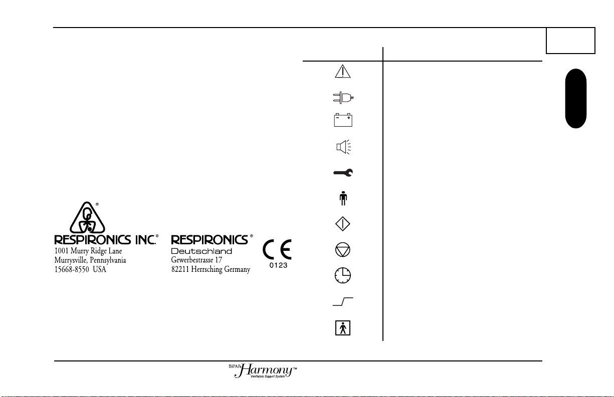
Symbols
The symbols shown at right are used on the Harmony S/T
and throughout this manual.
How to Contact Respironics
Symbol Meaning
Attention, consult accompanying documents
AC Power Indicator
DC Power Indicator
9
Symbols
To have your unit serviced, contact your home care
provider. If you need to contact Respironics directly, use
the following addresses:
Alarms
System Alarm Indicator
Patient Alarm Indicator
START
STOP
Time at Pressure
Rise Time control (patient comfort)
Type BF
S/T Patient Guide
Page 12
10
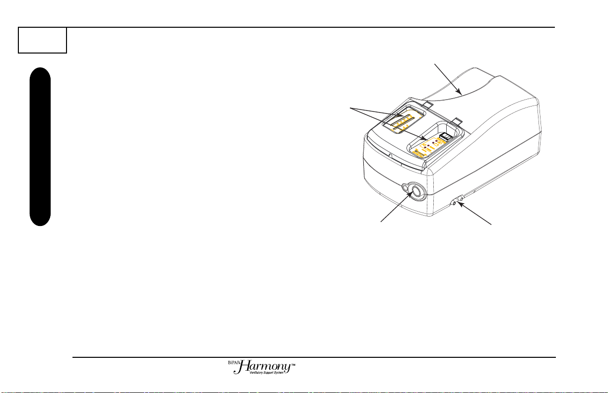
3 A Tour of the Harmony S/T
Overview
Tour of the Harmony S/T
Figure 3-1 shows the location of the:
Carrying
Handle
• controls and indicators
• breathing circuit connection
• carry handle
Controls/
Indicators
Breathing Circuit
Connection
Figure 3-1. The Harmony S/T Front and Top.
S/T Patient Guide
Optional Oxygen
Valve
Page 13

Top Panel
The top panel contains the controls and indicators you will
need when you are using the BiPAP Harmony S/T.
• Start/Stop switch
• AC Power Indicator
• DC Power Indicator
• Patient Alarm
• System Alarm
• Rise Time control
Pressure
Indicator
Start/Stop
Switch
Power
Indicators
Alarm
Indicators
11
Top Panel
¤
Rise Time
Control
The Start/Stop switch starts and stops the unit.
The AC and DC power indicators show you whether the
Harmony S/T is connected to AC or DC power.
The Patient and System alarms alert you when a problem
occurs. See Chapter 5 for an explanation of what to do
when an alarm is activated.
The Rise Time control adjusts the time the pressure takes
to go from the lower-level pressure (EPAP) to the
higher-level pressure (IPAP). You adjust this control for
your comfort.
Figure 3-2. The Harmony S/T Top Panel.
The controls and indicators contained within the dotted
line in Figure 3-2 are covered by a door that prevents the
settings from being accidentally changed. Your home care
provider has set the controls according to
your prescription.
The Pressure Indicator and the IPAP and EPAP slides are
visible through the window of the door. The Pressure
Indicator shows the approximate pressure level produced.
The IPAP and EPAP slides light when the unit is in the
respective phase of therapy.
S/T Patient Guide
Page 14

12
Connecting the Breathing Circuit
Figure 3-3 shows where the circuit tubing connects to the
Harmony S/T unit.
Circuit Connections, Rear Panel
Rear Panel
Figure 3-4 shows the location of the:
• air inlet filters
• AC inlet
• DC inlet
The Harmony S/T uses a gray pollen filter that is
washable and reusable, and a white ultra-fine filter that
is disposable.
The AC Inlet is where the AC receptacle is connected if
you are running the unit from house voltage.
The DC Inlet is where the DC plug is connected if you are
running the unit from a 12 Vdc source.
Patient
Interface
Port
Figure 3-3. Breathing Circuit Connection.
DC Cord
Retainer
DC Inlet
Filter Access
Panel
Figure 3-4. Rear Panel.
AC Inlet
S/T Patient Guide
Page 15

4 Using the Harmony S/T
Installing the Inlet Filters
The Harmony uses a gray foam filter that is reuseable, and
an optional white ultra-fine filter that is disposable. One
filter of each kind is supplied with Harmony.
If your home care provider did not install the inlet filters,
you must install at least the gray foam filter before using the
Harmony.
STEP 1 Place the pollen filter on top of the
ultra-fine filter.
STEP 2 Slide the filters into the air inlet at the rear of the
unit.
STEP 3 Place the bottom of the inlet filter cover into the
bottom of the air inlet opening, making sure that
the catches engage the lip of the opening.
STEP 4 Swing the top of the cover into place and press
down on it to engage the cover catches in the air
inlet opening.
Reusable Pollen
Filter
Disposable Ultra-fine
Filter
Inlet Filter
Cover
13
Installing the Air Filters
See Chapter 7 for instructions to clean or replace the filters.
S/T Patient Guide
Page 16

14
Placing the Harmony S/T for Use
Where to Place the Harmony S/T Unit
Place the Harmony S/T unit on its base somewhere within
easy reach of where you will be using it. Make sure that
the air inlet on the rear of the unit is not blocked. If you
block the air flow around the unit, the unit may not work
properly.
If you are using a humidifier, be sure to place the
humidifier and unit on a placemat or other waterproof
material to protect your furniture from moisture. Both you
and the Harmony S/T ventilator MUST be positioned
higher than the humidifier to prevent the backflow of water
into the unit or into your mask.
Circuit
Tubing
Connecting the Breathing Circuit
STEP 1 Connect one end of the six-foot tubing to the
large connector on the Harmony unit.
STEP 2 Connect the open end of the circuit tubing to the
exhalation device.
S/T Patient Guide
Exhalation
Device
Step 1
Circuit
Tubing
Step 2
Page 17

STEP 3 Connect the exhalation device to the mask
Exhalation
Device
Mask
Connector
Mask or
Other
Interface
connector.
15
STEP 4 Attach the Softcap
see the instructions that came with your Softcap
or headgear.
®
or headgear to the mask—
Step 3
Connecting the Breathing Circuit
S/T Patient Guide
Page 18

16
Circuit
Tubing
Exhalation
Port
Patient
Interface
(typical)
Complete Harmony S/T Setup
Complete Setup
Figure 4-1 shows the completed breathing circuit setup for
the Harmony S/T unit.
Figure 4-1. Harmony S/T Complete Breathing Circuit.
S/T Patient Guide
Page 19

Plugging the Unit In (Using AC Power)
STEP 1 Plug the receptacle end of the AC cord into the
AC inlet.
STEP 2 Insert the plug end of the AC cord into the wall
outlet.
WARNING: Never plug the Harmony S/T AC cord into
an outlet that is controlled by a
wall switch.
If the External Battery Discharged Alarm is activated,
disconnect the external battery immediately. A discharged
battery may be damaged if it continues to be connected to
the ventilator.
Using DC Power
STEP 1 Plug the receptacle end of the DC cord into the
DC inlet.
STEP 2 Leaving some slack in the DC cord, push the
DC cord into the DC cord retainer.
STEP 3 Insert the adaptor end of the DC cord into the
appropriate DC outlet. See the instructions that
came with the DC cord for proper DC
connections.
DC Cord
Retainer
17
Plugging the Unit In
S/T Patient Guide
Page 20

18
Starting the Harmony S/T Unit
STEP 1 Press the Start/Stop switch to the START
Starting the Unit
STEP 2 Allow the unit to establish flow and then put on
NOTE: If the unit does not sound the two beeps or
illuminate the indicators, do not try to use the
unit. Contact your home care provider.
STEP 3 Make sure that no air is leaking from your mask
STEP 4 If you are using the Harmony while sleeping,
NOTE: A small amount of mask leak is normal and
acceptable. Large mask leaks or eye irritation
from an air leak should be corrected as soon as
possible.
position. The unit will sound two beeps and
briefly illuminate all the indicators. This is the
internal test performed by the unit.
your mask assembly.
into your eyes. If it is, adjust the mask and
Softcap or headgear until air stops leaking into
your eyes. See the instructions that came with
your mask.
place the tubing from the Harmony unit over
your headboard to reduce tension on the mask.
STEP 5 Relax. Take slow, relaxed breaths through
your nose.
NOTE: If you are having trouble with your mask, see
Chapter 6 for some suggestions.
Adjusting the Rise Time
The Rise Time is the time it takes for the Harmony to
change from EPAP to IPAP (See Chapter 2). You can
adjust this time to meet your comfort needs by moving the
Rise Time control (See Figure 3-2). The control changes
from a faster rise time on the left to a slower rise time on
the right.
S/T Patient Guide
Page 21

5 Alarms and What to Do
This chapter describes the Harmony S/T alarms and what
you should do if an alarm is activated.
The Harmony S/T unit provides two types of alarms,
System and Patient. Both types are indicated by visual and
audible alarms. The visual alarms are LEDs located on the
right side of the front panel, as shown in Figure 5-1.
If an alarm sounds, check which LED is on and refer to the
table on the next page for an explanation and possible
corrective actions. If the suggested actions do not stop the
alarm, contact your home care provider.
Symbol Meaning
Off
On
Flashing
Figure 5-1. Alarm Indicator Locations.
19
System Alarm
LED
Alarms
Patient Alarm
LED
S/T Patient Guide
Page 22

20
DC LED On
AC LED On
System LED On
Continuously
Patient LED Off
OR
DC LED On
AC LED On
System LED On
Continuously
Patient LED Off
OR
WHA T YOU SEE WHAT YOU HEAR
WHAT THE UNIT
DOES
WHY THE ALARM
SOUNDED
WHAT TO DO
Alarms
AC LED Off
DC LED Off
System LED On
Continuously
Patient LED Off
Continuous Tone
Continuous Tone
Intermittent Beeps
Unit not working
Unit not working
Unit is operating
S/T Patient Guide
Loss of input power
Internal failure
Unable to reach
prescription
Be sure that the AC
power cord is plugged
into a working outlet
or the DC power cord
is connected to a
charged battery.
Contact your home
care provider for
service.
Check the inlet filters
as described in
Chapter 7. If the
filters are OK, contact
your home care
provider for service.
Page 23

WHAT YOU SEE WHAT YOU HEAR
DC LED Off
AC LED Off
WHAT THE UNIT
DOES
WHY THE ALARM
SOUNDED
WHAT TO DO
21
AC LED On
OR
DC LED On
System LED On
Continuously
Patient LED Off
AC LED Off
DC LED Off
System LED On
Continuously
Patient LED Off
System LED Off
Patient LED On
Intermittent Beeps
Intermittent Beeps
Intermittent Beeps
Three beeps every 30
seconds
Unit not working
Unit not working
Unit is operating
Unit is operating
Internal Failure
External battery
discharged
Patient Disconnect
AC and DC power
sources were both
connected and AC
power was lost while
the ventilator was
running
Contact your home
care provider for
service.
Alarms
Check the external
battery or seek an
alternate power
source.
Be sure that the
breathing circuit and
mask are connected
properly.
Reconnect the AC
power and restart the
unit, or disconnect the
AC power cord and
restart the unit so that
it runs from DC.
S/T Patient Guide
Page 24

22
WHAT YOU SEE WHAT YOU HEAR
WHAT THE UNIT
DOES
WHY THE ALARM
SOUNDED
WHAT TO DO
Alarms
AC LED Off
DC LED Flashing
Three beeps every 15
seconds
Unit is operating
Low external battery
The external battery is
about to fail. Seek an
alternate power
source.
S/T Patient Guide
Page 25

6 Troubleshooting
This chapter lists problems you could experience with
your Harmony unit or mask, and presents possible
solutions.
23
PROBLEM
The air out of the mask is much
warmer than usual.
Pressure delivery shown by the
pressure bar graph is much less than
the setting on the IP AP or EPAP
controls.*
No air flow from the unit when the
power switch is placed in the START
position.
*The pressure bar graph is not intended to be an accurate indicator of the pressure level. However, it should not be off by
a large amount.
WHY IT HAPPENED
Inlet filters may be dirty.
Inlet filters may be dirty.
Problems in the Harmony S/T unit.
WHAT TO TRY
Clean or replace the inlet air filters as
described in Chapter 7. If the problem
persists, contact your home care
provider.
Clean or replace the inlet air filters as
described in Chapter 7. If the problem
persists, contact your home care
provider.
Contact your home care provider for
service.
S/T Patient Guide
Troubleshooting
Page 26

24
Mask Discomfort and Corrective Actions
Mask Problems
Problem
Mask feels uncomfortable to wear.
Significant air leakage around the
mask
Redness occurs when the mask
cushion or Comfort Flap® mask
accessory comes in contact with
the skin.
Why it Happened
1. Improper Softcap or headgear
adjustment.
2. Improper mask fitting.
1. Improper Softcap or headgear
adjustment.
2. Improper mask fitting.
1. Improper mask fitting.
2. Improper mask cleaning.
What to Try
Check the Softcap or headgear
adjustment as described in the
Softcap or headgear instructions.
Contact your home care provider for
a refitting or a different size of mask.
Check the Softcap or headgear
adjustment as described in the
Softcap or headgear instructions.
Contact your home care provider for
a refitting or a different size of mask.
Contact your home care provider for
a refitting or a different size of mask.
Be sure to thoroughly rinse after
cleaning to remove residue. See the
mask cleaning instructions.
S/T Patient Guide
Page 27

25
Problem
Redness occurs when the mask
cushion or Comfort Flap® mask
accessory comes in contact with
the skin.
Sore or dry eyes
Runny nose
Why it Happened
3. Irritation or allergic reaction to
mask material.
1. Mask not positioned properly.
2. Improper mask fitting.
Nasal reaction to air flow.
What to Try
Use a barrier between your skin and
the mask, such as 3M’ s Microfoam
or Squibb’s Duoderm®.
Check the Softcap or headgear
adjustment as described in the
Softcap or headgear instructions.
Contact your home care provider for
a refitting or a different size of mask.
Call your doctor.
®
Mask Problems
S/T Patient Guide
Page 28

26
Problem
Why it Happened
What to Try
Mask Problems
Throat or nose dryness
Nasal, sinus or ear pain
1. Air is too dry.
2. Improper mask fitting.
Sinus or middle ear infection
1. Increase the room humidity.
2. Consult with your doctor or home
care provider about using a
Respironics humidifier with the
ventilator.
Stop using the Harmony S/T
ventilator and contact your doctor.
S/T Patient Guide
Page 29

7 Cleaning the Unit and Filters
Cleaning Your Harmony Unit
Before cleaning or performing any routine maintenance,
always switch the start/stop switch to and
disconnect the unit from the power source.
NOTE: The following cleaning instructions are for the
Harmony unit only. To clean the circuit and
accessories, refer to each accessory’s instruction
sheet.
WARNING: Do not immerse the Harmony unit or allow
any liquid to enter the cabinet or
inlet filter.
Clean the unit with a cloth dampened with water and a
mild detergent, or with 70% Isopropyl Alcohol only.
27
Cleaning and Maintenance
S/T Patient Guide
Page 30

28
Inlet Filters
Cleaning/Replacing the Inlet Filters
The Harmony unit has two removable filters at the air
inlet. The gray foam filter is washable and reusable. The
optional white ultra-fine filter is disposable.
CAUTION: Dirty inlet filters may cause high operating
temperatures and may affect ventilator
performance. Periodically examine the
inlet filters for integrity and cleanliness.
Step 1 Turn the Harmony unit start/stop switch to the
STOP position and disconnect the power cord
from the wall outlet.
Step 2 Remove the filter panel by pressing down on
the top of the panel to release the tabs, then
swinging the panel out from the unit’s body.
Step 3 Remove the filters from the enclosure. The top
filter is the reusable gray foam filter. The
bottom filter is the optional disposable white
ultra-fine filter.
Step 4 Check the filters to see if they are dirty or torn.
Reusable Gray
Foam Filter
S/T Patient Guide
Step 2
Disposable Ultra-fine
Filter
Step 3
Page 31

Step 5 If needed, wash the gray foam filter in warm,
soapy water. Rinse the filter thoroughly to
remove all soap residue. Allow the filter to
completely dry before reinstalling it. Use the
extra gray foam filter that was supplied with
your Harmony unit while the wet filter dries. If
the gray foam filter is torn, replace it.
29
Step 6 If the ultra-fine filter is dirty or torn, replace it.
Step 7 Replace the filters with the ultra-fine filter on
the bottom.
Step 8 Replace the filter panel.
Contact your home care provider to order filters.
NOTE: To clean the patient circuit accessories, refer to
each accessory’s instruction sheet.
Inlet Filters
S/T Patient Guide
Page 32

30
8 Using Oxygen with your
Harmony Ventilator
Using Oxygen
If your doctor has prescribed oxygen to be used with your
Harmony S/T, follow these instructions to connect oxygen
to the breathing circuit.
WARNING: If you are using oxygen, your Harmony
WARNING: Oxygen supports combustion. Oxygen
Oxygen tubing from the oxygen valve can be connected
either to the mask or to an oxygen enrichment adaptor. If
using the adaptor, you must place it in the breathing circuit
between the air outlet of the Harmony S/T unit and the
breathing circuit tubing.
S/T must be equipped with the optional
oxygen valve, shown in Figure 8-1 .
Failure to use the oxygen valve could
result in a fire hazard. Contact your home
care provider if you require oxygen, but an
oxygen valve has not been supplied on the
ventilator.
should not be used while smoking or in
the presence of an open flame.
Optional Oxygen
Valve
Figure 8-1. Optional Oxygen Valve.
S/T Patient Guide
Page 33

Step 1 As shown in Figure 8-2, attach oxygen tubing
to the rear oxygen valve port. The oxygen
valve prevents oxygen from entering the
Harmony S/T enclosure when the unit
is stopped.
31
Step 2 Connect another section of oxygen tubing to
the front valve port, then to the oxygen
enrichment adaptor in the breathing circuit or
to one of the sample ports on the mask.
Step 3 Turn the Harmony S/T ventilator on before
turning on the oxygen supply.
Step 4 Turn the oxygen flow on.
Circuit
Tubing
Oxygen
Enrichment
Attachment
Oxygen
Valve
From Oxygen
Source
Figure 8-2. Attaching oxygen tubing to the Harmony S/T.
Exhalation
Port
Oxygen Tubing
from Oxygen
Shut-Off Valve
Figure 8-3. Attaching oxygen tubing to mask port.
S/T Patient Guide
Using Oxygen
Page 34

32
Index
A
AC Indicator 11
AC Inlet 12
Air Inlet Filters 12
Alarms 19
Patient 11
System 11
What to Do 19
B
Bi-Level Ventilation 7
Breathing Circuit 8
Complete 16
Connection 10, 14
C
Cautions 4
Cleaning and Maintenance 27
Cleaning Your Harmony Unit 27
Cleaning/Replacing the Inlet Filters 28–29
Comfort control 11
Contents of Package 6
Contraindications 5
D
DC Indicator 1 1
DC Inlet 12
E
EPAP 7
EPAP control 11
Exhalation Port 15
Expiratory Positive Airway Pressure 7
F
Filters
Cleaning/Replacing 28–29
H
Harmony S/T Ventilator
Breathing Circuit 8
Cleaning 27
Connections 10
Starting 18
Top Panel 10
Touring 10
S/T Patient Guide
Page 35

What it is 8
Where to Locate 14
I
Indicators
AC 11
DC 11
Inlet Filters
Cleaning/Replacing 28–29
Inspiratory Positive Airway Pressure 7
Installing the Inlet Filters 13
Interface 8
Introduction 7
IPAP 7
IPAP Control 11
L
Limited Warranty 35
Location 14
M
Mask 8
Mask Discomfort
Corrective Action 24
O
Oxygen
Connecting 30
Valve 31
P
Package Contents 6
Patient Alarm 11
Plugging the Unit In 17
Pressure Indicator 11
R
Rear Panel 12
Respironics
How to Contact Us 9
S
Start/Stop switch 11
Starting the Harmony Unit 18
Symbols 9
System Alarm 11
33
S/T Patient Guide
Page 36

34
T
Temperatures
operating, storage 4
Top Panel
Components of 11
Troubleshooting 23
Tubing
Breathing Circuit 6, 12, 14
V
Ventilation, bi-level 7
W
Warnings 3
Warnings, Cautions, and Notes 3
Warranty 35
S/T Patient Guide
Page 37

Limited W arranty
Respironics, Inc. warrants that the BiPAP Harmony S/T System shall be free from defects of workmanship and materials
and will perform in accordance with the product specifications for a period of one (1) year from the date of sale by
Respironics, Inc. to the dealer. If the product fails to perform in accordance with the product specifications, Respironics,
Inc. will repair or replace – at its option – the defective material or part. Respironics, Inc. will pay customary freight
charges from Respironics, Inc. to the dealer location only. This warranty does not cover damage caused by accident,
misuse, abuse, alteration, and other defects not related to material or workmanship.
Respironics, Inc. disclaims all liability for economic loss, loss of profits, overhead or consequential damages which may
be claimed to arise from any sale or use of this product. Some states do not allow the exclusion or limitation of
incidental or consequential damages, so the above limitation or exclusion may not apply to you.
This warranty is given in lieu of all other express warranties. In addition, any implied warranties—including any
warranty of merchantability or fitness for the particular purpose—are limited to one year. Some states do not allow
limitations on how long an implied warranty lasts, so the above limitation may not apply to you. This warranty gives
you specific legal rights, and you may also have other rights which vary from state to state.
To exercise your rights under this warranty, contact your local authorized Respironics, Inc. dealer or contact Respironics,
Inc. at:
1001 Murry Ridge Lane
Murrysville, Pennsylvania 15668-8550
1-412-731-2100
35
S/T Patient Guide
Page 38

36
S/T Patient Guide
 Loading...