

Page 1

Instructions for Use | Introduction
Trilogy Evo Universal Instructions for Use
For Technical Support and Customer Service, contact Philips Customer Service:
USA
Respironics Inc.
1001 Murry Ridge Lane Murrysville, PA 15668
Email: service@philips.com, clinical@philips.com
Web: www.philips.com\healthcare
Authorized European Representative:
Respironics Deutschland GmbH & Co. KG
Gewerbestrasse 17
D-82211 Herrsching Germany
+49 8152 93060
Copyright © 2018 Koninklijke Philips N.V. All rights reserved.
This work is protected under Title 17 of the United States copyright code and is the sole property of Philips Respironics. No part
of this document may be copied or otherwise reproduced, or stored in any electronic information retrieval system, except as
specifically permitted under United States copyright law, without the prior written consent of Philips Respironics.
Trilogy Evo Universal is the registered trademark of Respironics Inc.
The Bluetooth® word mark and logos are registered trademarks owned by Bluetooth SIG, Inc. and any use of such marks by
Philips Respironics is under license.
Dawn Ultra is a registered trademark of Procter & Gamble.
Other trademarks and trade names are those of their respective owners.
Illustrations and screen images in this document are representative depictions.
Page 2

Instructions for Use | Introduction
Contents
1. Introduction ................................................................ 4
Intended Use................................................................... 4
Environments of Use ....................................................... 4
Contraindications ............................................................ 4
Package Contents............................................................ 5
Warnings ......................................................................... 5
Symbols Glossary ............................................................ 9
How to Contact Philips Respironics .............................. 11
2. About Trilogy Evo Universal ...................................... 12
Parts of Trilogy Evo Universal ........................................... 12
Parts of the User Interface ............................................ 14
Monitoring Window ...................................................... 15
3. Therapy Modes and Controls .................................... 17
Overview ....................................................................... 17
Control Modes .............................................................. 19
Spontaneous Modes ..................................................... 21
Mixed Modes ................................................................ 23
Therapy Features .......................................................... 25
Therapy Actions ............................................................ 27
Therapy Control Settings .............................................. 27
Dynamic Therapy Parameters ....................................... 29
4. Device Setup ............................................................. 31
Setup Overview ............................................................. 31
Placement ..................................................................... 31
Connecting AC Power ................................................... 31
Installing Filters ............................................................. 31
Connecting a Circuit ...................................................... 33
Adding Oxygen .............................................................. 35
Starting Trilogy Evo Universal ....................................... 36
5. Device Operation ...................................................... 37
Clinical Assessment ....................................................... 37
Entering New Patient Information ................................ 37
About Prescriptions ...................................................... 37
Starting and Stopping Ventilation ................................. 39
Actions during Ventilation ............................................ 39
6. Alarms and System Messages .................................. 41
Overview ...................................................................... 41
About Alarms ................................................................ 41
The Alarm List ............................................................... 42
Setting and Changing Alarms........................................ 42
Setting the Alarm Volume ............................................ 43
Responding to an Alarm ............................................... 43
Resetting Alarms .......................................................... 43
Alarms and System Messages ...................................... 44
Prescription Alarm Availability by Therapy Mode ........ 60
Testing Alarms .............................................................. 60
Alarm and Event Log .................................................... 63
7. Device Options ......................................................... 65
Device Settings ............................................................. 65
Calibration .................................................................... 66
Data Transfer ................................................................ 68
Information .................................................................. 70
8. Cleaning and Disinfection ......................................... 71
Exterior Cleaning and Disinfection ............................... 71
Cleaning the Detachable Battery .................................. 72
Rinsing the Air-Inlet Foam Filter ................................... 72
External Active Exhalation Valve Cleaning and
Disinfection .................................................................. 73
9. Service and Maintenance ......................................... 75
Service .......................................................................... 75
Disposal ........................................................................ 75
Routine Maintenance ................................................... 75
Replacing the Air-Inlet Foam Filter ............................... 75
Replacing the Particulate Filter .................................... 76
Preparing the Device for a Use by a Different Patient.. 76
10. Trilogy Evo Universal Accessories ......................... 77
Power Accessories ........................................................ 77
Patient Monitors .......................................................... 77
Filters ............................................................................ 80
Patient Circuits ............................................................. 81
Circuit Accessories ........................................................ 81
Dual Limb Active Exhalation Valve ............................... 82
Oxygen ......................................................................... 82
Portability and Travel Accessories ................................ 83
Page 3

Instructions for Use | Introduction
11. Power Management ............................................. 84
Power Sources .............................................................. 84
Battery Power Indicator ................................................ 84
Battery Status Indicator ................................................ 84
AC Power ........................................................................ 84
External Battery ............................................................ 85
Detachable Battery ....................................................... 85
Internal Battery ............................................................. 86
Power Loss .................................................................... 86
Power Indicator Icons ................................................... 86
12. Technical Specifications ........................................ 88
Specifications ............................................................... 88
Standards Compliance .................................................. 91
Pneumatic Diagram ...................................................... 92
EMC Information .......................................................... 92
13. Wireless Connectivity ........................................... 96
Bluetooth Actions ......................................................... 96
NFC Actions .................................................................. 97
Troubleshooting ........................................................... 97
14. Glossary ................................................................ 98
15. Warranty ............................................................ 100
Intended Use 3
Page 4

Instructions for Use | Introduction
1. Introduction
The Trilogy Evo Universal ventilator is a medical device intended for use by qualified, trained personnel under the direction of a
physician according to its technical specifications.
Intended Use
The Trilogy Evo Universal ventilator provides invasive and non-invasive positive pressure ventilation for the care of patients
≥2.5 kg through adults. The ventilator can measure, display, record, and alarm SpO
data when integrated with the appropriate accessories. The ventilator is suitable for use in institutional and hospital settings
and non-emergency transport settings; for example, wheelchair, personal vehicle, or ambulance.
, FiO2, CO2, respiratory rate, and pulse rate
2
Environments of Use
The Trilogy Evo Universal ventilator is intended to be used:
• In institutional environments.
• While attached to a wheelchair, bedrail, gurney, roll stand, or sitting on a flat surface such as a table or nightstand.
• While transporting patients within and between facilities such as automobile or commercial aircraft.
Contraindications
If the patient has any of the following conditions, consult the patient’s health care professional before using noninvasive
ventilation:
• An inability to maintain a patent airway or adequately clear secretions
• At risk to aspirate gastric contents
• Acute sinusitis or otitis media
• Epistaxis, causing pulmonary aspiration of blood
• Hypotension
Page 5

Package Contents
Instructions for Use | Introduction
Warnings
Environmental
• You should not operate Trilogy Evo Universal in the presence of flammable gasses.
• Do not cover the ventilator or place in a position that affects proper operation.
• Do not block the cooling and intake air vents.
• Do not operate Trilogy Evo Universal in an environment that is outside the specified ranges. Using the ventilator outside
of this temperature range or above this altitude can affect the ventilator performance.
• The blower warms the temperature of the airflow. Use of the device at room temperatures warmer than 40˚C may cause
thermal irritation.
• Do not expose the device or detachable battery to temperatures above 60˚ C (140˚ F) during use or above 70˚ C (158˚ F)
during storage. This will reduce battery life and may increase the risk of fire or damage the battery.
• The Trilogy Evo Universal is not intended for MRI or anesthesia applications, and is not intended to be permanently
mounted in EMS vehicles.
• When disposing of this device or any accessories, ensure you comply with your local regulations. Dispose of any
potentially biohazardous waste according to your local regulations.
Warnings 5
Page 6

Instructions for Use | Introduction
• This device is intended for use in the electromagnetic environment specified in the “EMC Information” chapter. Ensure
the environment is compatible. Portable and mobile RF communications equipment, including cables, should be no closer
to any part of the device than the recommended separation distance indicated in the “EMC Information” chapter.
• This device is not made with natural rubber latex.
• Do not use the ventilator in a hyperbaric chamber.
• Do not use the ventilator in the presence of nitric or nitrous oxide.
• Do not use the ventilator with helium or in the presence of mixtures in combination with helium.
• Route all cables in a manner to prevent injury, such as tripping or strangulation, to the patient and caregiver.
Clinical
• Before placing a patient on the ventilator, perform a clinical assessment. Considerations should include:
- Choosing alarm settings
- Whether alternative ventilation equipment is required
- Whether alternative monitors are required, such as Vte monitoring for Active PAP circuit, pulse oximeter or
respiratory monitor with alarm
• Trilogy Evo Universal is a restricted medical device. It is designed for use by respiratory therapists or other trained and
qualified caregivers under the supervision of a physician. Only the supervising physician’s orders authorize changes to the
prescription and other device settings. Before using Trilogy Evo Universal, you must read and understand this manual.
• When using the ActivePAP circuit, CO
80601-2-55.
• U
nintentional leaks cause exhaled volume and expired CO2 values to differ from actual patient values.
• The caregiver or health care professional is responsible for verifying any changes to the device, prescription, or other
settings before applying changes. The caregiver or health care professional is responsible for ensuring settings are correct
and compatible with the patient. Using the wrong prescription for a patient may result in improper therapy, lack of
appropriate safety monitoring, or risk of death or injury to the patient.
monitoring is required to measure exhaled carbon dioxide, in accordance with ISO
2
Alternate Ventilation
• To avoid patient death or serious injury, ventilator-dependent patients require immediate access to alternate ventilation
equipment, such as a back-up ventilator or manual resuscitator.
• Qualified personnel should monitor ventilator-dependent patients continuously. Personnel should be prepared to provide
alternate therapy in the event of ventilator failure or inoperative equipment.
Alarms
• Do not rely on any single alarm to detect a disconnected circuit.
• Respond immediately to any high priority alarm. It may indicate a potentially life-threatening condition.
• Visually monitor the patient and ventilator at all times during an Alarm Silence period. Allowing alarms to continue
without intervention may result in harm to the patient.
• If the high-priority Low Battery alarm occurs, immediately connect the ventilator to an alternate power source. If no
alternate power source is available, immediately place the patient on an alternate source of ventilation.
• When using a remote alarm, make sure you fully test the remote alarm connector and cable by verifying that:
- You can hear the ventilator’s audible alarms on the remote alarm.
- The remote alarm signals when you disconnect the remote alarm cable from the ventilator or from the
remote alarm
• Test the operation of the circuit disconnect function daily and whenever the patient circuit is changed. An increase in
circuit resistance can prevent proper operation of some alarms.
Warnings 6
Page 7

Instructions for Use | Introduction
• Speaking valves, heat moisture exchangers (HMEs), humidifiers, and filters create additional circuit resistance and may
affect the performance of alarms chosen for circuit disconnect protection.
• Do not set the Low Peak Inspiratory Pressure alarm too low, or the system may not detect large circuit leaks or a patient
disconnect.
Accessories
• Use Trilogy Evo Universal only with accessories intended for use with this device. Otherwise, adverse performance
including increased electromagnetic emissions or decreased electromagnetic immunity of this equipment can occur. For a
list of accessories, such as patient interfaces, circuits, exhalation ports, and cables, see the Trilogy Evo Universal
accessories guide. Ensure accessories and parts are compatible before you connect a patient to the device. Consult the
accessory’s instructions before use.
• The air-inlet foam filter is required to protect the ventilator from dirt and dust. See the “Service and Maintenance”
chapter for maintenance instructions.
• Be certain that any breathing system filter used with this device complies with ISO 23328-1 and ISO 23328-2. · To prevent
patient or ventilator contamination, we recommend you use a Respironics-approved main flow bacteria filter (Part
Number 342077) on the patient gas outlet port. Filters not approved by Respironics may degrade system performance.
• When adding any components (such as humidifiers, speaking valves, heat moisture exchangers, and filters) to the
breathing system, consider the flow resistance and dead space in relation to the potential for adverse effects on the
patient’s ventilator management and device alarms.
• Nebulization or humidification can increase the resistance of breathing system filters. Monitor the breathing system
frequently for increased resistance and blockage.
• Gas added by the use of a pneumatic nebulizer can adversely affect ventilator accuracy.
• When using a passive circuit an exhalation port is required. At low expiratory pressures, the flow through the exhalation
port may be inadequate to clear all exhaled gas from the tubing – some rebreathing may occur.
• Do not use antistatic or conductive hoses or conductive patient tubing with the device.
• The ventilator system (used with patient circuit accessories, such as patient interface devices, humidifiers, water traps, and
circuit tubing) may contain small parts that could result in a choking hazard.
• Be certain that any humidifier in use, including any heated breathing tube, complies with ISO 8185.
Oxygen
• This device is equipped with an oxygen blender that can deliver oxygen to the patient within a range of 21-100%
concentration.
• To ensure accuracy of oxygen administration when using the oxygen blender, use the internal FiO2 accessory or an
external oxygen monitor that complies with ISO 80601-2-55 to verify the oxygen concentration in the delivered gas.
• Substantial leaks may reduce the inspired oxygen concentration to less than the expected value. Use appropriate patient
monitoring, as medically indicated, such as an alarming pulse oximeter.
• Do not connect the device to an unregulated oxygen source.
• Do not use oxygen while smoking or in the presence of an open flame.
• Turn off the oxygen flow when the device is not in use.
Cleaning and Maintenance
• To avoid electric shock, do not remove the enclosure cover. Only service personnel should remove the enclosure.
• Do not immerse the device or allow liquids into any of the controls or the interior of the enclosure as the device may be
damaged. If this occurs, contact your equipment provider for assistance. Use only the agents and methods described in
Warnings 7
Page 8

Instructions for Use | Introduction
this manual to clean and disinfect the device. After cleaning and disinfecting, ensure the device is completely dry before
reattaching accessories and connectors and before reconnecting it to a power source. Do not use solvents, polishes, or
any oily substances on the device, as they are flammable.
• If the device has been exposed to rain or dampness, dry the device including the area around the power cord connection
with the power cord disconnected from the device before applying AC power.
• Repairs and adjustments must be performed by service personnel only. Unauthorized service could cause death or injury,
invalidate the warranty, or result in costly device damage.
• If you notice any unexplained changes in the performance of the device, if it is making unusual sounds, if the device or
detachable battery is dropped, if water is spilled into the enclosure, or if the enclosure is cracked or broken, discontinue
use and contact Philips Respironics.
• To avoid electrical shock, always unplug the power cord from the wall outlet before cleaning the ventilator.
• Periodically inspect electrical cords, cables, and the detachable battery pack for damage or signs of wear. Discontinue use
and replace if damaged.
• No modification of this equipment is allowed. Any changes or modifications made to the device that are not expressly
approved by Respironics may void the user’s authority to operate the equipment.
Power
• Do not connect the ventilator to the battery of a battery-powered wheelchair as this can affect the ventilator performance,
which can result in patient death.
• An external battery should only be connected to the ventilator using the Philips Respironics approved External Battery
Cable. This cable is fused, pre-wired, and properly terminated to ensure safe connection
Warnings 8
Page 9
Instructions for Use | Introduction
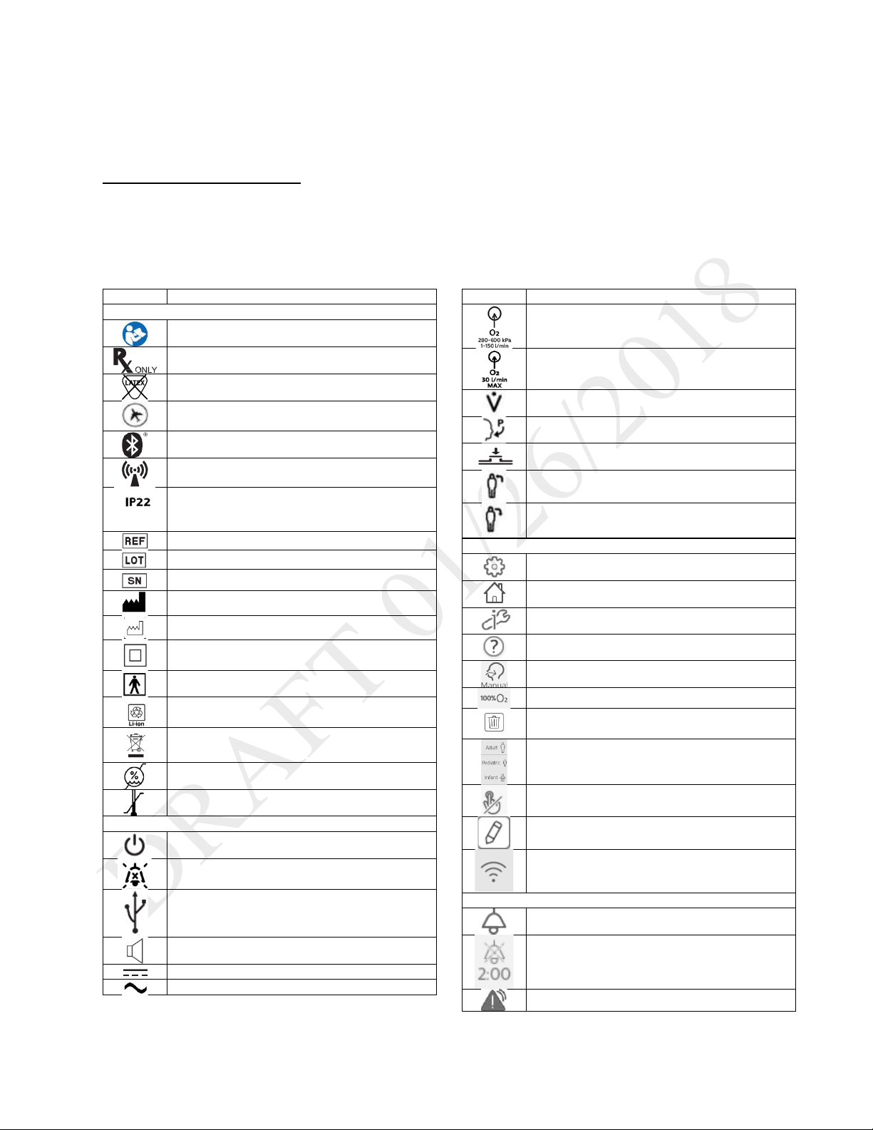
Symbol
Definition
Symbols on the Model and Warning Label
Refer to instruction manual
Prescription device
Not made with natural rubber latex
For airline use. Complies with RTCA D0160
section 21, category M
Bluetooth symbol
This equipment includes RF transmitters.
IP22: protection against finger-sized objects
tilted up to 15 degrees.
Catalog number
Batch code
Serial number
Manufacturer
Date of manufacture
Class II equipment
BF applied part
LI-ion recycling
Waste electrical & electronic equipment
Humidity limit
Temperature limit
Symbols on the Device
On/Off (Standby) button
Alarm Silence button
USB connection
Nurse call connection
DC power (direct current)
AC power (alternating current)
Symbol
Definition
Oxygen inlet
Low flow oxygen inlet
Flow sensor cable connection
Proximal pressure out
AEV control line
Patient in
Patient out
Symbols on the Screen - General
Prescription settings
Home screen
Options
Help
Manual breath
Deliver 100% oxygen
Delete prescription
Patient type indicators
Touch screen lock
Edit
Wi-Fi
Symbols on the Screen - Alarms
Alarms tab
Alarm Silence
High priority alarm
Symbols Glossary
This glossary contains the symbols on the model label and on the device exterior. Software symbol explanations appear
throughout this book. For a complete explanation of symbols appearing on the device and associated labels, go to the
following web address:
http://www.symbols.philips.com
and protected against dripping water when
Symbols Glossary 9
Page 10

Instructions for Use | Introduction
Medium or low priority alarm
System message
Alarm reset
Symbols on the Screen – Monitoring Views
See chapter 2, “About Trilogy Evo.”
Symbols on the Screen - Power
See the Power Management chapter.
Symbols on the Screen –Connectivity
Bluetooth enabled
Bluetooth connected
USB is exporting data
Symbols Glossary 10
Page 11

Instructions for Use | Introduction
How to Contact Philips Respironics
If you need help setting up, using or maintaining Trilogy Evo Universal, or if this device does not perform as expected, contact Philips Respironics.
Call Philips Respironics Customer Service at:
• 1-724-387-4000
• 1-800-345-6443 (toll-free)
• +49 8152 93060 (international)
How to Contact Philips Respironics 11
Page 12

Instructions for Use | About Trilogy Evo Universal
1. On/off (standby) button
1. Carrying handle
2. About Trilogy Evo Universal
Parts of Trilogy Evo Universal
Front Panel
2. AC power indicator
3. Alarm indicator/alarm silence
4. Alarm bar
5. Touch screen
6. Ambient light sensor
Back Panel
Parts of Trilogy Evo Universal 12
2. FiO
3. Power cord retention clip
4. Air inlet
5. Oxygen blender
6. High pressure oxygen inlet
7. Air vents
sensor access panel
2
Page 13

Instructions for Use | About Trilogy Evo Universal
1. Accessory USB port
1. AC power connector
Patient Panel
(pulse oximeter, CO2 monitor)
2. Inspiratory port (to patient)
3. Proximal pressure port
4. Active exhalation valve line connection for
ActivePAP and Active Flow circuits
5. Dual limb active exhalation valve connection (from
patient)
6. Flow sensor cable connector
Utility Panel
2. Air vents
3. Low flow oxygen inlet
4. Detachable battery access door
5. Micro USB Port for device service
6. Accessory USB Port (USB external storage
device, communication cables)
7. Remote alarm or nurse call connector (RJ9)
8. DC power connector
Parts of Trilogy Evo Universal 13
Page 14

Instructions for Use | About Trilogy Evo Universal
Parts of the User Interface
Standard Screen Elements
1. Menu bar
2. Main window
3. Monitored parameters pane
4. Status bar
Menu Bar
Use the menu bar to navigate, manage alarms, and see the active prescription at a glance.
1. Home: view the main window
2. Prescriptions: manage patient prescriptions
3. Options:
- Device Settings
- Calibration
- Data Transfer
- Information
- Alarm & Event Log
4. Patient type indicator
Parts of the User Interface 14
Page 15

Instructions for Use | About Trilogy Evo Universal
1
Manual breath
8
Wi-Fi
2
Deliver 100% Oxygen
9
Alarm silence
3
100% Oxygen timer
10
Power sources and their status
4
CMD
11
5
USB data transfer
12 6 Bluetooth
13
Device Actions Menu
7
Bluetooth data transfer
14
System time
Main Window
The main window contents vary depending on the action you are performing. The main window can show the standby window, prescription
window, monitoring window, and others.
Monitored Parameters Pane
Use the monitored parameters pane to see measured and calculated
values while delivering therapy. These values vary based on the circuit,
therapy mode, and accessory type.
Depending on the accessories you use, values such as SpO2 appear
during active ventilation and during standby.
Parameters that may appear are:
- PIP: peak inspiratory pressure
- Vte: exhaled tidal volume
- RR: respiratory rate
- MinVent: minute ventilation
- SpO
- Pulse Rate
- etCO
: saturation of peripheral oxygen
2
: end tidal carbon dioxide
2
Status Bar
Use the status bar to monitor device status and the availability of manual therapeutic actions.
Monitoring Window
During ventilation, a monitoring window, or home screen, contains information such as measured parameters and battery status. You can select
the type of information you want to see.
Selecting a Monitoring View
To select a monitoring view during ventilation:
1. In the Menu Bar, tap the Home button.
2. In the monitoring window, tap the Views button
3. In the Views menu, tap the type of view you want to use.
Monitoring Window 15
Page 16

Instructions for Use | About Trilogy Evo Universal
Views menu icon
Monitoring window contents
- Manometer pressure indicator
- Set parameters
Modes.”
Large manometer
- Large manometer pressure indicator
- Customizable scalar waveform graphs
Button
Description
Select the waveforms to graph. On
graphs.
Pause graphing.
Automatically size the vertical scale
Tap to change the time scale, and
the list.
Types of monitoring windows
Monitoring windows may vary based on your model.
- Set parameters
Small manometer
Measured and
calculated
parameters
Waveform graphs
- Measured and calculated parameters
- Additional parameters based on the prescription (including
accessories)
- This is the default view.
An explanation of dynamic parameters is in chapter 3, “Therapy
- Six measured and calculated parameters
To customize the graphs, use the buttons in the window as follows:
the Select Waveforms dialog box,
select data for the top and bottom
to fit the data.
then select a new time scale from
Monitoring Window 16
Page 17

Instructions for Use | Therapy Modes and Controls
3. Therapy Modes and Controls
Overview
Trilogy Evo Universal therapy modes can be used for invasive and noninvasive ventilation with all circuit types, including mouthpiece ventilation.
Breath Types
Trilogy Evo Universal can deliver the following breath types:
o Mandatory: Ventilator-initiated, time-cycled
o Assist-Control: Patient-initiated, time-cycled
o Spontaneous: Patient-initiated, patient-cycled
Triggering and Cycling
Patient triggers
Auto-Trak is a flow trigger with rules that make patient-triggering and cycling more comfortable for the patient. The system uses multiple
algorithms to detect the start and end of the breath. Also, it automatically adjusts the trigger and cycle sensitivity to optimize synchronization
between the patient and the ventilator.
Sensitive Auto-Trak is a more sensitive version of Auto-Trak
Flow trigger initiates a breath when the patient’s inspiratory effort creates a flow equal to or greater than the flow trigger sensitivity setting. A
lower number is more sensitive. As inspiratory flow begins to decrease, the device cycles to expiration when the patient flow is less than the
percentage of peak flow, based on the flow-cycle sensitivity setting.
Ventilator trigger
Time Trigger is time-based, defined by the Breath Rate setting.
Flow patterns
Ramp wave pattern: airflow starts high and decreases throughout inspiration of the breath.
Square wave pattern: airflow is generally constant throughout inspiration of the breath.
Therapy Modes Overview
Control Modes: breaths are assist-control or mandatory.
• A/C-PC: Assist control – assist-control and mandatory breaths with pressure control
• A/C-VC: Assist control – assist control and mandatory breaths with volume control
Spontaneous modes: the patient initiates all breaths.
• CPAP: Continuous positive airway pressure
• PSV: Pressure support ventilation
Overview 17
Page 18

Instructions for Use | Therapy Modes and Controls
Mode
Breath Types
Trigger Source
Inspiration
Cycle
Exhalation
Control Modes
Assist-Control
Patient
Assist-Control
Patient
Spontaneous Modes
CPAP
Spontaneous
Patient
CPAP
Patient
CPAP
Mixed Modes
Spontaneous
Patient
Patient
Pressure Support + PEEP
Assist-Control
Patient
Pressure Support + PEEP
Assist-Control
Patient
Mixed modes: breaths are spontaneous, assist-control, or mandatory.
• S/T: Spontaneous/timed ventilation – spontaneous breaths with pressure support and mandatory breaths with pressure control
• SIMV-PC: Synchronized intermittent mandatory ventilation (pressure control) – spontaneous breaths with pressure support, assist—
control breaths and mandatory breaths with pressure control
• SIMV-VC: Synchronized intermittent mandatory ventilation (volume control) – spontaneous breaths with pressure support, assist—
control breaths and mandatory breaths with volume control
Low Tidal Volume Therapy
For low tidal volume therapy, use the infant/pediatric external flow sensor. See the instructions included with the sensor.
When setting volumes greater than or equal to 50ml, use any circuit type.
When setting volumes greater than or equal to 35ml, use either the active flow or dual limb circuits.
The following pressure modes are available for patients who require a tidal volume less than 35ml:
• A/C-PC
• PSV
• S/T
• SIMV-PC
Therapy Mode Comparison Table
For all modes, the breath type varies based on time of patient inspiration. The breath type is always ventilator-initiated and mandatory when the
Trigger Type is set to Off.
A/C-PC
A/C-VC
PSV Spontaneous Patient Pressure Support + PEEP Patient PEEP
S/T
SIMV-PC
SIMV-VC
Mandatory
Mandatory
Mandatory
Spontaneous Patient
Mandatory
Spontaneous Patient
Mandatory
Ventilator
(Breath Rate)
Ventilator
(Breath Rate)
Ventilator
(Breath Rate)
Ventilator
(Breath Rate)
Ventilator
(Breath Rate)
Pressure Control +PEEP Inspiratory
Tidal Volume
IPAP
Pressure Control + PEEP Inspiratory
Tidal Volume
Time
Inspiratory
Time
Inspiratory
Time
Patient PEEP
Time
Patient PEEP
Inspiratory
Time
PEEP
PEEP
EPAP
PEEP
PEEP
Overview 18
Page 19

Instructions for Use | Therapy Modes and Controls
Setting Name
Description
Pressure Control
Inspiratory pressure above PEEP
PEEP
Positive end expiratory pressure
Rise Time
Time required for the ventilator to change from the expiratory pressure setting to the inspiratory
pressure setting when the breath is triggered.
Breath Rate
Minimum rate of breaths per minute
Inspiratory Time
Length of the inspiratory phase
Trigger Type
• Auto-Trak (passive circuits only)
• Off
Flow Trigger
Sensitivity
This control is available when the trigger type is Flow Trigger. The flow trigger initiates when the
patient’s inspiratory effort creates a flow equal to or greater than the flow trigger sensitivity setting.
Flow Cycle
This control is available when the trigger type is Flow Trigger.
device cycles to expiration.
FiO2
(optional)
Requires model with oxygen blender
Control Modes
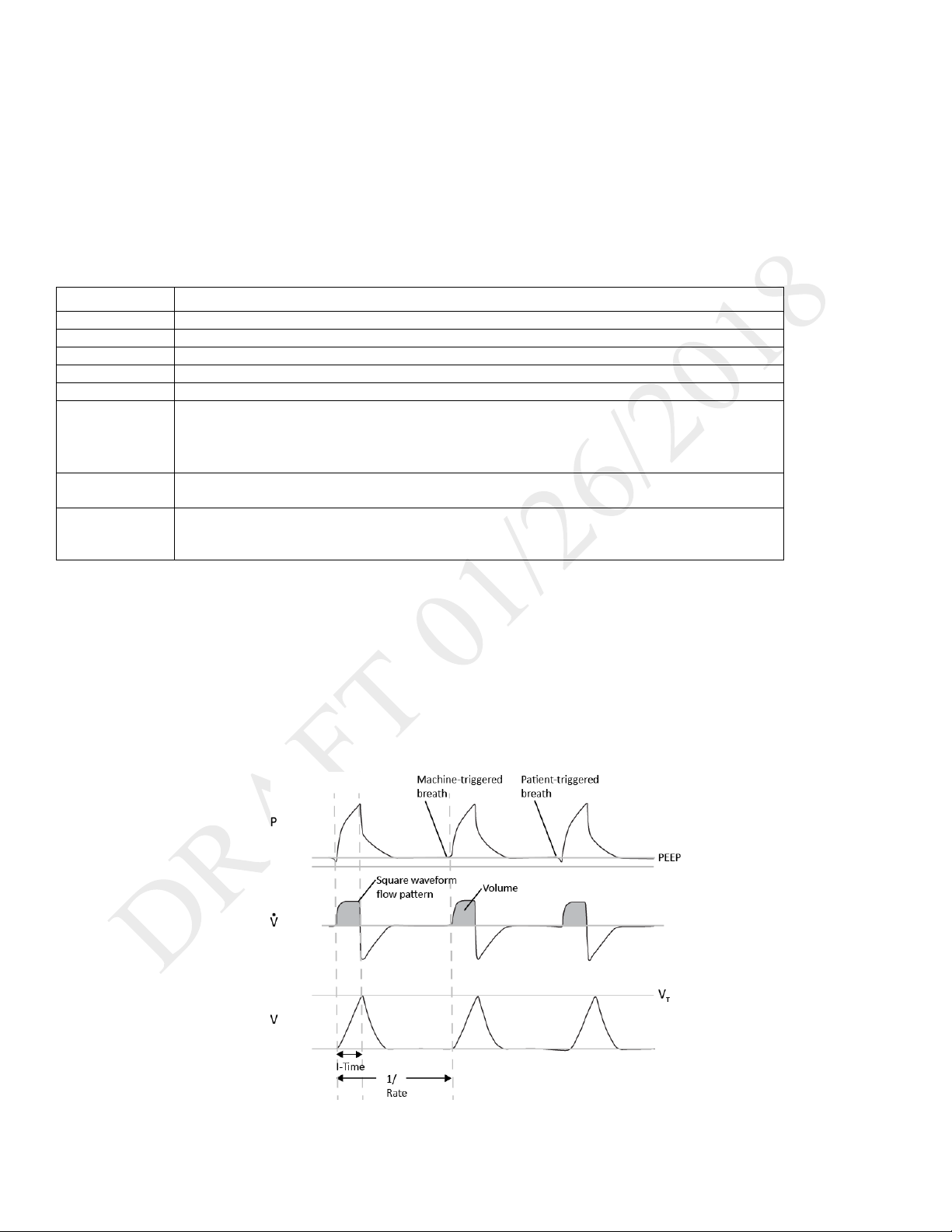
A/C-PC: Assisted/Control-Pressure Control
DESCRIPTION:
The A/C-PC mode provides pressure-controlled mandatory or assist-control breaths. When the Trigger Type is set to Off, the ventilator triggers and
cycles all breaths. When the Trigger Type is not set to Off, then the ventilator or the patient can trigger a breath, and the ventilator cycles all
breaths.
SETTINGS:
• Sensitive Auto-Trak (passive circuits only)
• Flow Trigger (Passive, Active PAP, Active Flow, or Dual Limb circuits)
Sensitivity
SETTABLE ALARMS:
• Circuit disconnect
• High tidal volume
• Low tidal volume
• High minute ventilation
• Low minute ventilation
• High respiratory rate
• Low respiratory rate
ILLUSTRATION
As flow begins to decrease during inspiration, if the patient flow is less than the flow cycle set point, the
1. EPAP
2. Pressure control
Control Modes 19
Page 20
Instructions for Use | Therapy Modes and Controls
Setting Name
Description
Tidal Volume
Set inspiratory volume
PEEP
Positive end expiratory pressure
Inspiratory Time
Length of the inspiratory phase
Breath Rate
Minimum rate of mandatory breaths per minute
Flow Pattern
Sets the shape of the waveform as a ramp or square
Trigger Type
• Auto-Trak
• Off
Flow Trigger
Sensitivity
This control is available when the trigger type is Flow Trigger. The flow trigger initiates when the
patient’s inspiratory effort creates a flow equal to or greater than the flow trigger sensitivity setting.
Flow Cycle
This control is available when the trigger type is Flow Trigger.
device cycles to expiration.
A/C-VC: Assisted/Control-Volume Control
DESCRIPTION:
The A/C-VC mode provides volume-controlled mandatory and assist breaths. When the Trigger Type is set to Off, both triggering and cycling are
performed by the ventilator. When the Trigger Type is not Off, then the trigger can be performed by the vent or patient and the cycle is always
performed by the ventilator. To deliver the set volume in the set time, the ventilator alters the flow rate. The flow pattern setting defines the shape
of the flow delivery pattern.
SETTINGS:
• Sensitive Auto-Trak (passive circuits only)
• Flow Trigger (Passive, Active PAP, Active Flow, or Dual Limb circuits)
Sensitivity
SETTABLE ALARMS:
• Circuit disconnected
• High tidal volume
• Low tidal volume
• High minute ventilation
• Low minute ventilation
• High respiratory rate
• Low respiratory rate
• High inspiratory pressure
• Low inspiratory pressure
ILLUSTRATION
As flow begins to decrease during inspiration, if the patient flow is less than the flow cycle set point, the
Control Modes 20
Page 21
Instructions for Use | Therapy Modes and Controls
Setting Name
Description
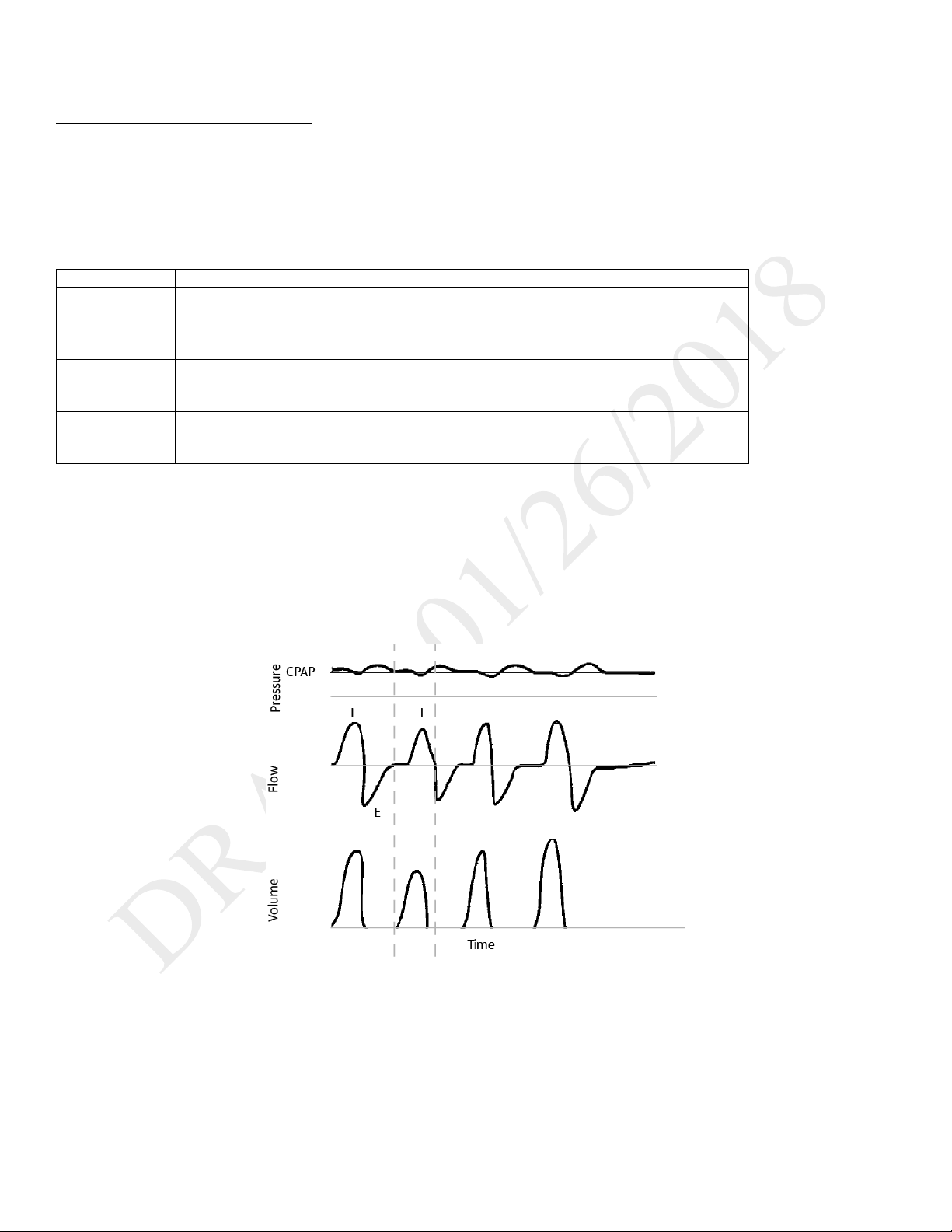
CPAP
Continuous positive airway pressure range
Trigger Type
•
Flow Trigger (Passive, Active PAP, Active Flow, or Dual Limb circuits)
Flow Trigger
This control is available when the trigger type is Flow Trigger. The flow trigger initiates when the
setting.
Flow Cycle
This control is available when the trigger type is Flow Trigger.
point, the device cycles to expiration.
Spontaneous Modes
CPAP: Continuous Positive Airway Pressure
DESCRIPTION:
In CPAP mode, the pressure delivered to the patient during both inhalation and exhalation is the CPAP pressure setting. All breaths in this mode are
spontaneous breaths. The ventilator monitors inspiratory and expiratory tidal volume.
SETTINGS:
Auto-Trak
• Sensitive Auto-Trak (passive circuits only)
•
Sensitivity
Sensitivity
SETTABLE ALARMS:
• Circuit disconnected
• High tidal volume
• Low tidal volume
• High minute ventilation
• Low minute ventilation
• High respiratory rate
• Low respiratory rate
ILLUSTRATION
patient’s inspiratory effort creates a flow equal to or greater than the flow trigger sensitivity
As flow begins to decrease during inspiration, if the patient flow is less than the flow cycle set
Spontaneous Modes 21
Page 22
Instructions for Use | Therapy Modes and Controls
Setting Name
Description
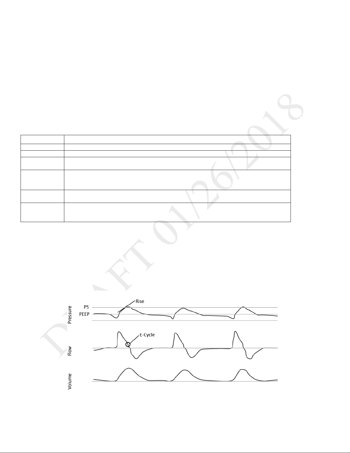
Pressure Support
Target pressure that the device delivers during the inspiratory phase of a spontaneous breath
PEEP
Positive end expiratory pressure
Rise Time
Time required for the ventilator to change from the expiratory pressure setting to the inspiratory
pressure setting when the breath is triggered.
Trigger Type
• Auto-Trak
Flow Trigger (Passive, Active PAP, Active Flow, or Dual Limb circuits)
Flow Trigger
Sensitivity
This control is available when the trigger type is Flow Trigger. The flow trigger initiates when the
patient’s inspiratory effort creates a flow equal to or greater than the flow trigger sensitivity setting.
Flow Cycle
This control is available when the trigger type is Flow Trigger
device cycles to expiration.
PSV: Pressure Support Ventilation
DESCRIPTION:
PSV mode is patient-triggered, pressure-limited, and flow-cycled. With this strategy, breaths are assisted by a set inspiratory pressure that is
delivered until inspiratory flow drops below a set threshold.
In the PSV mode, the ventilator delivers spontaneous, pressure-supported, breaths and user-initiated mandatory breaths. The ventilator functions
as a demand flow system, with the patient triggering breaths and determining their timing and volume. The ventilator can support the breaths with
the set pressure support.
The Pressure Control setting defines the applied pressure above PEEP. The patient determines the breath timing. As in other dual limb modes, you
also set PEEP, inspiratory trigger, and O2. It is recommended that you set backup ventilation in PSV mode.
SETTINGS:
• Sensitive Auto-Trak (passive circuits only)
•
Sensitivity
SETTABLE ALARMS:
• Circuit disconnected
• High tidal volume
• Low tidal volume
• High minute ventilation
• Low minute ventilation
• High respiratory rate
• Low respiratory rate
ILLUSTRATION:
As flow begins to decrease during inspiration, if the patient flow is less than the flow cycle set point, the
Spontaneous Modes 22
Page 23

Instructions for Use | Therapy Modes and Controls
Setting Name
Description
IPAP
Inspiratory positive airway pressure
Must be greater than or equal to EPAP
EPAP
Expiratory positive airway pressure
Rise Time
Time required for the ventilator to change from the expiratory pressure setting to the inspiratory pressure
setting when the breath is triggered.
Breath Rate
Minimum rate of breaths per minute. If the patient doesn’t trigger a breath within this time, the ventilator
triggers the breath.
Inspiratory Time
For a mandatory breath, length of the inspiratory phase
Trigger Type
• Auto-Trak
• Flow Trigger (Passive, Active PAP, Active Flow, or Dual Limb circuits)
Flow Trigger
Sensitivity
This control is available when the trigger type is Flow Trigger. The flow trigger initiates when the patient’s
inspiratory effort creates a flow equal to or greater than the flow trigger sensitivity setting.
Flow Cycle
This control is available when the trigger type is Flow Trigger
device cycles to expiration.
Mixed Modes
S/T: Spontaneous/Timed
DESCRIPTION:
A bi-level therapy mode where each breath is patient-triggered and patient-cycled or ventilator-triggered and ventilator-cycled. In this mode, an
IPAP is delivered during inhalation and a lower EPAP is delivered during exhalation. The duration of a spontaneous breath is determined by the
patient effort. The duration of a mandatory breath is determined by the inspiratory time setting. Remember that the IPAP setting is the maximum
pressure the ventilator will deliver; it is not in addition to the EPAP setting.
SETTINGS:
• Sensitive Auto-Trak (passive circuits only)
Sensitivity
As flow begins to decrease during inspiration, if the patient flow is less than the flow cycle set point, the
SETTABLE ALARMS:
• Circuit disconnect
• High tidal volume
• Low tidal volume
• High minute ventilation
• Low minute ventilation
• High respiratory rate
• Low respiratory rate
ILLUSTRATION:
Mixed Modes 23
Page 24

Instructions for Use | Therapy Modes and Controls
Setting Name
Description
Pressure Control
Defines the applied pressure for all breaths
Pressure Support
Target pressure that the device delivers during the inspiratory phase of a spontaneous breath
PEEP
Positive end expiratory pressure
pressure setting.
Inspiratory Time
For a mandatory breath, length of the inspiratory phase
Rise Time
Time required for the ventilator to change from the expiratory pressure setting to the inspiratory pressure
setting when the breath is triggered.
Breath Rate
Minimum rate of mandatory breaths per minute
Trigger Type
• Auto-Trak
• Flow Trigger (Passive, Active PAP, Active Flow, or Dual Limb circuits)
Flow Trigger
Sensitivity
This control is available when the trigger type is Flow Trigger. The flow trigger initiates when the patient’s
inspiratory effort creates a flow equal to or greater than the flow trigger sensitivity setting.
Flow Cycle
This control is available when the trigger type is Flow Trigger
device cycles to expiration.
SIMV-PC: Synchronous Intermittent Mandatory Ventilation- Pressure Control
DESCRIPTION:
SIMV-PC mode is a pressure control mode that provides a mixture of mandatory and spontaneous breaths. SIMV-PC mode guarantees one
mandatory breath in each cycle. Spontaneous breaths can be delivered with pressure support. The breath rate determines the length of the cycle.
The first phase of the cycle is reserved for synchronizing a mandatory breath with patient effort. If the patient triggers a breath during this phase of
the cycle, the ventilator delivers a synchronized mandatory breath. If a patient does not trigger a breath during the mandatory phase of the cycle,
then the ventilator delivers a mandatory breath. Breaths triggered by the patient after the mandatory breath in the cycle are spontaneous breaths.
This process is repeated at the start of every cycle.
SETTINGS:
Sensitivity
SETTABLE ALARMS:
• Circuit disconnect
• High tidal volume
• Low tidal volume
• High minute ventilation
• Low minute ventilation
• High respiratory rate
• Low respiratory rate
ILLUSTRATION
Positive pressure maintained in the patient circuit during exhalation: must be less than or equal to the
• Sensitive Auto-Trak (passive circuits only)
As flow begins to decrease during inspiration, if the patient flow is less than the flow cycle set point, the
Mixed Modes 24
Page 25

Instructions for Use | Therapy Modes and Controls
Setting Name
Description
Tidal Volume
Target gas volume that the device delivers during a spontaneous breath
Pressure Support
Target pressure that the device delivers during the inspiratory phase of a spontaneous breath
PEEP
Positive end expiratory pressure
pressure setting.
Inspiratory Time
For a mandatory breath, length of the inspiratory phase
Rise Time
Time required for the ventilator to change from the expiratory pressure setting to the inspiratory
pressure setting when the breath is triggered.
Breath Rate
Minimum rate of mandatory breaths per minute
Flow Pattern
Sets the flow-pressure waveform
Trigger Type
• Auto-Trak
• Flow Trigger (Passive, Active PAP, Active Flow, or Dual Limb circuits)
Flow Trigger
Sensitivity
This control is available when the trigger type is Flow Trigger. The flow trigger initiates when the
patient’s inspiratory effort creates a flow equal to or greater than the flow trigger sensitivity setting.
Flow Cycle
This control is available when the trigger type is Flow Trigger
device cycles to expiration.
SIMV-VC: Synchronous Intermittent Mandatory Ventilation- Volume Control
DESCRIPTION:
Similar to SIMV-PC, but with volume control.
SETTINGS:
Sensitivity
SETTABLE ALARMS:
• Circuit disconnect
• High tidal volume
• Low tidal volume
• High minute ventilation
• Low minute ventilation
• High respiratory rate
• Low respiratory rate
• High inspiratory pressure
• Low inspiratory pressure
ILLUSTRATION
See SIMV-PC.
Positive pressure maintained in the patient circuit during exhalation: must be less than or equal to the
• Sensitive Auto-Trak (passive circuits only)
As flow begins to decrease during inspiration, if the patient flow is less than the flow cycle set point, the
Therapy Features
The following features are available in addition to the therapy modes.
Backup Ventilation Enable
DESCRIPTION
Set the device to deliver ventilator-initiated breaths when patient-initiated breaths are not detected, based on the Apnea alarm interval. When you
turn Backup Ventilation on, set an Apnea interval in the alarm settings tab. Within the apnea interval; if no breaths are triggered by the patient, the
ventilator delivers breaths at the set pressure or volume based on the Backup Rate. When an Apnea alarm occurs, the ventilator automatically
starts backup ventilation. When two consecutive patient-initiated breaths are detected, the ventilator automatically reverts to patient-initiated
breaths.
Backup ventilation settings take precedence over standard therapy mode settings.
Therapy Features 25
Page 26

Instructions for Use | Therapy Modes and Controls
SETTINGS:
• Backup Ventilation (On/Off): when you turn this setting On, set an Apnea interval in the alarm settings tab.
• Backup Rate: when in backup ventilation, the backup breath rate takes precedence over any breath rate set in the therapy mode. The rate cannot be less
than the Breath Rate set in the current therapy mode.
• Backup Inspiration Time (CPAP and PSV modes only) when in backup ventilation the Back Up Tinsp controls the duration of inspiration.
• Backup PS (CPAP mode only)
• Backup Rise Time (CPAP mode only)
To access the Backup Ventilation feature, in the Prescription window, tap Advanced. When you turn the feature on, the additional settings appear
in the prescription window.
If Trigger Type is Off, this feature is unavailable.
APPLICABLE THERAPY MODES
• A/C-PC
• A/C-VC
• CPAP
• PSV
• S/T
• SIMV-PC
• SIMV-VC
Insp Time Min/Max Enable
DESCRIPTION
Set the minimum and maximum inspiratory time for pressure support breath types. This feature changes inspiration time from a constant to a
variable value so you can select a range for the inspiration time.
The range allows the patient to have a chance to cycle. When the maximum time has passed with no patient-initiated breath, then the ventilator
automatically cycles the breath.
To access this feature, in the Prescription window, tap Advanced. When you turn the feature on, the additional settings appear in the prescription
window.
APPLICABLE THERAPY MODES
• PSV
• S/T
• SIMV-PC
• SIMV-VC
Sigh Enable
DESCRIPTION
Delivers a periodic, larger volume breath.
SETTINGS:
• Sigh (On/Off)
• Sigh Volume
• Sigh Frequency (deliver a sigh after X number of patient- or ventilator- triggered breaths)
To access the Sigh feature, in the Prescription window, tap Advanced. When you turn the feature on, the additional settings appear in the
prescription window.
APPLICABLE THERAPY MODE
• A/C-VC
Therapy Features 26
Page 27

Instructions for Use | Therapy Modes and Controls
To start an oxygen flush:
To deliver a manual breath:
Setting Name
Setting Range/Increment
Adult patient type:
• Increments: 1 cmH
2
O
Pediatric patient type:
• Increments: 1 cmH
2
O
Infant patient type:
Therapy Actions
Oxygen Flush
DESCRIPTION
This feature requires the oxygen blender. When active, the device delivers 100% oxygen for two minutes. This feature functions independent of
any oxygen blending setting. During an oxygen flush, the High FiO2 alarm is disabled.
WORKING WITH OXYGEN FLUSH
Tap 100% O2 in the status bar and then tap Start. A timer appears that counts down
the two minutes.
To stop an oxygen flush:
Tap 100% O2 in the status bar and then tap Stop.
APPLICABLE THERAPY MODES
All
Manual Breath
DESCRIPTION
Delivers a breath based on the current therapy mode settings.
Tap the Manual Breath button in the status bar and then tap Start.
APPLICABLE THERAPY MODES
• A/C-PC
• A/C-VC
• PSV
• S/T
• SIMV-PC
• SIMV-VC
Therapy Control Settings
Therapy control settings can be interdependent. For guidance, see the previous therapy mode descriptions.
Backup Pressure
Support
Therapy Control Settings 27
• All circuits but passive: 0-60 cmH
• Passive circuit: 0-57 cmH
• All circuits: 0-30 cmH
O
2
O
2
O
2
Page 28

Instructions for Use | Therapy Modes and Controls
Setting Name
Setting Range/Increment
• All circuits: 0-20 cmH
O
• Increments: 1 cmH
2
O
Adult patient type: 0-80 BPM, 1BPM increments
Infant patient type: 0-40 BPM, 1 BPM increments
Adult and pediatric patient types: 3-25 cmH2O, 1 cm H2O increments
Infant patient type: 3-15 cmH2O, 1 cm H2O increments
Adult and pediatric patient types: 3-25 cmH2O, 1 cm H2O increments
Infant patient type: 3-15 cmH2O, 1 cm H2O increments
21-100%, 1% increments
(21% = ambient condition, no control)
Flow Cycle Sensitivity
10-90%, 1% increments
Square: airflow is constant
Ramp: inspiration airflow starts high and decreases
Flow Trigger Sensitivity
0.5 (high sensitivity) to 9 L/min (low sensitivity)
Adult patient type: 0.5-5.0 seconds, 0.1 second increments
Pediatric patient type: 0.3-2.0 seconds, 0.1 second increments
Infant patient type: 0.3-1.0 seconds, 0.1 second increments
Adult patient type: 3-60 cmH2O, 1 cmH2O increments
Pediatric patient type: 3-45 cmH2O, 1 cmH2O increments
Infant patient type: 3-35 cmH2O, 1 cmH2O increments
Max Pressure
• 6-60 cmH
2
O, 1 cmH2O increments
Adult patient type:
Increments: 1 cmH
2
O
Pediatric patient type:
• Increments: 1 cmH
2
O
Infant patient type:
• Increments: 1 cmH
2
O
Adult patient type:
• Increments: 1 cmH
2
O
Pediatric patient type:
Increments: 1 cmH
O
Infant patient type:
Increments: 1 cmH
O
Adult patient type:
Increments: 1 cmH
2
O
Pediatric patient type:
Increments: 1 cmH
2
O
Infant patient type:
Increments: 1 cmH
2
O
• All circuits but passive: 0-60 cmH
O
• Increments: 1 cmH
2
O
Rise Time
0 (faster) to 6 (slower)
Adult patient type:
Increment: 5 ml
2
Breath Rate
CPAP
EPAP Min/Max
FiO2
Flow Pattern
Inspiratory Time
IPAP
PEEP
Pediatric patient type: 0-60 BPM, 1BPM increments
• Active circuit: 0-35 cmH
• Passive circuit: 3-25 cmH
O
2
O
2
•
• Active circuit: 0-25 cmH
• Passive circuit: 3-25 cmH
O
2
O
2
Pressure Control
Pressure Support
PS Min/Max
• Active circuit: 0-15 cmH
• Passive circuit: 3-15 cmH
O
2
O
2
• All circuits but passive: 0-60 cmH
• Passive circuit: 0-57 cmH
• All circuits: 0-30 cmH
•
• All circuits: 0-20 cmH
•
O
2
O
2
2
O
2
2
• All circuits but passive: 0-60 cmH
• Passive circuit: 0-57 cmH
O
2
•
• All circuits: 0-30 cmH
O
2
•
• All circuits: 0-20 cmH
O
2
•
• Passive circuit: 0-57 cmH
O
2
O
2
O
2
2
Tidal Volume
70-1200 ml
Therapy Control Settings 28
Page 29

Instructions for Use | Therapy Modes and Controls
Setting Name
Setting Range/Increment
• Auto-Trak (passive circuits only)
• Off
Pediatric patient type:
Dual limb or active flow: 35-400 ml
Passive or Active PAP: 50-400 ml
Increment: 5 ml
Trigger Type
• Sensitive Auto-Trak (passive circuits only)
• Flow Trigger (all circuits)
Dynamic Therapy Parameters
It is unnecessary to perform an inspiratory hold to assess the plateau pressure and other lung parameters. The advanced measurement system of
Trilogy Evo estimates lung compliance, airway resistance, AutoPEEP and plateau pressure during normal mechanical ventilation without requiring a
static maneuver.
Dyn R
Airway resistance is the opposition to the motion of gas within the airways. In the Measured and Calculated Parameters window, this value is Dyn R
(dynamic resistance), so named because it is estimated without requiring a static maneuver.
At the end of inhalation, Trilogy Evo estimates the airway resistance by computing the ratio between the driving pressure from within the lung to
the air flow. The flow term is corrected to take into account the contributions of the following:
• Intrinsic PEEP, by subtracting the expiratory flow at the end of exhalation
• The elastic recoil of the lungs, by adding the tidal volume divided by the respiratory time constant, τ.
(Respiratory time constant is the airway resistance times the summed compliance of the lung and chest wall)
Trilogy Evo calculates Dyn R using the following formula:
=
Where:
• PIP is the peak inspiratory pressure (pressure at the end of inhalation)
•
•
•
•
is the extrinsic pressure (pressure applied by the ventilator) at the end of the breath
is the tidal volume
(
= ) is the patient flow at the end of the exhalation (EOE)
(
= ) is the patient flow at the end of inhalation(EOI)
To understand the calculations adopted to compute Dyn R, note that the above equation can be rewritten as the classic equation for airway
resistance:
−( + + / )= ∗
That is to say, pressure across the resistance equal to resistance times flow, where:
•
• +
= − ∗ () this value is the intrinsic PEEP or AutoPEEP (see the section, “AutoPEEP” below)
is the total pressure (extrinsic plus intrinsic) at the end of the breath
−
(
= )−
(
= )+
()
Dyn C
Lung Compliance is the ratio between the tidal volume and the changes in pressure. In the Measured and Calculated Parameters window, this
value is Dyn C (dynamic compliance), so named because it is estimated without requiring a static maneuver.
Trilogy Evo estimates the integrated compliance of the pulmonary system, (the summed compliance of the lung and chest wall). The compliance of
the respiratory system can be derived from the measurement of plateau pressure,
the difference between the
Trilogy Evo calculates Dyn C using the following formula:
Dynamic Therapy Parameters 29
and PEEP.
, using the relationship between the tidal volume, , and
Page 30

Instructions for Use | Therapy Modes and Controls
=
−
Where:
• PEEP is the total pressure (intrinsic plus extrinsic) at the start of the breath ( =
is the tidal volume
•
+ )
Note that the compliance is related to the airway resistance by the respiratory time constant, τ, by the relationship described above.
=
Dyn Pplat
Plateau pressure is the pressure applied to small airways and alveoli during positive-pressure mechanical ventilation. In the Measured and
Calculated Parameters window, this value is Dyn Pplat. Having already estimated the compliance (Dyn R and Dyn C above), Trilogy Evo calculates
Dyn Pplat as follows:
=
+ +
Where:
•
is the tidal volume
• is dynamic compliance
• PEEP is the total pressure (intrinsic plus extrinsic) at the start of the breath ( =
•
= − ∗ () this value is the intrinsic PEEP or AutoPEEP
+
AutoPEEP
Intrinsic PEEP, , is the resistive pressure at the end of exhalation (EOE), that occurs when a new breath is initiated before the previous breath
is completed. In the Measured and Calculated Parameters window, this value is AutoPEEP. AutoPEEP can be used as a guide to detect the presence
of dynamic hyperinflation. In most cases, this number represents the pressure in the small airways at the start of the breath in excess of the PEEP
applied by the ventilator. In some cases, such as a ventilated, complex, COPD patient, the displayed pressure may not be accurate. However, in
these complex cases, any non-zero pressure displayed (accurate or not) indicates the presence of AutoPEEP. When Auto PEEP is zero, this
indicates that there is no intrinsic PEEP.
Trilogy Evo calculates AutoPEEP using the following formula:
(
= )
Where:
• Dyn R is the dynamic resistance (explained in a previous section, “Dyn R” above)
•
= − ∗
(
= ) is the patient flow at the end of the exhalation (EOE)
Dynamic Therapy Parameters 30
Page 31

Instructions for Use | Device Setup
Step
Section
Page
1. Place the device.
Placement
31
2. Connect AC power.
Connecting AC Power
31
3. Install filters.
Installing Filters
32
4. Connect a circuit.
Connecting a Circuit
32
5. Add oxygen (optional).
Adding Oxygen
35
6. Start the device.
Starting Trilogy Evo Universal
36
4. Device Setup
Setup Overview
To set up Trilogy Evo, follow the steps shown below. See the accompanying section for instructions.
Placement
Place Trilogy Evo on a stable, flat, hard surface. Air must flow freely. Do not block the air vents with items such as bedding or curtains. Do not place
Trilogy Evo near any heating or cooling equipment or air supplies such as forced air vents, radiators, or air conditioners. Ensure the USB and
detachable battery panel doors remain closed when not in use.
If the device has been stored outside the normal operating temperature stated in “Technical Specifications,” ensure the device reaches operating
temperature before connecting power.
See the “EMC Information” chapter for guidance on possible electromagnetic interference.
Connecting AC Power
Use the AC cord provided to connect AC power before pressing the power button. Verify Trilogy Evo Universal is using AC power, indicated by the
green LED light next to the power button.
To use other power sources, such as the detachable battery or an external battery, see the “Power Management” chapter.
Installing Filters
CBRN Filter
To install the CBRN filter:
1. Ensure the CBRN filter adapter gasket is securely seated.
2. Place the filter adapter onto the bayonet mount and twist clockwise to lock in place.
3. Screw the CBRN filter onto the filter adapter.
Installing Filters 31
Page 32

Instructions for Use | Device Setup
Air-Inlet Foam Filter
Ensure the air-inlet foam filter is installed correctly.
To install the air-inlet foam filter, pinch the filter as you press it into the filter cover as shown. Position it securely behind the top and bottom
restraints.
Particulate Filter
To install a particulate filter:
1. 2. 3. 4.
1. Twist the filter cover counterclockwise and pull out to remove it.
2. Place the filter over the bayonet mount.
3. Twist clockwise a quarter of a turn.
4. Replace the filter cover and turn clockwise to secure.
Installing Filters 32
Page 33

Instructions for Use | Device Setup
1
Bacteria filter
2
Tubing
3
Exhalation port
Connecting a Circuit
Be certain that any breathing system filter used with this device complies with ISO 23328-1 and ISO 23328-2. · To prevent patient or ventilator
contamination, we recommend you use a Respironics-approved main flow bacteria filter (Part Number 342077) on the patient gas outlet port.
Filters not approved by Respironics may degrade system performance. Note: A leak device is mandatory during invasive ventilation or when using
a circuit with a non-vented mask.
After you connect the circuit, you may calibrate the circuit. See chapter 7, “Device Options, Calibration.”
For low tidal volumes, see the “Therapy Modes chapter”, section titled “Low Tidal Volume Therapy.”
Passive Single Limb Circuits
1. Connect the bacteria filter (1) on the circuit to the Inspiratory Port.
Connecting a Circuit 33
Page 34

Instructions for Use | Device Setup
1
Bacteria filter
2
Proximal pressure port
3
Active exhalation valve line connection
4
Tubing
1
Bacteria filter
2
Proximal pressure port
3
Active exhalation valve line connection
4
Flow sensor cable connector
5
Tubing
Active PAP Circuits
1. Connect the bacteria filter (1) on the circuit to the Inspiratory Port.
2. Connect the proximal pressure line to the Proximal Pressure Port (2).
3. Connect the active exhalation valve pressure line to the active exhalation valve line connection (3).
Active Flow Circuits
1. Connect the bacteria filter (1) on the circuit to the Inspiratory Port.
2. Connect the proximal pressure line to the Proximal Pressure Port (2).
3. Connect the active exhalation valve pressure line to the active exhalation valve line connection (3).
Connecting a Circuit 34
Page 35

Instructions for Use | Device Setup
1
Bacteria filters
2
Proximal pressure port
3
Active exhalation valve connection
4
Flow sensor cable connector
5
Tubing
6
Flow sensor connected to circuit
4. Connect the flow sensor to the Flow Sensor Cable Connector (4).
Dual Limb Circuits
1. Attach the bacteria filter (1) end of the colored inspiratory tube to the Inspiratory Port.
2. Attach the proximal pressure line (2) to the Proximal Pressure Port.
3. Install the external active exhalation valve (AEV) according to the instructions provided with it (3).
4. Attach the bacteria filter end of the clear expiratory tube to the AEV (3).
5. Attach the flow sensor cable to the flow Sensor Cable Connector (4).
6. Attach the flow sensor to the Y-shaped connector on the circuit (6).
Low Tidal Volume Ventilation
When using volumes between 35 and 50 ml, use the infant/pediatric external flow sensor with either the active flow or dual limb circuits. See the
operating instruction sheets included with those accessories.
Adding Oxygen
High Pressure Oxygen
To ensure accurate oxygen administration and to monitor for the presence of contamination, use an FiO2 sensor or external oxygen monitor to
verify the oxygen concentration in the delivered gas.
To connect high-pressure oxygen: Connect an oxygen hose to the high-pressure oxygen connector on the back panel, and then connect the other
end of the hose to the source. After you have completed the connection, calibrate the O2 sensor. See chapter 7, “Device Options, O2 Sensor
Calibration.” To maintain accuracy, calibrate the oxygen sensor daily.
Adding Oxygen 35
Page 36

Instructions for Use | Device Setup
Low Flow Oxygen
To connect low flow oxygen:
1. Connect the oxygen tubing to the O
2. Connect the O
adapter to the low flow oxygen inlet on the Utility Panel by pressing down on the valve.
2
adapter supplied with the device.
2
Oxygen-Related Alarms
After the oxygen is connected, set the oxygen-related alarms. See chapter 6, “Alarms and System Messages” for instructions.
Oxygen alarms are as follows:
• Oxygen Regulation
• Low SpO
• High SpO
• Low FiO
• High FiO
2
2
2
2
• Low Oxygen Input Pressure
• High Oxygen Input Pressure
Starting Trilogy Evo Universal
To start Trilogy Evo Universal:
1. Visually inspect Trilogy Evo Universal and all accessories, cords, and tubes attached to the device.
2. Verify that circuit connections are secure.
3. Press the On/Off (Standby) button.
4. Listen for a minimum of three beeps as Trilogy Evo Universal performs system start up checks. The beeps test all alarm signals to ensure
proper functioning. Ensure no system messages appear.
5. Watch as the light bar and Alarm Silence button blink once red and once yellow.
6. Confirm that the power sources you have connected are functioning properly and that power is sufficient. For help, see the “Power
Management” chapter.
Starting Trilogy Evo Universal 36
Page 37

Instructions for Use | Device Operation
5. Device Operation
Clinical Assessment
Warning
Before placing a patient on the ventilator, perform a clinical assessment. Considerations should include:
• Choosing alarm settings
• Assessing whether alternative ventilation equipment is required
• Selecting additional accessories, including the patient monitoring accessories you will use
For ventilator-dependent patients, always have alternate ventilation equipment, such as a back-up ventilator or manual resuscitator available.
Ventilator-dependent patients should be continuously monitored by qualified personnel. These personnel should be prepared to provide alternate
therapy in the event of ventilator failure or inoperative equipment.
Entering New Patient Information
To enter new patient information
1. In the Home window, tap the New Patient button. This button clears all existing patient data.
2. In the New Patient window, select a Patient Type:
• Infant
• Pediatric
• Adult
3. Select the Patient Sex.
4. For infant patients, in the Weight section, use the slider or the plus and minus buttons to select the patient’s weight.
For pediatric or adult patients, in the Height section, select the patient’s height.
Note: this information is used to establish default therapy and alarm settings, including tidal volume and alarms based on tidal volume.
5. In the title bar, tap Accept to save your choices.
6. Acknowledge the reminder to ensure a viral/bacterial filter is installed on the outlet of the device.
7. Edit the prescription settings according to the procedure in the next section, “About Prescriptions.” Therapy and alarm settings differ
based on Patient Type. See the “Therapy Modes and Controls” and “Alarms” chapters.
About Prescriptions
System Timeout
When working in the Prescription Settings window, ensure you save your changes. After a period of inactivity, the system reverts to the previous
setting and your changes are not saved. If you are making changes during therapy delivery, the period of inactivity is 30 seconds. If you are making
changes when the system is in standby, the period of inactivity is 5 minutes.
About Prescriptions 37
Page 38

Instructions for Use | Device Operation
Parts of the Prescription Settings Window
7-1: Parts of the Prescription Settings Window
Editing Prescription and Alarm Settings
To edit prescription settings:
1. In the menu bar, tap the prescription settings icon.
2. In the prescription grid, tap Circuit. In the workspace below the grid, select the circuit Type and Size.
3. If you are using a humidifier, in the Active Humidification section, tap Yes. Otherwise, tap No.
4. To save your changes, tap Accept.
5. In the prescription grid, tap Mode. In the workspace below the grid, select the mode.
6. Tap a prescription parameter. In the lower pane, move the slider or use the plus and minus buttons to change the parameter value.
7. Tap the Alarm tab to view and edit the associated alarm settings.
For more information about alarms, including details about each alarm, see “chapter 6: Alarms.”
8. Change the alarm parameters in the lower pane and then click Accept at the top of the window.
9. Continue editing prescription and alarm parameters.
To work with advanced options, tap Advanced.
10. Test the alarms. See “Testing Alarms” in chapter 6.
11. When you are finished, tap Accept to save your changes.
Adding a Prescription
If you want to add another prescription:
1. In the menu bar, tap the prescription settings icon.
2. Tap the Prescription list to expand it and then tap Add New.
3. On the Select Prescription Name dialog box, tap the prescription name that you want to use.
4. Edit the prescription settings as you would for a new prescription.
About Prescriptions 38
Page 39

Instructions for Use | Device Operation
To start ventilation:
In the Prescription Settings window, select the prescription you want to use and then tap Start Therapy.
Deleting a Prescription
To delete a prescription: In the Home window, tap the prescription you want to delete and then tap the trashcan icon.
Starting and Stopping Ventilation
To stop ventilation and put the ventilator on standby:
Press the On/Off (Standby) button on the front panel. On the confirmation window, tap Standby.
To turn the device off:
Press the On/Off (Standby) button on the front panel. On the confirmation window, tap Power Off.
Actions during Ventilation
Using Different Prescriptions
If a clinician has set up more than one prescription; for example, a daytime and nighttime prescription, you can use the prescription list to change
the active prescription.
To select a prescription that uses a circuit type that is different from the current prescription:
1. Press the On/Off (Standby) button on the front panel. On the confirmation window, tap Standby.
2. Attach the circuit type that corresponds to the prescription.
3. On the menu bar, tap the active prescription to expand the prescription list.
4. Tap the prescription you want to use and then confirm your choice.
5. Tap Start Therapy.
To select a prescription that uses a circuit type that is the same as the current prescription:
1. On the menu bar tap the active prescription to expand the prescription list.
2. Tap the prescription you want to use and then confirm your choice.
3. Tap Start Therapy.
Locking and Unlocking the Screen
To lock the screen, expand the Device Actions Menu then tap the Lock Screen button.
Actions during Ventilation 39
Page 40

Instructions for Use | Device Operation
To unlock the screen, tap the screen. On the screen unlock dialog box, tap and hold Yes for three seconds.
When an alarm or system message becomes active, the screen saver is stopped and the automatic screen lock is disabled. For more information,
see the “Alarms” chapter.
Delivering a Manual Breath
To deliver a manual breath, tap the Manual Breath icon in the Status Bar.
Delivering 100% Oxygen
To deliver 100% oxygen for two minutes, tap the 100% O2 icon in the Status Bar.
To stop delivery, tap the icon again and then tap Stop.
Actions during Ventilation 40
Page 41

Instructions for Use | Alarms and System Messages
An increase in circuit resistance can prevent proper operation of some alarms.
Speaking valves, heat moisture exchangers (HMEs), and filters create additional circuit resistance and may affect the performance of
Alarm and Message Indictors
Icon
Description
Light and sound indicators
High alarm
Light bar flashes red
Audible alarm repeats rapidly
Medium alarm
Light bar flashes yellow
6. Alarms and System Messages
Overview
Trilogy Evo Universal generates audible and visual alarms to alert you when conditions require attention.
Warning: To prevent death or serious injury, monitor the patient and the ventilator regularly in order to determine the need to provide emergency
ventilation when an alarm sounds or the ventilator malfunctions. Always test the alarms after changing the circuit or prescription.
alarms chosen for circuit disconnect protection.
Alarm settings are retained when power is lost.
Do not rely on any single alarm to detect a disconnected circuit. Certain components may affect the performance of the alarms chosen
to signal that a circuit is disconnected. Use the apnea, low tidal volume, low minute ventilation, and low respiratory rate alarms in
conjunction with the circuit disconnect alarm. Test these alarms daily and after you change ventilator settings.
About Alarms
When an alarm is active, the following indicators occur:
• An Alarm List appears in the menu bar.
• An Alarm light bar flashes red or yellow, or glows steady yellow, depending on the alarm level (To configure this indicator, see chapter 7,
“Device Options.”
• The Alarm Silence button on the device flashes red or yellow, or glows steady yellow, depending on the alarm level
• An audible alarm sounds.
Trilogy Evo Universal uses three alarm levels:
• High Priority – Requires an immediate response
• Medium Priority – Requires a prompt response
• Low Priority – Requires awareness.
Trilogy Evo Universal also shows system messages to inform you about changing conditions. These messages are described in “Alarms and System
Messages.
When an alarm or system message becomes active, Trilogy Evo Universal stops the screen saver and disables the automatic screen lock.
When external monitors are used, such as an FiO
connection. Alarm settings are stored in the system so if a sensor becomes disconnected, the alarm settings are restored upon reconnection. To
delete external monitor alarm settings, clear all patient data according to the procedure described in the “Device Operation” chapter.
Some patient-related alarms have configurable settings, while others have fixed settings. All system and power alarm settings are fixed. Trilogy Evo
Universal also shows system messages to inform you about changing conditions. Alarm and system message details appear in the “Alarms and
System Messages” section in this chapter.
sensor or SpO2 sensor, associated alarm settings only appear when the ventilator detects sensor
2
About Alarms 41
Audible alarm repeats moderately
Page 42

Instructions for Use | Alarms and System Messages
Alarm and Message Indictors
Icon
Description
Light and sound indicators
Low alarm
Light bar glows steady yellow
Message
Single beep
Resolved alarm
None
Audible alarm repeats slowly
or message
The Alarm List
The Alarm List appears in the menu bar. Tap the list to expand it and view the alarms. Tap the up and down arrows to navigate through the list.
The list is ordered by priority and then by time. The most urgent, most recent alarm appears at the top of the list. An alarm counter shows the
number of active alarms.
Setting and Changing Alarms
Warning: A hazard can exist if different alarms are used for the same or similar equipment in any single area. Ensure all alarms are appropriate for
the patient before use.
You can change alarm settings when creating a new prescription or when editing an existing prescription. To change an alarm setting:
Setting and Changing Alarms 42
1. On the menu bar, tap the Prescription icon.
2. In the Prescriptions window, tap the Alarm tab.
3. Select the alarm you want to change.
4. Adjust the parameters in the lower pane.
5. To undo changes, tap the Undo button in the lower pane.
6. When you are ready to save your changes, tap Accept.
Page 43

Instructions for Use | Alarms and System Messages
Setting the Alarm Volume
Warning:
Ensure the alarm volume is set loud enough for the caregiver to hear it. Consider the use of a remote alarm. If you do use a remote alarm, test it
before starting ventilation.
To set the alarm volume:
1. In the menu bar, tap the Options icon.
2. In the Options window, tap Device Settings.
3. In the Device Settings window, tap Alarm Volume.
4. In the setting dialog box, make your selection.
5. On the Alarm Volume dialog box, select the volume you want and then tap the Accept checkmark.
Responding to an Alarm
Warning
Visually monitor the patient and ventilator at all times during an Alarm Silence period. Allowing alarms to continue without intervention may result
in harm to the patient.
When an alarm occurs:
1. Ensure the patient has adequate ventilation and oxygen. If required, provide an alternate method of ventilation.
2. Tap the Alarm List to view all alarms and messages. If you see the help icon , you can tap it for more information.
3. Press the Alarm Silence button on the device to pause all audible alarms for 2 minutes.
4. Take action to resolve the alarm. For help on specific alarms, see the “Alarms and System Messages” section.
Resetting Alarms
The Alarm Reset icon resets all active and resolved alarms.
When an alarm-triggering condition is no longer present, the alarm status changes to Resolved and the alarm or message remains in the list. Tap
the Alarm Reset icon to reset the alarm list.
Resetting Alarms 43
Page 44

Instructions for Use | Alarms and System Messages
Alarm
See page
High-priority System Alarms
45
Ventilator Inoperative
45
Ventilator Service Required
45
Obstruction
45
High Expiratory Pressure
45
High Inspiratory Pressure
46
External Flow Sensor Failure
46
External Flow Sensor Cable Disconnected
46
External Flow Sensor Not Connected
46
External Flow Sensor Reversed
47
Active Exhalation Valve Failed
47
Check Active Exhalation Pressure Control Line
47
Proximal Pressure Line Disconnected
47
Oxygen Regulation
48
High-priority Patient Alarms with Variable Settings
48
Apnea
48
Circuit Disconnected
48
Low Minute Ventilation
48
Low Respiratory Rate
49
High Inspiratory Pressure
49
Medium-priority System Alarms
49
Circuit Leakage
49
Rebreathing Detected
50
Volume Under Delivery
50
Loss of CO2 Signal
51
Loss of SpO2 Signal
51
CO2 Sensor Adapter Zero Required
51
Check/Change CO2 Airway Adapter
51
CO2 Sensor Failure
51
Low Expiratory Pressure
52
Low Inspiratory Pressure
52
Alarm
See page
Low Oxygen Input Pressure
52
High Oxygen Input Pressure
53
Medium-priority Patient Alarms with Variable
53
High Tidal Volume
53
Low Tidal Volume
53
High Minute Ventilation
54
High Respiratory Rate
54
Low Inspiratory Pressure Alarm
55
Low SpO2
55
High SpO2
55
Low EtCO2
55
High EtCO2
55
Low FiO2
56
High FiO2
56
Low-priority System Alarms
56
Stuck Key
56
Inlet Filter Blocked
56
Check Proximal Pressure Line
57
Low-priority Patient Alarms with Variable Settings
57
Low Pulse Rate
57
High Pulse Rate
57
Power Alarms
57
Loss of All Power
57
Low Battery
58
AC Power Disconnected
58
Internal Battery in Use
58
Replace Detachable Battery
58
Internal Battery Depleted
59
System Messages
59
Alarms and System Messages
This section contains the details of each alarm and system message:
Settings
Alarms and System Messages 44
Page 45

Instructions for Use | Alarms and System Messages
Priority
High
Why it occurs
The system self-test indicates a failure or malfunction of a component that causes therapy to stop or
not meet essential performance criteria.
What to do
Contact Philips Respironics Customer Service
Device
alarm
Therapy is stopped and both audible and visual alarms are continuous. Depending on the systems
Priority
High
Why it occurs
This alarm occurs when the system self-test indicates an error that does not affect the ability of the
ventilator to meet essential performance criteria.
What to do
Contact Philips Respironics Customer Service
Device
alarm
The device continues to operate (possibly in a reduced capacity mode). If the problem is not corrected,
Priority
High
Why it occurs
The ventilator detects an obstruction in the patient’s inhalation path, exhalation path, or external flow
sensor. The ventilator detects that the exhalation port is missing.
What to do
•
• Check the external flow sensor for a blockage or occlusion.
Requirements
Passive, dual limb, active PAP, or active flow circuit
Device
alarm
The device will automatically open the active exhalation valve and continue to operate.
Algorithm
Any circuit, inhalation limb: an obstruction is detected when either of the following conditions exist:
less than 0.5 lpm for 65 continuous seconds.
Priority
High
Why it occurs
During the expiratory phase, the delivered pressure exceeds the target patient pressure by 5 cmH2O or
more.
What to do
• Check the circuit for kinked or pinched tubing.
Note: This alarm condition may be due to pinched tubing or the patient having a fast breath rate.
High-priority System Alarms
VENTILATOR INOPERATIVE
performance
during active
impacted, you may or may not see a message on the screen.
VENTILATOR SERVICE REQUIRED
performance
during active
the device will generate a reminder message until the issue is corrected. Additionally, if therapy is
stopped, a reminder message will immediately appear when therapy is turned on again.
OBSTRUCTION
Check the circuit for kinked or pinched tubing.
• Check the bacteria filter or HME for a blockage or occlusion.
• Ensure that the exhalation port is not occluded or missing.
performance
during active
summary
• The flow exiting the machine is less than 0.5 lpm for 5 seconds continuously
• The flow exiting the machine during inspiration is less than 1 lpm for 5 seconds, 2 breaths, or 65
seconds for very low breath rates.
Any circuit: The expiratory port is missing and causes an obstruction alarm if the average flow is less
than 1 lpm for 2 breaths or 60 seconds.
Active flow or dual limb circuit: an obstruction is detected when the external flow sensor measures
HIGH EXPIRATORY PRESSURE
• Ensure that the leak device is not blocked or occluded.
Alarms and System Messages 45
Page 46

Instructions for Use | Alarms and System Messages
Requirements
Device
alarm
The alarm is automatically resolved when the delivered pressure comes within 5 cmH2O of the target
Device will continue to operate.
Priority
High
Why it occurs
During the inspiratory phase, the delivered pressure exceeds the target patient pressure by 5 cmH2O
or more
What to do
•
o Secretions in the HME
Requirements
Therapy mode must be SIMV-VC or A/C-VC
Device
alarm
The alarm is automatically resolved when the delivered pressure falls within 5 cmH2O of the target
The device will automatically cycle to the expiratory phase and continue to operate.
Priority
High
Why it occurs
A flow sensor offset or sensor failure is detected when the device is in standby or delivering therapy.
What to do
Ensure the sensor and cable are connected properly and are not damaged. Clean if needed. Replace if
necessary.
Requirements
Active flow or dual limb circuit
Device
alarm
The alarm remains active until the flow sensor is replaced or reconnected. If the alarm occurs when
Priority
High
Why it occurs
The external flow sensor cable becomes disconnected from the ventilator during active therapy.
Active flow or dual limb circuit is selected and an external flow sensor cable is not connected.
What to do
Ensure the sensor and cable are connected properly and are not damaged. Replace if necessary.
Requirements
Active flow or dual limb circuit
Device
alarm
Prohibits starting therapy if the external flow sensor cable is not connected to the ventilator when the
Priority
High
Why it occurs
The external flow sensor becomes disconnected from the external flow sensor cable during active
therapy.
What to do
Ensure the sensor and cable are connected properly and are not damaged. Replace if necessary.
Requirements
Active flow or dual limb circuit
Device
performance
Device continues to provide therapy at the set breath rate.
Device will not trigger on a patient initiated breath.
performance
during active
patient pressure during the expiratory phase.
HIGH INSPIRATORY PRESSURE
Check the patient for:
o Coughing or excessive secretions
o Bronchospasms
o Tracheotomy tube stability
• Check the ventilator for:
o Kinked, pinched, or blocked tubing
o Blocked leak device or blocked exhalation device
performance
during active
patient pressure during the inspiratory phase.
EXTERNAL FLOW SENSOR FAILED
performance
during active
delivering therapy, the device will continue to operate.
If the alarm occurs when the device is in standby, you cannot start therapy.
EXTERNAL FLOW SENSOR CABLE DISCONNECTED
performance
during active
active flow or dual limb circuit is selected
EXTERNAL FLOW SENSOR NOT CONNECTED
Alarms and System Messages 46
Page 47

Instructions for Use | Alarms and System Messages
during active
Monitored parameters and alarms that use the flow measurement such as tidal volume will not
Monitored parameters and alarms that use the pressure measurement will continue to function.
Priority
High
Why it occurs
The external flow sensor is connected backwards during active therapy.
What to do
Check the sensor position. The arrow direction should align with the air delivered to the patient.
Requirements
Active flow or dual limb circuit
Device
alarm
In volume modes, device will not accurately control volume. The peak inspiratory pressure will
All monitored parameters and alarms will continue to function.
Priority
High
Why it occurs
The active exhalation valve is stuck closed.
What to do
• For a single-limb active circuit, check all connections to the valve and check that the valve is clear.
• For a dual limb circuit, check that the valve is clear..
Requirements
Active flow or dual limb circuit
Device
alarm
The alarm is automatically resolved and the device continues to operate.
Priority
High
Why it occurs
The active-exhalation pressure control line is not connected, becomes disconnected, or contains water
droplets that affect the active exhalation valve line pressure reading.
What to do
Inspect the line. Empty or replace it if necessary.
Requirements
Active flow or dual limb circuit
Device
alarm
Therapy delivery will be compromised.
Priority
High
Why it occurs
The proximal pressure line is not connected.
What to do
• Verify the proximal pressure line is connected properly at both ends and the line is clean and
• Ensure the exhalation valve is intact.
Requirements
Dual limb, active PAP, or active flow circuit
Device
alarm
The alarm is automatically resolved when the proximal pressure line is connected properly.
Priority
High
Why it occurs
The flow measured FiO2 is not within 10% ± 3% of the FiO2 setting.
What to do
• Verify the oxygen blender is connected properly.
alarm
function.
EXTERNAL FLOW SENSOR REVERSED
performance
during active
continue to increase.
In pressure modes, therapy will be unaffected.
ACTIVE EXHALATION VALVE FAILED
performance
during active
CHECK ACTIVE EXHALATION PRESSURE CONTROL LINE
performance
during active
All monitored parameters and alarms will continue to function.
PROXIMAL PRESSURE LINE DISCONNECTED
untangled.
• Ensure the main circuit is connected properly and does not have large leaks.
performance
during active
The device continues to operate.
OXYGEN REGULATION
Alarms and System Messages 47
Page 48

Instructions for Use | Alarms and System Messages
•
• Contact Philips Respironics Customer Service
Requirements
Oxygen source
Device
alarm
Device will continue to operate.
Algorithm
summary
The controller cannot regulate flow to guarantee FiO2 accuracy within 10% ± 3% of the FiO2 setting.
Priority
High
Why it occurs
Time between patient-initiated breaths is greater than the Apnea Interval setting.
What to do
• Ensure the circuit is properly connected to the patient.
Check the circuit for kinked or pinched tubing..
Device
alarm
The alarm is automatically resolved when two patient breaths are detected that occur within set
Device will continue to operate.
Alarm Settings
5 to 60 seconds in increments of 5 seconds
Available when Backup Ventilation is enabled
Priority
High
Why it occurs
The patient is not properly connected to the ventilator breathing circuit or there is a large leak.
What to do
Ensure the circuit is properly connected to both the patient and the ventilator and that a large
unintentional leak does not exist.
Device
alarm
The alarm is automatically resolved when the circuit is reconnected or the excessive leak is fixed.
Alarm Settings
Off, 5 to 60 seconds in increments of 5 seconds.
Algorithm
The alarm occurs when either of the following conditions are met:
greater than the alarm setting and determines that the circuit is disconnected or obstructed.
Priority
High
Why it occurs
The patient’s minute ventilation is less than or equal to the Low Minute Ventilation alarm setting.
Or, no breath has occurred for 15 seconds.
What to do
• Check the circuit for kinked or pinched tubing.
These conditions may contribute to lower minute ventilation.
Ensure that the oxygen source is appropriate.
performance
during active
High-priority Patient Alarms with Variable Settings
APNEA
• Check the circuit for a leak or disconnect.
•
performance
during active
interval.
CIRCUIT DISCONNECTED
Warning: You should not rely on any single alarm to detect a circuit disconnect condition. The Low Tidal Volume, Low Minute Ventilation, Low
Respiratory Rate, and Apnea alarms should be used in conjunction with the Circuit Disconnected alarm.
performance
during active
summary
Device will continue to operate.
• The flow out of the device is excessive for a time greater than the alarm setting.
• The ventilator examines all expiratory flow for a minimum of three breaths or amount of time
LOW MINUTE VENTILATION
• Check the circuit for a leak or disconnect.
• Remove excessive water from the tubing.
• Ensure the bacteria filter is not blocked, occluded, or disconnected.
• Ensure the leak device is not blocked, occluded, or disconnected.
Alarms and System Messages 48
Note: A patient that is sleeping or medicated may breathe at a lower rate or with lower tidal volumes.
Page 49

Instructions for Use | Alarms and System Messages
Device
alarm
The alarm is automatically resolved when the calculated minute ventilation is greater than the low
Device will continue to operate.
Alarm Settings
Adult and Pediatric patient types: 0.2 to 30 LPM in increments of 0.1 LPM.
Infant patient type: 0.2 to 10 LPM in increments of 0.1 LPM.
Priority
High
Why it occurs
The patient’s respiratory rate is less than or equal to the low respiratory rate alarm setting.
Or, no breath has occurred for 15 seconds.
What to do
• Check the circuit for kinked or pinched tubing.
Note: A patient that is sleeping or medicated may breathe at a lower rate.
Device
alarm
The alarm is automatically resolved when the measured respiratory rate is greater than the low
Device will continue to operate.
Alarm Settings
Off, 1 to 80 BPM in increments of 1 BPM.
Priority
Variable
Why it occurs
The alarm will sound if the measured patient pressure exceeds the high inspiratory pressure alarm
Occurrences must be consecutive.
What to do
• Check the patient status
o Secretions in the HME
Device
alarm
Inspiration is cycled to PEEP with this alarm
high inspiratory pressure alarm setting. The device will cycle out of the breath.
Alarm Settings
10 to 90 cmH2O in increments of 1 cmH2O.
Algorithm
The High Inspiratory Pressure alarm shall generate a High Priority alarm on the 10th consecutive breath
current breath is greater than or equal to the alarm setting
Priority
Medium
Why it occurs
In the Active PAP circuit, a leak in the active exhalation valve is detected
What to do
• Check the valve and both lines for kinked or pinched tubing.
• Check that the valve is not damaged and can properly seal and open.
Requirements
Active PAP circuit is selected
Device
alarm
The alarm is automatically resolved when the circuit is reconnected or the valve is fixed.
performance
during active
minute ventilation alarm setting.
volume under delivery
LOW RESPIRATORY RATE
• Check the circuit for a leak or disconnect.
performance
during active
respiratory rate alarm setting.
HIGH INSPIRATORY PRESSURE
setting.
Occurs in stages, escalating from an audible single beep for the first two occurrences to an audible
medium priority on the third occurrence, and then to a high priority alarm if the condition continues.
• Check the ventilator for the following potential causes for this alarm:
o Kinked, pinched, or blocked tubing
o Blocked leak device or blocked exhalation device
performance
during active
summary
Device will continue to operate.
The alarm is automatically resolved when the peak inspiratory pressure is less than or equal to the
or if 30 seconds has elapsed since a previous breath and the Peak Inspiratory pressure from the
Medium-priority System Alarms
CIRCUIT LEAKAGE
• Check the circuit and both lines for a leak or disconnect at both ends.
performance
during active
Device will continue to operate.
Alarms and System Messages 49
Page 50

Instructions for Use | Alarms and System Messages
Algorithm
summary
The flow from the device at the end of the expiratory phase is greater than a threshold based on a
typical flow that would result if a 0.25” diameter orifice leak were present in the circuit.
Priority
Medium
Why it occurs
The ventilator detects the potential for the inhalation of exhaled gases. Rebreathing is detected at 3
Limb circuits.
What to do
Check for a partially occluded exhalation port or increase expiratory leak flow.
Ensure the exhalation valve is attached.
Device
alarm
The alarm is automatically resolved when exhaled air returns to a non-hazardous level for 6
Device will continue to operate.
Algorithm
This alarm is based on an estimation of the inhaled fraction of carbon dioxide (FiCO2). For each breath,
Priority
Medium
Why it occurs
A system limit is reached and the set volume cannot be reached for 3 consecutive breaths.
What to do
Check the patient. Verify that the circuit and airway are clear of obstruction. Verify that the high
the trigger settings.
Requirements
The mode is A/C-VC or SIMV-VC.
Device
alarm
Device will continue to operate, attempting to deliver the set therapy
Algorithm
In modes designed to regulate the tidal volume on each breath such as AC-VC or SIMV-VC, the alarm is
consecutive breaths.
REBREATHING DETECTED
consecutive breaths for passive circuits and 6 consecutive breaths for Active PAP, Active Flow, or Dual
performance
during active
summary
consecutive breaths.
the ventilator assigns a percentage of FiCO2. When the sum of the percentages for the most recent
breaths exceeds 30%, the alarm is announced. This method of using a running sum of concentration
for the alarm reporting results in a shorter alarm delay when there are higher concentrations of FiCO2.
The concentration estimate is based on nominal volumetric capnography curves, measured flow in the
inhalation limb, and patient tidal volume. Any three breaths without rebreathing resets the sum of
percentages to zero.
This figure shows the assumed shape of the capnograph for a given volume of exhaled gases.
VOLUME UNDER DELIVERY
performance
during active
summary
Alarms and System Messages 50
pressure alarm limit is sufficient. Review all settings including Inspiratory Time, Tidal Volume, and Flow
Pattern. Verify that patient and ventilator are synchronous by examining the waveforms and adjusting
All monitored parameters and alarms will continue to function.
generated when the inhaled tidal volume is less than or equal to 85% of the tidal volume setting for 3
Page 51

Instructions for Use | Alarms and System Messages
Priority
Medium
Why it occurs
The EtCO2 sensor is reporting invalid data, the sensor signal is lost, or no breaths are detected for
more than 10 seconds while the device is delivering therapy.
What to do
Ensure that the EtCO2 sensor is properly attached to the ventilator and the patient circuit.
Requirements
The High EtCO2 alarm or Low EtCO2 alarm is enabled and the sensor was previously reporting valid
data for 3 continuous seconds..
Device
alarm
The alarm is automatically resolved when the EtCO2 sensor is properly attached to the ventilator and
Device will continue to operate.
Priority
Medium
Why it occurs
The oximeter is reporting invalid data or the oximeter is disconnected for more than 10 seconds while
the device is delivering therapy or is in standby.
What to do
• Ensure that the SpO
probe is properly attached to the ventilator and the patient.
Reposition the probe on the patient, if necessary.
Requirements
Low SpO2, high SpO2, low pulse rate, or high pulse rate alarm is enabled and the oximeter was
previously reporting valid data for 3 continuous seconds.
Device
alarm
The alarm is automatically resolved when the SpO2 probe is properly attached to the ventilator and to
Device will continue to operate.
Priority
Medium
Why it occurs
The CO2 sensor requests a zero when the device is delivering therapy.
What to do
Reestablish the baseline CO2 level. Follow the “CO2 Sensor Adapter Zero” procedure in the “Device
Options” chapter.
Requirements
CO2 sensor
Device
alarm
Device will continue to operate.
Priority
Medium
Why it occurs
The CO2 sensor reports that a check is required when the device is delivering therapy.
What to do
Check the CO2 sensor
Requirements
CO2 airway adapter
Device
alarm
Device will continue to operate.
Priority
Medium
Why it occurs
The CO2 sensor reports a fault while the device is delivering therapy.
What to do
•
• Replace the sensor.
Requirements
CO2 sensor
Device
performance
Device will continue to operate.
CO2 monitored parameters and alarms will not function
LOSS OF CO
performance
during active
LOSS OF SPO
performance
during active
SIGNAL
2
SIGNAL
2
the patient and the sensor reports data.
2
•
the patient and the oximeter reports data for more than 10 seconds.
CO
SENSOR ADAPTER ZERO REQUIRED
2
performance
during active
CHECK/CHANGE CO
performance
during active
CO
SENSOR FAILURE
2
CO2 monitored parameters and alarms will not function
AIRWAY ADAPTER
2
CO2 monitored parameters and alarms will not function
Disconnect and then reconnect the sensor.
Alarms and System Messages 51
Page 52

Instructions for Use | Alarms and System Messages
during active
alarm
Priority
Medium
Why it occurs
During the expiratory phase, the delivered pressure is 5 cmH2O or more below the target patient
pressure.
What to do
• Check the circuit for a leak or disconnect.
• Check the circuit for kinked, pinched, or blocked tubing.
Device
alarm
The alarm is automatically resolved when the delivered pressure comes within 5 cmH2O of the target
Priority
Medium
Why it occurs
During the inspiratory phase, the delivered pressure is 5 cmH2O or more below the target patient
pressure.
What to do
• Check the patient for excessive inspiratory effort
o Circuit leak or disconnect
Device
alarm
The alarm is automatically resolved when the delivered pressure comes within 5 cmH2O of the target
Device will continue to operate.
Priority
Medium
Why it occurs
The pressure at the O2 inlet is too low to support the FiO2 setting.
What to do
Check the O2 source.
Requirements
Additional oxygen
Device
alarm
Device will continue to operate.
Algorithm
The machine assigns a minimum pressure threshold for oxygen based on the flow setting to support
Inlet Pressure [psig]
Maximum Flow [slpmd]
10
66.4
20
96.1
30
126.1
40
156.7
50
188.1
60
219.4
70
251.7
80
279.9
LOW EXPIRATORY PRESSURE
performance
during active
patient pressure during the expiratory phase.
Device will continue to operate.
LOW INSPIRATORY PRESSURE
• Check the ventilator for:
performance
during active
patient pressure during the inspiratory phase.
LOW OXYGEN INPUT PRESSURE
performance
during active
FiO2 delivery may be inaccurate.
o Kinked, pinched, or blocked tubing
summary
the FiO2 set point. The following table illustrates the threshold based on flow. The alarm occurs when
the inlet pressure is less than or equal to 5psig or the Inlet Pressure value from the table for six
consecutive breaths.
Alarms and System Messages 52
Page 53

Instructions for Use | Alarms and System Messages
Priority
Medium
Why it occurs
The measured oxygen inlet pressure is greater than or equal to 87psig.
What to do
Check the O2 source.
Requirements
Additional oxygen
Device
alarm
Device will continue to operate.
Priority
Medium
Why it occurs
Passive, active flow, or dual limb circuit types:
What to do
• Check the patient for pain or anxiety.
beyond the alarm setting.
Device
alarm
The alarm is automatically resolved when a breath occurs in which the exhaled tidal volume does not
Device will continue to operate.
Alarm Settings
10 to 2000 ml in increments of 5 ml.
Priority
Medium
Why it occurs
Passive, active flow, or dual limb circuit types:
The delivered tidal volume is less than or equal to the low tidal volume setting.
What to do
• Check the circuit for kinked, pinched, or blocked tubing.
• Check the mask fit or change the mask.
Requirements
Passive, active flow, or dual limb circuit types:
Active PAP circuit type:
HIGH OXYGEN INPUT PRESSURE
performance
during active
Medium-priority Patient Alarms with Variable Settings
HIGH TIDAL VOLUME
The estimated exhaled tidal volume is greater than or equal to the High Vte alarm setting for a number
of consecutive breaths. The number depends on the therapy mode as follows.
Three consecutive breaths: A/C-PC, CPAP, PSV, S/T, SIMV-VC, and SIMV-PC.
Six consecutive breaths: A/C-VC
Active PAP circuit type:
The delivered tidal volume is greater than or equal to the High Vti alarm setting for three consecutive
breaths.
performance
during active
LOW TIDAL VOLUME
• Check the circuit for kinked or pinched tubing.
• Ensure that the active exhalation valve is attached.
Note: For active flow and dual limb, low flow O2 or the use of a nebulizer may increase tidal volumes
reach the High Vte alarm setting.
The estimated exhaled tidal volume is less than or equal to the low tidal volume alarm setting for a
number of consecutive breaths. The number depends on the therapy mode as follows.
Three consecutive breaths: A/C-PC, CPAP, PSV, S/T, SIMV-VC, and SIMV-PC.
Six consecutive breaths: A/C-VC
Active PAP circuit type:
• Ensure the leak device is not blocked, occluded, or disconnected.
• Ensure the diaphragm in the active exhalation device is inserted correctly.
The alarm is automatically resolved when a breath occurs in which the exhaled tidal volume exceeds
the low tidal volume alarm setting.
Alarms and System Messages 53
Device will continue to operate.
Page 54

Instructions for Use | Alarms and System Messages
The alarm is automatically resolved when a breath occurs in which the exhaled tidal volume exceeds
Device will continue to operate.
Alarm Settings
10 to 2000 ml in increments of 5 ml.
Priority
Medium
Why it occurs
The patient’s minute ventilation is greater than or equal to the high minute ventilation alarm setting.
What to do
Check if the patient is in pain or in an anxious state.
Such conditions may contribute to higher minute ventilation.
Device
alarm
The alarm is automatically resolved when the calculated minute ventilation is less than the high
Device will continue to operate.
Alarm Settings
Adult and Pediatric patient types: 0.2 to 30 LPM in minimum increments of 0.1 LPM.
Infant patient type: 0.2 to 10 LPM in minimum increments of 0.1 LPM.
Priority
Medium
Why it occurs
The respiratory rate is greater than the High Respiratory Rate alarm setting.
When the trigger type is ‘Off’ then the spontaneous respiratory rate will not trigger the alarm.
What to do
• Check the patient for pain or anxiety
Note: A patient in pain or in an anxious state may breathe at a higher rate.
Device
alarm
The alarm is automatically resolved when the measured respiratory rate is less than the high
Device will continue to operate.
Alarm Settings
Off, 1 to 90 BPM in increments of 1 BPM.
Priority
Medium
Why it occurs
The measured peak inspiratory pressure is less than or equal to the low inspiratory pressure alarm
setting.
What to do
•
o Circuit leak or disconnect
Requirements
Volume Modes:
- AC
Device
alarm
Device will continue to operate.
low inspiratory pressure alarm setting.
Alarm Settings
PEEP+1 to 89 cmH2O in increments of 1 cmH2O.
the low tidal volume alarm setting.
HIGH MINUTE VENTILATION
Note: A patient in pain or in an anxious state may breathe at a higher rate or at a higher tidal volume.
performance
during active
minute ventilation alarm setting.
HIGH RESPIRATORY RATE
• Check the ventilator for auto-triggering
performance
during active
respiratory rate alarm setting.
LOW INSPIRATORY PRESSURE ALARM
Check the patient for changes that may cause this alarm, such as excessive patient inspiratory
effort
• Check the ventilator for
o Kinked, pinched, or blocked tubing
- CV
- SIMV-VC
performance
during active
Alarms and System Messages 54
The alarm is automatically resolved when the measured peak inspiratory pressure is greater than the
Page 55

Instructions for Use | Alarms and System Messages
Priority
Medium
Why it occurs
The measured SpO2 is less than or equal to the Low SpO2 alarm setting while the device is delivering
therapy or is in standby.
What to do
• Ensure that oxygen tubing is attached to the ventilator and the oxygen source.
Increase oxygen flow or increase FiO
2
.
Requirements
Requires pulse oximeter
Device
alarm
The alarm is automatically resolved when the measured SpO2 rises above the Low SpO2 alarm setting.
Alarm Settings
50 to 95% in increments of 1%.
Priority
Medium
Why it occurs
The measured SpO2 is greater than or equal to the High SpO2 alarm setting.
What to do
• Ensure that the oxygen source is appropriate.
Decrease percentage of oxygen delivery.
Requirements
Requires pulse oximeter
Device
alarm
The alarm is automatically resolved when the measured SpO2 falls below the High SpO2 alarm setting.
Alarm Settings
90 to 100% in increments of 1%.
Priority
Medium
Why it occurs
The measured EtCO2 is less than or equal to the Low EtCO2 alarm setting for 10 seconds while the
device is delivering therapy.
What to do
Check the patient. If there is a tracheal tube, verify it is properly inserted. Verify that leak is not
volume, minute ventilation and respiratory rate and verify that they are appropriate.
Requirements
CO2 sensor
Device
alarm
The alarm is automatically resolved when the measured EtCO2 falls below the High EtCO2 alarm
Device will continue to operate.
Alarm Settings
1 to 100 mmHg in increments of 1 mmHg.
Priority
Medium
Why it occurs
The measured EtCO2 is greater than or equal to the high EtCO2 alarm setting for 10 seconds while the
device is delivering therapy.
What to do
• Passive circuit: check for an insufficient leak
• Active and dual limb circuits: ensure the valve is operable
Requirements
CO2 sensor
Device
alarm
The alarm is automatically resolved when the measured EtCO2 falls below the high EtCO2 alarm
Device will continue to operate.
Alarm Settings
1 to 100 mmHg in increments of 1 mmHg.
LOW SPO2
• Ensure that the oxygen source is providing oxygen.
•
performance
during active
HIGH SPO2
performance
during active
LOW ETCO2
Device will continue to operate.
•
Device will continue to operate.
excessive. High leak will reduce the measured EtCO2. Review the ventilation parameters including tidal
performance
during active
setting.
HIGH ETCO2
performance
during active
Alarms and System Messages 55
setting.
Page 56

Instructions for Use | Alarms and System Messages
Priority
Medium
Why it occurs
The measured FiO2 is less than or equal to the low FiO2 alarm setting for 10 seconds in active therapy.
What to do
•
• If the alarm persists, calibrate the oxygen sensor. See “chapter 7, Device Options.”
Requirements
FiO2 sensor
Device
alarm
The alarm is automatically resolved when the measured FiO2 exceeds the low FiO2 alarm setting in
Device will continue to operate.
Alarm Settings
21 to 95% in increments of 1%.
Priority
Medium
Why it occurs
The measured FiO2 is greater than or equal to the high FiO2 alarm setting for 10 seconds.
What to do
• Confirm proper connection of the oxygen source.
If the alarm persists, calibrate the oxygen sensor. See “chapter 7, Device Options.”
Requirements
FiO2 sensor
100% O2 must not be active. This alarm is disabled when 100% O2 is active
Device
alarm
The alarm is automatically resolved when the measured FiO2 falls below the high FiO2 alarm setting in
Device will continue to operate.
Alarm Settings
27 to 100% in increments of 1%
Priority
Medium
Why it occurs
A stuck On/Off (Standby) button or Alarm Silence button has been detected for at least 120 seconds.
What to do
Contact Philips Respironics Customer Service
Device
alarm
Device will continue to operate.
Priority
Low
Why it occurs
The inlet filter becomes blocked and delivered therapy is reduced.
What to do
Remove the filter. If the filter is the air-inlet foam filter, rinse it according to the instructions in the
“Cleaning and Disinfection” chapter. Otherwise, replace the filter.
Requirements
Inlet filter installed
Device
alarm
Device will continue to operate.
Algorithm
summary
Because the inlet filter is blocked, the pressure generated by the ventilator is less than 75% of the
estimated outlet pressure based on the nominal performance characteristics of the device.
Priority
Low
LOW FIO2
Confirm proper connection of the oxygen source.
• When using low-flow oxygen, check for unnecessary leaks. Increase flow rate if possible.
• When using high pressure oxygen, check for excessive leaks.
performance
during active
active therapy.
HIGH FIO2
• When using low-flow oxygen, decrease the flow rate if possible.
•
performance
during active
active therapy (for 10 consecutive seconds).
Low-priority System Alarms
STUCK KEY
performance
during active
INLET FILTER BLOCKED
performance
during active
CHECK PROXIMAL PRESSURE LINE
Alarms and System Messages 56
Page 57

Instructions for Use | Alarms and System Messages
Priority
Low
Why it occurs
In the standby and therapy states, the measured pulse rate is less than or equal to the low-pulse-rate
alarm setting.
What to do
Check probe placement and reposition
Requirements
Pulse oximeter reporting correctly for the previous three seconds
Device
alarm
The alarm is automatically resolved when the measured heart rate exceeds the low pulse rate alarm
Device will continue to operate.
Alarm Settings
18 to 300 beats per minute in increments of 1 beat per minute.
Priority
Low
Why it occurs
In the standby and therapy states, the measured pulse rate is greater than or equal to the high-pulserate alarm setting.
What to do
• Check oxygen flow to the ventilator
Requirements
Pulse oximeter reporting correctly for the previous three seconds.
Device
alarm
The alarm is automatically resolved when the measured heart rate falls below the high pulse rate
Device will continue to operate.
Alarm Settings
18 to 300 beats per minute in increments of 1 beat per minute.
Priority
Medium priority when the last available battery is the detachable or internal battery and can provide
High priority when the last available battery can provide at least 10 minutes of therapy.
Why it occurs
The last battery available is low or nearly depleted. This includes the internal battery.
Why it occurs
The proximal pressure line may be improperly connected or it may contain water droplets that affect
the pressure reading.
What to do
• Verify the proximal pressure line is connected properly at both ends and the line is clean and
If necessary, clear the line and reconnect.
Requirements
Proximal pressure line attached
Device
alarm
Device will continue to operate.
to function
Algorithm
During periods of the breath when there is low flow in the inhalation limb, the pressure measured at
difference is greater than 5 cm H20 at low flow for three consecutive breaths, the alarm occurs.
untangled.
•
performance
during active
summary
Monitored parameters and alarms that use the pressure measurement will not function
Monitored parameters and alarms that use the flow measurement, such as tidal volume, will continue
the outlet of the device is compared to the pressure measured by the proximal line. When the
Low-priority Patient Alarms with Variable Settings
LOW PULSE RATE
performance
during active
HIGH PULSE RATE
setting.
performance
during active
alarm setting.
Power Alarms
LOW BATTERY
Warning:
If the high-priority “Low Battery” alarm occurs, immediately connect the ventilator to an alternate power source. If no alternate
power source is available, immediately place the patient on an alternate source of ventilation.
at least 20 minutes of therapy and no more than 45 minutes of therapy
Medium priority when the last available battery is the external DC source and can provide at least 20
minutes of therapy.
Alarms and System Messages 57
Page 58

Instructions for Use | Alarms and System Messages
The alarm is medium priority and the icons are
yellow when 25 minutes of time remains.
The alarm is high priority and the icons are red
when 15 minutes of time remains.
What to do
Switch to alternate battery or AC power to recharge the low battery. If the low battery is recharged
and the alarm continues, replace the battery.
Device
alarm
Device will continue to operate.
Priority
Low
Why it occurs
AC power is disconnected while the ventilator is providing therapy or in standby using AC power.
What to do
•
• Check AC connection
Device
alarm
Device will continue to operate.
Priority
Low
Why it occurs
The power source has switched to the internal battery.
You start therapy on internal battery power.
What to do
•
• Prepare an alternative power source such as AC power or an external battery.
Device
alarm
Device will continue to operate.
Priority
Low
Why it occurs
The detachable battery has failed or the battery state of health is less than or equal to 60%.
What to do
•
• If the alarm continues, plug the device into an alternate AC power source.
Device
alarm
Device will continue to operate.
Priority
Low
Why it occurs
The internal battery is depleted.
What to do
Plug the device into an alternate AC power source, or connect to a fully charged detachable or
external battery.
Device
alarm
Device will continue to operate.
performance
during active
AC DISCONNECTED
Switch to alternate power source.
performance
during active
INTERNAL BATTERY IN USE
Confirm the remaining battery capacity. This is the last available power source.
performance
during active
REPLACE DETACHABLE BATTERY
Replace the detachable battery.
performance
during active
If the condition still exists 60 minutes after you manually reset the alarm, the alarm repeats.
INTERNAL BATTERY DEPLETED
performance
during active
Alarms and System Messages 58
Page 59

Instructions for Use | Alarms and System Messages
Message
Cause
External DC Source Disconnected
Power is supplied from an external DC source and that power source is
Depleted External DC
The external DC power source is depleted.
Check External DC
An external battery is connected but cannot supply sufficient power.
Depleted Detachable Battery
The detachable battery is depleted.
Internal Battery Not Charging – Temperature
The system is unable to charge the internal battery due to temperature.
Internal Battery Not Discharging – Temperature
The internal battery is unable to power the device due to high or low
Detachable Battery Not Charging – Temperature
The system is unable to charge the detachable battery due to
Detachable Battery Not Discharging – Temperature
The system is unable to charge the detachable battery due to
Start On Battery
Trilogy Evo Universal is turned on and AC power is not detected.
Circuit Mismatch
The circuit type selected for use does not match the circuit connected to
Unsupported Accessory Connected
An unsupported accessory is connected to Trilogy Evo Universal.
FiO2 sensor not calibrated
When FiO2 monitoring is enabled and an FiO2 sensor is connected but was
Replace FiO2 sensor
The FiO2 sensor is at the end of life or is no longer functioning.
Pulse Oximeter Connected
Indicates a pulse oximeter is now connected.
Mainstream Capnography Sensor Connected
Indicates a Mainstream Capnography Sensor is now connected
System Messages
disconnected or depleted.
Check for a faulty cable, bad connection, or bad battery.
temperature. Change the environmental temperature or relocate the
device.
temperature.
temperature.
ActivePAP, passive, or dual limb/active flow circuits
only
Reconnect AC power.
Power is restored after losing all power and AC power is not detected.
Reconnect AC power.
Trilogy Evo Universal for 3 consecutive breaths. Check the circuit type.
Connect a circuit that matches the prescription.
not calibrated
Alarms and System Messages 59
Page 60

Instructions for Use | Alarms and System Messages
Alarm
A/C-PC
A/C-VC
CPAP
PSV
S/T
SIMV-PC
SIMV-VC
Apnea
(requires Backup Ventilation)
X X X X X X X
Circuit Disconnect
X X X X X X X
High Tidal Volume
X X X X X X X
Low Tidal Volume
X X X X X X X
High Minute Ventilation
X X X X X X X
Low Minute Ventilation
X X X X X X X
High Respiratory Rate
X X X X X X X
Low Respiratory Rate
X X X X X X X
High Inspiratory Pressure
X X
Low Inspiratory Pressure
X X
High SpO2
X X X X X X X
Low SpO2
X X X X X X X
High Pulse Rate
X X X X X X X
Low Pulse Rate
X X X X X X X
High etCO2
X X X X X X X
Low etCO2
X X X X X X X
High FiO2
X X X X X X X
Low FiO2
X X X X X X X
Prescription Alarm Availability by Therapy Mode
Most alarms operate regardless of the therapy mode being delivered. However, certain alarms operate only when certain therapy modes are being
delivered.
The chart below lists those alarms and the therapy modes in which the alarms are available.
Testing Alarms
Test alarms any time you make a significant change to the system.
Testing Circuit Disconnection Alarms
For ventilator-dependent patients, do not rely on any single alarm to detect when a circuit is disconnected. One or more of the following alarms
may indicate a disconnected circuit.
- Circuit Disconnected
- Low Tidal Volume
- Low Minute Ventilation
- Low Respiratory Rate
- Low Peak Inspiratory Pressure alarms (user settable for volume modes)
- Leakage alarm (Active PAP circuit only)
To test that these alarms detect a circuit disconnection:
1. Ensure that the patient is connected to the ventilator and that ventilation is stabilized. Ensure that none of the alarms above are active.
2. Disconnect the circuit at the patient end of the circuit. Remove the leak device (passive circuits) and any humidifiers or other circuit
accessories at the patient end of the circuit. Only the circuit tube should remain.
3. Confirm that one or more of the above-listed alarms activate.
4. Reconnect the circuit and confirm that any active alarm automatically resets.
Testing Circuit Obstruction Alarms
For ventilator-dependent patients, do not rely on any single alarm to detect when a circuit is obstructed. One or more of the following alarms may
indicate an obstructed circuit.
- Obstruction
- High Inspiratory Pressure
Testing Alarms 60
Page 61

Instructions for Use | Alarms and System Messages
- Circuit Disconnected
- Low Tidal Volume
- Low Minute Ventilation
- Low Respiratory Rate
- Low Peak Inspiratory Pressure alarms (user settable for volume modes)
- Leakage alarm (Active PAP circuit only)
- Rebreathing Detected
To test that these alarms detect a circuit obstruction:
1. Ensure that the patient is connected to the ventilator and that ventilation is stabilized.
2. For a Passive circuit: Disconnect the circuit at patient connection port and remove the leak device and block the end of the circuit.
For Active circuit: Disconnect the circuit at patient connection port and block the end of the circuit.
3. Confirm that one or more of the above-listed alarms activate.
4. Reconnect the circuit and confirm that any active alarm automatically resets.
Testing the Leakage Alarm
For an Active PAP circuit, the Leakage alarm detects a leak in the active exhalation valve (AEV).
To test the Leakage alarm:
1. Ensure that the patient is connected to the ventilator and that ventilation is stabilized.
2. Disconnect the AEV control line from the ventilator.
3. Confirm that the Circuit Leakage, and/or Check Active Exhalation Valve Line alarm activates.
4. Reconnect the AEV control line and confirm that the alarm automatically resets.
Testing the Low FiO2 Alarm
The Low FiO2 alarm requires an FiO2 sensor to be connected and the FiO2 sensor setting to be turned on.
To test the Low FiO2 alarm:
1. Ensure that the patient is connected to the ventilator and that ventilation is stabilized.
2. Disconnect the oxygen from the ventilator
3. Confirm that the Low FiO
4. Reconnect the oxygen and confirm that the alarm automatically clears, which may take 30 seconds or more.
alarm activates.
2
Testing Power Alarms
Power indicators in the Status Bar:
To test power alarms:
1. Connect Trilogy Evo Universal to AC power.
2. Ensure Trilogy Evo Universal is using AC power. You should see the green LED light next to the power button.
3. Disconnect AC power (pull the power cord out of the outlet).
4. Confirm that the AC Disconnected alarm activates.
5. If connected to an external battery, go to the next step. Otherwise go to step 9.
6. Confirm that the device continues to operate, the external battery icon appears in the Status Bar, and that the Battery-in-use Indicator is
pointing to the external battery icon.
Testing Alarms 61
Page 62

Instructions for Use | Alarms and System Messages
7. Disconnect the external battery.
8. Confirm that the External DC Source Disconnected system message appears.
9. Confirm that the device continues to operate, the detachable battery icon appears in the Status Bar, and that the Battery-in-use Indicator
is pointing to the detachable battery.
10. Remove the detachable battery.
11. Confirm that the Internal Battery in Use alarm activates.
12. Confirm that the device continues to operate, that the internal battery icon appears in the Status Bar, and that the Battery-in-use
indicator is pointing to the internal battery.
To test the low battery alarm:
1. Ensure that AC power is available.
2. Disconnect all power sources and remove the detachable battery.
3. Allow the device to use internal battery power.
4. Confirm that the medium-priority Low Battery alarm activates and that the device continues to operate.
5. Continue to allow the device to use internal battery power.
6. Confirm that the high-priority Low Battery alarm activates and that the device continues to operate.
7. Insert the detachable battery and reconnect AC power to recharge the batteries.
Testing Therapy Setting Alarms
When testing alarms, remember that you can use the Alarm Silence button. To test alarms related to therapy settings:
1. Set the therapy mode to A/C-VC.
2. Connect a circuit to the device and to a test lung.
3. Observe the measured values.
4. Set the High Tidal Volume alarm limit below the measured tidal volume value.
5. Confirm that the High Tidal Volume alarm activates.
6. Restore the alarm limit.
7. Set the Low Tidal Volume alarm limit above the measured tidal volume value.
8. Confirm the Low Tidal Volume alarm activates.
9. Restore the alarm limit.
10. Set the High Minute Ventilation alarm limit below the measured minute ventilation value.
11. Confirm that the High Minute Ventilation alarm activates.
12. Restore the alarm limit.
13. Set the Low Minute Ventilation alarm limit above the measured minute ventilation value.
14. Confirm that the Low Minute Ventilation alarm activates.
15. Restore the alarm limit.
16. Set the High Respiratory Rate alarm limit below the measured respiratory rate value.
17. Confirm that the High Respiratory Rate alarm activates.
18. Restore the alarm limit.
19. Set the Low Respiratory Rate alarm limit above the measured respiratory rate value.
20. Confirm that the Low Respiratory Rate alarm activates.
21. Restore the alarm limit.
22. Set the High Inspiratory Pressure alarm limit below the measured PIP value.
23. Confirm that the High Inspiratory Pressure alarm activates.
24. Restore the alarm limit.
25. Set the Low Inspiratory Pressure alarm limit above the measured PIP value.
26. Confirm that the Low Inspiratory Pressure alarm activates.
27. Restore the alarm limit.
Testing Patient-Monitoring Alarms
Before testing these alarms, ensure that the patient is connected to the ventilator and that ventilation is stabilized. Ensure that the monitor is
connected and functional. To test alarms related to patient monitoring where the alarm limits are settable:
Testing Alarms 62
Page 63

Instructions for Use | Alarms and System Messages
ETCO2
1. Set the High EtCO
2. Confirm that the High EtCO
3. Restore the alarm limit.
4. Set the Low EtCO
5. Confirm the Low EtCO
6. Restore the alarm limit.
alarm limit below the measured EtCO2 value.
2
alarm activates.
2
alarm limit above the measured EtCO2 value.
2
alarm activates.
2
PULSE RATE
1. Set the High Pulse Rate alarm limit below the measured Pulse Rate value.
2. Confirm that the High Pulse Rate alarm activates.
3. Restore the alarm limit.
4. Set the Low Pulse Rate alarm limit above the measured Pulse Rate value.
5. Confirm the Low Pulse Rate alarm activates.
6. Restore the alarm limit.
SPO2
1. Set the High SpO
2. Confirm that the High SpO
3. Restore the alarm limit.
4. Set the Low SpO
5. Confirm the Low SpO
6. Restore the alarm limit.
alarm limit below the measured SpO2 value.
2
alarm activates.
2
alarm limit above the measured SpO2 value.
2
alarm activates.
2
Alarm and Event Log
The Alarm and Event Log is a record of all events related to the device and to therapy. The log shows each event, when it occurred, and a brief
description. Information is retained even when you shut off the device or when power is lost. The log stores the most recent 6-months of
information with the exception of the event log, which stores the most recent 10,000 records. Older records are overwritten.
To access the Alarm and Event Log:
1. In the menu bar, tap the Options icon.
2. In the Options window, tap Alarm & Event Log.
Alarm and Event Log 63
Page 64

Instructions for Use | Alarms and System Messages
Item
Description
1. Date Range
Tap to filter events by date. On the Select Date Range dialog box, select
the date range and then tap Accept.
2. Events
Tap to filter events so only alarms appear in the list.
Tap again to view all event types.
3. Alarm and event list
Event Type
Icon
High-Priority Alarm
Medium-Priority Alarm
Low-Priority Alarm
Info-Type Alarm
Event
4. Ascending/Descending button
Sort the list by date and time.
5. Page up and down
Tap to scroll through the log.
6. Clear
Clear all events from the screen.
Parts of the Alarm and Event Log
• Power or battery
• Physical button press
• Calibration event
• Change to therapy setting, alarm
setting, or device option
• Data transfers
Alarm and Event Log 64
Page 65

Instructions for Use | Device Options
Setting
Description
Language
Set the device language.
Alarm Volume
Set system alarm loudness.
Screen Brightness
Set screen brightness.
Light Bar
Turn the light bar on or off.
Automatic Touchscreen
Lock
Automatically locks the screen after five minutes of inactivity.
The screen automatically unlocks during an alarm.
Screen Saver
Select the type of screen saver that you want to use.
Date and Format
Set the system date and format.
Time and Format
Set the system time and select 12- or 24-hour format.
Manual Breath
Turn the manual breath feature on or off.
FiO2 Sensor
Turn the FiO2 sensor on or off.
NFC
Turn nearfield communication on or off.
CMD
Turn CMD (communication means device) status on or off.
Device Units
Select the pressure and CO2 measurement units.
Patient Units
Select metric or imperial measurement units.
Bluetooth
- To enable a Bluetooth connection: tap Bluetooth. On the dialog box, tap On. Note that a Bluetooth
Note: Bluetooth functionality may not be present in all models.
7. Device Options
Use the features contained in the Options window to change device settings, run calibrations and tests, and view and work with data.
Device options include the following features:
- Device Settings
- Calibration
- Data Transfer
- Alarm & Event Log – see the “Alarms and System Messages” chapter
- Information
Device Settings
Use the Device Settings feature to customize Trilogy Evo Universal. When working with settings, ensure you save your changes. After 30 seconds of
inactivity, the system reverts to the previous setting and your changes are not saved.
To change a setting:
1. In the menu bar, tap the Options icon.
2. In the Options window, tap Device Settings.
3. In the Device Settings window, tap the setting you want to change.
4. In the setting dialog box, make your selection.
5. When your selection is complete, on the title bar, tap the Accept checkmark.
symbol appears in the Status Bar to indicate when devices are connected.
- To disable the Bluetooth connection: tap Bluetooth. On the dialog box, tap Off.
- To clear all devices from memory: tap Bluetooth. On the dialog box, tap Forget All Devices.
(Disabled when Bluetooth is not enabled.)
Device Settings 65
Page 66

Instructions for Use | Device Options
1. In the menu bar, tap the Options icon.
In the Options window, tap Calibration & Setup.
2. In the Calibration & Setup window, tap Circuit Calibration.
4. Follow the instructions on the screen.
- To cancel the test, tap the Close icon at the top of the window.
1. In the menu bar, tap the Options icon.
In the Options window, tap Calibration & Setup.
2. In the Calibration & Setup window, tap Circuit Calibration.
3. In the Calibrate Circuit window, in the Current Prescriptions list, locate the prescription you want to calibrate and then
tap Set to Defaults.
4. On the confirmation window, tap Yes.
Calibration
Circuit Calibration Concepts
The Trilogy Evo Universal is optimized for circuits that are within the specifications shown in the Circuit section of the Accessories chapter. If you
want to use a different circuit, you can perform an optional Circuit Calibration, intended to characterize compliance and resistance. The circuit
calibration process includes the following procedures, based on the type of prescription:
Depending on the circuit type:
• Active circuits: calibrates according to the results of the leak test, compliance, and resistance
• Passive circuits: calibrates according to the compliance and resistance
When you start the circuit calibration, follow the instructions on the screen as the system completes the tests.
If the calibration is successful, then you will see a confirmation message.
If the circuit fails any part of the test, the reason appears in the window. Adjust the circuit and repeat the calibration. If you repeat the calibration
but the circuit still fails, you can either replace the circuit and try again or you can use the default settings.
Information about the circuit calibration is recorded in the Event Log. For more information about the Event Log, see “Alarm and Event Log” in the
“Alarms” chapter.
CALIBRATING A CIRCUIT
Requirements:
- The patient’s demographics and prescription are entered into the system
- The patient interface is not attached to the circuit.
To calibrate a circuit:
3. In the Calibrate Circuit window, in the Current Prescriptions list, locate the prescription you want to calibrate and then
tap Calibrate.
- If any part of the test fails, correct the issue suggested on the screen and then tap Retest to continue the test.
USING DEFAULT SETTINGS
If you want to stop using calibrated settings and return to the default settings, follow these instructions:
Calibration 66
Page 67

Instructions for Use | Device Options
1. In the menu bar, tap the Options icon.
In the Options window, tap Calibration and Setup.
2. In the Calibration & Setup window, tap Leak Test.
3. Review the prerequisites and then tap Start.
4. The system performs the test. The results appear in the test progress pane. If the test:
Passes: tap OK.
1. In the menu bar, tap the Options icon.
2. In the Options window, tap Calibration and Setup.
3. In the Calibration & Setup window, tap O
2
Sensor Calibration.
4. Review the prerequisites and then tap Start.
5. The system performs the Circuit Flush test. The results appear in the progress pane. If the test:
Passes: go to the next step.
6. Block the end of the circuit and then tap Continue.
7. The system performs the 21% Calibration test. The results appear in the progress pane. If the test:
• Passes: go to the next step.
8. If you are using an oxygen-blending module, confirm that high-pressure O
is connected and the circuit outlet is blocked
and then tap Continue. Otherwise, the test is complete.
Leak Test
A leak test is available for times when you want to perform only a leak test and not complete an entire circuit calibration.
Prerequisites:
• Ensure the prescription is for an active circuit:
- Active Flow
- Active PAP
- Dual Limb
• Remove the patient interface from the circuit.
• Block the end of the circuit where the patient interface would be.
• If the circuit includes a heated humidifier, ensure the humidifier chamber is filled.
• Ensure the external active exhalation valve is properly assembled and connected.
To perform a leak test:
• Fails: Review the failure reasons. If you want to try again, tap Retest; otherwise, tap the cancel button at the
top of the window.
•
O2 Sensor Calibration
Prerequisites:
• Ensure the patient circuit is connected.
• Remove the patient interface from the circuit.
• Remove any passive exhalation device.
• Connect high-pressure O
• Ensure that low-flow O
To calibrate the O
sensor:
2
• Fails: Review the failure reasons. If you want to try again, tap Retest; otherwise, tap Quit.
•
.
2
is not connected.
2
• Fails: Review the failure reasons. If you want to try again, tap Retest; otherwise, tap Quit.
2
Calibration 67
Page 68

Instructions for Use | Device Options
9. The system performs the test. The results appear in the test progress pane. If the test:
Passes: tap OK.
1. Place the CO
sensor onto a clean and dry airway adapter that is exposed to room air, but is away from all CO2 sources
including the ventilator, your breath, and the patient’s breath.
2. In the menu bar, tap the Options icon.
3. In the Options window, tap Calibration and Setup.
4. In the Calibration & Setup window, tap CO
2
Sensor Adapter Zero.
5. Review the prerequisites and then tap Start.
6. The system performs the test. The results appear in the test progress pane. If the test:
Passes: tap OK.
1. Connect a data storage device to the USB port on the Service Panel.
2. In the menu bar, tap the Options icon.
3. In the Options window, tap Data Transfer.
• Fails: Review the failure reasons. If you want to try again, tap Retest; otherwise, tap Quit. To deactivate the FiO
sensor, turn off the FiO
sensor in Device Options, Device Settings.
2
2
•
CO2 Sensor Adapter Zero
Perform this task when installing a CO2 sensor (capnograph)
To establish a baseline CO
level:
2
2
• Fails: Review the failure reasons. If you want to try again, tap Retest; otherwise, tap the Quit.
•
Data Transfer
Use data transfer functions to import and export various sets of data. When working with patient data, ensure the data is kept secure. When
working with an external storage device that contains patient information, such as a USB flash drive, ensure you delete that data by reformatting
the storage device.
To access the data transfer functions:
Data Transfer 68
Page 69

Instructions for Use | Device Options
4. In the Data Transfer window, tap the procedure you would like to perform and then follow the prompts on the screen:
Function
Description
Export Data - USB
Export details about the patient’s therapy to a storage device connected to the USB
Data type
Data stored
Changes to the ventilator, alarms, prescriptions, accessories
and oxygen
30-second averages of each therapy parameter related to
the therapy provided to the patient
Waveform data including pressure, flow, volume, and total
leak
Patient monitors:
- FiO
2
monitor data
Export Data - Bluetooth
Export details about the patient’s therapy to a storage device connected through
Data type
Data stored
Changes to the ventilator, alarms, prescriptions, accessories
and oxygen
30-second averages of each therapy parameter related to
the therapy provided to the patient
Waveform data including pressure, flow, volume, and total
leak
Patient monitors:
- FiO
2
monitor data
Export Alarm & Event Log
Export the alarm and event logs. If two storage devices are connected, the logs are
saved to the device that was connected first.
Install Prescriptions
Installs prescriptions that were previously exported.
Install Software Update
Ensure the version number that you are installing is higher than the current software
version. After installing the update, the system automatically restarts.
USB Data Transfer Icon Bluetooth Data Transfer icon
port. Data is identified by the device serial number.
6 months
- CO
monitor data
2
31 days
- Oximeter data
Bluetooth. Data is identified by the device serial number.
6 months
- CO
- Oximeter data
monitor data
2
31 days
As data is transferred, a data transfer icon appears in the Status Bar.
Data Transfer 69
Page 70

Instructions for Use | Device Options
Page 1
- DME Representative Name
- Model Number
Page 2
- Internal Battery State of Health
- Operational Hours – Total Blower Hours
Page 3
- Software licenses
Information
The information window shows general information about the Trilogy Evo Universal device, including the following:
To change pages, tap the page icons at the bottom of the window. To view software licenses and photography credits, tap the item you want to
view.
- DME Contact Phone
- DME Contact Email
- DME Company
- Detachable Battery State of Health
- Internal Battery Serial Number
- Detachable Battery Serial Number
- Photography credits
- Serial Number
- Software Version Number
- Hardware Version Number
- Operational Hours – Total Patient Hours
Information 70
Page 71

Instructions for Use | Cleaning and Disinfection
8. Cleaning and Disinfection
This chapter contains instructions for cleaning and disinfecting Trilogy Evo Universal, and cleaning, disinfecting, and sterilizing Trilogy Evo Universal
accessories. Because Trilogy Evo Universal is intended for multi-patient use, ensure you follow the cleaning, disinfection, and sterilization
instructions in this chapter.
Exterior Cleaning and Disinfection
Warning: To avoid electric shock, do not remove the enclosure cover. Only service personnel should remove the enclosure. After cleaning and
disinfecting, ensure the device is completely dry before reattaching accessories and connectors and before reconnecting it to a power source. To
avoid electrical shock, always unplug the power cord from the wall outlet before cleaning the ventilator. If the device has been exposed to rain or
dampness, dry the device including the area around the power cord connection with the power cord disconnected from the device before applying
AC power.
Caution: Do not immerse the device or allow liquids into any of the controls or the interior of the enclosure as the device may be damaged. If this
occurs, contact your equipment provider for assistance. Use only the cleaning agents and methods described in this section to clean and disinfect
the device.
Cleaning the Exterior
Frequency: Clean Trilogy Evo Universal’s exterior surface weekly and between patients.
Requirements: lint-free cloth, soft-bristle brush, and liquid dishwashing detergent solution: 1 teaspoon of liquid dishwashing detergent (such as
Dawn Ultra Dishwashing Liquid®) per gallon of water
1. Turn Trilogy Evo Universal off and disconnect it from the power source.
2. Detach all accessories and connectors.
3. Use a lint-free cloth dampened (not dripping) with a liquid dishwashing detergent solution to clean the exterior of the enclosure.
4. Use a soft-bristle brush in the areas around the screen, buttons, and any other areas where soil may be difficult to remove. Ensure you
remove all visible soil.
5. Use a lint-free cloth dampened (not dripping) with clear water to remove all detergent residue.
6. Use a lint-free cloth to dry the enclosure.
7. Inspect the device for cleanliness.
8. Repeat the cleaning steps until the surfaces are visibly clean.
9. Inspect the device for damage after cleaning. If any parts are damaged, contact Philips Respironics Customer Service.
Disinfecting the Exterior
Frequency: Disinfect Trilogy Evo Universal’s exterior surface weekly and between patients.
Prerequisite: Before disinfecting Trilogy Evo Universal’s exterior, ensure you have cleaned Trilogy Evo Universal as instructed in the previous
section, “Cleaning the Exterior.”
ISOPROPYL ALCOHOL
Use a minimum of 70% isopropyl alcohol but no more than 91% by volume.
1. Use a lint-free cloth dampened with alcohol to clear visible soil from the surfaces.
2. Use a second lint-free cloth to wipe the alcohol onto the exterior, thoroughly wetting the surfaces.
3. Keep wet 10 minutes.
4. Allow to air dry.
CHLORINE BLEACH
Use a household chlorine bleach containing 8.25% sodium hypochlorite.
1. Combine 10 parts water to 1 part bleach.
2. Use a lint-free cloth dampened with the bleach solution to clear visible soil from the surfaces.
3. Use a second lint-free cloth to wipe the bleach solution onto the exterior, thoroughly wetting the surfaces.
4. Keep wet 10 minutes.
5. Allow to air dry.
Exterior Cleaning and Disinfection 71
Page 72

Instructions for Use | Cleaning and Disinfection
1. Remove the detachable battery.
from the battery bay.
2. Use a lint-free cloth dampened (not dripping) with a liquid dishwashing detergent solution to wipe
the battery. Ensure you remove all visible soil.
3. Use a soft-bristle brush to clean any small areas, such as crevices or small openings that are not
accessible with the cloth.
4. Use a lint-free cloth dampened (not dripping) with clear water to remove all detergent residue.
5. Allow the battery to air dry completely.
6. Inspect the battery for damage after cleaning. If any part is damaged, contact Philips Respironics
Customer Service.
7. Replace the battery.
Open the detachable battery access door. Slide the battery into the bay until you hear a click.
Cleaning the Detachable Battery
Frequency: Clean the detachable battery monthly and between patients.
Requirements: lint-free cloth, soft-bristle brush, and liquid dishwashing detergent solution: 1 teaspoon of liquid dishwashing detergent (such as
Dawn Ultra Dishwashing Liquid) per gallon of water
Open the detachable battery access door. Lift the battery handle and pull the battery to remove it
Rinsing the Air-Inlet Foam Filter
The air-inlet foam filter is the gray foam located on the back panel. It protects Trilogy Evo Universal
from dirt and dust. Only use Philips Respironics-supplied filters. Ventilation can continue while you are
replacing the filter.
Frequency: For invasive ventilation, rinse daily and dispose monthly. For non-invasive ventilation, rinse
monthly and dispose yearly. Dispose between patients.
Requirements: replacement filter, water
To rinse the disposable inlet filter:
1. Ensure you have a replacement filter nearby.
2. Pinch the filter and pull it out of the filter cover.
3. Insert the clean replacement filter into the filter cover. Ensure it is positioned securely.
4. Visually inspect the filter you just removed from the device.
5. If it is damaged, discard it according to your local regulations. Otherwise, proceed to the next
step.
6. Rinse the dirty filter in clear water. Inspect the filter for cleanliness and repeat previous step
until the filter is clean.
7. Allow the filter to air dry completely before reinstalling it.
Rinsing the Air-Inlet Foam Filter 72
Page 73

Instructions for Use | Cleaning and Disinfection
External Active Exhalation Valve Cleaning and Disinfection
Frequency: Clean the active exhalation valve weekly. Clean and disinfect or sterilize the active exhalation valve between patients. Replace the
silicon diaphragm each time you disinfect or sterilize the valve.
Cleaning the External Active Exhalation Valve
Requirements: Lint-free cloth or cotton swab, soft-bristle brush, liquid dishwashing detergent solution, such as Dawn Ultra Dishwashing Liquid: 1
teaspoon detergent to 1 gallon of water
Figure 2
1. Remove the valve from Trilogy Evo Universal: Squeeze the two tabs and pull out from the device (Figure 1).
2. Open the valve: Squeeze the two tabs (Figure 2)and pull apart (Figure 3).
3. Detach the silicon diaphragm. (If you are going to disinfect or sterilize the valve, discard the diaphragm according to your local regulations
on discarding biohazardous waste.)
4. Submerge the valve parts in warm water with a liquid dishwashing detergent solution.
5. Agitate the parts to ensure all internal and external surfaces are saturated with the solution.
6. Use a lint-free cloth or cotton swab to remove all visible soil.
7. Use a soft-bristle brush to clean any small areas, such as crevices or small openings that are not accessible with the cloth or swab.
8. Rinse thoroughly with clear water to remove all detergent residue.
9. Allow the valve to air dry completely before reinstalling it.
10. Examine the valve. If it is damaged, discard it. If you are going to disinfect the valve, go to “Disinfecting the External Active Exhalation
Valve.” Otherwise, continue to the next step.
11. Replace the diaphragm as shown in the illustration. Ensure you have positioned the diaphragm correctly.
12. Reassemble the valve and replace it as shown in Figures 4 and 5.
Figure 3
Figure 4
Figure 5
Figure 6
Disinfecting the External Active Exhalation Valve
Requirements:
• Replacement silicon diaphragm
• 2.4% Activated Glutaraldehyde Solution (CIDEX®)
• Distilled water
External Active Exhalation Valve Cleaning and Disinfection 73
Page 74

Instructions for Use | Cleaning and Disinfection
To disinfect the valve:
1. Disassemble the valve, discarding the silicon diaphragm according to your local regulations on discarding biohazardous waste. Then
proceed to clean and dry the valve according to the instructions in the previous section, “Cleaning the External Active Exhalation Valve.”
2. Read and follow the manufacturer’s instructions on how to prepare, activate, use, and dispose of the Cidex solution. Follow all safety
precautions.
3. Submerge the clean and dry valve in Cidex solution. Agitate the parts to ensure all internal and external surfaces are saturated with the
solution. Soak the valve in Cidex for 45 minutes at 20°C.
4. Remove the valve from the solution and pour excess cleaning agent from the valve.
5. Rinse thoroughly with clear water.
6. Allow the valve to dry entirely.
7. Examine the valve. Replace any part that is damaged (visible cracks, distorted parts, or altered color).
8. Insert a new diaphragm as shown in the illustration. Ensure you have positioned the diaphragm correctly.
9. Reassemble the valve and replace it as shown in Figures 4 and 5 in the previous section.
Sterilizing the External Active Exhalation Valve
You can sterilize the external active exhalation valve using a hydrogen peroxide gas plasma sterilizer, such as Sterrad®.
Requirements: Replacement silicon diaphragm
To sterilize the valve:
1. Disassemble the valve, discarding the silicon diaphragm according to your local regulations on discarding biohazardous waste. Then
proceed to clean and dry the valve according to the instructions in the previous section, “Cleaning the External Active Exhalation Valve.”
2. Read and follow the instructions of your sterilization device. Follow all safety precautions.
1. Allow the valve to cool and dry entirely in a clean and dry environment.
Caution: Allow any liquid to evaporate entirely before reconnecting the valve.
2. Examine the valve. Replace any part that is damaged (visible cracks, distorted parts, or altered color).
3. Insert a new diaphragm as shown in the illustration. Ensure you have positioned the diaphragm correctly.
4. Reassemble the valve and replace it as shown in Figures 4 and 5 in the previous section.
External Active Exhalation Valve Cleaning and Disinfection 74
Page 75

Instructions for Use | Service and Maintenance
Daily
Visually inspect accessories for damage or signs of wear. Discontinue use and replace if damaged.
Options" chapter.
Monthly
Replace the particulate filter (when in use)
For invasive ventilation, dispose of the air-inlet foam filter.
Every six months
Ensure the internal battery has been charged at least once in the previous six months. The internal battery charges
when connected to AC power.
Yearly
For non-invasive ventilation, dispose of the air-inlet foam filter.
9. Service and Maintenance
Service
Repairs and adjustments must be performed by service personnel only. Unauthorized service could cause death or injury, invalidate the warranty,
or result in costly device damage. Service technicians can request circuit diagrams, component part lists, descriptions, and calibration instructions
to help service the device. See the service manual.
The device should be serviced for preventive maintenance every 24 months or 10,000 blower hours. To see the blower hours: in the menu bar, tap
the Device Options icon, and then in the Options window, tap Information.
Trilogy Evo Universal’s expected service life is 10 years.
Disposal
Separate collection for electrical and electronic equipment per EC Directive 2012/19/EU. Dispose according to local regulations. If you need help,
contact Philips Respironics.
Routine Maintenance
Conduct basic maintenance according to the table below.
When using oxygen, to maintain accuracy, calibrate the oxygen sensor daily. See "O2 Sensor Calibration" in the "Device
Replacing the Air-Inlet Foam Filter
The air-inlet foam filter is the gray foam located on the back panel. It protects Trilogy Evo Universal from dirt and dust. This filter is for single
patient use.
For invasive ventilation, dispose monthly. For non-invasive ventilation, dispose yearly. Only use Philips Respironics-supplied filters. Dispose
according to local regulations. Ventilation can continue while you are replacing the filter.
To replace the disposable inlet filter:
1. Ensure you have a replacement filter nearby.
2. Pinch the filter and pull it out of the filter cover.
3. Insert the clean replacement filter into the filter cover. Ensure it is positioned securely.
Replacing the Air-Inlet Foam Filter 75
Page 76

Instructions for Use | Service and Maintenance
Replacing the Particulate Filter
The particulate filter is an optional filter that protects Trilogy Evo from dirt and dust. Replace the particulate filter monthly and between patients.
Ventilation can continue while you replace the filter.
Twist the filter cover counterclockwise a quarter of a turn, and then pull straight out to remove.
Twist the filter counterclockwise a quarter of a turn, and then pull straight out to remove.
Place a new filter onto the bayonet mount then twist the filter clockwise a quarter of a turn while pressing in to secure.
Replace the filter cover and turn clockwise to secure.
Preparing the Device for a Use by a Different Patient
If you are setting up a prescription for a different patient, before creating a new prescription, in the Home window, tap the New Patient button to
reset to the default prescription settings, reset the patient operational hours to zero, and clear all existing patient data, including the following:
event and alarm logs, circuit calibration, and historical data. Additionally, tapping New Patient deletes all Bluetooth settings.
If you used an external storage device that contains patient information, such as a USB flash drive, ensure you delete that data by reformatting the
storage device.
Before using Trilogy Evo Universal with a new patient, perform the following actions. Cleaning and disinfection instructions are in the “Cleaning and
Disinfection” chapter.
Replace the circuit, including the bacteria filter.
Clean and disinfect the active exhalation valve
Clean and disinfect the external flow sensor
Clean and disinfect the exterior surface and detachable battery.
Replace the air inlet foam filter and particulate filter
Clear the old patient data from the system: In the Home window, tap the New Patient button.
If you used an external storage device that contains patient information, such as a USB flash drive, ensure you delete that data by
reformatting the storage device.
Preparing the Device for a Use by a Different Patient 76
Page 77

Instructions for Use | Trilogy Evo Universal Accessories
10. Trilogy Evo Universal Accessories
To prevent adverse performance, use Trilogy Evo Universal only with accessories intended for use with this device, including all patient interfaces,
masks, circuits, exhalation ports, and carrying cases. For a list of accessories, see the Trilogy Evo Universal accessories guide at:
https://www.usa.philips.com/healthcare/product/HCDS2110X11B/trilogyevo
You must ensure accessories and parts are compatible before you connect a patient to the device. If you are using a remote alarm or nurse call,
ensure you test the accessory before starting ventilation.
The accessories described in this chapter are those included in your device package. For all other accessories, see the accessory’s instructions.
.
Power Accessories
For instructions, see “Power Management.”
Patient Monitors
FiO2 sensor
An FiO2 sensor is installed in your device. For instructions on calibrating the sensor, see “Trilogy Evo Universal Options, O2 Sensor Calibration”
Intended Use: The Philips Respironics FiO
concentration in a percentage) delivered from the oxygen source to the airway of a patient circuit (such as hose and mask).
Storage and Handling
• Avoid rough handling that would damage the sensor.
• Avoid exposing sensor(s) to rapid changes in pressure.
• Avoid puncturing or damaging sensor membrane(s).
Accidental release measures: The oxygen sensors contain a strong basic solution encapsulated in a plastic housing. Under normal operating
conditions, the solution (electrolyte) is never exposed. In case of a leak, please observe the following instructions:
Personal precautions, protective equipment, and emergency procedures
Use personal protective equipment. Avoid dust formation. Avoid breathing vapors, mist, or gas. Ensure adequate ventilation. Evacuate
personnel to safe areas. Avoid breathing dust.
Personal protective equipment
Eye/face protection: Safety glasses with side-shields or googles conforming to appropriate government standards such as ANSI (US) or EN
166(EU)
Skin protection: Handle with nitrile gloves. Gloves must be inspected prior to use. Use proper glove removal technique (without touching
glove’s outer surface) to avoid skin contact with this product. Dispose of contaminated gloves after use in accordance with applicable
laws and good laboratory practices. Wash and dry hands.
Respiratory and body protection: Wear respiratory protection and full protective clothing tested and approved under appropriate
government standards such as ANSI (US) or CEN (EU).
Sensor is an oxygen sensor device that is used for measuring the fraction of inspired oxygen (oxygen
2
Environmental precautions
Prevent further leakage or spillage if safe to do so. Do not let product enter drains. Discharge into the environment must be avoided.
Methods and materials for containment and cleaning up in case of leaking or spilling
Contain spillage. Neutralize spill with soda ash or lime. Carefully place material into clean dry container and cover. Flush spill area with
water. Avoid creating dust.
Disposal
Patient Monitors 77
Page 78

Instructions for Use | Trilogy Evo Universal Accessories
Range Of Measurement:
0 TO 100%
Output Range:
9.0 TO 16.0 mV
Zero Offset:
0.250 mV when exposed to 100% nitrogen
90% Response Time:
512 seconds
Linearity:
3% full scale error maximum
Drift:
1% volume O2 per month in air
Accuracy
±(2.5% FiO2+2.5% of actual FiO2)
Expected Lifetime:
>1,000,000 %02 hours
Temperature Compensation:
NTC
Operational Temperature
Range:
10° TO 40°C
Storage Temperature
Range:
-20° TO 50°C
Humidity Range:
0% TO 99% RH, non-condensing
Ambient Pressure Range:
700-1250mBAR
Interference:
Per EN ISO 80601-2-55
Influence Of Humidity:
-0.03%REL. 02 reading per %RH
Electrical Interfac e:
3 pin Molex
Shelf life
2 year warranty / >1,000,000 %O2 hours
Because this sensor contains lead and a corrosive solution, contact a licensed professional waste disposal service for disposal.
Specifications:
Patient Monitors 78
Page 79

Instructions for Use | Trilogy Evo Universal Accessories
1. Using a T20 Torx screwdriver, unscrew the FiO
sensor cover and set
2. Use the awl to pull the tab lock away from the plug to the unlock
position.
3. While holding the tab in the unlock position, pull the white connector
straight out. Do not use the wires to pull the connector.
4. Place the FiO
driver on the sensor and twist counterclockwise to
remove the sensor from the device.
5. Because this sensor contains lead and a corrosive solution, contact a
licensed professional waste disposal service to dispose of this material.
1. Place the sensor in the FiO
socket.
2. Place the FiO
driver on the sensor and twist
3. Push the connector onto the pins on the sensor.
4. Replace the FiO
sensor cover and secure with
the screws.
To replace the sensor:
Tools required:
- T20 Torx screwdriver
- Scratch awl or similar slender, pointed tool
To remove the FiO
sensor:
2
aside. Note that the cover is also the FiO2 sensor driver.
2
To install a new FiO2 sensor:
2
2
clockwise to secure the sensor in the receptacle.
2
Ensure you have aligned the pins with the
receptacles on the connector.
2
Patient Monitors 79
Page 80

Instructions for Use | Trilogy Evo Universal Accessories
Figure 8: Attaching the sensor to a circuit
Figure 7: Attaching the sensor to Trilogy Evo
External Flow Sensor and Cable
Intended Use:
The Philips Respironics External Flow Sensor is intended for use with Trilogy Evo Universal-series ventilators. It measures the gas (air, oxygen or
carbon dioxide) flow rate in the airway from the patient circuit to the patient’s lung during inhalation and exhalation. One side of the sensor device
is attached to the patient circuit while the other side is connected to the ventilator.
Two sizes of this sensor are included in the case: adult/pediatric, and pediatric/infant.
To use the sensor, follow the instructions provided with the sensor. To connect the external flow sensor to Trilogy Evo Universal, see Figure 1 and
Figure 2.
Colorimetric CO2 detector
Two sizes of this detector are included in the package. To use the detector, see the detector’s instructions.
External Pulse Oximeter and Sensors
Three disposable pulse oximeter sensors are included in the package: adult, pediatric, and infant.
Instructions for Use:
To use the oximeter sensors, follow the instructions provided with the sensors. To connect the
oximeter to Trilogy Evo Universal, plug the USB connector into the USB port on the Patient Panel
Filters
Air-inlet foam filter
The air-inlet foam filter protects Trilogy Evo Universal from dirt and dust. This filter is for single patient use. For instructions on rinsing the filter, see
the “Cleaning and Disinfection” chapter. For instructions on replacing the filter, see the “Service and Maintenance” chapter.
Particulate filter
The particulate filter protects Trilogy Evo Universal from fine particulates. This filter is for single patient use. For instructions on replacing the filter,
see the “Service and Maintenance” chapter.
CBRN filter adapter
Use the CBRN filter adapter when using a CBRN filter in place of the disposable inlet filter. For instructions on installing the filter adapter, see the
“Device Setup” chapter.
Filters 80
Page 81

Instructions for Use | Trilogy Evo Universal Accessories
Patient Circuits
For instructions on attaching circuits to the ventilator, see the “Device Setup” chapter.
Circuit Principles
Each patient circuit has a different compliance and resistance. During Circuit Calibration, the ventilator verifies that the maximum pressure drop
does not exceed the specifications below. For optimal performance, calibrate the circuit before using it with a patient. See “Circuit Calibration” in
the “Device Options” chapter.
When adding any components to the breathing system, the flow resistance and dead space of the added components such as humidifiers, speaking
valves, Heat Moisture Exchangers (HMEs) and filters should be carefully considered in relation to the potential for adverse effects on the patient’s
ventilator management and device alarms.
If a breathing system filter is exposed to nebulization or humidification, to prevent increased resistance or blockage, the breathing system filter
requires replacement more frequently.
Circuit Requirements
For safe operation, the ventilator requires a patient circuit and filter(s) that meet the following requirements.
Compliance: up to 4 ml/cmH
Inspiratory/Expiratory Resistance
• Pediatric/adult circuit (20-22 mm): less than 5 cmH
• Pediatric/adult circuit (19 mm): less than 5 cmH
• Infant/pediatric circuit (14-16 mm): less than 5 cmH
• Infant/pediatric circuit (9-13 mm): less than 5 cmH
O
2
O at 30 l/min
2
O at 15 l/min
2
O at 15 l/min
2
O at 2.5 l/min
2
Leak Compensation
The passive circuit provides leak compensation for inhaled and exhaled tidal volume measurements. This includes compensation for intentional
leak in the patient circuit and leaks that occur at the patient interface, such as cuff leak or mask leak.
The active flow and dual limb circuits compensate for leak that occurs between the ventilator and the external flow sensor. Leaks that are
downstream of the external flow sensor are not compensated for in measurement of inhaled or exhaled tidal volume.
Leak compensation is not available in the active PAP circuit.
Circuit Accessories
HMEs
Three Heat and Moisture Exchangers (HMEs) are included in this package: adult, pediatric, and infant.
Follow the instructions provided with the sensors.
Flexible Trach Adapter
Adult Endo-trach adapter with port for suctioning. Follow the instructions provided with the adapter.
Circuit Accessories 81
Page 82

Instructions for Use | Trilogy Evo Universal Accessories
Dual Limb Active Exhalation Valve
The Philips Respironics Dual Limb Active Exhalation Valve is a dual limb circuit accessory. The valve will close during inspiration and open during
exhalation to divert flow into the expiratory limb for venting outside of the breathing circuit. This device is intended for multi-patient use. Clean
and disinfect or clean and sterilize this item between uses on different patients.
For help setting up, using, or maintaining this device, contact Philips Respironics.
Warnings:
• To reduce the likelihood of disconnection, and to prevent degraded or adverse ventilator performance, use this accessory only with a
compatible ventilator. This device is compatible and validated for use with Philips Respironics Trilogy Evo Universal-series ventilators.
Before use, ensure the compatibility of the ventilator and all of the parts, materials, and accessories you plan to use to connect to the
patient.
• Do not modify this equipment.
• This product may become contaminated by bodily fluids and expired gases. Dispose according to
your local regulations.
Storage and Handling: Avoid direct sunlight.
Disposal: This product may become contaminated by bodily fluids and expired gases. Dispose according to
your local regulations.
Instructions for Use: Install according to the illustration. For cleaning and disinfection instructions, see the
“Cleaning and Disinfection” chapter.
Oxygen
Adding Oxygen to the Device
Delivered oxygen concentration varies with changes in flow in the circuit. The following may have an impact on oxygen concentration:
• Pressure settings
• Patient Tidal Volume
• Peak Inspiratory Flow
• I:E Ratio
• Respiratory rate
• Circuit leak rate
• Oxygen flow rate
Low Flow Oxygen Warnings
• When administering fixed-flow supplemental oxygen, the oxygen concentration may not be constant. The inspired oxygen concentration
will vary, depending on the pressures, patient flow, and circuit leak. Substantial leaks may reduce the inspired oxygen concentration to
less than the expected value. Use appropriate patient monitoring, such as pulse oximeter with alarm, as medically indicated.
• This device DOES NOT alarm for loss of the low flow oxygen supply.
• Do not connect the device to an unregulated or high-pressure oxygen source.
• The device may result in incorrect flow and tidal volume measurements and improper operation of related alarms if you add low flow
oxygen directly into the patient circuit or mask instead of directly adding it into the oxygen inlet on the back of the ventilator.
• Turn off oxygen when the device is not in use. When the device is not in operation and the oxygen flow remains on, oxygen delivered into
the tubing may accumulate within the device’s enclosure.
• Do not operate the ventilator in the presence of flammable gasses. This could cause a fire or explosion.
To add oxygen to the circuit, the oxygen supply must comply with the local regulations for medical oxygen. The oxygen
flow into the oxygen valve cannot exceed 30 l/min and the pressure cannot exceed 10 psi. For instructions, see the “Device
Setup” chapter.
Oxygen 82
Page 83

Instructions for Use | Trilogy Evo Universal Accessories
Portability and Travel Accessories
When using mounting hardware, confirm that the ventilator is secured to the wheelchair mount or roll stand mount. See the instructions that
accompany the accessory.
Remote Alarms
If you are using a remote alarm or nurse call, ensure you test the accessory before starting ventilation. Ensure that you can hear the ventilator’s
audible alarms on the remote alarm. Ensure the remote alarm signals when the remote alarm cable is disconnected. To use the alarm, see the
alarm’s instructions. Use the RJ9 connection on the Utility Panel to connect to this ventilator.
Remote Alarms 83
Page 84

Instructions for Use | Power Management
The battery power indicator appears in the status bar at
This indicator shows:
capacity (for external battery)
11. Power Management
Power Sources
Trilogy Evo Universal can operate on AC (wall outlet) or DC (battery) power from several sources listed in descending priority below.
1. AC Power
2. External 24- or 12-volt battery (DC) such as a vehicle battery – requires an external battery cable
3. Detachable battery (DC)
4. Internal battery (DC)
Battery Power Indicator
the bottom of the window. The indicator shows the
status of batteries in use.
Battery operating time depends on the characteristics
of the battery and usage of the device. The capacity of
the battery shown on the Battery Power Indicator is only
an estimate.
You can also view battery status in the following locations:
• The battery status Monitoring Window – see “Monitoring Window” in the “About Trilogy Evo Universal” chapter.
• The device information window: In the menu bar, tap the Options icon. In the Options window, tap Information.
Battery Status Indicator
To view the battery status indicator, tap the battery power indicator in the Status Bar:
- Battery status
- Estimated battery time remaining (for internal and detachable
batteries)
Battery status
AC Power
AC power has the highest priority. When AC power is present, Trilogy Evo Universal uses that power to run the device and to charge the detachable
and internal batteries.
To use AC power:
- Estimated remaining battery power shown as a percent of total
1. Plug the socket end of the AC power cord into Trilogy Evo Universal’s power inlet.
2. Plug the pronged end of the power cord into an electrical outlet that is not controlled by a wall switch.
3. Secure the cord to the device using the retention clip.
4. Verify Trilogy Evo Universal is using AC power. You should see the green LED light next to the power button. If you do not see this light,
Periodically inspect the power cord for damage or signs of wear. Discontinue use and replace if damaged.
AC Power 84
contact Philips customer service.
Page 85

Instructions for Use | Power Management
To remove the detachable battery: open the detachable
To replace the detachable battery: open the detachable
To remove AC power, disconnect the power supply cord from the electrical outlet.
External Battery
You can use an external DC power source, such as a vehicle battery, to power Trilogy Evo. You must use the Philips Respironics External Battery
Cable to connect the battery to the device. Do not use any other cable or improper operation of the device may occur. This cable is pre-wired and
properly terminated to ensure safe connection of an external battery to the ventilator. See the instructions included with the battery cable. The
external battery will power the device when Trilogy Evo is disconnected from AC power.
Battery operating time depends on the characteristics of the battery and usage of the device. The capacity of the external battery shown on the
Battery Power Indicator is only an estimate of the actual remaining capacity.
The external battery is installed correctly when the external battery icon appears in the Battery Power Indicator on the Status Bar.
Detachable Battery
Trilogy Evo Universal detachable battery pack will power the ventilator, if attached, when Trilogy Evo Universal is disconnected from AC or external
battery power. The detachable battery automatically charges when plugged into AC power.
Battery operating time depends on the characteristics of the battery and usage of the device. The capacity of the external battery shown on the
Battery Power Indicator is only an estimate of the actual remaining capacity. Refer to the Technical Specifications included in this manual for more
information on the detachable battery.
The battery includes an LED charge indicator. To view the percentage of charge, press the battery button. Green lights appear to indicate how
much charge remains in the battery.
battery access door. Lift the battery handle and pull the
battery to remove it from the battery bay.
battery access door. Slide the battery into the battery bay
until you hear a click.
The detachable battery is installed correctly when the detachable battery icon appears in the Battery Power Indicator at the bottom of the screen.
Detachable Battery 85
Page 86

Instructions for Use | Power Management
Internal
Battery
Depleted,
not charging
Detachable
Battery
Internal Battery
Internal battery power is the lowest priority power source.
The internal battery is functioning correctly when the internal battery icon appears in the Battery Power Indicator at the bottom of the screen in a
fully charged state. For help, see the following section titled, “Battery Power Indicator.” The detachable battery automatically charges
when plugged into AC power.
The expected life of the internal battery is two years. Replace the internal battery every two years or when there is a noticeable reduction in usage
time when fully charged. When storing the device, ensure that internal battery is recharged once every six months.
See the Technical Specifications included in this manual for internal battery specifications.
Power Loss
Several alarms are related to power management and power loss. For information about these alarms and how to test them, see the “Alarms”
chapter.
If all power sources are lost while Trilogy Evo Universal is delivering therapy, as soon as a power source is connected, the device will begin to
deliver therapy again. All alarm settings are retained and restored.
Power Indicator Icons
Status Capacity remaining
Charging 0% capacity
Charging Nearly depleted
Charging Low power remaining
Charging 01-20% capacity
Charging 21-40% capacity
Charging 41-60% capacity
Charging 61-80% capacity
Charging 81-100% capacity
Discharging 81-100% capacity
Discharging 61-80% capacity
Discharging 41-60% capacity
Discharging 21-40% capacity
Status Capacity remaining
Charging 0% capacity
Charging Nearly depleted
Charging Low power remaining
Charging 01-20% capacity
Charging 21-40% capacity
Charging 41-60% capacity
Charging 61-80% capacity
Charging 81-100% capacity
Discharging 81-100% capacity
Discharging 61-80% capacity
Discharging 41-60% capacity
Power Indicator Icons 86
Discharging 01-20% capacity
Discharging Low power remaining
Discharging Nearly depleted
0% capacity or failed
Discharging 21-40% capacity
Discharging 01-20% capacity
Discharging Low power remaining
Page 87

Instructions for Use | Power Management
External
Battery
Discharging Nearly depleted
Depleted,
not charging
0% capacity or failed
Discharging 21-40% capacity
Discharging 01-20% capacity
Status Capacity remaining
Discharging Low power remaining
Discharging 81-100% capacity
Discharging Nearly depleted
Discharging 61-80% capacity
Discharging 0% capacity
Discharging 41-60% capacity
Power Indicator Icons 87
Page 88

Instructions for Use | Technical Specifications
Ventilation types and modes
• A/C-PC: Assist control (pressure control)
Controls
Delivered tidal volume
35 – 1,200 ml
Breath rate
0 – 80 BPM with a resolution of 1 BPM
PEEP
0 – 35 cm H20 for active exhaust circuits
EPAP/CPAP
3 – 25 cm H20
IPAP
3 – 60 cm H20
Pressure support/pressure control
0 – 60 cm H20, Patient pressure limited to 60cmH2O
Inspiratory time
0.3 – 5.0s, constrained to prohibit an inverse I:E ratio
Rise time
0, 1, 2, 3, 4, 5, 6
Triggering and cycling
AutoTrak, Sensitive AutoTrak, and Flow Trigger
Flow trigger sensitivity
0.5 – 9 l/min
Flow cycle
10% – 90% of peak flow
Flow pattern
Square, Ramp
FiO2
21% – 100% when available
Measured and Displayed Patient Parameters
Tidal volume (Vti or Vte)
0 to 2000 ml with a resolution of 1 ml
Minute ventilation (MinVent)
0 to 30 l/min with a resolution of 0.1 l/min
Leak
0 to 200 l/min with a resolution of 0.1 l/min
Respiratory rate (RR)
0 to 90 BPM with a resolution of 1 BPM
Peak inspiratory flow
0 to 200 l/min with a resolution of 0.1 l/min
Peak inspiratory pressure (PIP)
0 to 90 cmH2O with a resolution of 0.1 cmH2O
Mean airway pressure
0 to 90 cmH2O with a resolution of 0.1 cmH2O
Percentage spontaneous triggered
breaths
0 to 100% with a resolution of 1%
I:E ratio
9.9:1 to 1:9.9
Dynamic compliance
0.5 to 200 ml/cmH2O with a resolution of 0.1 ml/cmH2O
Dynamic resistance
2 to 200 cmH2O/l/sec with a resolution of 0.1 cmH2O/l/sec
Dynamic plateau pressure
0 to 90 cmH2O with a resolution of 0.1 cmH2O
Auto-PEEP
0 to 90 cmH2O with a resolution of 0.1 cmH2O
FiO2
21% to 100% with a resolution of 1%
SpO2 with pulse oximeter accessory
0 to 100% with a resolution of 1%
Pulse rate with pulse oximeter accessory
25 to 240 beats per minute with a resolution of 1 beat per minute
etCO2 with end tidal CO2 accessory
0 to 150 mmHg with a resolution of 1 mmHg
12. Technical Specifications
Specifications
• A/C-VC: Assist control (volume control)
• CPAP: Continuous positive airway pressure
• PSV: Pressure support ventilation
• S/T: Spontaneous/timed ventilation
• SIMV-PC: Synchronized intermittent mandatory ventilation (pressure control) - mandatory breaths are
synchronized to a patient’s inspiratory efforts
• SIMV-VC: Synchronized intermittent mandatory ventilation (volume control) - mandatory breaths are
synchronized to a patient’s inspiratory efforts
3 – 25 cm H20 for passive circuits
Specifications 88
Page 89

Instructions for Use | Technical Specifications
Environmental
Operating
Temperature: 0°C to 40°C
Transient operating temperature,
-20°C to 50°C
Storage temperature
-25°C to 70°C
Physical
Weight
6.3 Kg (13.9 lbs)
Size
19.3 cm D x 28.6 cm W x 24.5 cm H
Screen dimensions
8”, 20.32 cm
Ingress protection
IP22: protection against finger-sized objects and protected against
dripping water when tilted up to 15 degrees.
IEC 60601-1 classification
Type of protection against electric shock: Class II equipment
Composition
This device does not contain natural latex rubber or dry natural rubber.
Expected service life
10 years
Internal memory capacity
2Gb
Mode of operation
Continuous
Maximum limited pressure
90 cmH2O
Electrical
AC input voltage
100V – 240V - 50/60 Hz 1.7A
DC input voltage
12/24V 6.5A
Internal and detachable Li-ion
7.5 hours nominal total run time per method in IEC 80601-2-72 (each
from 0% to 100%: 3.5 hours
Degree of protection against electric
shock
Type BF Applied Part
Audio
Alarm sound pressure level
Lowest setting: ≥ 53.9 dBA
Sound pressure level - ventilator,
circuit and exhalation device
43.7 dBA as measured according to ISO 80601-2-12
Sound power level -ventilator, circuit
and exhalation device
51.6 dBA as measured according to ISO 80601-2-12
Oxygen
Low flow
0 to 30 l/min; maximum 10 psi
High pressure
280 to 600 kPa (41 to 87 psi)
Ventilator response to a 21 -90%
< 30 seconds
Control Accuracy
Pressure
±(2 cmH2O + 4% of the setting)
Tidal volume
±(4 ml + 15% of setting)
FiO2
±5 % FiO2
Relative humidity: 5% to 90% RH, non-condensing
Atmospheric pressure: 62 to 106 kPa
Altitude: -1261 to 12,971 feet
Battery charging temperature: 5°C to 40°C
excluding high pressure oxygen
blending
5% to 93% RH, non-condensing
7.6” D x 11.25” W x 9.65” H
Degree of protection against electric shock – type BF applied part
batteries
increase in oxygen concentration
battery)
Charge time for detachable and internal battery
from 0% to 80%: 2.5 hours
Highest setting: ≥ 85.5 dBA
Specifications 89
Page 90

Instructions for Use | Technical Specifications
Monitored Parameter Accuracy
Airway pressure
±(2 cmH2O + 4% of actual)
Tidal volume
± (4 ml + 15% of actual) for volumes ≥ 35 ml
± 10 ml for volumes < 35 ml
FiO2
±(2.5% FiO2 + 2.5% of actual reading) within a 24-hour 2-point calibration
EtCO2 (with Mainstream CO2 sensor)
±(volume fraction of 0.43% + 8% of gas level)
SpO2 and pulse rate
See the sensor manufacturer’s operating instruction sheet.
Operational range of the Patient Circuit and Circuit accessories
Inspiratory/expiratory resistance
•
• Infant/pediatric circuit (9-13 mm): less than 5 cmH
2
O at 2.5 l/min
Compliance
Up to 4 ml/cmH2O
Wireless
Bluetooth
Operating frequency range
2402-2480 MHz
Channel bandwidth
1 MHz/2 MHz
Maximum output power
12.0 dBm
Modulation
GFSK, Pi/4 DQPSK, 8DQPSK
Near-field communication (NFC)
Operating frequency
13.56 MHz
Receiving section bandwidth
1.4 MHz
Maximum output power
23.0 dBm
Modulation
ASK, OOK
Wi-Fi
Operating frequency range
2402-2480 MHz
Channel bandwidth
20 MHz/40MHz
Maximum output power
17 dBm
Modulation
DSSS, OFDM, DBPSK, DQPSK, CCK, 16-QAM
Security
Wpa2
period, or a change in altitude
Pediatric/adult circuit (20-22 mm): less than 5 cmH2O at 30 l/min
• Pediatric/adult circuit (19 mm): less than 5 cmH
• Infant/pediatric circuit (14-16 mm): less than 5 cmH
O at 15 l/min
2
O at 15 l/min
2
All flows and volumes are expressed in BTPS.
Measurement Uncertainty for Control and Performance Specifications
The stated tolerances account for the measurement uncertainty of the test equipment used to verify performance:
Pressure: ± 0.75% cmH
Tidal Volume: ±2 ml
Oxygen: ±1% FiO
O
2
2
Specifications 90
Page 91

Instructions for Use | Technical Specifications
Standards
General
• IEC 60601-1-1 Medical electrical equipment. Part 1-1: General requirements for
safety. Collateral standard: Safety requirements for medical electrical systems
Collateral
•
usage
Particular
•
monitors
Wireless
• Bluetooth Core Specification version 4.1
address: http://incenter.medical.philips.com/PMSPublic
Standards Compliance
This device conforms to the following standards:
IEC 60601-1-11 Home Health Care Environment according to transit-operable
Device essential performance is specified in each of the following standards:
• ISO 80601-2-12: Medical electrical equipment. Part 2-12: Particular
requirements for basic safety and essential performance of critical care
ventilators
• ISO 80601-2-61 Medical electrical equipment. Part 2-61: Particular
requirements for basic safety and essential performance of pulse oximeter
equipment
• ISO 80601-2-55 Medical electrical equipment. Part 2-55: Particular
requirements for the basic safety and essential performance of respiratory gas
communication
• ISO/IEC 18092:2013: Information technology. Telecommunications and
information exchange between systems. Near Field Communication. Interface
and Protocol (NFCIP-1)
• ISO IEC 21481 Ed 2.0: Information technology. Telecommunications and
information exchange between systems. Near Field Communication Interface
and Protocol -2 (NFCIP-2)
• ISO/IEC 14443 Ed 2.0: Identification cards. Contactless integrated circuit cards.
Proximity cards.
• WLAN Standard: IEEE 802.11 (2012) b/g/n: Information technology.
Telecommunications and information exchange between systems. Local and
metropolitan area networks. Specific requirements. Part 11: Wireless LAN
Medium Access Control (MAC) and Physical Layer (PHY) Specifications
• Hereby, Respironics Inc. declares that this class 1 radio equipment is in
compliance with Directive 2014/53/EU. The full text of the EU declaration of
conformity is available at the following internet
Standards Compliance 91
Page 92

Instructions for Use | Technical Specifications
AECM
Fil ter
Dua l
Li mb /
PAP
Air Inlet
Low
Flow
O2
OBM
O2 Fl ow
Sensor
High
Fl ow
O2
O2 Press
Inlet Flow Path
FiO2
Senso r
Outl et Flow Pa th
Mac hine Fl ow
Sen sor /
El ement
System PCA
Monitor
Pressure
Outl et
Pressure
Blo wer
Pneumatic Diagram
EMC Information
This ventilator generates audible and visual alarms to alert you if it is not able to provide ventilation or if external monitoring is
lost during an EMC disturbance.
Warnings
Avoid using this equipment adjacent to or stacked with other equipment because it could result in improper operation.
Although the other equipment may comply with EMC standard requirements, interference can occur. If such use is necessary,
observe this equipment and the other equipment to verify that both are operating normally.
This device is unsuitable for use in a magnetic resonance imaging (MRI) environment.
The use of accessories, transducers and/or cables other than those specified, with the exception of those sold by the
manufacturer as replacement parts for internal components, may result in increased emissions or decreased immunity of the
equipment or system.
EMC Information 92
Page 93

Instructions for Use | Technical Specifications
Emissions Test
Compliance
Electromagnetic Environment - Guidance
RF emissions
Group 1
The device uses RF energy only for its internal function.
RF emissions
Class B
The device is suitable for use in all establishments,
Harmonic emissions
smaller than or equal to 16 A per phase)
Class A
Voltage fluctuations/Flicker emissions
Complies
Emission of Radio Frequency Energy
Category M
This device is suitable for use onboard commercial
Guidance and Manufacturer’s Declaration - Electromagnetic Emissions
This device is intended for use in the electromagnetic environment specified below. The user of this device should make sure it
is used in such an environment.
CISPR 11 Industrial, scientific and medical
equipment. Radio-frequency disturbance
characteristics. Limits and methods of
measurement
CISPR 11
IEC 61000-3-2 Electromagnetic compatibility
(EMC). Part 3-2: Limits. Limits for harmonic
current emissions (equipment input current
IEC 61000-3-3 Electromagnetic compatibility
(EMC) - Part 3-3: Limits - Limitation of voltage
changes, voltage fluctuations and flicker in
public low-voltage supply systems, for
equipment with rated current ≤ 16 A per
phase and not subject to conditional
connection
RTCA/DO-160G Section 21
Therefore, its RF emissions are very low and are not
likely to cause any interference in nearby electronic
equipment.
including domestic establishments and those directly
connected to the public low-voltage power supply
network.
airplanes inside passenger cabin.
EMC Information 93
Page 94

Instructions for Use | Technical Specifications
Immunity Test
IEC 60601 Test Level
Compliance Level
Electromagnetic Environment - Guidance
IEC 61000-4-2
±8 kV contact
±8 kV contact
Floors should be wood, concrete, or ceramic tile. If
IEC 61000-4-4
±2 kV for power supply lines
±2 kV for supply
Mains power quality should be that of a typical home
IEC 61000-4-5
immunity test
±1 kV line to ground
±1 kV line to line
Mains power quality should be that of a typical home
IEC 61000-4-11
O% UT 0.5 cycle at 45 degree
O% U T 0.5 cycle at 45
Mains power quality should be that of a typical home
Guidance and Manufacturer’s Declaration - Electromagnetic Immunity
This device is intended for use in the electromagnetic environment specified below. The user of this device should make sure it
is used in such an environment.
Electromagnetic
compatibility
(EMC). Part 4-2:
Testing and
measurement
techniques.
Electrostatic
discharge
immunity test
Electromagnetic
compatibility
(EMC). Part 4-4:
Testing and
measurement
techniques.
Electrical fast
transient/burst
immunity test
Electromagnetic
compatibility
(EMC) - Part 4-5
Testing and
measurement
techniques. Surge
±2 kV, ±4 kV, ±8 kV, and
±15 kV air
±1 kV for input-output lines
±2 kV line to ground
±2 kV, ±4 kV, ±8 kV,
and
±15 kV air
mains
±1 kV for
input/output lines
N/A - this Class II
device does not
connect to earth
ground
floors are covered with synthetic material, the
relative humidity should be at least 30%.
or hospital environment.
or hospital environment.
Electromagnetic
compatibility
(EMC). Part 4-11:
Testing and
measurement
increments
0% U T 1 cycle
25 cycles
70% U
T
(30 cycles if US)
0% U T 5 sec
techniques.
Voltage dips, short
interruptions and
voltage variations
immunity tests
EMC Information 94
degree increments
0% U T 1 cycle
25 cycles
70% U
T
(30 cycles if US)
0% U T 5 sec
or hospital environment. If the user of the device
requires continued operation during power mains
interruptions, it is recommended that the device be
powered from an uninterruptible power supply or a
battery.
Page 95

Instructions for Use | Technical Specifications
Immunity Test
IEC 60601 Test Level
Compliance Level
Electromagnetic Environment - Guidance
IEC 61000-4-8
immunity test
30 A/m
30 A/m
Power frequency magnetic fields should be at levels
NOTE: UT is the AC mains voltage prior to application of the test level.
Immunity Test
IEC 60601 Test Level
Compliance Level
Electromagnetic Environment - Guidance
Conducted RF IEC 610004
Electromagnetic
compatibility (EMC). Part
4
measurement techniques.
Immunity to conducted
disturbances, induced by
radio-frequency fields.
3 Vrms
150 kHz to 80 MHz
3 Vrms
150 kHz to 80 MHz
Portable and mobile RF communications
equipment should be used no closer to any part of
the device, including cables, than the
recommended 30 cm separation distance.
6 Vrms
Amateur Radio &
ISM
150 kHz and 80 MHz
6 Vrms
Amateur Radio & ISM
Bands between 150 kHz
and 80 MHz
Radiated RF
IEC 61000
Electromagnetic
compatibility (EMC)
4
measurement techniques
frequency,
electromagnetic field
immunity test
10 V/m
80 MHz to 2.7 GHz
10 V/m
Up to 28V/m in
telecommunication
bands as specified in
clause 8.10 of IEC
60601
Up to 28V/m in
telecommunication bands
as specified in clause 8.10
of IEC 60601
Electromagnetic
compatibility
characteristic of a typical location in a typical hospital
or home environment.
(EMC). Part 4-8:
Testing and
measurement
techniques. Power
frequency (50/60
Hz) magnetic field
Guidance and Manufacturer’s Declaration - Electromagnetic Immunity
This device is intended for use in the electromagnetic environment specified below. The user of this device should make sure it
is used in such an environment.
-6
-6: Testing and
Bands between
-4-3
- Part
-3: Testing and
Radiated, radio-
-1-2
EMC Information 95
-1-2
Page 96

Instructions for Use | Wireless Connectivity
13. Wireless Connectivity
This device has Bluetooth SmartReady wireless technology, which includes Bluetooth Classic and Low Energy Bluetooth.
Bluetooth allows Trilogy Evo to communicate with a compatible Bluetooth device approved by Philips. Bluetooth functionality
may not be present in all models.
Warning: Other equipment may interfere with this device, even if the other equipment complies with CISPR8 emission
requirements.
The Health Industry Manufacturers Association recommends that a minimum separation of six inches be maintained between a
wireless phone and a pacemaker to avoid potential interference with the pacemaker. The Trilogy Evo on-board Bluetooth
communication should be considered a wireless phone in this regard.
Caution: When traveling by air, inform the airline of the presence of wireless technology in this device. Ensure such devices are
permitted.
Notices: The Bluetooth® word mark and logos are registered trademarks owned by Bluetooth SIG, Inc. and any use of such
marks by Philips Respironics is under license. Other trademarks and trade names are those of their respective owners.
The Trilogy Evo device transmits data between the therapy device and a mobile device, but it does not store any of your
personal data. This connection between the therapy device and a mobile device is encrypted.
This device contains a certified Bluetooth/Wi-Fi radio – FCC ID: 2AN9Z-1127941BT, IC ID: 3234B-1127941BT. Nearfield
communication (NFC) is certified under FCC ID: 2AN9Z-1127941, IC ID: 3234B-1127941.
Use of non-original manufacturer-approved accessories may violate your local RF exposure guidelines and should be avoided.
This device complies with part 15 of the FCC Rules. Operation is subject to the following two conditions: (1) This device may not
cause harmful interference, and (2) this device must accept any interference received, including interference that may cause
undesired operation. This equipment has been tested and found to comply with the limits for a Class B digital device, pursuant
to Part 15 of the FCC Rules. These limits are designed to provide reasonable protection against harmful interference in a
residential installation. This equipment generates, uses, and can radiate radio frequency energy and, if not installed and used in
accordance with the instructions, may cause harmful interference to radio communications. However, there is no guarantee
that interference will not occur in a particular installation. If this equipment does cause harmful interference to radio, TV
reception, or other devices which can be determined by turning the equipment on and off, the user is encouraged to try to
correct the interference by one or more of the following measures:
• Reorient or relocate the receiving antenna (on the radio, TV, or other device).
• Increase the separation between the equipment and receiver.
• Connect the equipment into an outlet on a circuit different from that to which the receiver is connected.
• Consult the dealer of the device for help.
Bluetooth Actions
To access the Bluetooth window:
1. In the menu bar, tap the Options icon.
2. In the Options window, tap Device Settings.
3. In the Device Settings window, tap Bluetooth.
To enable Bluetooth connections, In the Bluetooth window, tap On.
To view connection status, in the Bluetooth window view the connection status indicator, including the MAC address of the
current or most recently connected device.
Bluetooth Actions 96
Page 97

Instructions for Use | Wireless Connectivity
NFC Actions
To access the NFC window:
1. In the menu bar, tap the Options icon.
2. In the Options window, tap Device Settings.
3. In the Device Settings window, tap Bluetooth.
To enable NFC connections, in the Near-Field Communication window, tap On.
To disable NFC connections, in the Near-Field Communication window, tap Off.
Troubleshooting
If the device’s display is erratic:
Relocate the device to an area away from electronic equipment (such as cellular phones, cordless phones, computers, TVs,
electronic games, or hair dryers)
Troubleshooting 97
Page 98

Instructions for Use | Glossary
Term
Definition
Active Circuit
Circuit that includes an active exhalation device
Airway Pressure
Pressure measured at the patient connection port.
Apnea
Temporary cessation of breathing.
Blower Hours
The total number of hours that the blower has been on over the life of the device. This
value. It can only be reset by a service center.
BPM
Breaths per minute or beats per minute
BTPS
Body Temperature and Pressure Saturated; A standardization for lung volumes and flows
reflecting the condition of air in the lung.
CPAP
Continuous Positive Airway Pressure
EPAP
Expiratory positive airway pressure
ESD
Electrostatic Discharge
etCO2
End tidal carbon dioxide. The amount of carbon dioxide at the end of exhalation.
FiO2
Fractionally Inspired Oxygen (the percentage of oxygen in the air inhaled)
I:E Ratio
The ratio of inspiratory time to expiratory time.
Infant
Full term newborn up to one month in age with mass that is greater than or equal to 2.5
kg.
IPAP
Inspiratory Positive Airway Pressure
l/min
Liters Per Minute
Mandatory Breath
Mandatory Breath is completely controlled by the ventilator.
Minute Ventilation
(MinVent)
The volume of gas that moves in and out of the lungs in one minute. It is calculated by
multiplying the tidal volume by the respiratory rate.
Patient Circuit
Consists of the tubing, filtration, exhaust valves (passive or active), and flow sensor
external to the ventilator.
Peak Flow
Maximum flow rate (in liters per minute) reached during a breath.
Peak Inspiratory
Pressure (PIP)
Highest pressure reached during inspiration.
PEEP
Positive End Expiratory Pressure is the pressure control setting in expiration.
Prescription
A given set of therapy mode control settings, alarm settings, and patient circuit type.
Pressure Control
Ventilation in which breaths are controlled by operator-defined pressure, inspiratory time,
and rise time.
PS
Pressure Support
Ramp
The ramp feature reduces pressure and then gradually increases the pressure to the
prescription setting.
Rise Time
The time it takes the ventilator to change from expiration to inspiration.
RR
Respiratory Rate (the number of breaths per minute).
Sigh
Delivers a periodic, larger volume breath. Settings adjust the frequency and volume.
SIMV
Synchronous intermittent mandatory ventilation
SpO2
Saturation of peripheral oxygen
Spontaneous Breath
Breath type in which the breath is patient-triggered.
Spontaneous/Timed
(S/T) Mode
Therapy mode that is similar to S mode, except that it can also deliver a mandatory breath
if the patient does not spontaneously breathe within a set time.
Square
With a square wave pattern, airflow is generally constant throughout inspiration of the
breath.
Tidal Volume
The amount of air passing in and out of the lungs for each breath.
14. Glossary
The following terms and acronyms appear throughout this manual.
value helps determine when the ventilator needs to be serviced. You cannot reset this
to barometric pressure at sea level, body temperature, and saturated with water vapor
Troubleshooting 98
Page 99

Instructions for Use | Glossary
Term
Definition
VBS
Ventilator breathing system; inspiratory or expiratory pathways through which gas flows at
connection port and the exhaust port.
Volume Control
Ventilation in which breaths are controlled by an operator-defined volume, flow pattern,
breath rate, and inspiratory time.
Vte
Exhaled Tidal Volume
Vti
Inhaled Tidal Volume
respiratory pressures and bounded by the port through which fresh gas enters, the patient
Troubleshooting 99
Page 100

Instructions for Use | Warranty
15. Warranty
WARRANTY
Respironics, Inc. (Philips Respironics) warrants that defects in the Product due to faulty materials and workmanship will be
repaired or replaced at Respironics’ expense if convincing proof of purchase within the Warranty Period (as defined herein) is
provided. Philips Respironics warrants that the Product will be free from defects in material and workmanship under normal
and proper use in accordance with applicable instructions for a period of ninety (90) days (“Warranty Period”) from the date of
shipment by Philips Respironics to the original purchaser. Accessories and replacement parts are not covered under this
warranty. However, Philips Respironics warrants that the internal battery in the Product will be free from defects in material
and workmanship, under normal and proper use and when correctly maintained, for a period of 90 days from the date of
shipment by Philips Respironics to the original purchaser.
Contact our Consumer Care Center at 1-800-682-7664 (North America), outside North America contact your local Respironics,
Inc. Consumer Care Center. Internet information: www.philips.com\healthcare (North America)
or www.philips.com (outside North America).
LIMITATIONS
If any Product purchased from Philips Respironics fails to conform to the warranties set forth herein during the Warranty Period
as determined by Philips Respironics, in its sole discretion, Philips Respironics may discharge its warranty obligation by choosing
to repair or replace the Product. This may be accomplished by installing new or remanufactured assemblies or components, or
by other repairs deemed appropriate in the sole discretion of Philips Respironics. The choice of repair or replacement by Philips
Respironics will be the sole and exclusive remedy of the original purchaser. Philips Respironics reserves the right, in its sole
discretion, to refund the purchase price in lieu of repair or replacement of the Product. In no event will Philips Respironics’
maximum liability under these warranties exceed the price paid to Philips Respironics by the original purchaser for the Product.
CONDITIONS
This warranty does not cover damage or injury whether to the Product or to personal property or persons caused by accident,
misuse, abuse, negligence, failure to install in accordance with Philips Respironics’ installation instructions, failure to operate
under conditions of normal use and in accordance with the terms of the operating manual and instructions, failure to maintain
in accordance with the applicable service manuals, or alteration or any defects not related to materials or workmanship of the
Product. This warranty does not cover damage which may occur in shipment and does not apply to the device if dropped,
misused, altered or otherwise damaged after shipment. This warranty does not apply to any Product or individual part of a
Product that may have been repaired or altered by anyone other than Philips Respironics or an authorized Philips Respironics
service center. This warranty does not apply to any Product which is not purchased new.
DISCLAIMERS
EXCEPT AS SET FORTH IN THIS LIMITED WARRANTY, PHILIPS RESPIRONICS MAKES NO WARRANTIES, EXPRESSED OR IMPLIED,
STATUTORY OR OTHERWISE, REGARDING THE PRODUCT, ITS QUALITY OR PERFORMANCE. PHILIPS RESPIRONICS SPECIFICALLY
DISCLAIMS THE IMPLIED WARRANTY OF MERCHANTABILITY AND THE IMPLIED WARRANTY OF FITNESS FOR A PARTICULAR
PURPOSE. IN NO EVENT WILL PHILIPS RESPIRONICS BE LIABLE FOR THE COST OF PROCUREMENT OF SUBSTITUTE PRODUCTS OR
FOR ANY INDIRECT, SPECIAL, CONSEQUENTIAL, PUNITIVE, EXEMPLARY OR INCIDENTAL DAMAGES (INCLUDING, BUT NOT
LIMITED TO, COMMERCIAL LOSS OR LOST REVENUES), FOR ANY CAUSE OF ACTION, WHETHER IN CONTRACT OR TORT, AND
WHETHER OR NOT PHILIPS RESPIRONICS WAS AWARE OR SHOULD HAVE BEEN AWARE OF THE POSSIBILITY OF THESE
DAMAGES. EXCEPT FOR THE OBLIGATIONS UNDER THIS LIMITED WARRANTY, PHILIPS RESPIRONICS WILL NOT HAVE ANY
OBLIGATION OR LIABILITY FOR ANY OTHER LOSS, DAMAGE OR INJURY RESULTING DIRECTLY OR INDIRECTLY FROM THE
PRODUCT. PURCHASER’S SOLE AND EXCLUSIVE REMEDY FOR BREACH OF THE WARRANTIES SET FORTH IN THIS DOCUMENT
WILL BE AS PROVIDED IN THE PARAGRAPH DESCRIBING LIMITATIONS.
Purchaser is cautioned that no person or entity is authorized to make any warranties on behalf of Philips Respironics and any
such alleged warranties are hereby disclaimed by Philips Respironics.
Troubleshooting 100
 Loading...