

Page 1

Technical Manual
ReSound Sparx & Sparx Lite
Digital Super Power BTE
Global Technical Operations
gto.gnresound.com
Lautrupbjerg 7 • DK-2750 Ballerup • Denmark
E-Mail: [email protected]
Page 2

Doc 0155020 rev. C
Page 2 of 11
Subject Page
Description ..................................................................................................... 3
Part List ......................................................................................................... 4
Part List - HSG Parts...................................................................................... 5
CROS/BICROS System ................................................................................. 6
HI Dissembly .................................................................................................. 7
Amplier ......................................................................................................... 8
Replacement of Microphone & Receiver........................................................ 9
Replacement of VC & TC ............................................................................. 10
Test................................................................................................................11
Table of contents
Page 3
Doc 0155020 rev. C
Page 3 of 11
Description
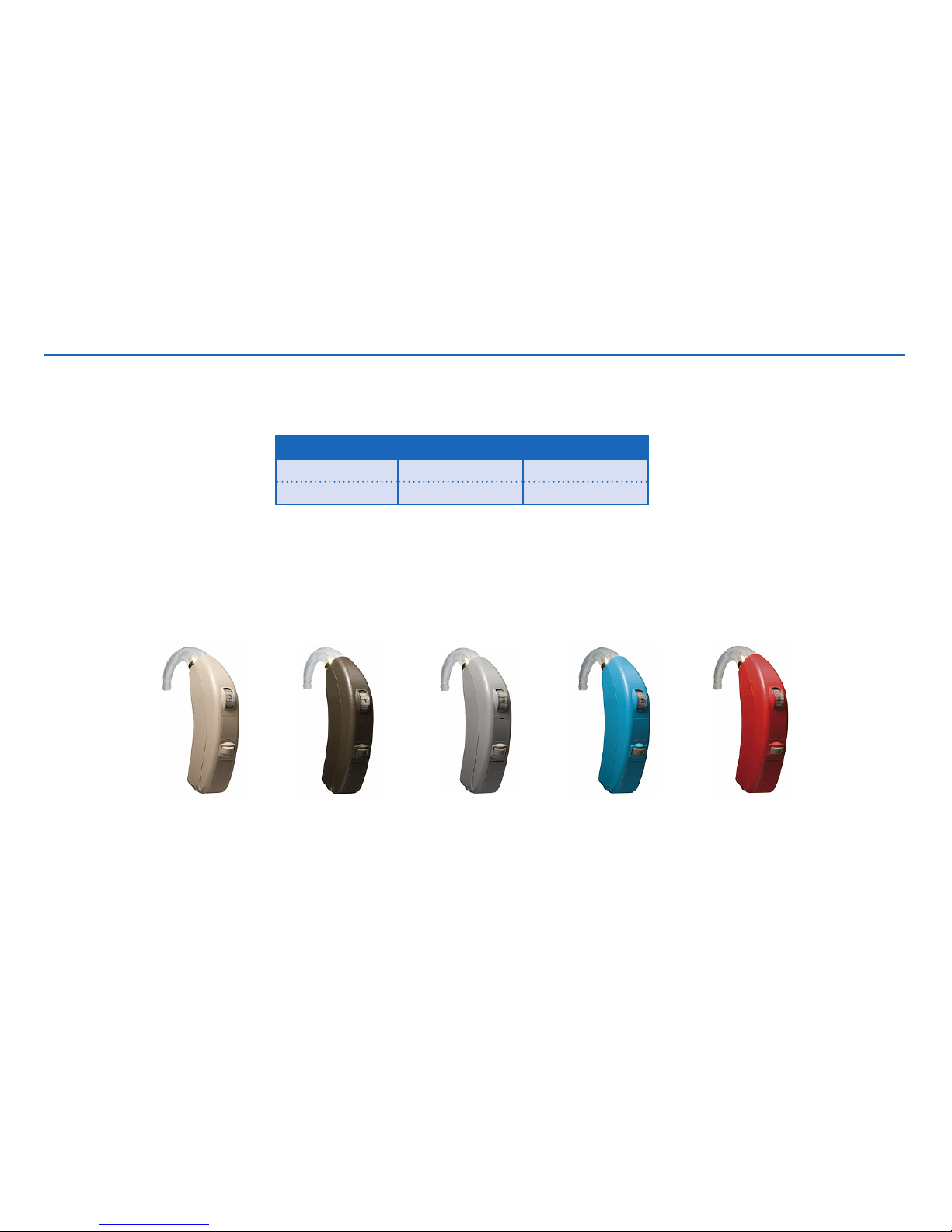
Model Data Sheet
SPARX SP90-VI 16499200
SPARX LITE SL90-VI 17141500
Beige Brown Blue RedCool Grey
Available in Beige, Dark Brown, Cool Grey, Blue & Red
Page 4
Doc 0155020 rev. C
Page 4 of 11
Part List
Item Part No
MIC. SUSPENSION 15297000
MICROPHONE 33M 15240900
MICROPHONE,COMPL 15988900
WIRE,ESW,AMBER,7X32U,14MM 15129714
WIRE,ESW,GREEN,7X32U,14MM 15129814
WIRE,ESW,RED,7X32U,14MM 15129614
PLASTIC BOLT 15284000
REC COMPL. 15989200
TELECOIL 16453100
VC NUT 15341000
VC COVER SILICONE 15282900
VC PLATE 15283000
VC 50K LINEAR PJ77 15751101
Item Part No
AMPL COMPL (SPARX/SPARX LITE) 17188401
HI-PRO PROG. CABLE CS44, R 9022 907 69019
HI-PRO PROG. CABLE CS44, L 9022 907 69029
TEST RING 15472600
TEST FIXTURE 16611100
TEST FRAME 1-21-65900
COATING SL 1367 16513100
RUBBER GLUE C-296336310 1901-061
ADULT HOOK W/O FILTER 15353200
ADULT HOOK WITH FILTER 15418400
BABY HOOK WITH FILTER 15427800
BABY HOOK W/O FILTER 15350900
FILTER-GR BF 1999 70930834
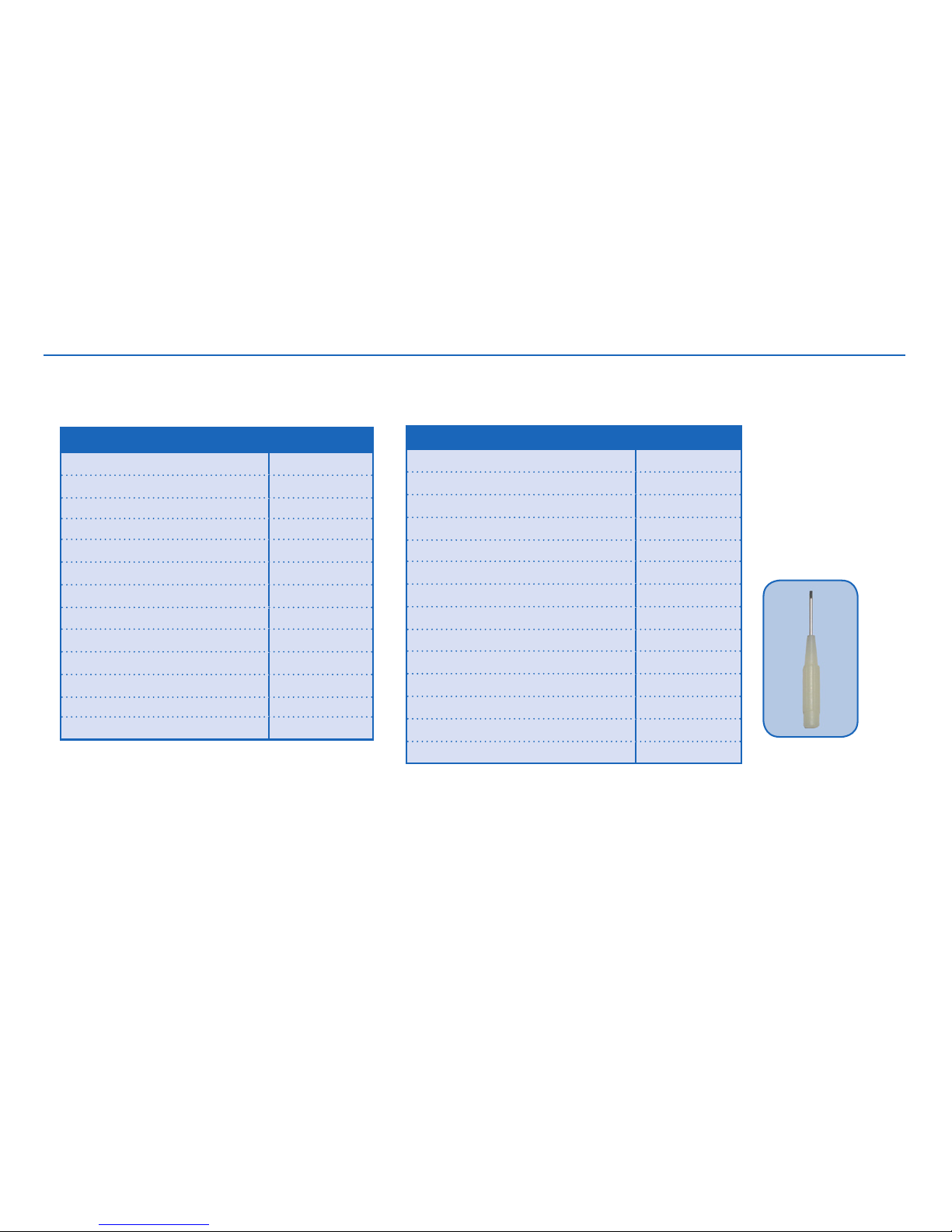
SCREW DRIVER,WHITE,45MM 8090-369
Screw driver
p/n 8090-369
Page 5

Doc 0155020 rev. C
Page 5 of 11
Part List - HSG Parts
HSG Parts
SPARX & SPARX LITE
For HI
BEIGE
For HI
BROWN
For HI
BLUE
For HI
COOL GREY
For HI
RED
TRANSP
(optional)
AU COVER,PTD 16429100 16429101 16429104 16429105 16429106 16429103
BAT DOOR,MOUNTED 15339800 15339801 15339804 15339805 15339806 N/A
HSG,BACK (VC SIDE) 15339400 15339401 15339404 15339405 15339406 N/A
HSG,FR,PTD,SP90-VI (SPARX) 16343200 16343201 16343204 16343205 16343206 N/A
HSG,FR,PTD,SL90-VI (SPARX LITE) 17104800 17104801 17104804 17104805 17104806 N/A
PC COVER,MOULDED 15339500 15339501 15339504 15339505 15339506 15339503
PC COVER,PTD,L** 16003100 16003101 16003104 16003105 16003106 16003103
PC COVER,PTD,R** 16003000 16003001 16003004 16003005 16003006 16003003
PB COVER 15893300 15893301 15893304 15893305 15893306 15893303
VC Cover Protection (optional) 15427400 15427401 N/A 15427402 N/A 15427403
VC Cover
Proctection
** To be mounted for indication of Right/Left side
Page 6
Doc 0155020 rev. C
Page 6 of 11
Item Part No
AUDIO-BOOT (for HI) 16987200
AUDIOBOOT,BICROS (for BICROS unit) 16987500
BICROS UNIT 16987600
CROS CABLE 20 CM 7000-409
CROS CABLE 22 CM 7000-439
CROS CABLE 24 CM 7000-469
CROS CABLE 26 CM 7000-459
CROS CABLE 28 CM 7000-479
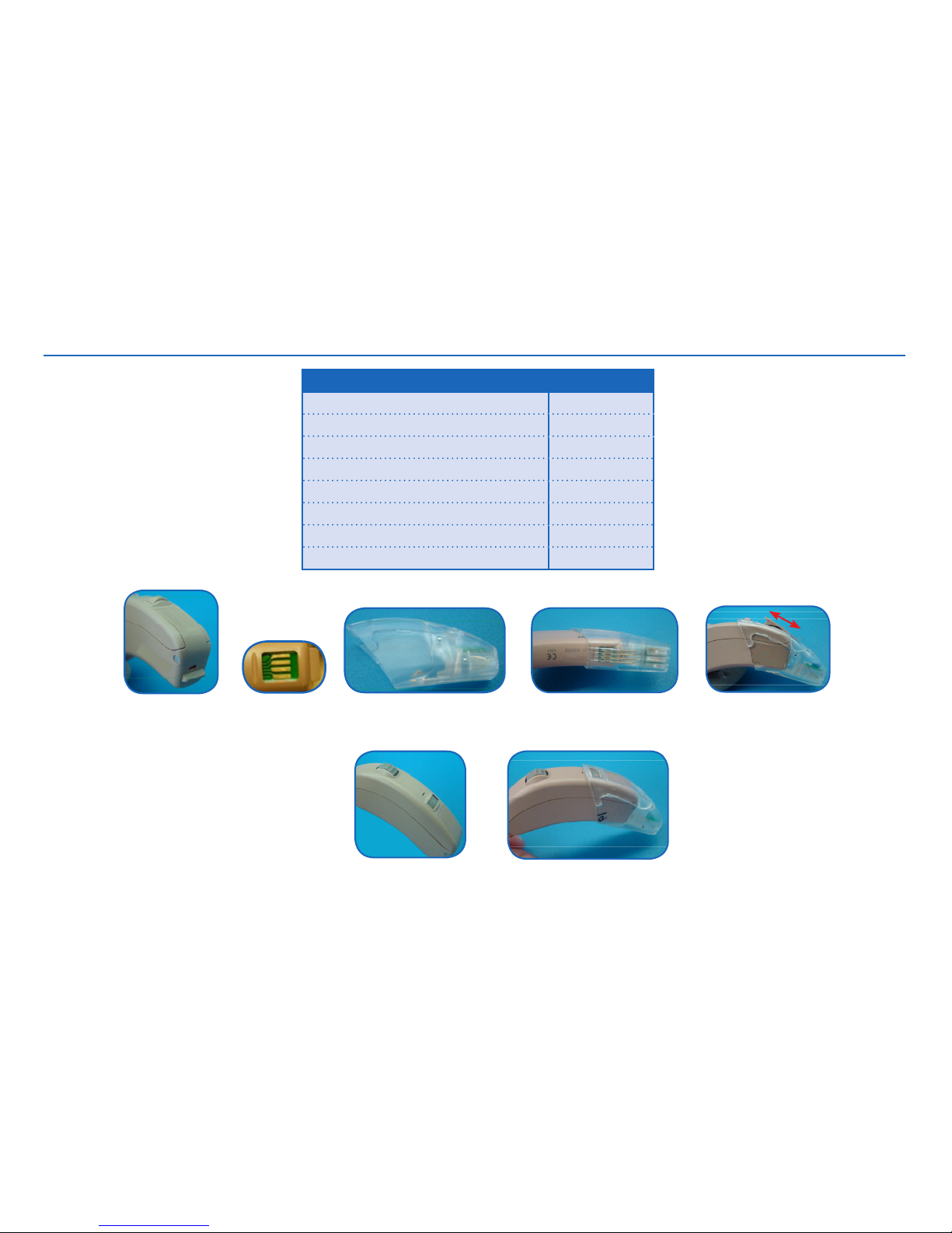
No need to
change batt door
Remove AU cover
to get access to
the 4 pins
Audio Boot for HI
p/n 16987200
Connect the Audio
Boot to the HI
Connect the Bicros Audio Boot to the Bicros Unit. Con-
nect the two set with a cros cable in a suitable length
CROS/BICROS System (4 contacts)
Page 7
Doc 0155020 rev. C
Page 7 of 11
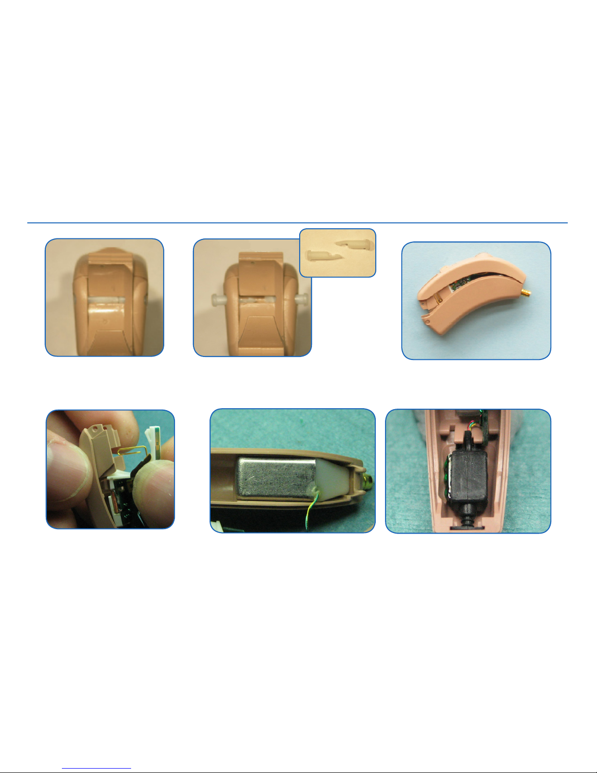
A pair of two plastic bolts
holds on to the batt. door
Use a tweezer to separate
the two plastic bolts and pull
them out. It is now possible to
remove the door
Gently pull the two housing parts from
each other
Plastic bolts
HI Disassembly
Gently pull out the amplier
Remove rec and mic from housing
Page 8
Doc 0155020 rev. C
Page 8 of 11
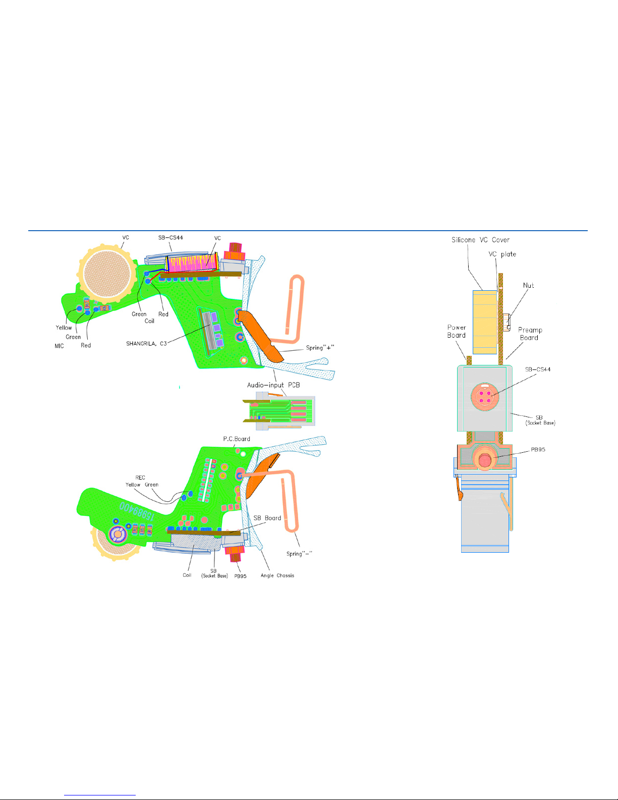
Amplier
Page 9
Doc 0155020 rev. C
Page 9 of 11
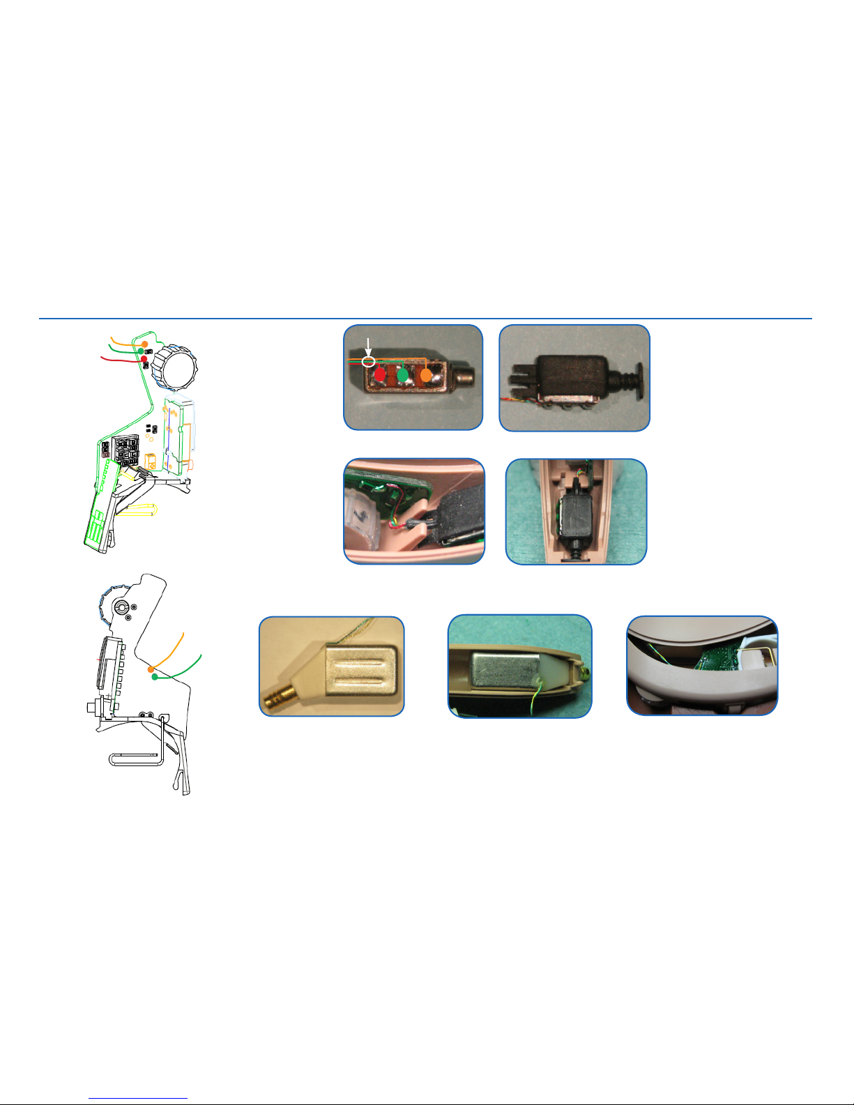
Replacement of Rec & Mic
Add rubber glue to x the wires
Connect wires and mount mic into suspension
The rec is delivered as rec
complete in box as shown
Route wires and make sure to place correctly in HSG
Place Rec in front HSG. Solder Rec wires to amplier and
route them well when adding HSG parts
Note: Apply coating material on solder pads after soldering
Page 10
Doc 0155020 rev. C
Page 10 of 11
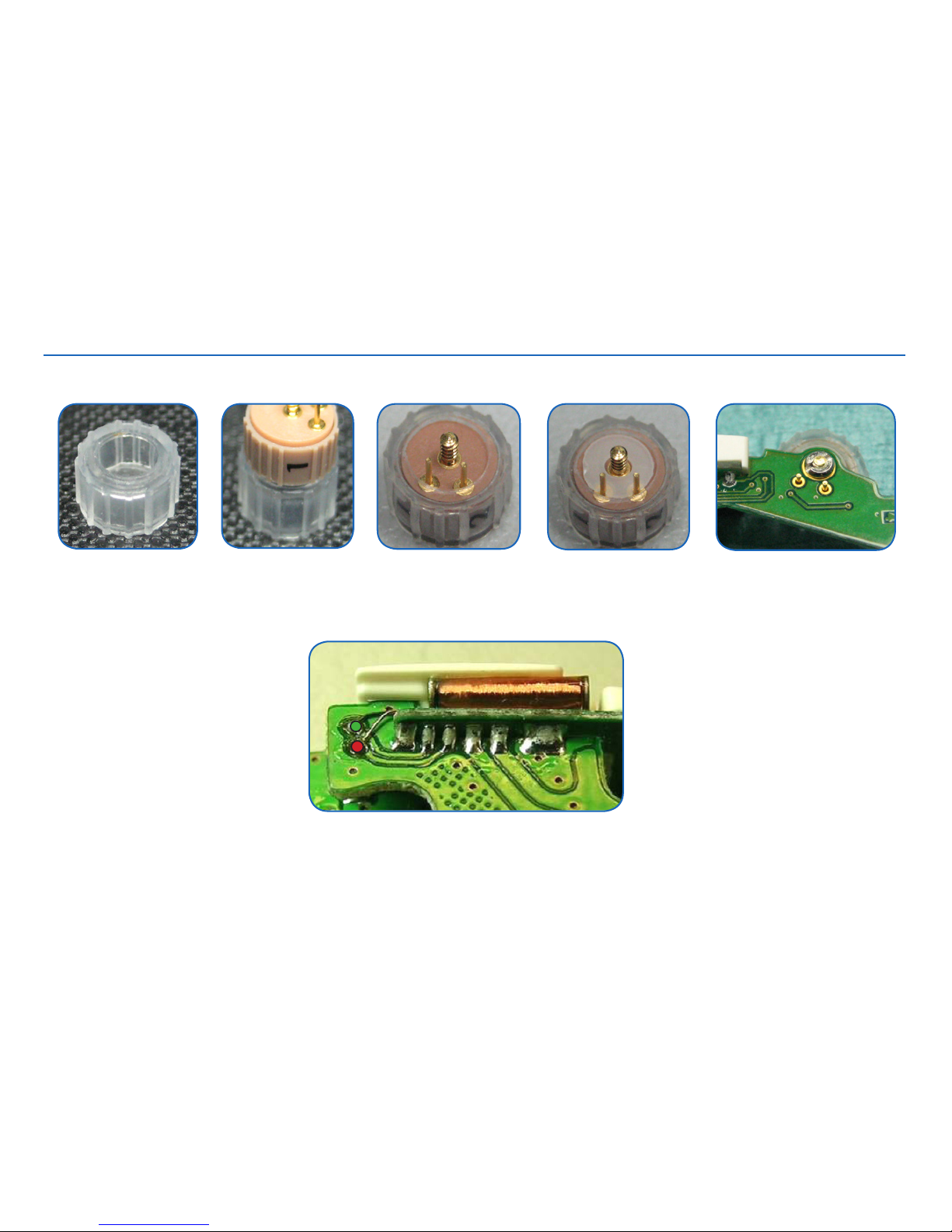
Replacement of TC & VC
Place the VC into the VC cover
VC cover
Add the VC plate
Mount VC to amplier. Screw
VC nut and solder the two
VC terminals
Add glue in the grove for TC. Place TC into the grove.
Connect TC wires to PCB and route them as shown
Note: Apply coating material on solder pads after soldering
Page 11
Doc 0155020 rev. C
Page 11 of 11
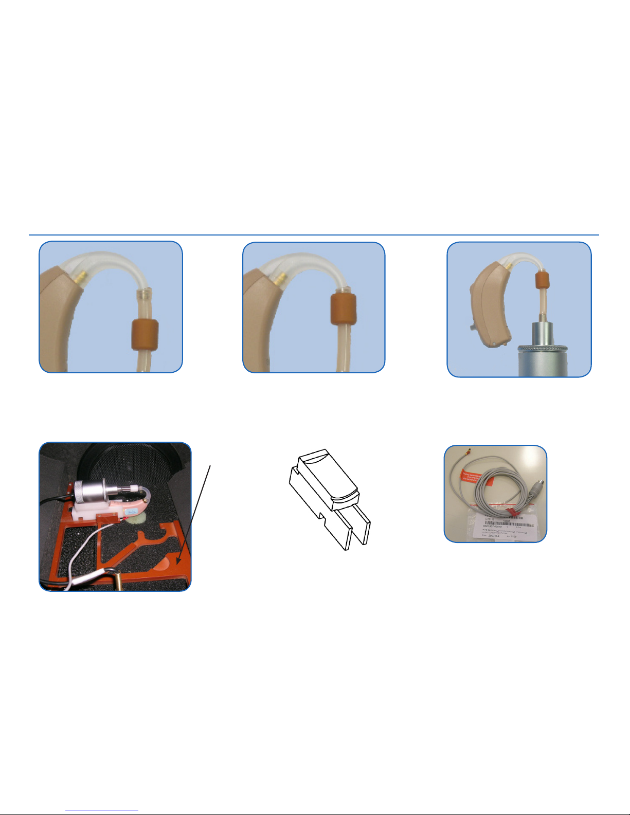
Test
When testing the HI a test ring is
needed to stabilize the HI. Place
the test ring on the 2cc coupler
tube
Push up the test ring to x the tube
and hook
Connect the CS44 prog cable and
place the HI and 2cc coupler in the
xture when placing it into the test
chamber
CS44 programming cable
Test xture, p/n 16611100
Test frame
p/n 1-21-65900
 Loading...