

Page 1
RE928X_Flexible Bus CDMA Communicator Page 1 of 10 4-Feb-15
24-hour Tech Support: (715)808-0164
www.ResolutionProducts.com
RE928X Flexible Bus CDMA Communicator
Features
• Connects panels to GSM Network
• Compatible with:
o Honeywell Vista® 15P and 20P
o DSC PowerSeries
o UTC NX [Future: Concord]
• Enables:
o Alarm Reporting
o Interactive Control Functions
o Ethernet data reliability
o Z-Wave Communicator included
Key Instructions
• The same unit works for Vista, Power Series, & UTC NX.
• Selectable switch determines panel compatibility.
• DO NOT MOUNT INSIDE METAL CAN – there are radios on the boards that
need to be in free-air to communicate.
• Communicator must be connected to a 12V power supply with battery
backup, such as the control panel's aux power output.
• The communicator should be mounted in a location that will optimize
cellular signal strength. Mount as high in the building as possible.
• RE927X communicates with the Vista 15P/20P via AUI device 2. Enable
AUI 2 in the Vista.
• The RE928X may be used as a backup for the RE920X or RE926X
communicators. Refer to “Using RE928X as a Backup”.
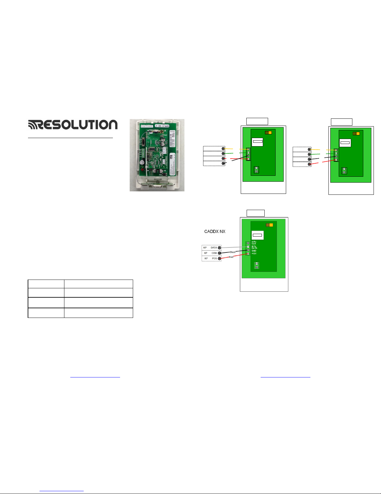
Wiring Instructions
NOTE: Some programming must be done PRIOR to connection
Maximum cable lengths shown in the table below, this assumes the
communicator is the only device attached to the cable. If multiple devices
share the same cable, the maximum cable length must be derated accordingly.
Wire Size (AWG) Maximum cable length to Control Panel
18 350
22 130
24 75
RE928X_Flexible Bus CDMA Communicator Page 2 of 10 4-Feb-15
24-hour Tech Support: (715)808-0164
www.ResolutionProducts.com
SIM Card
DSC
PowerSeries
YEL
GRN
AUX - BLK
AUX + RED
Green
Yellow
Red
Black
RE927X
A/Rx
CLK
B/Tx
DATA
GND
+12V
Honeywell
Vista 20P o r 15P
DATA OUT 7
DATA IN 6
AUX + 5
AUX - 4
Green
Yellow
Red
Black
RE927X
SIM Card
A/Rx
CLK
B/Tx
DATA
GND
+12V
RE928X
RE928X
RE928X
Page 2

RE928X_Flexible Bus CDMA Communicator Page 3 of 10 4-Feb-15
24-hour Tech Support: (715)808-0164
www.ResolutionProducts.com
Vista 20P and Vista 15P Programming:
Compatible Honeywell Panels:
Vista 20P (version 3.0 or later) (controls partition 1 only)
Vista 15P (version 3.0 or later)
1) Refer to server setup instructions and set up the account on the Dealer Portal.
2) Disarm the system (all partitions).
3) The RE928X automatically communicates with the Vista using AUI device 2.
The panel is probably defaulted to this. If not, enable AUI 2 in the *189 field.
4) Power down the Vista system.
5) Set RE928X panel selector switch to Honeywell: DSC CDX HW UTC
6) Connect the Vista and RE928X as shown in the Wiring Instructions above.
7) Apply power to the Vista 15P/20P system. It will automatically program.
a) Be sure ALL partitions are disarmed.
b) First, the Vista control panel will be busy for 50-60 seconds after powerup.
c) Then, the module will enable the following settings automatically:
IP/GSM device (*29)
Communicate to IP/GSM device first (*55)
Test Report off (*64)
Opening Report (*65)
Closing reports (*66)
Alarm cancel report (*68)
AC Power restoral report (*73)
Low Battery restoral report (*74)
Phone Monitor off (*92)
8) Finally, the keypad(s) should display "DISARMED Ready to Arm".
9) Installation is complete.
RE928X_Flexible Bus CDMA Communicator Page 4 of 10 4-Feb-15
24-hour Tech Support: (715)808-0164
www.ResolutionProducts.com
DSC Power Series Programming:
Compatible DSC Panels:
PC580 (Power 432) PC5020 (Power 864)
PC1555 (Power 632) PC1616
PC1555MX (Power 632) PC1832
PC5010 (Power 832) PC1864
PC5015 (Power 832)
1) Refer to server setup instructions and set up the account on the Dealer
Portal.
2) Using the system’s Installer Code:
a) Disable the Communicator ([380]:[1])
b) Disable the Telephone Line Monitor ([015]:[7])
c) Delete Telephone Numbers (programming section 301-303)
3) Verify Alarm report codes are setup properly for zones that are being used,
1-64 (programming section 320-349). System will report as Burg(130) if
programmed as FF.
4) If using Aux input (PGM2) verify Aux input report codes are setup properly
(programming section 329:4). System will report as Fire (110) if
programmed as FF.
5) All other reports are hardcoded in the gateway and cannot be changed
regardless of what is entered in the programmed location.
6) Format and account number have no effect on reporting.
7) Disarm the system (all partitions)
8) Power down the DSC system.
9) Set RE928X panel selector switch to DSC: DSC CDX HW UTC
10) Connect the DSC Panel and RE928X as shown in the Wiring Instructions
above.
11) Apply power to the DSC system.
12) The DSC control panel will begin automatic configuration. This can take up
to 2 minutes.
13) Installation complete.
Page 3

RE928X_Flexible Bus CDMA Communicator Page 5 of 10 4-Feb-15
24-hour Tech Support: (715)808-0164
www.ResolutionProducts.com
Reporting Codes for DSC panels:
The following table shows all events reported when connected to a DSC Panel.
Event Report Code
AC Fail/Restore
301
Panel Low Battery/Low Battery
Restore
302
Opening/Closing Report
400
Cancel Report
406
Zone Alarm
See below
Automatic Contact ID is not supported. Manually programmed reporting codes
are only supported for alarms on zones 1-64 ([320] – [324]) and for alarms on
the PGM2/Aux input ([329]:[4]). The PGM2/Aux input is reported as zone
number 99.
If Report Codes have not been manually programmed for zone alarms, zone
alarm reporting codes default to:
• Any zone alarm (zones 1-64): Code 1130 (Burglary)
• PGM2/Aux input (zone 99, likely a 2-wire Smoke): Code 1110 (Fire)
Be sure to verify that all codes are being properly reported to the central
station after you have installed the communicator module or modified any
reporting program settings in the DSC installer programming menu.
Caddx NX Programming:
Compatible with all NX series panels
1. Refer to server setup instructions and setup account on the Dealer Portal.
2. Disarm the system (all partitions).
3. Power down the NX system.
4. Set the RE928X panel selector switch to CDX: DSC CDX HW UTC
5. Connect the NX panel and the RE928X as shown in the Wiring Instructions
above.
6. Apply power to the NX system. During this process, the communicator will
program the following settings:
Enable Opening and Closing reports
Set Telephone Line Cut delay to 0 (no TLM)
7. Installation complete.
Important: Do not attempt to enter program mode until the CS and Platform
LEDs have stopped flashing.
Additional Notes for NX installations:
1. Some NX panels limit the number of non-keypad devices they support. Be
sure that the panel you are connecting the communicator to does not have
more than the number of support devices connected.
2. User codes that are added to the system or edited thru the communicator
will have the default or previous partitions enabled. If you desire the users
to have different partitions enabled, you will need to modify the partitions
thru the NX keypad.
RE928X_Flexible Bus CDMA Communicator Page 6 of 10 4-Feb-15
24-hour Tech Support: (715)808-0164
www.ResolutionProducts.com
TroubleShooting the Panel Connection:
If the “CS or “Platform” LEDs are blinking, here are possible
problems:
Incorrect wiring
Incorrect panel switch position
Unsupported panel version
Unsupported panel model
AUI not enabled
AUI used for some other function
LRR not enabled
Another LRR or IP/GSM device connected to panel bus
Panel is in Installer Program Mode
Factory Default Button
This button has two functions:
a) Holding this button for approximately 5 seconds will reset the RE928X
Communicator.
b) Holding this button for approximately 10 seconds (LEDs will flash off
twice) will set the RE928X to factory defaults.
Operation
Event Reporting:
Events are reported to both the monitoring receiver and the interactive
server. All events use Contact ID reporting codes. The following events
are reported by default:
Alarms System Low Battery
Alarm cancels System Low Battery Restoral
Openings AC Power Fail (delayed by some panels)
Closings AC Power Restoral (delayed by some panels)
Vista Only:
Additional events can be enabled for reporting if desired, by enabling
the desired event reports in system programming.
Interactive Control:
The system may be controlled remotely through the interactive platform.
The arm/disarm control and status applies to partition 1 only.
Z-Wave
Z-Wave devices can be controlled via the Interactive function.
Siren (Future capability)
Resolution Wireless Siren will be useable to indicate alarm and statuses.
Page 4
RE928X_Flexible Bus CDMA Communicator Page 7 of 10 4-Feb-15
24-hour Tech Support: (715)808-0164
www.ResolutionProducts.com
CDMA Signal Strength LEDs (A minimum of 2 Signal Strength LEDs is recommended)
LEDs CDMA Signal Strength
0 0-6 - Bad
1 7-9 - Marginal
2 10-12 - Good
3 13-17 - Better
4 17+ - Best
Using the RE928X as a Backup
In backup mode, the RE928X will send events to the Central Station server and to
the interactive server, in the event that the Primary communicator is unable to do so.
In Backup Mode, only event reporting is supported.
Configuring RE928X Backup Mode
Wire both the RE928X and the primary communicator (RE920X or RE926X)
to the alarm panel's data bus (as indicated in the wiring instructions)
When power is applied to the alarm panel, the RE928X will detect the presence of the
primary communicator within 30 seconds, and enters Backup Mode. If no Primary
Communicator is detected, the RE928X will enter Primary Mode.
NOTE: The subscriber account must be configured to use both Primary and
Backup gateways. Refer to the Dealer Portal User Guide for details.
Power LED
The rate the Power LED flashes indicates current operating mode
• Flashing every 1 second = Primary Mode
• Flashing every 3 seconds = Backup Mode
RE928X_Flexible Bus CDMA Communicator Page 8 of 10 4-Feb-15
24-hour Tech Support: (715)808-0164
www.ResolutionProducts.com
LEDs
Bus Board LEDs
Indication
Green On when the board is powered and
running
Red May flicker occasionally when module talks to panel.
GSM Card LEDs
Indication
Power
(Green)
ON and Flashing once per second when the board is powered and running
in Primary Mode
ON and Flashing once every three seconds when the board is powered and
running in Backup Mode
CDMA
(Red)
ON when the unit is registered with the local
CDMA network
CS
(Red)
O
N when the connection to the
central station is established
Flashes when there is a problem detecting the Panel type
Platform
(Amber)
ON w
hen the connection to the Panel
and connection to the
interactive
server is established
Flashes when there is a problem communicating with the panel
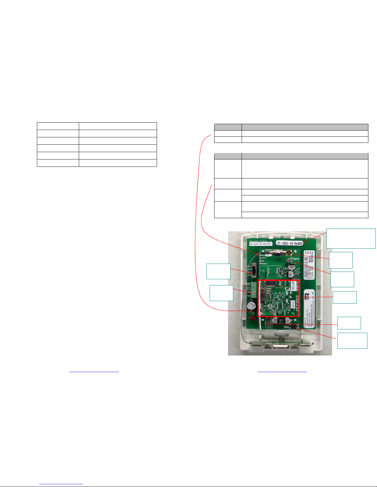
Picture
Z-Wave
Module
Revert to
Factory
Default Button
CDMA
Antenna
Connector
Panel
Selector
Switch
Data Bus
Connector
Z-Wave
Antenna
Board Revision
see
Revision Functionality
Table
Signal
Strength
LEDs
Page 5

RE928X_Flexible Bus CDMA Communicator Page 9 of 10 4-Feb-15
24-hour Tech Support: (715)808-0164
www.ResolutionProducts.com
Specifications
Current Draw: 220 mA Nominal
Temperature Range: 0F to 120F
Housing dimensions: 4x6x1 inches
Specifications subject to change without notice.
Revision Functionality Table
Revision on top left
of main board
Functionality
57-0027-05_RevA00
Vista15P/20P Compatibility Only
57-0027-05_RevA01
Or Later
Vista15P
/20P & DSC
PowerSeries
Compatible
Notices
“GE”, “Honeywell”, “DSC”, “2GIG” and “Napco” are trademarks owned by General Electric
Company, Honeywell International Inc., Tyco Safety Products Canada LTD, 2GIG Technologies
Inc., and NAPCO Security Systems, Inc., respectively.
Resolution Products, Inc. products will function with one of either GE, Honeywell, DSC or
Napco systems. However, no Resolution product is produced by, endorsed by, nor is officially
associated with GE, Honeywell, DSC or Napco. Resolution recommends verifying proper
enrollment and operation, per control panel installation instructions, at installation.
Warranty
Resolution Products, Inc. will replace products that are defective in their first five (5) years.
FCC Notice
This device complies with Part 15 of the FCC rules. Opera tion is subject to the
following two conditions:
(1)This device may not cause harmful interference.
(2)This device must accept any interference that may be receiv ed, including
interference that may cause undesired operation.
Changes or modifications not expressly approved by the Resolution Engineering, Inc.
could void the user's authority to operate this equipment.
FCC ID: U5X-RE928
This device contains FCC ID: QISMU509C
RF Exposure:
To satisfy FCC RF Exposure requirements for mobile and base station transmission
devices, a separation distance of 20 cm or more should be maintained between the
antenna of this device and persons during operation. To ensure compliance, operation
at closer than this distance is not recommended.
The antenna(s) used for this transmitt er must not be co-located or operating in
conjunction with any other antenna or transmitter.
RE928X_Flexible Bus CDMA Communicator Page 10 of 10 4-Feb-15
24-hour Tech Support: (715)808-0164
www.ResolutionProducts.com
IC Notice
This device complies with Industry Canada license-exempt RSS standard(s). Operation is
subject to the following two conditions:
(1)This device may not cause interference, and
(2)This device must accept any interference, including interference that may cause
undesired operation of the device.
Le présent appareil est conforme aux CNR d'Industrie Canada applicables aux ap pareils
radio exempts de licence. L'exploitation est autorisée aux deux conditions suivantes :
(1)l'appareil ne doit pas produire de brouillage, e t
(2)l'utilisateur de l'appareil doit accepter tout brouillag e radioélectrique subi,
même si le brouillage est susceptible d'en compromettre le fonctionnement.
Model: RE928X
IC: 8310A-RE928
This device contains IC: 6369A-MU509C
Under Industry Canada regulations, this radio transmitter may only operate using an
antenna of a type and maximum (or lesser) gain approved for the transmitter by
Industry Canada. To reduce potential radio interference to other users, the antenna
type and its gain should be so chosen that the equivalent isotropically radiated power
(e.i.r.p.) is not more than that necessary for successful communication.
Conformément à la réglementation d'Industrie Canada, le présent émetteur radio peut
fonctionner avec une antenne d'un type et d'un gain m aximal (ou inférieur)
approuvé pour l'émet teur par Industrie Canada. Dans le but de réduire les risques de
brouillage ra dioélectrique à l'intention des autres utilisateurs, il faut choisir le
typed'antenne e t son gain de sorte que la puissance isotrope rayonnée équivalente
(p.i.r.e.) ne dépasse p as l'intensité nécessaire à l'établissement d'une communication
satisf aisante.
 Loading...