

Resolution RE927-03-00 Series Manual
24-hour Tech Support Line: (715)808-0164
RE927X-03-00 Flexible Bus 3G GSM Communicator
Features
• Connects panels to GSM Network
• Compatible with:
o Honeywell Vista® 15P and 20P
o DSC PowerSeries
o CADDX NX
o UTC Concord 4
• Enables:
o Alarm Reporting
o Interactive Control Functions
o Z-Wave Communicator included
Key Instructions
• The same unit works for Vista, Power Series, CADDX NX, & UTC Concord 4.
• Selectable switch determines panel compatibility.
• DO NOT MOUNT INSIDE METAL CAN – there are radios on the boards that
need to be in free-air to communicate.
• Communicator must be connected to a 12V power supply with battery
backup, such as the control panel's aux power output.
• The communicator should be mounted in a location that will optimize
cellular signal strength. Mount as high in the building as possible.
• RE927X communicates with the Vista 15P/20P via AUI device 2. Enable
AUI 2 in the Vista.
• The RE927X may be used as a backup for the RE920X or RE926X
communicators. Refer to “Using RE927X as a Backup”.
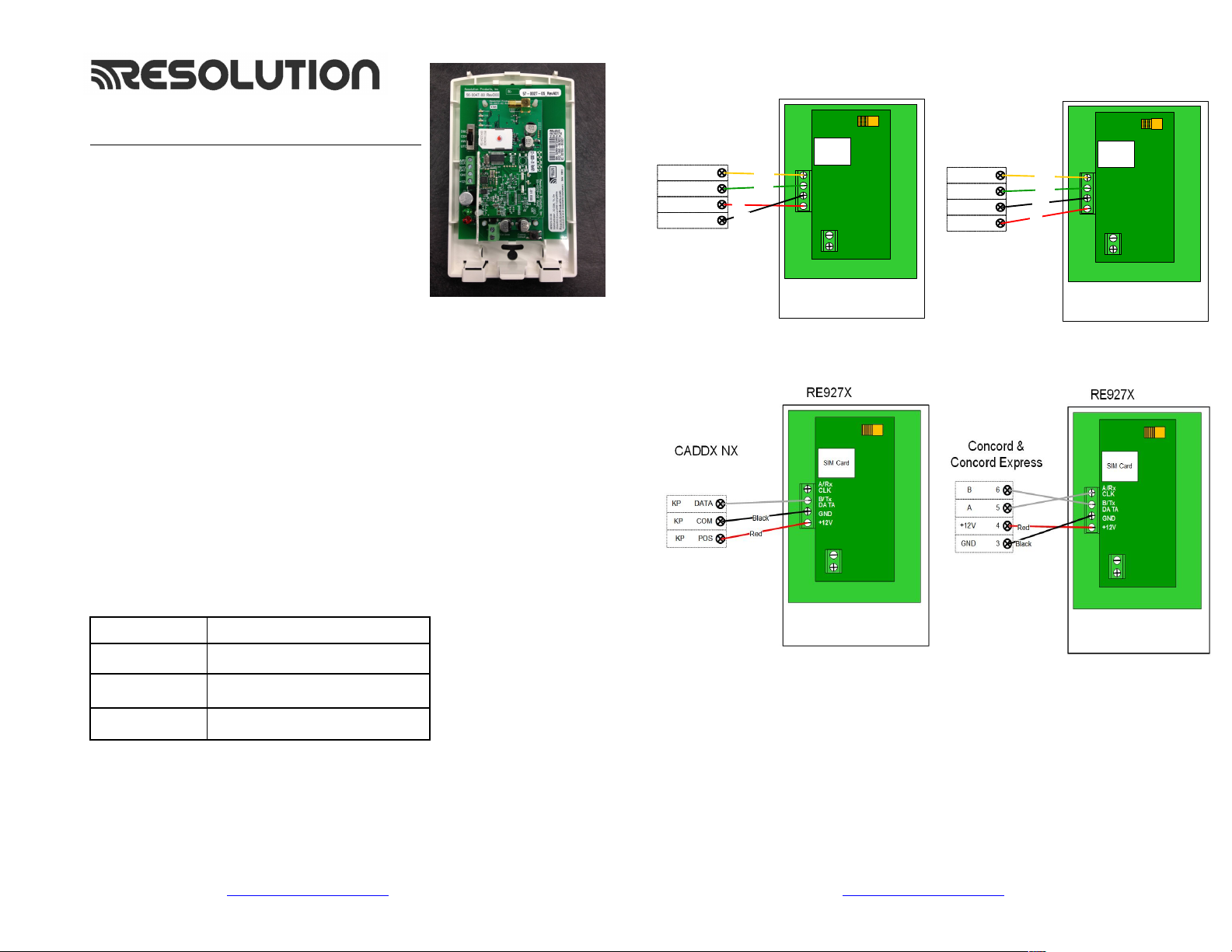
Wiring Instructions
NOTE: Some programming must be done PRIOR to connection
Maximum cable lengths shown in the table below, this assumes the
communicator is the only device attached to the cable. If multiple devices
share the same cable, the maximum cable length must be derated accordingly.
Wire Size (AWG) Maximum cable length to Control Panel
18 350
22 130
24 75
RE927X-03-00_Flexible Bus 3G GSM Communicator Page 1 of 10 17-Aug-15
24-hour Tech Support: (715)808-0164
www.ResolutionProducts.com
Honeywell
DATA O UT 7
DATA I N 6
AUX + 5
AUX - 4
Vista 20P or 15P
RE927X-03-00_Flexible Bus 3G GSM Communicator Page 2 of 10 17-Aug-15
Red
Black
Yellow
Green
RE927X
SIM Card
A/Rx
CLK
B/Tx
DATA
GND
+12V
PowerSeries
AUX - BLK
AUX + RED
24-hour Tech Support: (715)808-0164
www.ResolutionProducts.com
DSC
YEL
GRN
Red
Yellow
Green
Black
RE927X
SIM Card
A/Rx
CLK
B/Tx
DATA
GND
+12V

Vista 20P and Vista 15P Programming:
Compatible Honeywell Panels:
Vista 20P (version 3.0 or later) (controls partition 1 only)
Vista 15P (version 3.0 or later)
1) Refer to server setup instructions and set up the account on the Dealer Portal.
2) Be sure to add a contact that uses the system MASTER CODE to the account before
connecting the module. This will ensure the module can properly communicate
with and configure required system settings.
3) Disarm the system (all partitions).
4) The RE927X automatically communicates with the Vista using AUI device 2.
The panel is probably defaulted to this. If not, enable AUI 2 in the *189 field. If a
device is already using AUI 2, that device must be moved to another AUI address (AUI
1, for Vista 15P, AUI 1, 3 or 4 for Vista 20P
5) The 2nd entry in the *91 field must be set to 0 or 1 based on the current call
waiting disable setting (0 = call waiting disable not used, 1 = call waiting disable is
used). Either of these settings disable the RIS feature and allows the RE927X to
communicate with the Vista panel. Vista panels of V10.24 or later no longer have a
RIS option, no action is required with these panels.
a) Vista 15p and 20p panel versions 10.21 and later have the keypad lockout feature enabled
by default. It is recommended that this feature be disabled to prevent possible keypad
lockout conditions if the system master code in the IGM is not synchronized with the master
code in the Vista panel. Use programming option *188 to disable keypad lockout.
b) If it is required to have the keypad lockout feature enabled, it is critical that the system
master code be set up as a contact for this account before connecting the module to the panel
(see Step 2 above). Also all changes to the system master code must be done at the user portal
or dealer portal, not at the keypad. Failing to do this may result in a keypad lockout condition.
6) Power down the Vista system.
7) Set RE927X panel selector switch to Honeywell: DSC CDX HW UTC
8) Connect the Vista and RE927X as shown in the Wiring Instructions above.
9) Apply power to the Vista 15P/20P system. It will automatically program.
a) Be sure ALL partitions are disarmed.
b) First, the Vista control panel will be busy for 50-60 seconds after powerup.
c) Then, the module will enable the following settings automatically:
IP/GSM device (*29) = 1 (enabled)
Communicate to IP/GSM device first (*55) = 1 (IP/GSM first)
Opening Report (*65) = 1 (enabled)
Closing reports (*66) = 1, 1 (stay closing & away closing reports enabled)
Alarm cancel report (*68) = 1 (enabled)
AC Power restoral report (*73) = 1 (enabled)
Low Battery restoral report (*74) = 1 (enabled)
Phone Monitor (*92) = 0 (disabled)
10) Finally, the keypad(s) should display "DISARMED Ready to Arm".
11) Installation is complete.
DSC Power Series Programming:
Compatible DSC Panels:
PC580 (Power 432) PC5020 (Power 864)
PC1555 (Power 632) PC1616
PC1555MX (Power 632) PC1832
PC5010 (Power 832) PC1864
PC5015 (Power 832)
1)
Refer to server setup instructions and set up the account on the Dealer Portal.
2)
Be sure to add a contact that uses the system MASTER CODE to the account before
connecting the module. This will ensure the module can properly communicate
with and configure required system settings.
3)
Using the system’s Installer Code:
a) Disable the Communicator ([380]:[1])
b) Disable the Telephone Line Monitor ([015]:[7])
c) Delete Telephone Numbers (programming section 301-303)
d) Verify Alt Comm ([351]:[5]) is enabled
e) Verify T-Link is Disabled ([382]:[5])
f) Verify Master Code Not Changeable is Disabled ([015]:[6])
g) Verify Access Code Required for *1, *2, *3 menus is disabled ([022]:[1])
h) Verify that keypad lockout is either zero(disabled) or higher than 6 ([012])
i) If you have removed any bus devices, perform a Module Supervision Reset ([902])
4)
Verify Alarm report codes are setup properly for zones that are being used, 1-64
(programming section 320-349). System will report as Burg(130) if programmed as
FF.
5)
If using Aux input (PGM2) verify Aux input report codes are setup properly
(programming section 329:4). System will report as Fire (110) if programmed as FF.
6)
To enable reporting of the Period Test Transmission, program the “periodic Test
Transmission” ([348]:[4]) and the “Periodic Test Transmission with Trouble”
([348]:[3]) reporting codes to “02”
7)
All other reports are hardcoded in the gateway and cannot be changed regardless
of what is entered in the programmed location.
8)
Format and account number have no effect on reporting.
9)
Disarm the system (all partitions)
10)
Power down the DSC system.
11)
Set RE927X panel selector switch to DSC: DSC CDX HW UTC
12)
Connect the DSC Panel and RE927X as shown in the Wiring Instructions above.
13)
Apply power to the DSC system.
14)
The DSC control panel will begin automatic configuration. This can take up to 2
minutes.
15)
Installation complete.
RE927X-03-00_Flexible Bus 3G GSM Communicator Page 3 of 10 17-Aug-15
24-hour Tech Support: (715)808-0164
www.ResolutionProducts.com
RE927X-03-00_Flexible Bus 3G GSM Communicator Page 4 of 10 17-Aug-15
24-hour Tech Support: (715)808-0164
www.ResolutionProducts.com
 Loading...