

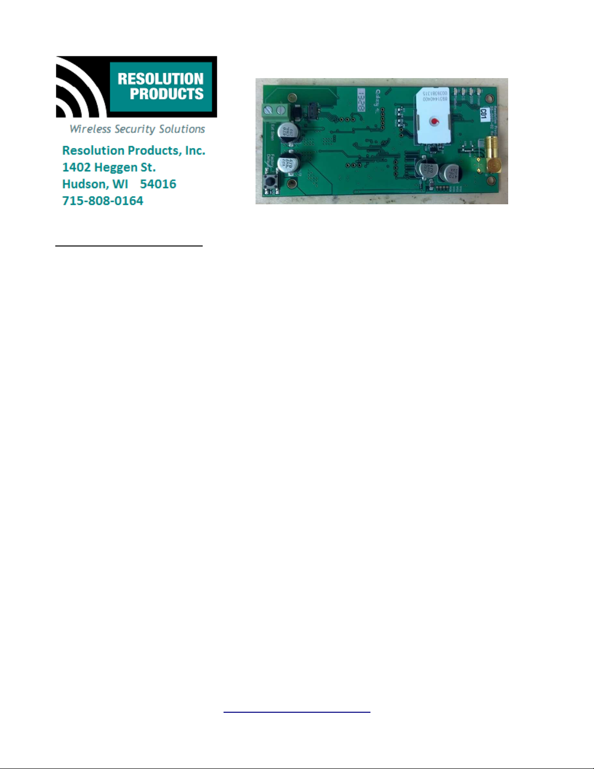
RE927S 3G GSM Module
Features
•
Connects in the daughter board slot of a GE SimonXT security panel.
•
Allows reporting of alarm status conditions over 3G GSM cell phone towers.
•
Allows control of system functions (arming, disarming, etc.) over GSM connection.
•
Allows control of additional wireless sirens in alarm conditions.
•
Superior 3G GSM reception with included antenna in low coverage areas!
Key Instructions
•
Power down the SimonXT panel, and open the back cover.
•
Install the RE927S unit into the slot at the back of the panel.
•
Connect the included GSM antenna to the RE927S board connector. String the antenna
through the hole on the bottom of the panel.
•
Power up the panel, make sure the green power LED on the RE927S board turns on.
•
Wait for the Red GSM LED to turn on to show that a GSM connection is established.
•
Close the back cover on the panel.
LED Operation
•
The GSM LED lights when proper connection has been established with the local GSM
network towers.
•
Power LED lights green when powered and shows a 'heartbeat' for processor functioning
correctly.
•
CS LED lights when connected to Central Alarm Reporting Station
•
Platform LED lights when connected to interactive platform website.
Specifications
Panel Compatibility: GE/Interlogix SimonXT
Power Supply: 9-18V DC, minimum 1.5A.
Current draw: 50-500mA, normal operation, 2.7A peak
PCB dimensions: 1.9 x 4.1 inches
RE927S 3G GSM Module User Manual Page 1 of 5
www.resolutionproducts.com
Specifications subject to change without notice.
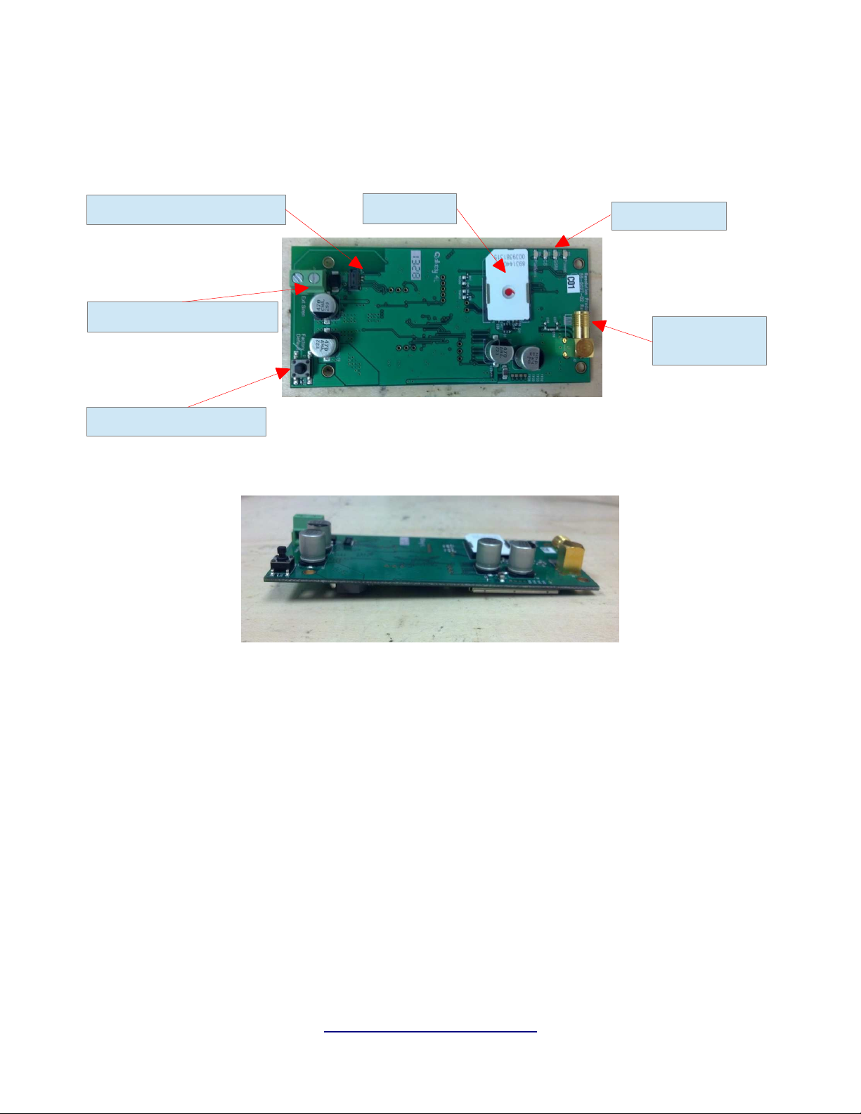
Internal Pictures
Top view:
Daughter Board Connector
External Siren Connector
Factory Default Switch
Side view:
SIM Card
Status LEDs
GSM Antenna
Connector
RE927S 3G GSM Module User Manual Page 2 of 5
www.resolutionproducts.com

OEM Installation Instructions
The RE927S module is installed in the GE SimonXT host as follows:
1. The SimonXT panel should be powered down, with battery unplugged.
2. Open the panel and expose the back.
3. Unwrap the module from its packaging and carefully slide the module underneath the
plastic tabs at the top of the expansion slot.
4. Gently press down on the bottom of the module so that it engages with the connector on
the panel.
5. Secure the module in place using four screws in the corner holes.
6. Connect the GSM antenna and wire it through the hole in the bottom of the panel as shown
in the picture below. Do not over tighten the antenna, the connector may break, finger
tighten, no tools needed.
7. Before closing up the back of the panel, reconnect the battery and power up the panel.
8. Power up the panel, check to make sure the power led on the RE927 is on. Wait up to a
few minutes for the red GSM led to turn on indicating a proper connection.
9. Close the back cover of the panel.
10. Connect to the module using the configuration serial number and configure the module's
information with the configuration web interface.
RE927S 3G GSM Module User Manual Page 3 of 5
www.resolutionproducts.com

Notices:
“GE” is a trademark owned by General Electric Company. “Interlogix” is a trademark of UTC.
This Resolution Product is not produced by, endorsed by, or officially associated with GE or UTC. Resolution
recommends verifying operation at installation.
This product is only usable with the GE/Interlogix SimonXT alarm panel.
FCC Notice
This device complies with Part 15 of the FCC rules. Operation is subject to the following two conditions:
(1)This device may not cause harmful interference.
(2)This device must accept any interference that may be received, including
interference that may cause undesired operation.
Changes or modifications not expressly approved by the Resolution Engineering, Inc. could void the user's
authority to operate this equipment.
FCC ID: U5X-RE927
This device contains FCC ID: QISMU509C
RF Exposure:
To satisfy FCC RF Exposure requirements for mobile and base station transmission devices, a separation
distance of 20 cm or more should be maintained between the antenna of this device and persons during
operation. To ensure compliance, operation at closer than this distance is not recommended.
The antenna(s) used for this transmitter must not be co-located or operating in conjunction with any other
antenna or transmitter.
RE927S 3G GSM Module User Manual Page 4 of 5
www.resolutionproducts.com

IC Notice
This device complies with Industry Canada license-exempt RSS standard(s). Operation is
subject to the following two conditions:
Le présent appareil est conforme aux CNR d'Industrie Canada applicables aux appareils
radio exempts de licence. L'exploitation est autorisée aux deux conditions suivantes :
Model: RE927S
IC: 8310A-RE927
This device contains IC: 6369A-MU509C
Under Industry Canada regulations, this radio transmitter may only operate using an antenna of a type and
maximum (or lesser) gain approved for the transmitter by Industry Canada. To reduce potential radio
interference to other users, the antenna type and its gain should be so chosen that the equivalent
isotropically radiated power (e.i.r.p.) is not more than that necessary for successful communication.
Conformément à la réglementation d'Industrie Canada, le présent émetteur radio peut fonctionner avec une
antenne d'un type et d'un gain maximal (ou inférieur) approuvé pour l'émetteur par Industrie Canada. Dans
le but de réduire les risques de brouillage radioélectrique à l'intention des autres utilisateurs, il faut choisir
le type d'antenne et son gain de sorte que la puissance isotrope rayonnée équivalente (p.i.r.e.) ne dépasse pas
l'intensité nécessaire à l'établissement d'une communication satisfaisante.
(1)This device may not cause interference, and
(2)This device must accept any interference, including interference that may cause
undesired operation of the device.
(1)l'appareil ne doit pas produire de brouillage, et
(2)l'utilisateur de l'appareil doit accepter tout brouillage radioélectrique subi,
même si le brouillage est susceptible d'en compromettre le fonctionnement.
RE927S 3G GSM Module User Manual Page 5 of 5
www.resolutionproducts.com
 Loading...