

RE922 GSM Module
Features
• Connects in daughterboard slot of SimonXT panel
• Allows reporting of alarm and status conditions over GPRS connection
• Allows control of system functions (arming, disarming, etc) over GPRS
connection
Key Instructions
• Install RE922 unit in slot at back of panel
• Power up the panel
• Connect antenna cable
LED Operation
• "Power" LED lights green when powered and shows heartbeat for
processor functioning correctly
• "GSM" LED lights when proper connection has been established with the
GSM network
• "CS" LED lights when connected to Central Alarm Reporting Station
• "Platform" LED lights when connected to interactive platform website
Specifications
Panel Compatibility: GE/Interlogix SimonXT
External supply: 9-18V DC
RE922_GSM_Module_Manual v2.odt
Page 1 of 4 7-17-12
www.ResolutionProducts.com
Current draw: 50mA nominal, 1.5A peak.
PCB dimensions: 1.9 x 4.1 inches
Antenna: Quad-band, supplied by OEM Customer
Specifications subject to change without notice.
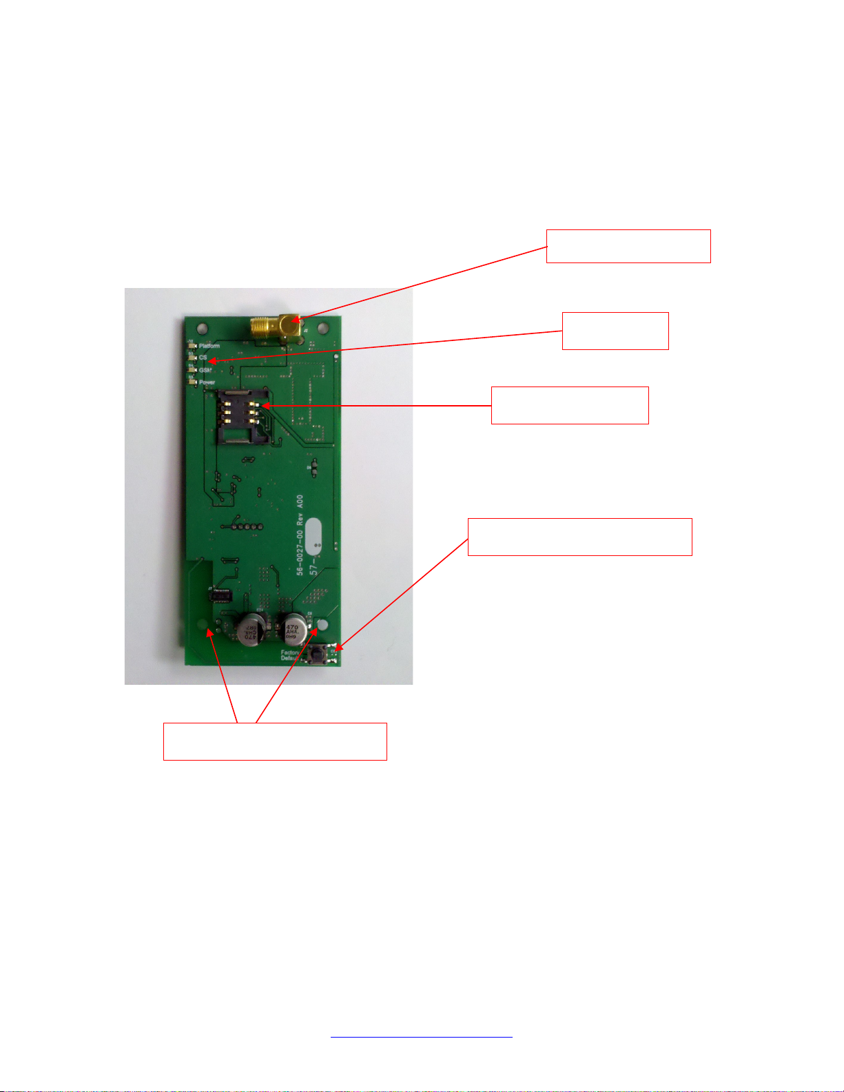
Internal Picture
Antenna Connector
Status LEDs
SIM Card Holder
Mounting Holes
Factory Default Switch
RE922_GSM_Module_Manual v2.odt
Page 2 of 4 7-17-12
www.ResolutionProducts.com

OEM Installation Instructions
The RE922 module is installed in the SimonXT host as follows:
1. The SimonXT should be powered down.
2. Expose the back of the panel as shown in the following picture.
3. The module is installed in the expansion slot on the left, as shown in the
picture.
4. Unwrap the module from its packaging and carefully slide the module
underneath the plastic tabs at the top of the expansion slot.
5. Gently press down on the bottom of the module so that it engages with
the connector on the panel.
6. Secure the module in place using four screws in the provided holes.
7. Attach antenna cable to the connector and arrange it so that it exits the
enclosure with out strain.
8. Connect to the module using the configuration IP Address and configure
the module's IP Addresses and other information with the configuration
interface.
RE922_GSM_Module_Manual v2.odt
Page 3 of 4 7-17-12
www.ResolutionProducts.com

Notices
“GE” is a trademark owned by General Electric Company. "Interlogix" is a trademark of UTC.
This Resolution product is not produced by, endorsed by, or officially associated with GE or
UTC. Resolution recommends verifying operation at installation.
This product is only usable with the GE/Interlogix SimonXT alarm panel.
FCC Notice
This device complies with Part 15 of the FCC rules. Operation is subject to the
following two conditions:
This device may not cause harmful interference.
This device must accept any interference that may be received, including
interference that may cause undesired operation.
Changes or modifications not expressly approved by Resolution Products, Inc. could
void the user's authority to operate this equipment.
FCC ID: U5X-RE922
This device contains FCC ID: QIPBGS2
In August 1996 the Federal Communications Commission (FCC) of the United States
with its action in Report and Order FCC 96-326 adopted an updated safety standard for
human exposure to radio frequency electromagnetic energy emitted by FCC regulated
transmitters. Those guide-lines are consistent with the safety standard previously set by
both U.S. and international standards bodies. The design of this module complies with
the FCC guidelines and these international standards. The external antennas used for
this module must provide a separation distance of at least 20cm from all persons and
must not be co-located or operating in conjunction with any other antenna or transmitter.
RE922_GSM_Module_Manual v2.odt
Page 4 of 4 7-17-12
www.ResolutionProducts.com
 Loading...