


Doorbell Camera
Quick Start Guide
SAVE THIS MANUAL FOR FUTURE REFERENCE

Quick Setup
Power Kit Installation
Doorbell Mounting
Doorbell Setup

What's in the Box
Doorbell (x1)
Faceplate (x3)
Pick the one that
best matched
your home from
three faceplates.
Power Kit (x1)
Wire Harness (x1)
Fuse Wire (x1)
Mounting Plate (x3)
Pick the one for best
surveillance angle.
Plate Foam (x1)
Stabilize the
mounting plate when
installing it in the
rough surface.
Wire Connectors (x4)
Mounting Screws (x3)
Security Screws (x2)
Screwdriver (x1)
Drill Bit (x1)
Anchors (x3)
Mini-Level (x1)
Tools You May Need
Drill
U-shaped Wires (x2)
1
Fixing Screws (x2)
Doorbell Screws (x2)
Pencil
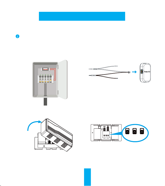
Power Kit Installation
•If you have the mechanical chime in your home, start from Step 1 here.
•If you have the electronic chime in your home, please refer to its manual for detailed
operations.
•If you do not have any chime, skip power kit installation and follow the Option B in page 5.
Insert one end of the wire harness the power kit.
1 Shut off the electricity at the breaker that
controls doorbell's circuit.
Remove the cover from your mechanical chime.
3
2
4 Re
move the existing chime wires in
the terminals named TRANS and FRONT.
REAR TRANSF RONT
REAR TRANS FRONT
2

5 Connect the wire harness to the chime's
terminals named TRANS and FRONT.
Insert the existing chime wire and the other
6
end of the wire harness into the wire
connector and twist it tightly. Repeat this
step with the other chime wire.
Wire Connector
Wiring Overview
REAR TRANS FRONT
REAR TRANS FRONT
DO NOT OIL
7. Mount the power kit to the side of the chime.
3
Chime Wire
Chime Wire
Chime Wire
8. Put back the chime cover.
Wire Harness

Doorbell Mounting
1 Shut off the electricity at the breaker that
controls doorbell's circuit.
(Optional) Paste the plate foam to the
2
mounting plate.
Use the plate foam when your wall is uneven.
Insert the mini-level into the mounting plate and
3
mark the drill points when its bubble stays in the middle.
Mini-Level
5
Remove the mini-level when drill points are marked.
4
4 Drill holes according to drill points
and insert anchors.
Anchor
Fix the mounting plate to the wall.
Mounting Screw

If power kit is installed, follow Option A; If not, follow Option B.
6
Option A Connect doorbell with your existing doorbell wires.
U-Shaped Wire
Fixing Screw
Option B Connect the fuse wire with your existing doorbell wire.
U-Shaped Wire
Fixing Screw
5

7 Fix the doorbell to the mounting plate by
inserting the doorbell screws.
Doorbell Screw
Doorbell is powered on when its indicator flashes blue quickly. If not, make sure your electricity
is off and check the wiring. If yes, proceed to doorbell setup.
Restore the electricity at the breaker.
8
Doorbell Setup
Add to Alula app.
9
- Add a camera to the Alula app
• Log in to your account using the Alula app.
• From the Alula app Camera screen, tap “+” on the upper-right hand corner to go to the
scan QR code interface.
- Scan the QR Code on the bottom of the camera.
- Enter the verification code located on the bottom of the camera.
- Follow the app wizard to finish Wi-Fi configuration.
If you want to change your camera's Wi-Fi, press and hold the reset button for 10s and repeat this part.
6

Put the faceplate back and insert two security screws into the bottom of the doorbell to secure the
10
faceplate.
Security Screw
Appendix
Basics
SD Card Management
Mounting Holes
LED Indicator
Blue Light
Red Light
micro SD
Card Slot
Reset Button
Hold for 5s to reset and
enter to AP mode.
Flashing Doorbell AP Mode is on.
Steady on Doorbell is working.
Flashing Fast Device Exception
Steady on Doorbell is powering on.
Terminals
If the memory card status displays as
Uninitialized, tap to initialize it.
7

This device complies with Part 15 of the FCC Rules. Operation is subject to the
following two conditions:
(1) This device may not cause harmful interference, and
(2) This device must accept any interference received, including interference that
may cause undesired operation.
Note: This product has been tested and found to comply with the limits for a Class
B digital device, pursuant to Part 15 of the FCC Rules. These limits are designed to
provide reasonable protection against harmful interference in a residential
installation. This product generates, uses, and can radiate radio frequency energy
and, if not installed and used in accordance with the instructions, may cause
harmful interference to radio communications. However, there is no guarantee that
interference will not occur in a particular installation. If this product does cause
harmful interference to radio or television reception, which can be determined by
turning the equipment off and on, the user is encouraged to try to correct the
interference by one or more of the following measures:
—Reorient or relocate the receiving antenna.
—Increase the separation between the equipment and receiver.
—Connect the equipment into an outlet on a circuit different from that to which the
receiver is connected.
—Consult the dealer or an experienced radio/TV technician for help.
Please take attention that changes or modification not expressly approved by the
party responsible for compliance could void the user’s authority to operate the
equipment.
This equipment complies with FCC/IC RSS-102 radiation exposure limits set forth
for an uncontrolled environment. This equipment should be installed and operated
with minimum distance 20cm between the radiator & your body.
This device complies with Industry Canada licence-exempt RSS standard(s).
Operation is subject to the following two conditions:
(1) this device may not cause interference, and
(2) this device must accept any interference, including interference that may cause
undesired operation of the device.
Le présent appareil est conforme aux CNR d'Industrie Canada applicables aux
appareils radioexempts de licence. L'exploitation est autorisée aux deux conditions
suivantes :
(1) l'appareil ne doit pas produire de brouillage, et
(2) l'utilisateur de l'appareil doit accepter tout brouillage radioélectrique subi,
même si le brouillage est susceptible d'en compromettre le fonctionnement.
Under Industry Canada regulations, this radio transmitter may only operate using an
antenna of a type and maximum (or lesser) gain approved for the transmitter by
Industry Canada. To reduce potential radio interference to other users, the antenna
type and its gain should be so chosen that the equivalent isotropically radiated power
(e.i.r.p.) is not more than that necessary for successful communication.

Conformément à la réglementation d'Industrie Canada, le présent émetteur radio peut
fonctionner avec une antenne d'un type et d'un gain maximal (ou inférieur) approuvé
pour l'émetteur par Industrie Canada. Dans le but de réduire les risques de
brouillage radioélectrique à l'intention des autres utilisateurs, il faut choisir le type
d'antenne et son gain de sorte que la puissance isotrope rayonnée équivalente (p.i.r.e.)
ne dépasse pas l'intensité nécessaire à l'établissement d'une communication
satisfaisante.
This equipment complies with FCC/IC RSS-102 radiation exposure limits set forth
for an uncontrolled environment. This equipment should be installed and operated
with minimum distance 20cm between the radiator & your body.
ce matériel est conforme aux limites de dose d'exposition aux rayonnements, FCC /
CNR-102 énoncée dans un autre environnement.cette eqipment devrait être installé
et exploité avec distance minimale de 20 entre le radiateur et votre corps.
The user manual for local area network devices shall contain instructions related to
the restrictions mentioned in the above sections, namely that:
(i) the device for operation in the band 5150-5250 MHz is only for indoor use to
reduce the potential for harmful interference to co-channel mobile satellite
systems;
(ii) the maximum antenna gain permitted for devices in the bands 5250-5350 MHz
and 5470-5725 MHz shall comply with the e.i.r.p. limit; and
(iii) the maximum antenna gain permitted for devices in the band 5725-5825 MHz
shall comply with the e.i.r.p. limits specified for point-to-point and non
point-to-point operation as appropriate.
(i)Les dispositifs fonctionnant dans la bande 5150-5250 MHz sont réservés
uniquement pour une utilisation à l'intérieur afin de réduire les risques de brouillage
préjudiciable aux systèmes de satellites mobiles utilisant les mêmes canaux.
(ii) le gain d'antenne maximal autorisé pour les appareils dans les bandes
5250-5350 MHz et 5470-5725 MHz doivent respecter le pire limiter; et
(iii) le gain d'antenne maximal autorisé pour les appareils dans la bande 5725-5825
MHz doivent respecter le pire limites spécifiées pour le point-à-point et l'exploitation
non point à point, le cas échéant.
Users should also be advised that high-power radars are allocated as primary users
(i.e. priority users) of the bands 5250-5350 MHz and 5650-5850 MHz and that these
radars could cause interference and/or damage to LE-LAN devices.
Les utilisateurs de radars de haute puissance sont désignés utilisateurs principaux
(c.-à-d., qu'ils ont la priorité) pour les bandes 5250-5350 MHz et 5650-5850 MHz et
que ces radars pourraient causer du brouillage et/ou des dommages aux dispositifs
LAN-EL.
 Loading...