


*11208917*
11208917
Thank you for buying this RESOL product.
Please read this manual carefully to get the best performance from this unit.
Please keep this manual carefully.
TT2
Thermostat controller with timer
Manual for the
specialised craftsman
Installation
Operation
Functions and options
Troubleshooting
www.resol.com
Manual
en

2
en
© 20160907_11208917_TT2.monen.indd
Target group
These instructions are exclusively addressed to authorised skilled personnel.
Only qualied electricians should carry out electrical works.
Initial installation must be effected by the system owner or qualied personnel
named by the system owner.
Description of symbols
WARNING!
Warnings are indicated with a warning triangle!
Î They contain information on how to avoid the danger
described.
Signal words describe the danger that may occur, when it is not avoided.
• WARNING means that injury, possibly life-threatening injury, can occur.
• ATTENTION means that damage to the appliance can occur.
Note:
Notes are indicated with an information symbol.
Î Arrows indicate instruction steps that should be carried out.
Disposal
• Dispose of the packaging in an environmentally sound manner.
• Dispose of old appliances in an environmentally sound manner. Upon request
we will take back your old appliances bought from us and guarantee an environmentally sound disposal of the devices.
Safety advice
Please pay attention to the following safety advice in order to avoid danger and
damage to people and property.
Instructions
Attention must be paid to the valid local standards, regulations and directives!
Information about the product
Proper usage
The thermostat controller is designed for use in standard solar thermal systems,
thermosiphon systems and heating systems with electric afterheating (electric im-
mersion heater) in compliance with the technical data specied in this manual.
Improper use excludes all liability claims.
CE Declaration of conformity
The product complies with the relevant directives and is therefore labelled with the CE mark. The Declaration of Conformity is available
upon request, please contact RESOL.
Note:
Strong electromagnetic elds can impair the function of the controller.
Î Make sure the controller as well as the system are not exposed to
strong electromagnetic elds.
Subject to technical change. Errors excepted.

3
en
Thermostat controller with timer
The TT2 Thermostat controller is equipped with 2 high-current relays to which an
electric immersion heater of up to 3.6 kW (230 V~) can be connected.
Thus, the TT2 manages the time and temperature control of the electric backup
heating for a DHW store. The rapid heat-up function makes for extra comfort. A
wireline remote control with an integrated LED (RESOL RCTT) enables a comfortable operation of the rapid heat-up function.
Contents
1 Overview ...............................................................................................4
2 Installation ............................................................................................5
2.1 Mounting .........................................................................................................................5
2.2 Electrical connection ....................................................................................................6
3 Operation and function .......................................................................7
3.1 Buttons ............................................................................................................................7
3.2 Operation........................................................................................................................7
4 System-Monitoring-Display .................................................................7
4.1 Menu structure ..............................................................................................................8
5 Display and adjustment channels ........................................................8
5.1 Controller time ..............................................................................................................8
5.2 Thermostat function .....................................................................................................9
5.3 Timer ............................................................................................................................. 10
5.4 Rapid heat-up .............................................................................................................. 10
5.5 Manual mode ............................................................................................................... 11
6 RCTT Remote control (accessory) ..................................................11

4
en
1 Overview
• Direct connection of an electric immersion heater up to
3.6 kW (230 V~)
• Time and temperature control of the electric backup heating
• Rapid heat-up function with optional remote control activation
• Intuitive operating concept
• Energy-efcient switch-mode power supply
• Thermosiphon systems
Technical data
Inputs: 1 Pt1000 temperature sensor, 1 input for RCTT Remote control
Outputs: 2 high-current relays for electric immersion heater
Switching capacity: 16 (3) A 240 V~ (high-current relay)
Power supply: 100 … 240 V~ (50 … 60 Hz)
Supply connection: type Y attachment
Standby: 0.44 W
Mode of operation: type 1.C action
Rated impulse voltage: 2.5 kV
Functions:
time-controlled thermostat function, DHW heating with rapid heat-up function
Housing: plastic, PC-ABS and PMMA
Mounting: wall mounting, also suitable for mounting into patch panels
Display: LC display, multi-functional combined display with pictograms, two 2-digit
text elds and two 4-digit 7-segment displays
Operation: 3 buttons at the front of the housing
Protection type: IP 20 / DIN EN 60529
Protection class: II
Ambient temperature: 0 … 50 °C
Degree of pollution: 2
Dimensions: 172 x110 x 46 mm
Weight: 330 g
110
30
62
172
46
130
Upper fastening
Lower fastening

5
en
2 Installation
2.1 Mounting
WARNING!
Electric shock!
Upon opening the housing, live parts are exposed!
Î Always disconnect the device from power supply
before opening the housing!
Note:
Strong electromagnetic elds can impair the function of the controller.
Î Make sure the controller as well as the system are not exposed to
strong electromagnetic elds.
The unit must only be located in dry interior rooms.
The controller must additionally be supplied from a double pole switch with con-
tact gap of at least 3 mm.
Please pay attention to separate routing of sensor cables and mains cables.
N
R1-N
R1-L
21
T1A
100 ... 240 V~
50-60 Hz
S1
L
IP 20
1011987
6
453
R1 | 16(3) A 240 V~
Temp. Sensor
Pt1000
RC TT
1
2
3
4
6
7
130 mm
Electrical connection see chap. 2.2
In order to mount the device to the wall, carry out the following steps:

6
en
2.2 Electrical connection
WARNING!
Electric shock!
Upon opening the housing, live parts are exposed!
Î Always disconnect the device from power supply be-
fore opening the housing!
WARNING!
ESD damage!
Electrostatic discharge can lead to damage to electronic components!
Î Take care to discharge properly before touching the
inside of the device!
Note:
The mains connection must be carried out with the common ground of
the building to which the pipework of the system is connected.
Note:
Connecting the device to the power supply must always be the last step
of the installation!
Note:
It must be possible to disconnect the device from the mains at any time.
Î Install the mains plug such that it is accessible at any time.
Î If this is not possible, install a switch that can be accessed.
Do not use the device if it is visibly damaged!
The power supply of the device must be 100 … 240 V~ (50 … 60 Hz). Attach exible
cables to the housing with the enclosed strain relief and the corresponding screws.
The mains connection is at the following terminals:
9 = Neutral conductor N
11 = Conductor L
7 = Grounding terminal ⌯
Connect the temperature sensor (S1) to the following terminals with either
polarity:
1 / 2 = Sensor 1 (e. g. store sensor)
Connect the RCTT Remote control (accessory) to the following terminals:
3 Switching input RCTT Remote control
4 GND RCTT Remote control
5 Signal LED output RCTT Remote control
The controller is equipped with 2 high-current relays (16 A) for connecting an
electric immersion heater (up to 3.6 kW at 230 V~ or up to 1.8 kW at 115 V~
respectively):
6 Grounding terminal ⌯
10 Conductor electric immersion heater
8 Neutral conductor electric immersion heater
S1
RC TT
100... 240
V~
N
R1-N
R1-L
10L11987
6
21453
R1 | 16(3) A 240 V~
T1A
100 ... 240 V~
50-60 Hz
Temp. Sensor
Pt1000
S1
RC TT
Made in Germany
TT2
IP 20

7
en
3 Operation and function
3.1 Buttons
Scrolling downwards / reducing
adjustment values (-)
Scrolling upwards / increasing
adjustment values (+)
Selection / adjustment mode / con rming
1
3
2
3.2 Operation
Accessing the adjustment mode
Adjustment mode
Changing a value
(Scrolling upwards / downwards)
Con rming a value &
to the next parameter
To the next channel
Selecting a channel
3 s
3 s
Note:
If the adjustment mode is active and if no button is pressed for 10 s, the
controller will automatically quit the adjustment mode.
4 System-Monitoring-Display
The System-Monitoring-Display consists of 2 blocks: channel display and tool bar.
Channel display
The channel display consists of 2 lines. In the 16-segment displays, parameter names
are displayed. In the 7-segment displays, values are displayed.
Tool bar
The additional symbols in the tool bar indicate the current system state.
Permanently
shown
Flashing Status indications
⓵
Backup heating active, relay 1 switched on
⓵ + ☛
Rapid heat-up active, relay 1 switched on
3 x ☛
Rapid heat-up not possible, because switch-off temperature
exceeded
⓵ + ☛ ⚠
Manual mode active, relay 1 switched on (ON)
☛ ⚠
Manual mode active, relay 1 switched off (OFF)
⚠ + ☍
Sensor fault
8
en
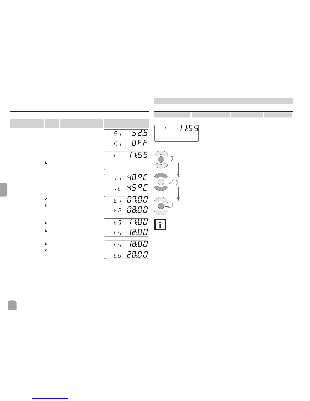
4.1 Menu structure
The menu is structured as follows:
Channel
Parameter
Description Display
Display channel 1
S1
Temperature sensor 1 / store
R1
Status relay / electric
immersion heater
Display channel 2
Current time
Adjustment channel 1
t1
Switch-on temperature
t2
Switch-off temperature
Adjustment channel 2
1
Time frame 1 switch-on time
2
Time frame 1 switch-off time
Adjustment channel 3
3
Time frame 2 switch-on time
4
Time frame 2 switch-off time
Adjustment channel 4
5
Time frame 3 switch-on time
6
Time frame 3 switch-off time
5 Display and adjustment channels
5.1 Controller time
Adjustment channel Description Adjustment range Factory setting
t Time 00:00 … 23:59
Indicates the current clock time.
Adjustment mode
Con rming a value &
to the next parameter
Adjusting the time
3 s
3 s
Note:
Adjust the current time so that the controller can function properly.

9
en
5.2 Thermostat function
Adjustment channel
Description Adjustment range Factory setting
T1
Switch-on temperature 0 … 90°C 40°C
T2
Switch-off temperature 5 … 95°C 45°C
The thermostat function is used for controlling the backup heating.
If the temperature at sensor S1 falls below the adjusted switch-on temperature T1,
backup heating will be switched on. If the temperature at sensor S1 reaches the
adjusted switch-off temperature T2, backup heating will be switched off.
In order to prevent the backup heating from being switched on and off too often,
the switch-on and switch-off temperatures T1 and T2 are blocked against each
other.
T1
25 30 35 40 45 50 55 60 65
T2
25 30 35 40 45 50 55 60 65
T1
T2
25 30 35 40 45 50 55 60 65
T1
T2
T1
25 30 35 40 45 50 55 60 65
T2
T1
25 30 35 40 45 50 55 60 65
T2
Automatic upward shift of T2, if T1 reaches
the limit (T2 - 5K)
If T2 decreases, it is blocked against
(T1 + 5K)
In order to avoid, but permit if necessary, long switch-on times of the backup heating, the switch-on and switch-off temperatures T1 and T2 are linked to each other.
T1
25 30 35 40 45 50 55 60 65
T2
25 30 35 40 45 50 55 60 65
T1
T2
25 30 35 40 45 50 55 60 65
T1
T2
T1
25 30 35 40 45 50 55 60 65
T2
25 30 35 40 45 50 55 60 65
T1
T2
Automatic downward shift of T2, if T1
reaches the limit (T2 - 15K)
Automatic downward shift of T2, only if it is
within (T2 - 15K) before the adjustment
T1
25 30 35 40 45 50 55 60 65
T2
25 30 35 40 45 50 55 60 65
T1
T2
T2 can be freely increased
Changing a value
(Scrolling upwards / downwards)
Con rming a value &
to the next parameter
To the next channel
3 s

10
en
5.3 Timer
Adjustment
channel
Description
Adjustment
range
Factory
setting
t1 Time frame 1 switch-on time 00:00 … 23:45 07:00
t2 Time frame 1 switch-off time 00:00 … 23:45 08:00
t3 Time frame 2 switch-on time 00:00 … 23:45 11:00
t4 Time frame 2 switch-off time 00:00 … 23:45 12:00
t5 Time frame 3 switch-on time 00:00 … 23:45 18:00
t6 Time frame 3 switch-off time 00:00 … 23:45 20:00
In order to block the thermostat function for a certain period, there are 3 time
frames. They can be adjusted by means of the parameters switch-on and switch-off
times (see table).
If the thermostat function is supposed to run from 06:00 a.m. to 09:00 a.m., adjust
t3 to 06:00 a.m. and t4 to 09:00 a.m. Outside these time frames the backup heating
is blocked and can be activated via the rapid heat-up function only.
If the switch-on and switch-off times of a time frame are set to an identical value,
the time frame will be inactive. If all time frames are set to 00:00, the thermostat
function is solely temperature dependent.
Changing a value
(Scrolling upwards / downwards)
Con rming a value &
to the next parameter
To the next channel
3 s
Note:
The time frames are not blocked against each other. If the values of 2 time
frames overlap, they will be considered as 1 common time frame.
5.4 Rapid heat-up
Rapid heat-up enables immediate heating of the store even outside the adjusted
time frames.
If rapid heat-up is activated, the controller will switch on the backup heating of
the store. Rapid heat-up of the store will stop, if the switch-off temperature T2 is
reached at sensor S1.
In order to activate the rapid heat-up, scroll to the rst display channel, press
and hold down button 1 for 3 s. It is also possible to press the button of the
RCTT Remote control (accessory) instead.
3 s
In order to deactivate the rapid heat-up, press and hold down the controller button 1 again for 3 s. It is also possible to press the button of the RCTT Remote
control again instead.
Note:
If the temperature at sensor S1 exceeds the adjusted switch-off temperature T2 while rapid heat-up is being activated, rapid heat-up will be
blocked. The controller will give feedback, see page 7 and page 11.
Note:
If the temperature at sensor S1 does not reach the switch-off temperature within 120 min after the rapid heat-up has started, the controller
will switch off the backup heating of the store for safety reasons.

11
en
5.5 Manual mode
Adjustment channel Description Adjustment range Factory setting
R1 Manual mode On, Auto, Off Auto
For control and service work, the operating mode of the relay can be manually
adjusted. For this purpose, select the adjustment channel R1 in which the following
adjustments can be made:
Adjustment mode of the manual mode
OFF : Relay off ⚠ ( ashing) + ☛
Auto : Relay in automatic operation
ON : Relay on ⚠ ( ashing) + ☛ + ⓵
In order to access the adjustment channel R1 for adjusting the manual mode, scroll
to the rst display channel, press and hold down button 3 for 3 s.
3 s
WARNING!
Electric shock!
Upon opening the housing, live parts are exposed!
Î Always disconnect the device from power supply be-
fore opening the housing!
Note:
Danger of high currents (16 A), if the manual mode is set to ON.
Note:
If the manual mode is set to ON, the controller will switch the manual
mode back to Auto after 30 s for safety reasons.
6 RCTT Remote control (accessory)
The RCTT Remote control enables rapid heat-up activation via the button without having to access the controller menu. It is connected to the controller with a
3-wire cable (see page 6).
If the button of the RCTT is pressed, rapid heat-up will be activated on the controller. If rapid heat-up is already active, it will be deactivated.
If rapid heat-up is active on the controller, the LED of the RCTT will be permanently red.
If rapid heat-up is not possible, because the temperature at sensor S1 has exceeded
the switch-off temperature T2, the LED of the RCTT will brie y ash 3 times.
In the case of a sensor fault, the LED of the RCTT will be ashing continuously.
The RCTT Remote control has to be connected to the controller according to the
installation instructions mentioned in the RCTT Remote control manual.

Distributed by:
RESOL – Elektronische Regelungen GmbH
Heiskampstraße 10
45527 Hattingen / Germany
Tel.: +49 (0) 23 24 / 96 48 - 0
Fax: +49 (0) 23 24 / 96 48 - 755
www.resol.com
info@resol.com
Important note
The texts and drawings in this manual are correct to the best of our knowledge. As
faults can never be excluded, please note:
Your own calculations and plans, under consideration of the current standards and
directions should only be basis for your projects. We do not offer a guarantee for
the completeness of the drawings and texts of this manual - they only represent
some examples. They can only be used at your own risk. No liability is assumed for
incorrect, incomplete or false information and / or the resulting damages.
Note
The design and the specications can be changed without notice.
The illustrations may differ from the original product.
Imprint
This mounting- and operation manual including all parts is copyrighted. Another
use outside the copyright requires the approval of RESOL – Elektronische Rege-
lungen GmbH. This especially applies for copies, translations, micro lms and the
storage into electronic systems.
© RESOL – Elektronische Regelungen GmbH
 Loading...