


EM Extension module
Mounting
Connection
Operation
*48006400*
48006400
Thank you for buying this RESOL product.
Please read this manual carefully to get the best performance from this unit. Please keep this
manual carefully.
en
Manual
www.resol.com

Safety advice
Please pay attention to the following safety advice
in order to avoid danger and damage to people and
property.
Instructions
Attention must be paid to the valid local standards,
regulations and directives!
Target group
These instructions are exclusively addressed to authorised skilled personnel.
Only qualified electricians should carry out electrical
works.
Description of symbols
WARNING!
Warnings are indicated with a warning triangle!
Î They contain information
on how to avoid the danger
described.
Signal words describe the danger that may occur,
when it is not avoided.
• WARNING means that injury, possibly life-threat-
ening injury, can occur.
• ATTENTION means that damage to the appli-
ance can occur.
Î Arrows indicate instruction steps that should be
carried out.
Information about the product
Proper usage
The extension module is designed for use in combination with a controller equipped with a VBus
®
data
interface in compliance with the technical data specified in this manual.
Improper use excludes all liability claims.
CE-Declaration of conformity
The product complies with the relevant directives and is therefore labelled with the
CE mark. The Declaration of Conformity
is available upon request, please contact
RESOL.
Note
Strong electromagnetic fields can impair the
function of the device.
Î Make sure the device as well as the sys-
tem are not exposed to strong electromagnetic fields.
Disposal
• Dispose of the packaging in an environmentally
sound manner.
• Dispose of old appliances in an environmentally
sound manner. Upon request we will take back
your old appliances bought from us and guarantee
an environmentally sound disposal of the devices.
Subject to technical change. Errors excepted.
Contents
1 Overview ................................................... 3
2 Installation ................................................4
2.1 Mounting .................................................................. 4
2.2 Electrical connection ............................................. 5
2.3 Data communication / Bus ................................... 5
3 Operation .................................................. 6
3.1 Buttons ..................................................................... 6
3.2 Selecting channels and adjusting values ............. 6
3.3 Slide switch .............................................................. 6
3.4 Flashing codes and warning symbols .................. 6
4 Initial commissioning ............................... 7
5 Menu system ............................................. 7
5.1 Channel overview .................................................. 7
5.2 Display channels ...................................................... 8
5.3 Adjustment channels .............................................8
6 Troubleshooting ........................................ 9
7 Accessories .............................................10
7.1 Sensors ................................................................... 10
Note
Notes are indicated with an information
symbol.
2
© 20140620_48006400_EM.monen.indd

1 Overview
• Extension of the controller by
6 sensor inputs and 5 relay outputs
• 7-segment LC display
• Function control
• Slide switch 0 Auto I
• RESOL VBus
®
interface
en
Technical data:
Inputs: 6 Pt1000, Pt500 or KTY temperature sensors
Outputs:
4 semiconductor realys and 1 potential-free relay
Switching capacity:
1 (1) A 240 V~ (semiconductor relay)
4 (1) A 24 V
/ 240 V~ (potential-free relay)
Total switching capacity: 4 A 240 V~
Power supply: 100 ... 240 V~ (50 ... 60 Hz)
Supply connection: type Y attachment
Power consumption: < 1 W (standby)
Mode of operation: type 1.B.C.Y action
Rated impulse voltage: 2.5 kV
Data interface: RESOL VBus
®
Housing: plastic, PC-ABS and PMMA
Mounting: wall mounting
Indication / Display: LC display, 7-segment display
Operation: 3 push buttons and 1 slide switch at the
front of the housing
Ingress protection: IP 20 / EN 60529
Protection class: II
Ambient temperature: 0 ... 40 °C
Pollution degree: 2
Dimensions: 144 × 208 × 43 mm
3

2 Installation
WARNING!
2.1 Mounting
The device must only be located in dry interior
rooms. It is not suitable for installation in hazardous
locations and should be protected against electromagnetic fields.
The device must additionally be supplied from a double pole switch with contact gap of at least 3 mm.
Please pay attention to separate routing of sensor cables and mains cables.
en
Î Unscrew the crosshead screw from the cover
and remove the cover.
Î Mark the upper fastening point on the wall. Drill
and fasten the enclosed wall plug and screw leaving the head protruding.
Î Hang the housing from the upper fastening point
and mark the lower fastening points (centres
180 mm).
Î Drill and insert the lower wall plug.
Î Fasten the housing to the wall with the lower fas-
tening screw and tighten.
Electric shock!
Upon opening the housing, live parts
are exposed!
Î Always disconnect the
device from power supply
before opening the housing!
crosshead
screw
slide switch
push buttons
cover
180
180
208
lower fastening
upper fastening
12.5
43.3
16.75
100
144
cable conduits with strain
relief
4

2.2 Electrical connection
ATTENTION!
ESD damage!
Electrostatic discharge can lead to
damage to electronic components!
Î Take care to discharge
properly before touching
the inside of the device!
Note
Connecting the device to the power supply
must always be the last step of the installation!
The device is equipped with 4 semiconductor relays
and 1 potential-free relay to which loads such as
pumps, valves, etc. can be connected:
Depending on the product version, the mains cable and
the sensor cables are already connected to the device.
If that is not the case, please proceed as follows:
Connect the temperature sensors (S1 to S6) to
the corresponding terminals with either polarity:
1/2 sensor 1
3/4 sensor 2
5/6 sensor 3
7/8 sensor 4
9/10 sensor 5
11/12 sensor 6
Connect the RESOL VBus® to the terminals marked
“VBus” with either polarity:
13/14 VBus terminals
Potential-free relay:
15 conductor R5-A (normally open contact)
16 conductor R5-M (normally closed contact)
17 … 21
ground terminal
Semiconductor relays:
22 neutral conductor R4
23 normally open contact R4
24 neutral conductor R3
25 normally open contact R3
26 neutral conductor R2
27 normally open contact R2
28 neutral conductor R1
29 normally open contact R1
17 … 21 ground terminal
Connect the mains cable to the following terminals:
30 neutral conductor N
31 conductor L
17 … 21
ground terminal
Attach flexible cables to the housing with the enclosed strain relief and the corresponding screws.
The device is supplied with power via the mains
cable. The mains voltage must be 100 … 240 V~
(50 … 60 Hz).
EM
Made in Germany
S1 S2 S3
12
3456
sensor terminals
S4
78S611 12
S5
910
IP 20
VBus
13 14
VBus
15 16
®
potential-free relay
2.3 Data communication / Bus
The device is equipped with a RESOL VBus
data communication with the controller. Carry out
the connection at the two terminals marked “VBus”
(any polarity).
T4A
V100 ... 240 ~
50-60 Hz
R1N
R2N
2928
2726
R5-A
R5-M
1817
212019
ground common
terminal block
R1-R4
1 (1) A (100 ...240) V~
4 (1) A (100 ...240) V~
R5
R4N
2322
load terminals
R3N
2524
mains terminals
®
for
en
LN
3130
5
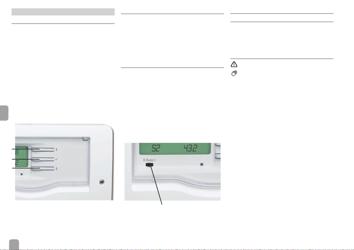
3 Operation
3.1 Buttons
The device is operated via the 3 buttons next to the
display which have the following functions:
Button 1: scrolling backwards through the menu or
increasing adjustment values
Button 2: scrolling forwards through the menu or
decreasing adjustment values
Button 3: changing to the adjustment mode or
confirming
If an adjustment value is shown on the display, SEt is
displayed. Briefly press button 3 in order to access the
adjustment mode
en
1
3
2
3.2 Selecting channels and adjusting values
Î Select the requested channel using buttons 1 and
2.
Î Briefly press button 3, SEt flashes (adjustment
mode)
Î Adjust the value by pressing buttons 1 and 2
Î Briefly press button 3
SEt permanently appears, the adjusted value is stored.
3.3 Slide switch
By means of the slide switch, an adjustable selection of
relays (see channel MM, page 8) can be switched
on (I) or off (0) manually. When the slide switch is set
to Auto, the adjustments of the channels M1 … M5
are valid.
Manually OFF = 0 (left)
Manually On = I (right)
Automatic mode = Auto (mid position) – adjustments made in M1 … M5
3.4 Flashing codes and warning symbols
3.4.1 LED flashing codes
green: everything OK
green flashing: manual mode
red flashing: VBus® cable broken or controller
not detected
3.4.2 Warning symbols
= no VBus® communication
= manual mode (see chap. 3.3):
flashing: slide switch in position I
permanent: slide switch in position 0
Slide switch
6

4 Initial commissioning
For initial commissioning of the EM, proceed as follows:
1. Connect the VBus® cable
2. Establish mains connection
3. Adjust the sub-address (SA)
4. Register the module in the controller (see controller manual)
Note
To register the module in the controller, use
the same number that has been selected as
sub-address! Example:
If SA = 1, register the EM as module 1 in
the controller.
5 Menu system
5.1 Channel overview
Channel Description Page
S1 D Value at sensor 1 8
S2 D Value at sensor 2 8
S3 D Value at sensor 3 8
S4 D Value at sensor 4 8
S5 D Value at sensor 5 8
S6 D Value at sensor 6 8
R1 D Speed relay 1 8
R2 D Speed relay 2 8
R3 D Speed relay 3 8
R4 D Speed relay 4 8
R5 D Status relay 5* 8
VC D Version compatibility 8
EC D Error code 8
M1 P Manual mode R1 8
M2 P Manual mode R2 8
M3 P Manual mode R3 8
M4 P Manual mode R4 8
M5 P Manual mode R5 8
MM P Slide switch manual mode 8
T1 P Sensor type sensor 1 8
T2 P Sensor type sensor 2 8
T3 P Sensor type sensor 3 8
T4 P Sensor type sensor 4 8
T5 P Sensor type sensor 5 8
T6 P Sensor type sensor 6 8
SA P Sub-address 8
PG D Program 8
VN D Version number 8
D = Display channel
P = Adjustment parameter
en
* R5 is a potential-free relay not suitable for speed
control. Therefore, its status is indicated with 0 %
or 100 % respectively.
7

5.2 Display channels
Error code display
EC
Error code
Display range: 0, 2
0 = OK
2 = Bus error (there has been no bus communication for approx. 1 min)
Version compatibility display
VC
Version compatibility
Display range: 0, 4
This channel indicates if the controller connected has
been recognised by the module.
If 0 is indicated, the controller has not been recognised or the bus communication is faulty.
en
If 4 is indicated, the extension module has recognised
the controller and is functioning normally.
Display of sensor temperatures
S1 … S6
Display of measured values
Display range: -40 … +260 °C
Only if a sensor is connected to the corresponding
terminal, will a value be displayed.
In the case of a line break or if no sensor is connected,
9999 will be displayed.
In the case of a short circuit, 0 will be displayed.
Display of speed
R1 … R5
Display of speed / status
Display range: 0 … 100 %
These channels indicate the current speed values of
the relays. R5 is a potential-free relay not suitable for
speed control. Therefore, its status is indicated with
0 % or 100 % respectively.
Display of the software version
PG
This channel indicates the version number of the
firmware.
Display of the version number
VN
This channel indicates the version number of the
hardware.
5.3 Adjustment channels
Manual mode
M1 … M5
Adjustment range: OFF, Auto, On
Factory setting: Auto
In the channels M1 to M5, the corresponding relays
can be switched on or off, or set to automatic mode
manually.
Manual mode
MM
Adjustment range: 0 … 5
Factory setting: 0
The adjustment in this channel determines which relays are switched on when the slide switch below the
display is set to I.
0 = Relay 1 on, all others off
1 = Relays 1 and 2 on, all others off
2 = Relays 1 and 5 on, all others off
3 = Relays 1, 2 and 5 on, all others off
4 = Relays 1 and 4 on, all others off
5 = Relays 1, 4 and 5 on, all others off
Selecting the sensor type
T1 … T6
Adjustment range: 0 … 4
Factory setting: 0
In this menu, a sensor type can be selected for each
sensor input. The following adjustments are available:
0 = Resistance (the measured resistance will be displayed independent of the sensor type connected)
1 = Pt1000
2 = KTY
3 = PT500
4 = RTA (remote control)
Note
The adjustments made in the channels
T1 … T6 only determine the display of the
measured values in the channels S1 … S6 of
the extension module.
Î Adjust the sensor type in the controller
connected as well!
Allocating a sub-address
SA
Adjustment range: 1 … 15
Factory setting: 1
In this channel, a sub-address can be allocated to the
module. The in- and outputs of the module will be
displayed with the sub-address number in the controller connected.
Note
To register the module in the controller, use
the same number that has been selected as
sub-address! Example:
If SA = 1, register the EM as module 1 in
the controller.
8

6 Troubleshooting
If a malfunction occurs, the display symbols will indicate an error code (see chap. 3.4.2).
WARNING!
The device is protected by a fuse. The fuse holder
(which also holds the spare fuse) becomes accessible
when the cover is removed. To replace the fuse, pull
the fuse holder from the base.
Electric shock!
Upon opening the housing, live
parts are exposed!
Î Always disconnect the
device from power supply
before opening the housing!
fuse holder
In the senor temperature display channels, line breaks
or short circuits of the sensor cable will be displayed.
Error messages for sensor faults are only indicated in
the controller connected.
Disconnected temperature sensors can be checked
with an ohmmeter. Please check the resistance values
correspond with the table.
°C °F
-10 14 481 961 1499
-5 23 490 980 1565
0 32 500 1000 1633
5 41 510 1019 1702
10 50 520 1039 1774
15 59 529 1058 1847
20 68 539 1078 1922
25 77 549 1097 2000
30 86 559 1117 2079
35 95 568 1136 2159
40 104 578 1155 2242
45 113 588 1175 2327
50 122 597 1194 2413
55 131 607 1213 2502
60 140 616 1232 2592
65 149 626 1252 2684
70 158 636 1271 2778
75 167 645 1290 2874
80 176 655 1309 2971
85 185 664 1328 3071
90 194 634 1347 3172
95 203 683 1366 3275
100 212 693 1385 3380
105 221 702 1404 3484
110 230 712 1423 3590
115 239 721 1442 3695
Ω
Pt500ΩPt1000ΩKTY
Operating control lamp is permanently off.
If the control lamp is permanently off, check the
power supply of the device. Is it disconnected?
no
The fuse of the device
could be blown. The
fuse holder (which
holds the spare fuse)
becomes accessible
when the cover is
removed.The fuse can
then be replaced.
and reconnect it.
yes
Check the supply line
en
9

7 Accessories
7.1 Sensors
Sensors
The product range includes high-precision platinum
temperature sensors, flatscrew sensors, outdoor temperature sensors, indoor temperature sensors, cylindrical clip-on sensors, also as complete sensors with
immersion sleeve.
en
Overvoltage protection device
In order to avoid overvoltage damage at collector
sensors (e.g. caused by local lightning storms), we
recommend installting the overvoltage protection
RESOL SP10.
RESOL SP10 Article no.: 180 110 70
10

Notes
en
11

Distributed by:
RESOL - Elektronische Regelungen GmbH
Heiskampstraße 10
45527 Hattingen / Germany
Tel.: +49 (0) 23 24 / 96 48 - 0
Fax: +49 (0) 23 24 / 96 48 - 755
www.resol.com
info@resol.com
Important note
The texts and drawings in this manual are correct to the best of our knowledge. As
faults can never be excluded, please note:
Your own calculations and plans, under consideration of the current standards and
directions should only be basis for your projects. We do not offer a guarantee for
the completeness of the drawings and texts of this manual - they only represent
some examples. They can only be used at your own risk. No liability is assumed for
incorrect, incomplete or false information and / or the resulting damages.
Note
The design and the specifications can be changed without notice.
The illustrations may differ from the original product.
Imprint
This mounting- and operation manual including all parts is copyrighted. Another
use outside the copyright requires the approval of RESOL – Elektronische Re-
gelungen GmbH. This especially applies for copies, translations, micro films and
the storage into electronic systems.
© RESOL – Elektronische Regelungen GmbH
 Loading...