


*11213305*
11213305
Thank you for buying this RESOL product.
Please read this manual carefully to get the best performance from this unit. Please keep this
manual safe.
DeltaTherm
®
HC MAX
www.resol.com
Manual
en
Heating controller
Manual for the
specialised craftsman
Installation
Operation
Functions and options
Troubleshooting
Beginning with rmware version 2.04
The Internet portal for easy and secure access to
your system data – www.vbus.net

2
en
© 20180528_11213305_DeltaTherm_HC_MAX_monen.indd
Safety advice
Please pay attention to the following safety advice in order to avoid danger and
damage to people and property.
Instructions
Attention must be paid to the valid local standards, regulations and directives!
Information about the product
Proper usage
The controller is designed for use in heating systems in compliance with the tech-
nical data specied in this manual.
Improper use excludes all liability claims.
EU declaration of conformity
The product complies with the relevant directives and is therefore labelled with the CE mark. The Declaration of Conformity is available upon
request, please contact the manufacturer.
Note
Strong electromagnetic elds can impair the function of the controller.
Î Make sure the controller as well as the system are not exposed to
strong electromagnetic elds.
Target group
These instructions are exclusively addressed to authorised skilled personnel.
Only qualied electricians are allowed carry out electrical works.
Initial commissioning must be effected by the system installer or qualied personnel
named by the system installer.
Subject to technical change. Errors excepted.
Description of symbols
WARNING!
Warnings are indicated with a warning triangle!
Î They contain information on how to avoid the danger
described.
Signal words describe the danger that may occur, when it is not avoided.
• WARNING means that injury, possibly life-threatening injury, can occur.
• ATTENTION means that damage to the appliance can occur.
Note
Notes are indicated with an information symbol.
Î Arrows indicate instruction steps that should be carried out.
Disposal
• Dispose of the packaging in an environmentally sound manner.
• At the end of its working life, the product must not be disposed of as urban waste.
Old appliances must be disposed of by an authorised body in an environmentally
sound manner. Upon request we will take back your old appliances bought from
us and guarantee an environmentally sound disposal of the devices.

3
en
DeltaTherm® HC MAX
The DeltaTherm
®
HC MAX can control up to 4 weather-compensated heating
circuits, the DHW loading and the backup heating demand for both. Additional
DHW functions such as circulation or thermal disinfection, and the efcient imple-
mentation of further heat sources are possible.
With extension modules, further heating circuits can be controlled. Due to the
exible application and extension possibilities, the heating controller is also ideal for
larger objects such as apartment houses, residential homes and industrial buildings.
Contents
1 Overview ............................................................................................... 4
1.1 Optional functions ........................................................................................................5
2 Installation ............................................................................................ 5
2.1 Mounting ......................................................................................................................... 5
2.2 Electrical connection .................................................................................................... 7
2.3 Data communication / Bus .......................................................................................... 8
2.4 SD card slot .................................................................................................................... 8
3 Step-by-step parameterisation ........................................................... 9
4 Operation and function ..................................................................... 10
4.1 Buttons ..........................................................................................................................10
4.2 Selecting menu points and adjusting values .......................................................... 10
4.3 Adjusting the timer ....................................................................................................12
4.4 Adjusting optional functions .....................................................................................14
4.5 Output selection submenu ................................................................ 16
5 Commissioning ................................................................................... 19
5.1 Schemes with basic settings ......................................................................................21
6 Main menu .......................................................................................... 31
6.1 Menu structure ............................................................................................................ 32
7 Status ................................................................................................... 33
7.1 Measured / Balance values .........................................................................................33
7.2 Heating ...........................................................................................................................33
7.3 Arrangement ................................................................................................................ 33
7.4 HQM ..............................................................................................................................33
7.5 Messages ........................................................................................................................ 34
7.6 Home screen ................................................................................................................ 34
8 Heating ................................................................................................ 34
8.1 Shared relays .................................................................................................................34
8.2 Heating circuits ............................................................................................................ 36
8.3 Optional functions ......................................................................................................44
8.4 Screed drying ................................................................................................................ 47
9 Arrangement ...................................................................................... 49
9.1 Optional functions ......................................................................................................49
10 HQM .................................................................................................... 58
11 Basic settings ...................................................................................... 59
12 SD card ................................................................................................ 60
13 Manual mode ...................................................................................... 61
14 User code ............................................................................................ 61
15 Inputs / Modules ................................................................................... 62
15.1 Modules ......................................................................................................................... 62
15.2 Inputs ..............................................................................................................................62
16 Troubleshooting .................................................................................. 64
17 Accessories ......................................................................................... 66
18 Index .................................................................................................... 68

4
en
1 Overview
• Up to 5 extension modules via RESOL VBus® connectable (45 sensors
and 39 relays in total), up to 7 weather-compensated heating circuits
• 2 inputs for digital Grundfos Direct Sensors™
• 2 inputs for analogue Grundfos Direct Sensors™
• Screed drying function
• Data logging, storing, easy transfer of controller adjustments pre-
paredandrmwareupdatesviaSDcard
• Cooling over the heating circuit with condensation detection by
means of a dew point switch
• Modulating heating control with 0-10 V boiler control
• Weather-compensatedcontrolwithroominuenceordemand-based
room control with up to 5 room temperature sensors HC per heating
circuit
• Remote access with a room control unit or the VBus
®
Touch HC App
Technical data
Inputs: 12 Pt1000, Pt500 or KTY temperature sensor inputs (can optionally be
used for remote controls, operating mode switches or potential-free switches),
3 impulse inputs for V40 owmeters (can optionally be used for Pt1000, Pt500 or
KTY temperature sensors, remote controls, operating mode switches or potential-free switches), 1 input for a FlowRotor, 1 CS10 solar cell, 4 Grundfos Direct
Sensors
TM
(2 x analogue, 2 x digital)
Outputs: 14 relays, 13 of them semiconductor relays for speed control,
1 potential-free relay, 4 PWM outputs (switchable to 0-10 V)
PWM frequency: 512 Hz
PWM voltage: 10.5 V
Switching capacity:
1 (1) A 240 V~ (semiconductor relay)
4 (2) A 24 V⎓ / 240 V~ (potential-free relay)
Total switching capacity: 6.3 A 240 V~
Power supply: 100 … 240 V~ (50 … 60 Hz)
Supply connection: type Y attachment
Standby: 0.83 W
Temperature controls class: VIII
Energyefciencycontribution: 5 %
Mode of operation: type 1.B.C.Y action
Rated impulse voltage: 2.5 kV
Data interface: RESOL VBus
®
, SD card slot
VBus
®
current supply: 35 mA
Functions: screed drying, weather-compensated heating circuit control, backup
heating, DHW heating with priority logic, circulation, thermal disinfection, heat quantity measurement, optional functions such as solid fuel boiler, return preheating, etc.
Housing: plastic, PC-ABS and PMMA
Mounting: wall mounting, also suitable for mounting into patch panels
Indication / Display: full graphic display
Operation: 7 buttons
Protection type: IP 20 / EN 60529
Protection class: I
Ambient temperature: 0 … 40 °C
Degree of pollution: 2
Dimensions: 253 × 200 × 47 mm

5
en
1.1 Optional functions
Heating
Thermal disinfection
DHW heating
DHW preheating
2 Installation
2.1 Mounting
WARNING!
Electric shock!
Upon opening the housing, live parts are exposed!
Î Always disconnect the device from power supply be-
fore opening the housing!
Note
Strong electromagnetic elds can impair the function of the device.
Î Make sure the device as well as the system are not exposed to strong
electromagnetic elds.
The unit must only be located in dry interior rooms.
The controller must additionally be supplied from a double pole switch with contact
gap of at least 3 mm.
Please pay attention to separate routing of sensor cables and mains cables.
In order to mount the device to the wall, carry out the following steps:
Î Unscrew the crosshead screw from the cover and remove it along with the
cover from the housing.
Î Mark the upper fastening point on the wall. Drill and fasten the enclosed wall
plug and screw leaving the head protruding.
Î Hang the housing from the upper fastening point and mark the lower fastening
points (centres 233 mm).
Î Insert lower wall plugs.
Î Fasten the housing to the wall with the lower fastening screws and tighten.
Î Carry out the electrical wiring in accordance with the terminal allocation (see
page 7).
Î Put the cover on the housing.
Î Attach with the crosshead screw.
Arrangement
Parallel relay
Mixer
Zone loading
Error relay
Heat exchange
Solid fuel boiler
Circulation
Return preheating
Function block
Irradiation switch
Return mixing function
253
200
47

6
en
1
2
4
3
5
6
Chap. 2.2
7
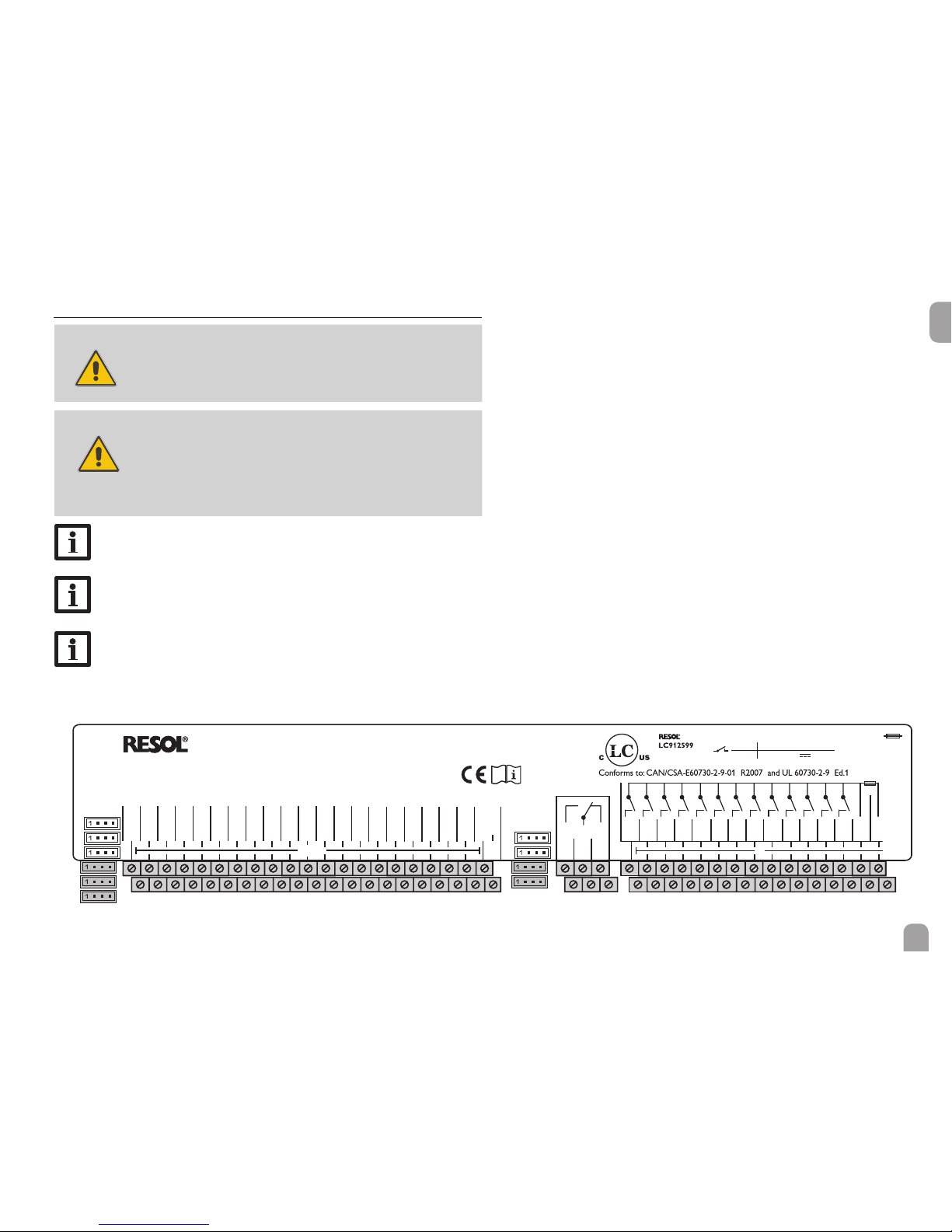
en
DeltaTherm® HC MAX
Made in Germany
S1
FR1
Ga2
Ga1
IP 20
S2S3S4S5S6S7S8S9S10
S11
S12
ABC
D
R13
R12
T6,3A
100 ... 240 V~
50-60 Hz
R11
R10R9R8R7R6
R5NR4R3R2
R1
L' L
CS10
R14-A
R14-M
R14-R
PWM
PWM
PWM
PWM
0-10V
0-10V
0-10V
0-10V
VBus
Gd2
Gd1
VBus
GND
GND
S13/ IMP1
S14/ IMP2
S15/ IMP3
R1-R13 1 (1) A 240 V~
4 (2) A 24 V /240 V~R14
DeltaSol® MX
2.2 Electrical connection
WARNING!
Electric shock!
Upon opening the housing, live parts are exposed!
Î Always disconnect the device from power supply
before opening the housing!
ATTENTION!
ESD damage!
Electrostatic discharge can lead to damage to electronic com-
ponents!
Î Take care to discharge properly before touching
the inside of the device! To do so, touch a grounded
surface such as a radiator or tap!
Note
Connecting the device to the power supply must always be the last step
of the installation!
Note
The pump speed must be set to 100 % when auxiliary relays or valves
are connected.
Note
It must be possible to disconnect the device from the mains at any time.
Î Install the mains plug so that it is accessible at any time.
Î If this is not possible, install a switch that can be accessed.
Do not use the device if it is visibly damaged!
The controller is equipped with 14 relays in total to which loads such as pumps,
valves, etc. can be connected:
Relays 1 ... 13 are semiconductor relays, designed for pump speed control:
Conductor R1 … R13
Neutral conductor N (common terminal block)
Protective earth conductor
⏚ (common terminal block)
Relay 14 is a potential-free relay:
R14-A = normally open contact
R14-M = centre contact
R14-R = normally closed contact
Depending on the product version, mains cables and sensor cables are already connected to the device. If that is not the case, please proceed as follows:
The temperature sensors (S1 to S12) have to be connected to the terminals S1
to S12 and GND (either polarity).

8
en
2.3 Data communication / Bus
The controller is equipped with the RESOL VBus
®
for data transfer and energy
supply to external modules. The connection is to be carried out at the terminals
marked VBus (any polarity).
One or more RESOL VBus
®
modules can be connected via this data bus, such as:
• RESOL DL2 / DL3 Datalogger
• RESOL KM2 Communication module
Furthermore, the controller can be connected to a PC or integrated into a network
via the RESOL VBus
®
/USB or VBus® /LAN interface adapter (not included). Differ-
ent solutions for visualisation and remote parameterisation are available on the
website www.resol.com. On the website, rmware updates are also available.
Note
During remote parameterisation, the symbol will be displayed, the con-
troller will not carry out any control function.
Note
For more information about accessories, see page 66.
2.4 SD card slot
The controller is equipped with an SD card slot.
With an SD card, the following functions can be carried out:
• Store measurement and balance values onto the SD card. After the transfer to a
computer, the values can be opened and visualised, e. g. in a spreadsheet.
• Prepare adjustments and parameterisations on a computer and transfer them via
the SD card.
• Store adjustments and parameterisations on the SD card and, if necessary, retrieve them from there.
• Download rmware updates from the Internet and install them on the controller.
Note
For more information about using an SD card, see page 60.
The V40 owmeters can be connected to the terminals S13 / IMP1 to S15 / IMP3
and GND (either polarity).
Connect the irradiation sensor CS10 to the terminals CS10 and GND with cor-
rect polarity. To do so, connect the cable marked GND to the GND common terminal block, the cable marked CS to the terminal marked CS10.
The terminals marked PWM / 0-10 V are control outputs for high-efciency pumps.
Note
When Grundfos Direct Sensors
TM
are used, connect the sensor ground
common terminal block to PE.
Connect the analogue Grundfos Direct Sensors™ to the Ga1 and Ga2 inputs.
Connect the digital Grundfos Direct Sensors™ to the Gd1 and Gd2 inputs.
Connect the FlowRotor to the FR1 input. (The FlowRotor is not available in the
RESOL portfolio)
The controller is supplied with power via a mains cable. The power supply of the
device must be 100 … 240 V~ (50 … 60 Hz).
Connect the mains cable to the following terminals:
Neutral conductor N
Conductor L
WARNING!
Electric shock!
L' is a fused contact permanently carrying voltage.
Î Always disconnect the device from power supply
before opening the housing!
Conductor L' (L' is not connected with the mains cable. L'is a fused contact
permanently carrying voltage)
Protective earth conductor ⏚ (common terminal block)
Note
For more details about the commissioning procedure see page 9.

9
en
3 Step-by-step parameterisation
The DeltaTherm® HC MAX is a controller that offers a broad variety of func-
tions to the user. At the same time, the user has a lot of freedom in congurating
them. Therefore, to set up a complex system, careful planning is required. We recommend drawing a sketch of the system rst.
If planning, hydraulic construction and electrical connection have all been carried
out successfully, proceed as follows:
1. Running the commissioning menu
After the commissioning menu has been nished (see page 19), further adjustments can be made. The commissioning menu can be repeated any time by means
of a reset (see page 59). Additional adjustments will be deleted.
For further information about the commissioning menu see page page 19.
2. Registering sensors
If owmeters, ow switches, Grundfos Direct Sensors™, a FlowRotor, room control units, remote controls, switches and/or external extension modules are connected, these have to be registered in the Inputs / Modules menu.
For further information about the registration of modules and sensors see page
62.
3. Adjusting heating circuits and activating optional heating functions
If one or more heating circuits are to be controlled, heating circuits can be activated
and adjusted.
For the heating part of the arrangement, up to 16 optional functions can be selected,
activated and adjusted.
To heating circuits and optional functions which require one or more relays, the
corresponding number of free relays can be allocated. The controller always sug-
gests the numerically smallest relay available.
Sensors can be allocated to more than one function.
For further information about heating circuits and optional heating functions see
page 36.
4. Activating optional arrangement functions
Up to 16 optional functions can be selected, activated and adjusted in the arrangement part.
Relays available can be allocated to optional functions which require a relay. The
controller always suggests the numerically smallest relay available.
Sensors can be allocated to more than one function.
For further information about the optional arrangement functions see page 49.

10
en
4 Operation and function
4.1 Buttons
The controller is operated via the 7 buttons next to the display. They have the
following functions:
Button ❶ - scrolling upwards
Button ❸ - scrolling downwards
Button ❷ - increasing adjustment values
Button ❹ - reducing adjustment values
Button ➄ - conrming
Button ➅ - entering the status menu / chimney sweeper mode
(system-dependent)
Button ➆ - escape button for changing into the previous menu
/ to the holidays menu
Operating control LED (in the directional pad)
Green: Everything OK
Red: Cancellation screed drying
Red ashing: Sensor fault / initialisation / chimney sweeper function active
Green ashing: Manual mode / screed drying active
4.2 Selecting menu points and adjusting values
During normal operation of the controller, the display is in the main menu. If no button is pressed for 1 min, the display illumination goes out. After 4 further minutes,
the controller will display the home screen (see page 34).
Press any key to reactivate the display illumination.
Î In order to scroll through a menu or to adjust a value, press either buttons ❶
and ❸ or buttons ❷ and ❹.
Î To open a submenu or to conrm a value, press button ➄.
Î To enter the status menu, press button ➅ – unconrmed adjustments will not
be saved.
Î To enter the previous menu, press button ➆ – unconrmed adjustments will
not be saved.
If no button has been pressed within a couple of minutes, the adjustment is cancelled and the previous value is retained.
If the symbol » is shown behind a menu item, pressing button ➄ will open a new
submenu.
If the symbol ➕ is shown in front of a menu item, pressing button ➄ will open a
new submenu. If it is already opened, a ➖ is shown instead of the ➕.

11
en
current value savedminimum value maximum value
adjusted value (not yet
conrmed)
Adjustment channel
Values and options can be changed in different ways:
Numeric values can be adjusted by means of a slide bar. The minimum value is indi-
cated to the left, the maximum value to the right. The large number above the slide
bar indicates the current adjustment. By pressing buttons ❷ or ❹ the upper slide
bar can be moved to the left or to the right.
Only after the adjustment has been conrmed by pressing button ➄ will the num-
ber below the slide bar indicate the new value. The new value will be saved if it is
conrmed by pressing button ➄ again.
active area inactive area
When 2 values are locked against each other, they will display a reduced adjustment
range depending on the adjustment of the respective other value.
In this case, the active area of the slide bar is shortened, the inactive area is indicated
as a dotted line. The indication of the minimum and maximum values will adapt to
the reduction.
If only one item of several can be selected, they will be indicated with radio buttons.
When one item has been selected, the radio button in front of it is lled.
If more than one item of several can be selected, they will be indicated with check-
boxes. When an item has been selected, an x appears inside the checkbox.

12
en
4.3 Adjusting the timer
When the Timer option is activated, a timer is in-
dicated in which time frames for the function can be
adjusted.
In the Day selection channel, the days of the week
are available individually and as frequently selected
combinations.
If more than one day or combination is selected, they
will be merged into one combination for the following
steps.
The last menu item after the list of days is Continue.
If Continue is selected, the timer menu opens, in which
the time frames can be adjusted.
Adding a time frame:
In order to add a time frame, proceed as follows:
Î Select New time frame.
Î Adjust Start and Stop for the desired time frame.
The time frames can be adjusted in steps of 5 min.
Î In order to save the time frame, select Save and
conrm the security enquiry with Ye s .
Î In order to add another time frame, repeat the
previous steps.
6 time frames can be adjusted per day or combination.
Î Press the left button (⟲) in order to get back to
the day selection.

13
en
Copying a time frame:
In order to copy time frames already adjusted into an-
other day / another combination, proceed as follows:
Î Choose the day / the combination into which the
time frames are to be copied and select Copy
from.
A selection of days and / or combinations with time
frames will appear.
Î Select the day or combination from which the
time frames are to be copied.
All time frames adjusted for the selected day or combination will be copied. If the time frames copied are not
changed, the day or combination will be added to the
combination from which the time frames have been
copied.
Changing a time frame:
In order to change a time frame, proceed as follows:
Î Select the time frame to be changed.
Î Make the desired change.
Î In order to save the time frame, select Save and
conrm the security enquiry with Ye s .
Removing a time frame:
In order to delete a time frame, proceed as follows:
Î Select the time frame that is to be deleted.
Î Select Delete and conrm the security enquiry
with Ye s .

14
en
Resetting the timer:
In order to reset time frames adjusted for a certain day
or combination, proceed as follows
Î Select the desired day or combination.
Î Select Reset and conrm the security enquiry
with Ye s .
The selected day or combination will disappear from
the list, all its time frames will be deleted.
In order to reset the whole timer, proceed as follows:
Î Select Reset and conrm the security enquiry
with Ye s .
All adjustments made for the timer are deleted.
4.4 Adjusting optional functions
In the Optional functions menus, optional functions can be selected and adjusted.
By selecting Add new function, different pre-programmed functions can be se-
lected.
The kind and number of optional functions offered depends on the previous ad-
justments.
When a function is selected, a submenu will open in which all adjustments required
can be made.
In this submenu, an output and, if necessary, certain system components can be
allocated to the function.
If an output can be allocated to the function, the output selection menu Output
will open (see page 16).
When a function has been adjusted and saved, it will appear in the Opt. functions
menu above the menu item Add new function.

15
en
This allows an easy overview of functions already saved.
An overview about which sensor has been allocated to which component and
which relay has been allocated to which function is given in the Status menu.
At the end of each optional function submenu, the menu items Function and Save
function are available. In order to save a function, select Save function and con-
rm the security enquiry by selecting Ye s .
In functions already saved, the menu item Delete function will appear instead.
In order to delete a function already saved, select Delete function and conrm
the security enquiry by selecting Ye s . The function will become available under Add
new function again. The corresponding outputs will be available again.
With the menu item Function, an optional function already saved can be tem-
porarily deactivated or re-activated respectively. In this case, all adjustments will
remain stored, the allocated outputs will remain occupied and cannot be allocated
to another function. The allocated sensor will be monitored for faults.
By selecting Switch, the function can be activated or deactivated respectively by
means of an external potential-free switch.
The selection is only available if a sensor input has previously been set to Switch in
the Inputs / Modules menu.
If Switch is selected, the channel Sensor will appear. In this channel, the sensor
input to which the switch is to be connected can be allocated to the function.

16
en
4.5 Output selection submenu
The Output selection submenu is available in almost all optional functions. Therefore, it will not be explained in the individual function descriptions.
In this submenu, relays and / or signal outputs can be allocated to the function se-
lected. All adjustments required for the outputs can be made in this menu.
All controller and module (if connected) outputs available will be displayed. If - is se-
lected, the function will run normally in the software but will not operate an output.
Relay and signal outputs can be activated separately. Depending on the adjustments
made, the following results are possible:
Settings Result
Relay option PWM/0-10 V option Speed control Adapter option
Behaviour of the relay
output
Behaviour of the signal
output
Behaviour of the adapter
Ye s Ye s Ye s Ye s
Î
On/Off Modulating Modulating
Ye s No Ye s No
Î
Burst control - Modulating
Ye s No Ye s Ye s
Î
On/Off - Modulating
Ye s No No irrelevant*
Î
On/Off - 0 % / 100 %
Ye s Ye s Ye s No
Î
On/Off Modulating 0 % / 100 %
Ye s Ye s Ye s Ye s
Î
On/Off Modulating Modulating
Ye s Ye s No irrelevant*
Î
On/Off 0 % / 100 % 0 % / 100 %
No Ye s Ye s irrelevant*
Î
- Modulating -
No Ye s No irrelevant*
Î
- 0 % / 100 % -
* If the Relay option and / or speed control is deactivated, the adjustment in the adapter option will have no effect.
Adjustment
channel
Description
Adjustment range /
selection
Factory setting
Relay Relay option Yes, No No
Relay Relay selection system dependent
system dependent
PWM/0-10 V PWM/0-10 V option Yes, No No
Output Signal output selection system dependent
system dependent
Signal Signal type PWM, 0-10 V PWM
Prole Curve Solar, Heating Solar
Speed Speed control Yes, No
system dependent
Min. Minimum speed 20 … 100 % 20 %
Max. Maximum speed 20 … 100 % 100 %
Adapter Adapter option Yes, No No
Inverted
Inverted switching
option
Yes, No No
Blocking protection
Blocking protection
option
Yes, No No
Manual mode Operating mode Max, Auto, Min, Off Auto
1 relay and / or 1 0-10 V output can be allocated to each output selection.

17
en
100
90
80
70
60
50
40
30
20
10
0
0 246810 12 14 16 18 20 22 24
Temperature difference
Pump speed [%]
40
39
38
37
36
35
34
33
32
31
30
10,0 10,2 10,4 10,6 10,8
11
11,2 11,4 11,6 11,8
12
Temperature difference collector – store [K]
Pump speed [%]
Detail
Speed control
In the Speed adjustment channel, the speed control for the output can be activated
or deactivated respectively If Yes is selected, the channels Min., Max and Adapter
will appear.
In the Min. adjustment channel, a relative minimum speed for a pump connected
can be allocated to the output
In the Max. adjustment channel, a relative maximum speed for a pump connected
can be allocated to the output.
If the speed control signal is generated via a VBus
®
/ PWM interface adapter, the
Adapter option has to be activated. If Ye s is selected, the relay will switch on or off
(no burst control). Speed information will be transmitted via the VBus
®
.
For functions controlling loads which are not speed controlled, the speed control
will not be shown on the display (e. g. the bypass type, mixer).
If the temperature difference reaches or exceeds the Switch-on temperature differ-
ence, the pump switches on at 100 % speed for 10 s. Then, the speed is reduced to
the Minimum pump speed value. If the temperature difference exceeds the adjusted
Set value by 1/10 of the rise value, the pump speed increases by one step (1 %). The
response of the controller can be adapted via the parameter Rise. Each time the
difference increases by 1/10 of the adjustable Rise value, the pump speed increases
by one step until the Maximum pump speed of 100% is reached. If the temperature
difference decreases by 1/10 of the adjustable Rise value, pump speed will be de-
creased by one step.

18
en
Relay option
If the Relay option is activated, a relay can be allocated to the output selection.
0-10 V option
If the 0-10 V option is activated, a 0-10 V output can be allocated to the output
selection.
In the Signal channel, a selection between a PWM or a 0-10 V signal can be made.
In the Prole channel, characteristic curves for solar and heating pumps can be
selected.
Signalcharacteristic:PWM;Prole:Solar
Input
Solar (S)
Output
100%0%
PWM
0-10 V
100%
Signalcharacteristic:PWM;Prole:Heating
Input
Heating (H)
Output
100%0%
PWM
0-10 V
100%
Blocking protection
In order to protect the pumps against blocking after standstill, the controller is
equipped with a blocking protection option. This option can be activated in the
output selection submenu. The Blocking protection option can be adjusted in the
Basic setting / Blocking protection menu (see page 59).
Manual mode
In the Manual mode adjustment channel, the operating mode of the output can be
selected. The following options are available:
Off = Output is switched off (manual mode)
Min = Output active at minimum speed (manual mode)
Max = Output active at 100 % speed (manual mode)
Auto = Output is in automatic mode
Note
After service and maintenance work, the operating mode must be set
back to Auto. Normal operation is not possible in manual mode.

19
en
5 Commissioning
When the hydraulic system is lled and ready for operation, connect the controller
to the mains.
The controller runs an initialisation phase in which the directional pad glows red.
When the controller is commissioned or when it is reset, it will run a commis-
sioning menu after the initialisation phase. The commissioning menu leads the user
through the most important adjustment channels needed for operating the system.
Commissioning menu
The commissioning menu consists of the channels described in the following. In order to make an adjustment, press button ➄. Adjust the value by pressing buttons ❹
and ❷, then push button ➄ to conrm. The next channel will appear in the display.
5
5
Adjustment mode
Button navigation
Changing a value
Conrming a value
next parameter appears auto-
matically
2
4
1. Language:
Î Adjust the desired menu language.
2. Units:
Î Adjust the desired unit system.
4. Time:
Î Adjust the clock time. First of all adjust the hours,
then the minutes.
5. Date:
Î Adjust the date. First of all adjust the year, then the
month and then the day.
3. Daylight savings time adjustment:
Î Activate or deactivate the automatic daylight sav-
ings time adjustment.
6. Selection: Scheme
Î Choose if the controller is to be congured with
a scheme.

20
en
Note
The adjustments carried out during commissioning can be changed anytime in the corresponding adjustment channel. Additional
functions and options can also be activated or
deactivated (see page 31).
Set the code to the customer code before handing over the controller to the
customer (see page 61).
7. Scheme (if 6. = Yes):
Î Enter the scheme number of the desired system.
8. Completing the commissioning menu:
After the system has been selected or the scheme
number has been entered, a security enquiry appears.
If the security enquiry is conrmed, the adjustments
will be saved.
Î In order to conrm the security enquiry, press
button ➄.
Î In order to reenter the commissioning menu
channels, press button ➆. If the security enquiry
has been conrmed, the controller will be ready
for operation and should enable an optimum system operation.
21
en
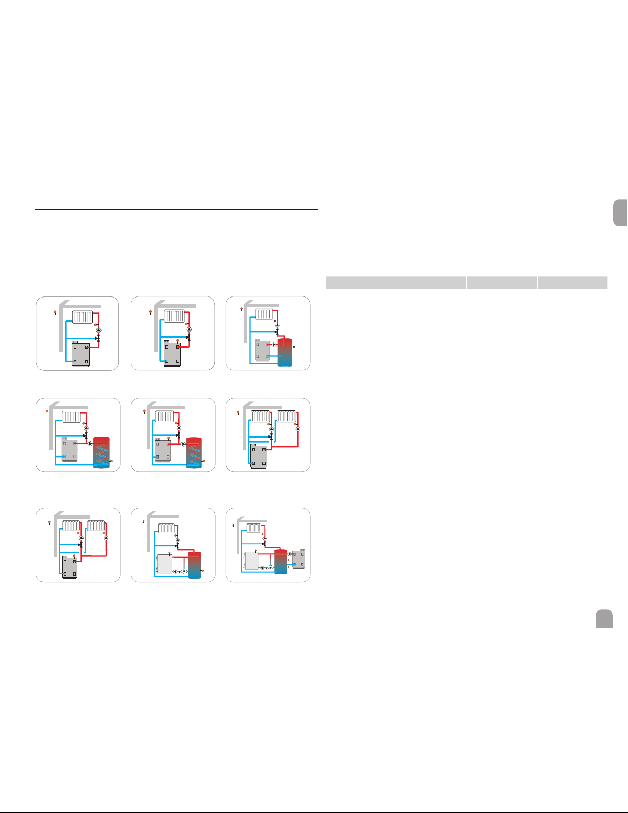
5.1 Schemes with basic settings
The controller is pre-programmed for 36 schemes. The basic pre-adjustments have
already been made. For backup heating it is necessary to allocate the demand and
the boiler loading pump by means of shared relays. Afterwards the system can easily
be extended.
Relay and sensor allocation correspond to the gures. Scheme 0 has no pre-adjustments.
1 mixed heating circuit
1 mixed heating circuit with
DHW heating
1 mixed and 1 unmixed
heating circuit with backup
heating
1 mixed heating circuit with
backup heating
1 mixed heating circuit with
DHW heating and backup
heating
1 mixed heating circuit with
solid fuel boiler
1 mixed heating circuit with
backup heating and loading pump
1 mixed and 1 unmixed
heating circuit
1 mixed heating circuit with
solid fuel boiler and backup
heating
5
8
6
9
1
4
7
2 3
Overview: 9 basic systems with one heating circuit
Each basic system has 4 schemes which result from the number of heating circuits.
The scheme number consists of 4 digits. The rst digit indicates the temperature
controls class. The second digit indicates the number of heating circuits, the third
and the fourth the desired basic system.
Example:
In order to select system 3 with the settings for 2 heating circuits, enter the scheme
number 0203.
0 2 0 3
Temperature controls
class
Number of heating
circuits
Number of the desired scheme; with a 0 in
front of it for numbers with 1 digit

22
en
Scheme 1: 1 mixed heating circuit
S1
S2
R1
R2/3
By means of the ow sensor S2 and the outdoor temperature sensor S1, a mixed
weather-compensated heating circuit can be controlled.
Scheme no. 0101 0201 0301 0401
Sensors
S1 Outdoor Outdoor Outdoor Outdoor
S2 Flow HC1 Flow HC1 Flow HC1 Flow HC1
S3 Flow HC2 Flow HC2 Flow HC2
S4 Flow HC3 Flow HC3
S5 Flow HC4
S6
S7
S8
S9
S10
S11
S12
Relay
R1 Pump HC1 Pump HC1 Pump HC1 Pump HC1
R2 Mixer open HC1 Mixer open HC1 Mixer open HC1 Mixer open HC1
R3 Mixer closed
HC1
Mixer closed
HC1
Mixer closed
HC1
Mixer closed
HC1
R4 Pump HC2 Pump HC2 Pump HC2
R5 Mixer open HC2 Mixer open HC2 Mixer open HC2
R6 Mixer closed
HC2
Mixer closed
HC2
Mixer closed
HC2
R7 Pump HC3 Pump HC3
R8 Mixer open HC3 Mixer open HC3
R9 Mixer closed
HC3
Mixer closed
HC3
R10 Pump HC4
R11 Mixer open HC4
R12 Mixer closed
HC4
R13
R14

23
en
Scheme 2: 1 mixed heating circuit with backup heating (demand)
S1
S2
R1
R2/3
S6
R14
By means of the ow sensor S2 and the outdoor temperature sensor S1, a mixed
weather-compensated heating circuit can be controlled. Boiler demand via the
potential-free relay is triggered depending on the temperature difference between
the set ow temperature and the value measured at the backup heating sensor S6.
Scheme no. 0102 0202 0302 0402
Sensors
S1 Outdoor Outdoor Outdoor Outdoor
S2 Flow HC1 Flow HC1 Flow HC1 Flow HC1
S3 Flow HC2 Flow HC2 Flow HC2
S4 Flow HC3 Flow HC3
S5 Flow HC4
S6 BH HC1 BH HC1,2 BH HC1,2,3 BH HC1,2,3,4
S7
S8
S9
S10
S11
S12
Relay
R1 Pump HC1 Pump HC1 Pump HC1 Pump HC1
R2 Mixer open HC1 Mixer open HC1 Mixer open HC1 Mixer open HC1
R3 Mixer closed
HC1
Mixer closed
HC1
Mixer closed
HC1
Mixer closed
HC1
R4 Pump HC2 Pump HC2 Pump HC2
R5 Mixer open HC2 Mixer open HC2 Mixer open HC2
R6 Mixer closed
HC2
Mixer closed
HC2
Mixer closed
HC2
R7 Pump HC3 Pump HC3
R8 Mixer open HC3 Mixer open HC3
R9 Mixer closed
HC3
Mixer closed
HC3
R10 Pump HC4
R11 Mixer open HC4
R12 Mixer closed
HC4
R13
R14 BH HC1 BH HC1,2 BH HC1,2,3 BH HC1,2,3,4
24
en
Scheme 3: 1 mixed heating circuit with backup heating
(demand and boiler loading pump)
S6
R14
S1
S2
R1
R2/3
R13
By means of the ow sensor S2 and the outdoor temperature sensor S1, a mixed
weather-compensated heating circuit can be controlled.
Boiler demand via the potential-free relay and boiler loading pump control are
triggered depending on the temperature difference between the set ow temperature and the value measured at the backup heating sensor S6.
Scheme no. 0103 0203 0303 0403
Sensors
S1 Outdoor Outdoor Outdoor Outdoor
S2 Flow HC1 Flow HC1 Flow HC1 Flow HC1
S3 Flow HC2 Flow HC2 Flow HC2
S4 Flow HC3 Flow HC3
S5 Flow HC4
S6 BH HC1 BH HC1,2 BH HC1,2,3 BH HC1,2,3,4
S7
S8
S9
S10
S11
S12
Relay
R1 Pump HC1 Pump HC1 Pump HC1 Pump HC1
R2 Mixer open HC1 Mixer open HC1 Mixer open HC1 Mixer open HC1
R3 Mixer closed
HC1
Mixer closed
HC1
Mixer closed
HC1
Mixer closed
HC1
R4 Pump HC2 Pump HC2 Pump HC2
R5 Mixer open HC2 Mixer open HC2 Mixer open HC2
R6 Mixer closed
HC2
Mixer closed
HC2
Mixer closed
HC2
R7 Pump HC3 Pump HC3
R8 Mixer open HC3 Mixer open HC3
R9 Mixer closed
HC3
Mixer closed
HC3
R10 Pump HC4
R11 Mixer open HC4
R12 Mixer closed
HC4
R13 Loading pump BHLoading pump BHLoading pump BHLoading pump
BH
R14 BH HC1 BH HC1,2 BH HC1,2,3 BH HC1,2,3,4

25
en
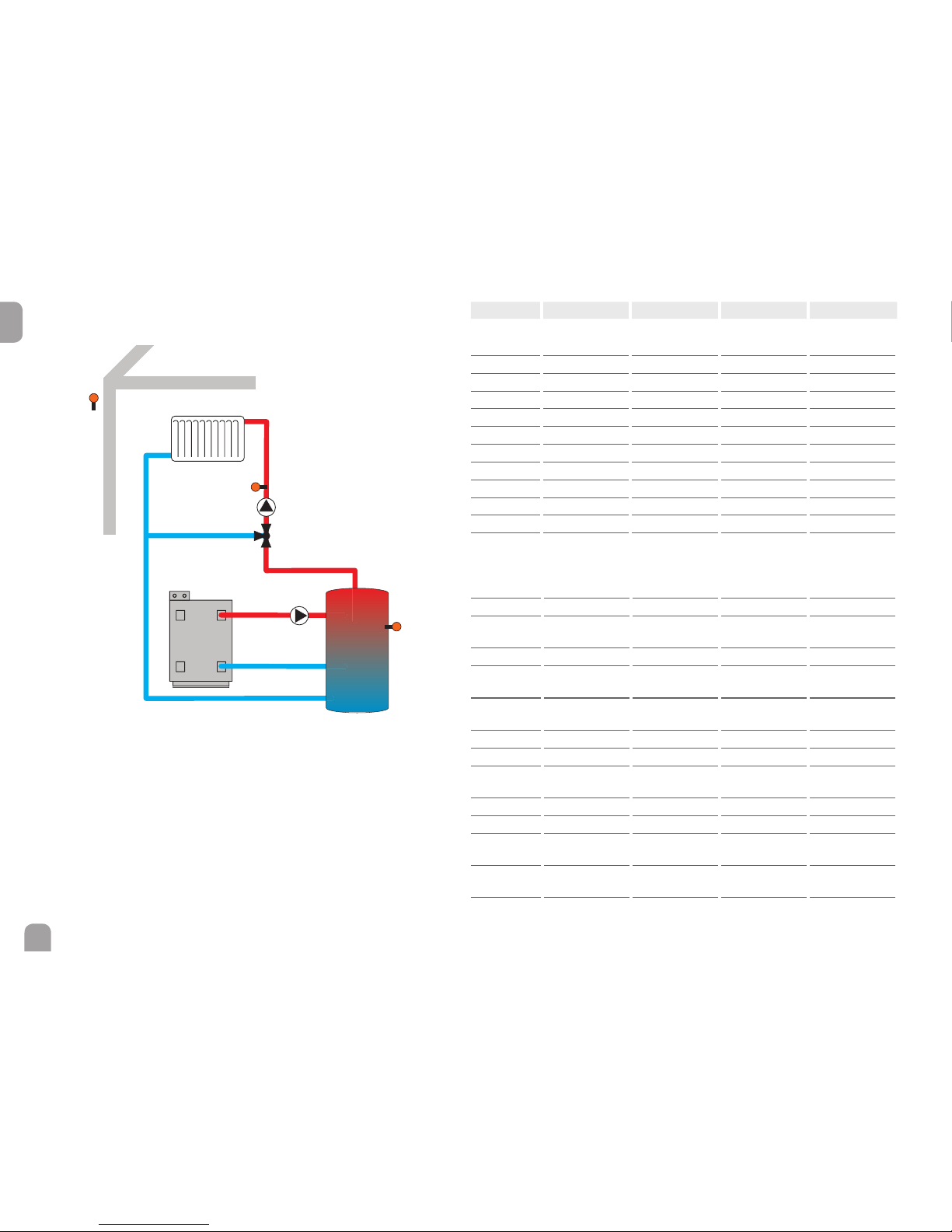
Scheme 4: 1 mixed heating circuit with DHW heating
S7
S1
S2
R1
R2/3
R14
By means of the ow sensor S2 and the outdoor temperature sensor S1, a mixed
weather-compensated heating circuit can be controlled. DHW heating is triggered
depending on the value measured at the DHW sensor S7.
Scheme no. 0104 0204 0304 0404
Sensors
S1 Outdoor Outdoor Outdoor Outdoor
S2 Flow HC1 Flow HC1 Flow HC1 Flow HC1
S3 Flow HC2 Flow HC2 Flow HC2
S4 Flow HC3 Flow HC3
S5 Flow HC4
S6
S7 DHW heating DHW heating DHW heating DHW heating
S8
S9
S10
S11
S12
Relay
R1 Pump HC1 Pump HC1 Pump HC1 Pump HC1
R2 Mixer open HC1 Mixer open HC1 Mixer open HC1 Mixer open HC1
R3 Mixer closed
HC1
Mixer closed
HC1
Mixer closed
HC1
Mixer closed
HC1
R4 Pump HC2 Pump HC2 Pump HC2
R5 Mixer open HC2 Mixer open HC2 Mixer open HC2
R6 Mixer closed
HC2
Mixer closed
HC2
Mixer closed
HC2
R7 Pump HC3 Pump HC3
R8 Mixer open HC3 Mixer open HC3
R9 Mixer closed
HC3
Mixer closed
HC3
R10 Pump HC4
R11 Mixer open HC4
R12 Mixer closed
HC4
R13
R14 DHW heating DHW heating DHW heating DHW heating

26
en
Scheme 5: 1 mixed heating circuit with DHW heating and backup heating (demand for heating circuit and DHW)
S7
S1
S2
R1
R2/3
S6
R14
By means of the ow sensor S2 and the outdoor temperature sensor S1, a mixed
weather-compensated heating circuit can be controlled. DHW heating is triggered
depending on the value measured at the DHW sensor S7. Boiler demand via the
potential-free relay is triggered depending on the temperature difference between
the set ow temperature and the value measured at the backup heating sensor S6.
Boiler demand can also be triggered by the temperature difference between the
DHW set temperature and the backup heating sensor S6.
Scheme no. 0105 0205 0305 0405
Sensors
S1 Outdoor Outdoor Outdoor Outdoor
S2 Flow HC1 Flow HC1 Flow HC1 Flow HC1
S3 Flow HC2 Flow HC2 Flow HC2
S4 Flow HC3 Flow HC3
S5 Flow HC4
S6 BH HC1 BH HC1,2 BH HC1,2,3 BH HC1,2,3,4
S7 DHW heating DHW heating DHW heating DHW heating
S8
S9
S10
S11
S12
Relay
R1 Pump HC1 Pump HC1 Pump HC1 Pump HC1
R2 Mixer open HC1 Mixer open HC1 Mixer open HC1 Mixer open HC1
R3 Mixer closed
HC1
Mixer closed
HC1
Mixer closed
HC1
Mixer closed
HC1
R4 Pump HC2 Pump HC2 Pump HC2
R5 Mixer open HC2 Mixer open HC2 Mixer open HC2
R6 Mixer closed
HC2
Mixer closed
HC2
Mixer closed
HC2
R7 Pump HC3 Pump HC3
R8 Mixer open HC3 Mixer open HC3
R9 Mixer closed
HC3
Mixer closed
HC3
R10 Pump HC4
R11 Mixer open HC4
R12 Mixer closed
HC4
R13
R14 DHW heating,
BH HC1
DHW heating,
BH HC1,2
DHW heating,
BH HC1,2,3
DHW heating,
BH HC1,2,3,4

27
en
Scheme 6: 1 mixed and 1 unmixed heating circuit
S1
S2
S9
R1
R2/3
R13
By means of the ow sensors S2 and S9 and the outdoor temperature sensor S1,
a mixed and an unmixed weather-compensated heating circuit can be controlled.
Scheme
no.
0106 0206 0306 0406
Sensors
S1 Outdoor Outdoor Outdoor Outdoor
S2 Flow HC1 Flow HC1 Flow HC1 Flow HC1
S3 Flow HC2 Flow HC2 Flow HC2
S4 Flow HC3 Flow HC3
S5 Flow HC4
S6
S7
S8
S9 Flow HC5 Flow HC5 Flow HC5 Flow HC5
S10
S11
S12
Relay
R1 Pump HC1 Pump HC1 Pump HC1 Pump HC1
R2 Mixer open HC1 Mixer open HC1 Mixer open HC1 Mixer open HC1
R3 Mixer closed
HC1
Mixer closed
HC1
Mixer closed
HC1
Mixer closed
HC1
R4 Pump HC2 Pump HC2 Pump HC2
R5 Mixer open HC2 Mixer open HC2 Mixer open HC2
R6 Mixer closed
HC2
Mixer closed
HC2
Mixer closed
HC2
R7 Pump HC3 Pump HC3
R8 Mixer open HC3 Mixer open HC3
R9 Mixer closed
HC3
Mixer closed
HC3
R10 Pump HC4
R11 Mixer open HC4
R12 Mixer closed
HC4
R13 Pump HC5 Pump HC5 Pump HC5 Pump HC5
R14

28
en
Scheme 7: 1 mixed and 1 unmixed heating circuit with backup heating
(demand)
S1
S2
S7
R1
R2/3
R13
S6
R14
By means of the ow sensors S2 and S7 and the outdoor temperature sensor S1,
a mixed and an unmixed weather-compensated heating circuit can be controlled.
Boiler demand via the potential-free relay is triggered depending on the temperature difference between the set ow temperatures and the value measured at the
backup heating sensor S6.
Scheme no. 0107 0207 0307 0407
Sensors
S1 Outdoor Outdoor Outdoor Outdoor
S2 Flow HC1 Flow HC1 Flow HC1 Flow HC1
S3 Flow HC2 Flow HC2 Flow HC2
S4 Flow HC3 Flow HC3
S5 Flow HC4
S6 BH HC1,5 BH HC1,2,5 BH HC1,2,3,5 BH HC1,2,3,4,5
S7 Flow HC5 Flow HC5 Flow HC5 Flow HC5
S8
S9
S10
S11
S12
Relay
R1 Pump HC1 Pump HC1 Pump HC1 Pump HC1
R2 Mixer open HC1 Mixer open HC1 Mixer open HC1 Mixer open HC1
R3 Mixer closed
HC1
Mixer closed
HC1
Mixer closed
HC1
Mixer closed
HC1
R4 Pump HC2 Pump HC2 Pump HC2
R5 Mixer open HC2 Mixer open HC2 Mixer open HC2
R6 Mixer closed
HC2
Mixer closed
HC2
Mixer closed
HC2
R7 Pump HC3 Pump HC3
R8 Mixer open HC3 Mixer open HC3
R9 Mixer closed
HC3
Mixer closed
HC3
R10 Pump HC4
R11 Mixer open HC4
R12 Mixer closed
HC4
R13 Pump HC5 Pump HC5 Pump HC5 Pump HC5
R14 BH HC1,5 BH HC1,2,5 BH HC1,2,3,5 BH HC1,2,3,4,5

29
en
Scheme 8: 1 mixed heating circuit with solid fuel boiler
S9
S1
S2
R1
R2/3
S8
R13
By means of the ow sensor S2 and the outdoor temperature sensor S1, a mixed
weather-compensated heating circuit can be controlled. The solid fuel boiler is
controlled depending on the temperature difference between the sensors S8 (solid fuel boiler) and S9 (store).
Scheme no. 0108 0208 0308 0408
Sensors
S1 Outdoor Outdoor Outdoor Outdoor
S2 Flow HC1 Flow HC1 Flow HC1 Flow HC1
S3 Flow HC2 Flow HC2 Flow HC2
S4 Flow HC3 Flow HC3
S5 Flow HC4
S6
S7
S8 Boiler SFB Boiler SFB Boiler SFB Boiler SFB
S9 Store SFB Store SFB Store SFB Store SFB
S10
S11
S12
Relay
R1 Pump HC1 Pump HC1 Pump HC1 Pump HC1
R2 Mixer open HC1 Mixer open HC1 Mixer open HC1 Mixer open HC1
R3 Mixer closed
HC1
Mixer closed
HC1
Mixer closed
HC1
Mixer closed
HC1
R4 Pump HC2 Pump HC2 Pump HC2
R5 Mixer open HC2 Mixer open HC2 Mixer open HC2
R6 Mixer closed
HC2
Mixer closed
HC2
Mixer closed
HC2
R7 Pump HC3 Pump HC3
R8 Mixer open HC3 Mixer open HC3
R9 Mixer closed
HC3
Mixer closed
HC3
R10 Pump HC4
R11 Mixer open HC4
R12 Mixer closed
HC4
R13 Pump SFB Pump SFB Pump SFB Pump SFB
R14

30
en
Scheme 9: 1 mixed heating circuit with solid fuel boiler and backup heating (demand)
S9
R14
S1
S2
R1
R2/3
S8
R13
S6
By means of the ow sensor S2 and the outdoor temperature sensor S1, a mixed
weather-compensated heating circuit can be controlled. Boiler demand via the
potential-free relay is triggered depending on the temperature difference between
the set ow temperature and the value measured at the backup heating sensor
S6. The solid fuel boiler is controlled depending on the temperature difference
between the sensors S8 (solid fuel boiler) and S9 (store).
Scheme no. 0109 0209 0309 0409
Sensors
S1 Outdoor Outdoor Outdoor Outdoor
S2 Flow HC1 Flow HC1 Flow HC1 Flow HC1
S3 Flow HC2 Flow HC2 Flow HC2
S4 Flow HC3 Flow HC3
S5 Flow HC4
S6 BH HC1 BH HC1,2 BH HC1,2,3 BH HC1,2,3,4
S7
S8 Boiler SFB Boiler SFB Boiler SFB Boiler SFB
S9 Store SFB Store SFB Store SFB Store SFB
S10
S11
S12
Relay
R1 Pump HC1 Pump HC1 Pump HC1 Pump HC1
R2 Mixer open HC1 Mixer open HC1 Mixer open HC1 Mixer open HC1
R3 Mixer closed
HC1
Mixer closed
HC1
Mixer closed
HC1
Mixer closed
HC1
R4 Pump HC2 Pump HC2 Pump HC2
R5 Mixer open HC2 Mixer open HC2 Mixer open HC2
R6 Mixer closed
HC2
Mixer closed
HC2
Mixer closed
HC2
R7 Pump HC3 Pump HC3
R8 Mixer open HC3 Mixer open HC3
R9 Mixer closed
HC3
Mixer closed
HC3
R10 Pump HC4
R11 Mixer open HC4
R12 Mixer closed
HC4
R13 Pump SFB Pump SFB Pump SFB Pump SFB
R14 BH HC1 BH HC1,2 BH HC1,2,3 BH HC1,2,3,4

31
en
6 Main menu
In this menu, different menu areas can be selected.
The following menus are available:
• Status
• Heating
• Arrangement
• HQM
• Basic settings
• SD card
• Manual mode
• User code
• Inputs / Modules
Î Select the menu area by pressing buttons ❶ and ❸.
Î Press button ➄ in order to enter the selected menu area.
Note
If no button is pressed for 1 min, the display illumination switches off.
After 4 further minutes, the controller will display the home screen (see
page 34).
Î In order to get from the Status menu into the Main menu, press but-
ton ➆.

32
en
Main menu
Status
Heating
Arrangement
HQM
Basic settings
SD card
Manual mode
User code
Inputs / Modules
Arrangement
Optional functions
Optional functions
Parallel relay
Mixer
Zone loading
Error relay
…
Heating
Shared relays
Heating circuits
Optional functions
Parallel relay
Output
Reference relay
Overrun
Delay
Speed
…
Basic settings
Language
Auto DST
Date
Time
Temp. unit
Flow unit
…
Inputs / Modules
Modules
Inputs
6.1 Menu structure
Note
The menu items and adjustment values selectable are variable depending
on adjustments already made. The gure only shows an exemplary excerpt
of the complete menu in order to visualise the menu structure.

33
en
7 Status
In the status menu of the controller, the status messages for every menu area can
be found.
Use the buttons ❷ and ❹ for scrolling through the status menu.
❷
❹
At the end of each submenu, the menu item Adjustment values can be found.
If Adjustment values is selected, the corresponding menu will open.
Î In order to get back to the status menu, press button ➆.
7.1 Measured / Balance values
In the Status / Meas. / Balance values menu, all current measurement values as
well as a range of balance values are displayed. Some of the menu items can be
selected in order to enter a submenu.
Each sensor and relay is indicated with the component or function it has been
allocated to. The symbol ▶ at the edge of the display next to a sensor allocated to
a function, means that this sensor has several functions. Use buttons ❷ and ❹ to
scroll to these functions. The sensors and relays of the controller and all modules
connected are listed in numerical order.
7.2 Heating
In the Status / Heating menu, the status of the demands and heating circuits
activated as well as of the selected optional functions is indicated.
7.3 Arrangement
The Status / Arrangement menu shows all status information of all activated op-
tional functions of the arrangement.
7.4 HQM
In the Status / HQM menu, all current measured values of the ow and return
sensors, ow rate and power as well as heat quantities are indicated.

34
en
7.5 Messages
In the Status / Messages menu, error and warning messages are indicated.
During normal operation, the message Everything OK is indicated.
A message consists of the name of the monitoring function, a 4-digit error code and
a short text description of the fault condition.
In order to acknowledge a message, proceed as follows:
Î Select the code line of the desired message by pressing buttons ❶ and ❸.
Î Acknowledge the message by pressing button ➄.
Î Conrm the security enquiry by selecting Ye s .
When the installer user code has been entered, the menu item Restarts will ap-
pear below the messages. The value indicates the number of controller restarts
since commissioning. This value cannot be reset.
Error
code
Display Monitoring function Cause
0001 !Sensor fault! Sensor line break Sensor line broken
0002 !Sensor fault! Sensor short circuit Sensor line short-circuited
0061 !Data storage!
Storing and changing adjustments not possible
0071 !RTC!
Time-controlled functions
(e. g. night correction) not
possible
0091 Restarts
Restart counter
(non-adjustable)
Number of restarts since
commissioning
7.6 Home screen
In the Home screen menu, the menu which will appear if no button is pressed for
a longer period of time can be selected.
8 Heating
In this menu, all adjustments for the heating part of the arrangement or for the
heating circuits respectively can be made.
Shared relays for demands, loading pumps or valves can be activated, heating circuits
can be congured and optional functions can be selected and adjusted.
In this menu, the screed drying function can be activated and adjusted.
8.1 Shared relays
In this menu, adjustments for heat generators which are shared by several heating
circuits and their optional functions can be made.
Shared relays will be available for selection under Virtual in the heating circuits
and in the relay allocation channels of the corresponding optional functions of the
Heating menu. This way, several heating circuits and optional functions (heating) can
demand the same heat source.

35
en
Note
Activate and adjust the shared relays rst. They will then be available in
the heating circuits and optional functions.
Heating / Shared rel.
Adjustment
channel
Description
Adjustment range /
selection
Factory setting
Dem. 1 (2) Demand 1 (2) Activated, Deactivated Deactivated
Relay Relay option Yes, No No
Relay Relay submenu - -
Relay Relay selection system dependent
system dependent
Boiler pr. min Option for boiler protection min Yes, No No
Tmin Minimum boiler temperature 10 … 90 °C 55 °C
Boiler pr. max Option for boiler protection max Yes, No No
Tmax Maximum boiler temperature 20 … 95 °C 90 °C
Sen. boiler Boiler sensor selection system dependent S4
0-10 V 0-10 V option Yes, No No
0-10 V 0-10 V submenu - -
Output Output selection -, A, B, C, D -
TSet 1 Lower boiler temperature 10 … 85 °C 10 °C
Volt 1 Lower voltage 1.0 … 10.0 V 1.0 V
TSet 2 Upper boiler temperature 15 … 90 °C 80 °C
Volt 2 Upper voltage 1.0 … 10.0 V 8.0 V
Tmin
Minimum value set boiler temperature
10 … 89 °C 10 °C
Tmax
Maximum value set boiler
temperature
11 … 90 °C 80 °C
DTFlow
Increase for the set ow tem-
perature
0 … 20 K 5 K
Sen. ow Flow sensor option Yes, No No
Adjustment
channel
Description
Adjustment range /
selection
Factory setting
Sensor Flow sensor selection system dependent S4
Interval Monitoring period 10 … 600 s 30 s
Hyst. Correction hysteresis 0.5 … 20.0 K 1.0 K
Correction Correction of the voltage signal 0.0 … 1.0 V 0.1 V
Min. runt. Minimum runtime option Yes, No No
tMin Minimum runtime 0 … 120 min 10 min
Manual mode Operating mode for shared relays Max, Auto, Off, Min Auto
back
In this menu, up to 2 heating demands can be activated and adjusted.
Activated demands will be available for selection in the output allocation
channels of the backup heating in heating circuits and heating optional
functions. This way, several heating circuits and optional functions can
demand the same heat source.
Every demand can be carried out by means of a relay and/or a 0-10 V output. If both
the relay and the 0-10 V option are activated, the demand will use both outputs in
parallel.
Relay option
If the Relay option is activated, the submenu Relay will appear, in which a relay can
be allocated to the demand.
The options Boiler protection min and Boiler protection max can be activat-
ed for the demand via a relay, allowing temperature-dependent control of the boiler
demand. For this purpose, a Boiler sensor has to be selected.
The Boiler protection min option is used for protecting an older type boiler
against cooling. If the temperature falls below the adjusted minimum temperature,
the allocated relay will be energised until the minimum temperature is exceeded
by 5 K.
The Boiler protection max option is used for protecting an older type boiler
against overheating. If the adjusted Maximum temperature is exceeded, the allocat-
ed relay will be switched off until the temperature falls by 5 K below the maximum
temperature.
Example:
The potential-free relay R14 can be allocated to the shared relay Demand 1. R14
will then become available for potential-free boiler demand in the heating circuits
and e. g. the DHW heating function.

36
en
0-10 V option
If the 0-10 V option is activated, the submenu 0-10 V will appear, in which a 0-10 V
output can be allocated to the demand.
With this option, the controller can demand modulating heat generators equipped
with a 0-10 V interface.
The characteristic curve of the 0-10 V signal as a function of the set boiler temperature is dened by means of 2 set points according to the specications of the boiler
manufacturer. At a temperature of Tset 1, the voltage signal of the heat generator
is Volt 1. At a temperature of Tset 2, the voltage signal of the heat generator is
Volt 2. The controller automatically calculates the characteristic curve resulting
from these values.
Set boiler temperature in °C
Voltage signal in V
By means of the adjustment channels Tmax and Tmin the maximum and mini-
mum values for the set boiler temperature can be dened.
When the Sensorow option is activated, the controller will monitor whether
the heat generator actually reaches the desired set temperature and will, if necessary, adjust the voltage signal accordingly. In order to do so, the controller will
check the temperature at the boiler ow sensor when the Interval has elapsed. If
the temperature measured deviates from the boiler set temperature by more than
the Hysteresis value, the voltage signal will be adapted by the Correction value.
This process will be repeated until the temperature measured is identical to the set
boiler temperature.
When the Min. runtime option is activated, a Minimum runtime can be adjust-
ed for the demand.
Note
If the 0-10 V demand is used for DHW heating, the voltage signal will always
be identical to Tmax.
8.2 Heating circuits
The controller has 4 mixed weather-compensated heating circuits and is able to
control up to 3 external mixed heating circuits by means of extension modules.
If one or more extension modules are connected, they have to be registered with
the controller. Only registered modules will be available in the heating circuit se-
lection.
If New HC… is selected for the rst time, the rst heating circuit is allocated to
the controller.
In the heating circuit menu, relays for the heating circuit pump and the heating
circuit mixer can be selected.
3 free relays are required for a mixed heating circuit.
If the measured ow temperature deviates from the Set ow temperature, the
mixer will be activated in order to adjust the ow temperature correspondingly.
The mixer runtime can be adjusted with the parameter Interval.

37
en
Heating system submenu
In the Heating system submenu, a Mode for the heating circuit control can be
selected and adjusted. 5 modes are available:
• Constant
• Curve
• Linear
• Room inuence
• Room
The constant mode aims to keep the set ow temperature at a constant value
which can be adjusted by means of the parameter Towset.
Set ow temperature = set temperature + remote control + day correction or
night correction
If the Curve mode is selected, the controller will calculate a set ow temperature
by means of the outdoor temperature and the Heating curve selected. In both
cases, the dial setting of the remote control and the controller Day correction or
Night correction will be added.
Set ow temperature = heating curve temperature + remote control + day correction or night correction.
The Remote control allows manual adjustment of the heating curve (± 15 K). Furthermore, the heating circuit can be switched off or a rapid heat-up can be carried
out by means of the remote control.
Heating circuit switched off means that the heating circuit pump is switched off and
the mixer closed. The ow temperature is boosted to maximum for rapid heat-up
when the remote control is set to rapid heat-up.
The calculated set ow temperature is limited by the adjusted values of the param-
eters maximumowtemperature and minimumowtemperature.
Maximum ow temperature ≥ set ow temperature ≥ minimum ow temperature
If the outdoor temperature sensor is defective, an error message will be indicated.
For the duration of this condition, the maximum ow temperature -5 K is assumed
as the set ow temperature in the Curve and Linear mode.
In the Linear mode the ow temperature curve will be calculated depending on
the outdoor temperature by 2 points. At a temperature of TOutdoor 1 the set
ow temperature is TFlow 1. At a temperature of TOutdoor 2 the set ow
temperature is TFlow 2. The controller automatically calculates the characteristic
curve resulting from these values.
By means of the adjustment channels Towmax and Towmin the maximum and
minimum values for the set ow temperature can be dened.
In the Room inuence mode, the weather-compensated set ow temperature
will be expanded by a demand-based room control. The parameter Room factor
can be used for determining the intensity of the room inuence.
The controller will calculate the set ow temperature using the heating system
Curve plus the room inuence: Set ow temperature = set temperature + remote
control + day correction or night correction + room inuence.
In order to calculate the deviation of the room temperature from the adjusted set
value, at least one sensor-type room thermostat is required. The adjustments can be
made in the Room thermostats submenu, Room therm. (1 ... 5).

38
en
1,0
Flow temperature in °C
Outdoor temperature in °C
Heating curves
20
30
40
50
60
70
In the Room mode, the controller will calculate the set ow temperature by means
of the room temperature, the outdoor temperature will not be taken into account.
The parameters Day- / Night correction and Timer will not be indicated.
The start value of the set ow temperature can be inuenced by the parameter
TStart.
In order to calculate the deviation of the room temperature from the adjusted
set value, a room thermostat is required. The adjustments can be made using the
parameter RTH(1 … 5) . For this purpose, select Sensor in the Type adjustment
channel.
The adjustments of all activated room thermostats will be taken into account. The
controller will calculate the average value of the deviations measured and correct
the set ow temperature correspondingly.
Room thermostat option
With the Room thermostat option, up to 5 room thermostats can be integrated
into the control logic.
To each room thermostat, a sensor input can be allocated. The temperature at the
allocated sensor is monitored. If the measured temperature exceeds the adjusted
Set room temperature at all activated room thermostats and if the parameter
HC off is activated, the heating circuit will switch off.
Common room thermostats with potential-free outputs can be used alternatively.
In this case, Switch must be selected in the Type channel. The corresponding input
must beforehand be set to Switch in the Inputs / Modules menu. Only inputs set
to switch will be displayed in the channel Sensor RTH as possible inputs for a
switch type room thermostat.
When the Timer option is activated, a timer is indicated in which time frames for
the function can be adjusted. Outside these time frames, the adjusted room temperature is decreased by the Correction value.
If the Special operation Cooling is active, the set room temperature will
increase by the Correction value.
Note
For information on timer adjustment see page 12.

39
en
To each room thermostat, an additional relay can be allocated. The relay will switch
on when the temperature falls below the adjusted room temperature. This way, the
room in question can be excluded from the heating circuit via a valve as long as the
desired room temperature is reached.
With the parameter RTH, the room thermostat can be temporarily deactivated or
re-activated respectively. All adjustments remain stored.
Correction timer
With the Timer, the day / night operation can be adjusted. During day phases, the
set ow temperature is increased by the adjusted day correction value, during
night phases it is decreased by the night correction value (night setback).
The parameter Mode is used for selecting between the following correction modes:
Day / Night: A reduced set ow temperature (night correction) is used during
Night operation.
Day / Off: The heating circuit and the optionally activated backup heating are
switched off during night operation.
The Timer HC can be used for adjusting the time frames for day operation.
Summer operation
For summer operation, 2 different modes are available:
Day: If the outdoor temperature exceeds the Summer temperature day, the
heating circuit will switch off.
Day / Night: The parameters Daytime on and Daytime off can be used for
adjusting a time frame for the summer operation. If the outdoor temperature ex-
ceeds the Summer temperature day within the adjusted time frame, the heating
circuit will switch off.
Outside the adjusted time frame the Summer temperature night is valid.

40
en
Remote access
With the parameter Remote access different types of remote access to the con-
troller can be activated.
Note
In the sensor selection menu, only outputs which have previously been
selected as the input for remote access in the Inputs / Modules menu
will be available.
The following types of remote access are possible:
Remote control: A device which allows manual adjustment of the heating curve,
thus inuencing the set ow temperature.
Î In order to use a remote control, set the Mode to Fern.
Room control unit: A device incorporating a remote control as well as an addi-
tional operating mode switch.
Î In order to use a room control unit, set the Mode to BAS.
The operating mode switch of the room control unit is used for adjusting the oper-
ating mode of the controller. If a room control unit is used, the operating mode can
be adjusted by means of the room control unit only. The controller menu will only
allow the activation of the operating mode Holiday.
App: An app can be used for remote access.
Î In order to use an app, set the Mode to App.
If you use an app, the operating mode can be adjusted in the controller menu as
well as in the app.
Backup heating
For the Backup heating of the heating circuit, 3 modes are available:
In the Therm. mode, the set ow temperature will be compared to a store ref-
erence sensor.
In the Zone mode, the set ow temperature will be compared to 2 store reference
sensors. The switching conditions have to be fullled at both reference sensors.
In the On / Off mode, the backup heating will be activated when the heating circuit
pump is switched on for heating.
In the Demand submenu, the modes standard and Demand are available. If
Standard is selected, the output can be adjusted.

41
en
If Demand is selected, a demand has to be activated and adjusted in the Heating /
Shared relays menu rst. If Adjustment values is selected, the Heating / Shared
relays / Demand menu will open.
In the correction mode Day / off (see page 39) the heating circuit and the backup
heating will be completely switched off during the night operation. The Starting
optimisation option can be used for activating the backup heating before the day
operation in order to heat the store to a sufciently high temperature. The Stop-
ping optimisation option can be used for deactivating the backup heating before
the start of the night operation.
If SFB off is activated, backup heating will be suppressed when a selected solid fuel
boiler is active.
At rst, backup heating is activated and can be temporarily deactivated.
DHW priority
If the parameter DHW priority is activated, the heating circuit will be switched off
and the backup heating be suppressed as long as DHW heating takes place which
has previously been activated in the Heating / Optional functions menu.
Chimney sweeper function
The chimney sweeper function can be used for enabling a quick access to measure-
ment conditions without menu operation for the chimney sweeper.
The chimney sweeper function is activated in all heating circuits by default. The
chimney sweeper mode can be activated by pressing button ➅ for 5 s.
In the chimney sweeper mode, the heating circuit mixer opens, the heating circuit
pump and the backup heating contact are activated. While the chimney sweeper
mode is active, the directional pad is ashing red. Additionally, Chimney sweeper
and a countdown of 30 min are indicated on the display.
When the countdown has elapsed, the chimney sweeper mode is automatically
deactivated. If, during the countdown, button ➅ is again pressed for more than 5 s,
the chimney sweeper mode will stop.
Antifreeze function
The antifreeze function of the heating circuit can be used to temporarily activate
an inactive heating circuit during sudden temperature drop in order to protect it
against frost damage.
The temperature at the sensor selected will be monitored. If the temperature falls
below the adjusted antifreeze temperature, the heating circuit will be activated until
the antifreeze temperature is exceeded by 2 K, but at least for 30 min.

42
en
Special operation
For the Special operation option, 2 variants are available:
• Cooling
• Heat dump
The Cooling variant is used for cooling via the heating circuit. 3 modes are available:
• Outdoor
• External switch
• Both
In the Outdoor mode, cooling will be activated if the outdoor temperature
cooling is exceeded.
In the External switch mode, cooling will be activated by means of an external
switch.
In the both mode, both switching conditions are valid for cooling.
In the Cooling system submenu, the cooling logic can be adjusted. For the cooling
logic, 2 modes are available:
• Linear
• Constant
In the Linear mode, the set ow temperature will be calculated as in the heating
system mode Linear.
The Constant mode aims to keep the set ow temperature at a constant value
which can be adjusted by means of the parameter TFlow.
If the Timer option is activated, a time frame can be adjusted in which the cooling
will be active.
If the Dew point switch option is activated, an output can be allocated to the
dew point switch. If the dew point switch detects condensation, cooling will be
interrupted.
The Heat dump variant is used for diverting excess heat to the heating circuit in
order to keep the system temperatures within the operating range. For this purpose, the temperature measured at the allocated sensor Sensor will be monitored.
If the temperature at the allocated sensor exceeds the Switch-on temperature,
the Setowtemperature will be controlled to reach the adjusted value. If the
temperature at the allocated sensor falls below the adjusted Switch-off temper-
ature, the heat dump function will switch off.
Energy saving operation
The Energy saving operation is used for optimising the energy consumption of
the heating circuit pump. For this purpose an additional sensor in the heating circuit
return is required. The controller monitors the temperature difference between the
ow and the return of the heating circuit. If the temperature difference falls below
the Switch-off difference, the controller will deactivate the heating circuit pump
for the adjusted Break time. After the break time has elapsed, the pump will be
activated for the Runtime. If the temperature difference is higher than the switch-
off difference, the pump will remain active. If the temperature difference is below
the switch-off difference, the break time will start again.

43
en
Heating / Heating circuits / New HC... / Internal or Module 1 … 5
Adjustment
channel
Description
Adjustment range
/ selection
Factory setting
Heat. sys. Heating system submenu - -
Mode Heating system operating mode
Linear, Constant,
Curve, Room, Room
in. Curve
Curve Heating curve 0.3 … 3.0 1.0
Room factor Room inuence factor 1 … 10 5
TFlowset Set ow temperature 10 … 90 °C 45 °C
TOutdoor 1 Lower outdoor temperature -20 … +20 °C +20 °C
TFlow 1 Lower set ow temperature 20 … 90 °C 20 °C
TOutdoor 2 Upper outdoor temperature -20 … +20 °C -20 °C
TFlow 2 Upper set ow temperature 20 … 90 °C 70 °C
TStart Start temperature 20 … 60 °C 40 °C
TFlowmin Minimum ow temperature 20 … 89 °C 20 °C
TFlowmax Maximum ow temperature 21 … 90 °C 50 °C
Interval Mixer interval 1 … 20 s 4 s
HC pump
Heating circuit pump output
selection
system dependent system dependent
Mixer open Output selection mixer open system dependent system dependent
Mixer closed Output selection mixer closed system dependent system dependent
Sen. ow Flow sensor selection system dependent system dependent
Sen. outd.
Outdoor sensor selection
system dependent system dependent
Day corr. Correction for day operation -5 … +45 K 0 K
Night corr. Correction for night operation -20 … +30 K -5 K
Timer Timer option Yes, No No
Timer Timer submenu - Mode Correction mode Day / Night, Day / Off Day / Night
Summer oper. Summer operation option Yes, No No
Summer oper. Summer operation submenu - Mode Summer operating mode Day / Night, Day Day
TDay off Summer temperature day 0 … 40 °C 20 °C
TNight off Summer temperature night 0 … 40 °C 14 °C
Daytime on Day time frame on 00:00 … 23:45 00:00
Daytime off Day time frame off 00:00 … 23:45 00:00
Remote
access
Remote access option Yes, No No
Adjustment
channel
Description
Adjustment range
/ selection
Factory setting
Remote
access
Remote access submenu - -
Mode Remote access mode BAS, Fern, App BAS
Sen. BAS
Allocation operating mode switch
input
all inputs type = BAS -
Sen. RC Allocation remote control input all inputs type = Fern Room therm. Room thermostats submenu - Room therm.
1 … 5
Room thermostat option (1 … 5) Yes, No No
Type Room thermostat type selection Sensor, Switch Sensor
Sensor RTH RTH input allocation system dependent system dependent
TAmb.set Set room temperature 10 … 30 °C 18 °C
Hysteresis RTH hysteresis 0.5 … 20.0 K 0.5 K
Timer RTH timer Yes, No No
Correction Correction value 1 … 20 K 5 K
Relay RTH relay selection system dependent system dependent
RTH Room thermostat Activated, Deactivated Activated
HC off Heating circuit off option Yes, No Ye s
Backup
heating
Backup heating option Yes, No No
Backup
heating
Backup heating submenu - -
Mode Backup heating mode selection Therm., Zone, On/Off Therm.
Output Output selection system dependent system dependent
Sensor 1 Allocation reference sensor 1 system dependent system dependent
Sensor 2
Allocation reference sensor 2
(if mode = Zone)
system dependent system dependent
DTo n Switch-on temperature difference -15.0 … 44.5 K 5.0 K
DToff Switch-off temperature difference -14.5 … 45.0 K 15.0 K
Loading
pump
Boiler loading pump option Yes, No No
Start. opt. Starting optimisation option Yes, No No
Time Time starting optimisation 0 … 300 min 60 min
Stopp. opt. Stopping optimisation option Yes, No No
Time Time stopping optimisation 0 … 300 min 60 min
SFB off Solid fuel boiler off option Yes, No No
SFB Allocation solid fuel boiler all solid fuel boilers -

44
en
Adjustment
channel
Description
Adjustment range
/ selection
Factory setting
DHW
priority
DHW priority option Yes, No No
Chimney
sweeper
Chimney sweeper option Yes, No Ye s
Antifreeze Antifreeze option Yes, No No
Sensor Antifreeze sensor Flow, Outdoor Flow
TAntifr. Antifreeze temperature -20 … +10 °C +5 °C
TFlowset Set ow temperature antifreeze 20 … 50 °C 20 °C
Special oper. Special operation option Yes, No No
Special oper. Special operation submenu - -
Type Special operation variant Cooling, Heat dump
Output Output selection system dependent system dependent
Mode Cooling mode
Outdoor, Ext. switch,
Both
-
Sensor Switch input selection - Inverted Inverted switching option Yes, No No
TDay off Outdoor temperature cooling 20 … 40 °C 20 °C
Cooling
system
Cooling system submenu - -
Type Cooling mode Linear, Constant Constant
TFlow Cooling ow temperature 5 … 25 °C 20 °C
TOutdoor 1 Lower outdoor temperature 15 … 45 °C 20 °C
TFlow 1 Lower set ow temperature 5 … 25 °C 20 °C
TOutdoor 2 Upper outdoor temperature 15 … 45 °C 40 °C
TFlow 2 Upper set ow temperature 5 … 25 °C 10 °C
Towmin Minimum ow temperature 5 … 29 °C 10 °C
TFlowmax Maximum ow temperature 6 … 30 °C 25 °C
Timer Timer option cooling Yes, No No
tOn Switch-on time cooling 00:00 … 23:45 00:00
tOff Switch-off time cooling 00:00 … 23:45 00:00
Dew point
switch
Dew point switch (DPS) option Yes, No No
Sensor Allocation DPS input system dependent system dependent
Output Output selection system dependent system dependent
Sensor
Allocation heat dump sensor
system dependent system dependent
To n Switch-on temperature heat dump 25 … 95 °C 85 °C
Toff Switch-off temperature heat dump 20 … 90 °C 50 °C
Adjustment
channel
Description
Adjustment range
/ selection
Factory setting
TFlowset Set ow temperature heat dump 5 … 90 °C 50 °C
Energy saving Energy saving operation option Yes, No No
Energy saving Energy saving operation submenu - -
Sen. return HC return sensor allocation system dependent system dependent
DToff
Switch-off temperature difference
energy saving operation
1 … 49 K 4 K
Break Break time energy saving operation 0 … 60 min 15 min
Runtime Runtime energy saving operation 0 … 60 min 2 min
Funct. De/activation of the heating circuit
Activated, Deactivated,
Switch
Activated
Sensor Switch input selection - -
Save / Delete
function
Save or delete function - -
8.3 Optional functions
In this menu, optional functions can be selected and adjusted for the heating part
of the arrangement.
The kind and number of optional functions offered depends on the previous ad-
justments.
Note
For further information about adjusting optional functions, see page 14.
In the Demand submenu, the modes standard and Demand are available. If
Standard is selected, the output can be adjusted. If Demand is selected, a demand
has to be activated and adjusted in the Heating/ Shared rel. rst. If Adjustment
values is selected, the Heating/ Shared rel. / Demand will open.
Note
For information on the output selection see page 16.

45
en
Thermal disinfection
This function helps to contain the spread of Legionella in DHW stores by system-
atically activating the backup heating.
One Sensor and one output or Demand respectively can be selected for this
function.
For thermal disinfection, the temperature at the allocated sensor has to be monitored. Protection is ensured when, during the Monitoring period, the disinfec-
tion temperature is continuously exceeded for the entire Disinfection period.
The monitoring period starts as soon as the temperature at the allocated sensor
falls below the disinfection temperature. If the monitoring period ends, the Demand will activate the backup heating. The Disinfection period starts when the
temperature at the allocated Sensor exceeds the disinfection temperature.
Thermal disinfection can only be completed when the Disinfection temperature
is exceeded for the duration of the Disinfection period without any interruption.
The parameter Cancellation is used for adjusting the period after which the
non-completed backup heating will be cancelled. If the backup heating is cancelled,
an error message will be displayed.
Starting time delay
If the Starting delay option is activated, a starting time for the thermal disinfection
with starting delay can be adjusted. The activation of the backup heating is then
delayed until that starting time after the monitoring period has ended.
If the monitoring period ends, for example, at 12:00 o'clock, and the starting time
has been set to 18:00, the reference relay will be energised with a delay of 6 hours
at 18:00 instead of 12:00 o'clock.
Heating / Opt. functions / Add new function / Th. Disinfection
Adjustment
channel
Description
Adjustment range /
selection
Factory setting
Demand Demand relay selection system dependent
system dependent
Circulating
pump
Circulating pump option Yes, No No
Output
Circulating pump output
selection
system dependent
system dependent
Sensor Disinfection sensor selection system dependent
system dependent
Interval Monitoring period 0 … 30, 1 … 23 (dd:hh) 1d 0h
Temperature Disinfection temperature 45 … 90 °C 60 °C
Duration Disinfection period 0.5 … 24.0 h 1.0 h
Cancellation Cancellation option Yes, No No
Cancellation Cancellation interval 1.0 … 48.0 h 2.0 h
Start. time Starting delay option Yes, No No
Start. time Starting time 00:00 … 23:30 20:00
Hyst. off Switch-off hysteresis 2 … 20 K 5 K
Hyst. on Switch-on hysteresis 1 … 19 K 2 K
TD holid. off
Thermal disinfection off when
holiday function is active
Yes, No No
BAS Operating mode switch option Yes, No No
Sensor
Allocation operating mode
switch input
system dependent
system dependent
Funct. Activation / Deactivation
Activated, Deactivated,
Switch
Activated
Sensor Switch input selection - -
Save / Delete
function
Save or delete function - -

46
en
DHW heating
The DHW heating is used for demanding a backup heating for heating the DHW
store.
If the Pump / valve option is activated, another adjustment channel appears, in
which an Output can be allocated to the Pump / valve. The allocated output will
switch on and off with the demand relay.
If the Overrun time option is activated, another adjustment channel appears, in
which the overrun time can be adjusted. If the overrun time option is activated,
the loading pump relay will remain switched on for the adjusted duration after the
demand relay has been switched off.
For the DHW heating, 2 modes are available:
Thermal mode
The allocated demand relay will be switched on when the temperature at the allocated Sensor 1 falls below the adjusted switch-on temperature. If the temperature
at the allocated sensor 1 exceeds the adjusted switch-off temperature, the relay
will be switched off.
Zone mode
If the zone mode has been selected, another sensor can be allocated in the channel
Sensor 2. The switch-on, or the switch-off conditions respectively, then have to be
fullled at both sensors in order for the output to be switched on or off.
When the Timer option is activated, a timer is indicated in which time frames for
the function can be adjusted.
If SFB off is activated,DHW heating will be suppressed when a selected solid fuel
boiler is active.
With the Manual heating option, DHW heating can be activated outside the
adjusted time frame once by means of a switch, if the temperature has fallen below
the switch-off value.
Note
For information on timer adjustment see page 12.
With the BAS off option, DHW heating can be switched from automatic mode to
off by means of the operating mode switch.
Heating / Opt. functions / Add new function / DHW heating
Adjustment
channel
Description
Adjustment range /
selection
Factory setting
Demand Output selection demand system dependent Pump/valve Loading pump/valve option Yes, No No
Output
Output selection loading
pump
system dependent -
Overrun time Overrun option Yes, No No
Duration Overrun time 1 … 10 min 1 min
Mode Operating mode Zone, Therm. Therm.
Sensor 1
Allocation reference sensor 1
system dependent
system dependent
Sensor 2
Allocation reference sensor 2
(if mode = Zone)
system dependent
system depend-
ent
To n Switch-on temperature 0 … 94 °C 40 °C
Toff Switch-off temperature 1 … 95 °C 45 °C
Timer Timer option Yes, No No
Timer Timer - Man. heating Manual heating option Yes, No No
Sensor
Switch input selection
system dependent
system depend-
ent
DHW holid. off
DHW heating off when holi-
day function is active
Yes, No No
BAS off
Operating mode switch off
option
Yes, No No
SFB off Solid fuel boiler off option Yes, No No
SFB Allocation solid fuel boiler all solid fuel boilers -
Funct. Activation / Deactivation
Activated, Deactivated,
Switch
Activated
Sensor Switch input selection - -
Save / Delete
function
Save or delete function - -

47
en
DHW preheating
The DHW preheating function uses heat from a buffer store to heat the cold
water inlet of the DHW store.
The controller monitors the ow rate at the selected Flow rate sensor. If a ow
rate is detected, the pump will switch on with the Starting speed.
If the temperature at the Temperature sensor selected exceeds the adjusted
DHW maximum temperature, the speed will be decreased by the Increment
value. The interval to the next measurement and adaptation can be adjusted by
means of the parameter Delay.
If the DHW maximum temperature is not reached after the delay time has elapsed,
the speed will be increased by the increment value. The speed will not be increased
or decreased respectively within the Hysteresis.
If the
DT function is activated, the pump will switch on only if DTo n is exceeded,
and switch off if the temperature difference falls below DToff.
If the Valve option is activated, the output selected will be activated when the
pump is activated.
Heating / Opt. functions / Add new function / DHW preheat.
Adjustment
channel
Description
Adjustment range /
selection
Factory setting
Pump Output selection pump system dependent -
Valve Valve option Yes, No No
Valve Output selection valve system dependent -
Temp. sensor Temperature sensor system dependent -
Flow rate sen. Flow rate sensor
IMP1 … IMP3, Ga1, Ga2,
Gd1, Gd2, FR1
-
Tmax. DHW DHW maximum temperature 20 … 90 °C 60 °C
Starting speed Starting speed DHW preheating 20 … 100 % 50 %
Increment Increment speed adaptation 1 … 100 % 10 %
Hysteresis Hysteresis speed adaptation 0.5 … 10.0 K 5.0 K
Adjustment
channel
Description
Adjustment range /
selection
Factory setting
Delay Delay time 1 … 10 s 5 s
D
T function Activation DT function Yes, No No
D
To n
Switch-on temperature difference
1.0 … 50.0 K 5.0 K
D
Toff
Switch-off temperature difference
0.5 … 49.5 K 3.0 K
Sen. source Heat source sensor selection system dependent -
Sen. sink Heat sink sensor selection system dependent -
Funct. Activation / Deactivation
Activated, Deactivated,
Switch
Activated
Sensor Switch input selection - -
Save / Delete
function
Save or delete function - -
Sen. sink
(optional)
Sen. source
Sen. ow rate
Temp. sensor
8.4 Screed drying
This function is used for time- and temperature-controlled screed drying in selectable heating circuits.
The heating circuits can be selected in the Heating / Screed drying menu At the
end of this menu, the function can triggered by using Start.

48
en
The controller will automatically change to the screed drying status menu. The
current Phase will be indicated on the display and the Remaining time will be
indicated as a countdown (dd:hh). During this process, the directional pad is ashing
green.
At the end of the menu, Cancel will be indicated instead of start. If Cancel is
selected, screed drying will be cancelled immediately. For this reason, a security
enquiry will appear. If you wish to cancel the screed drying function, conrm the
security enquiry.
At the beginning of the screed drying function, the heating circuits selected are put
into operation for the adjusted rise time with the Start temperature as the set
ow temperature. Afterwards, the set ow temperature increases in steps by the
adjustable Rise value for the duration of the adjustable Rise time until the Holding
temperature is reached. After the Holding time has elapsed, the set ow tempera-
ture is reduced in steps until the start temperature is reached again.
If the set ow temperature is not reached within 24 hours or after the rise time
respectively, or if it is constantly exceeded, the screed drying function will be can-
celled.
The heating circuit switches off and an error message is displayed. The directional
pad glows red.
Error 1: ow sensor defective
Error 2: the ow temperature is higher than the maximum ow temperature + 5 K
for over 5 min
Error 3: the ow temperature is higher than the holding temperature + rise value for
over 30 min
Error 4: the ow temperature is higher than the set ow temperature + rise value
for over 2 h
Error 5: the ow temperature is lower than the set ow temperature - rise value for
over a rise time period
During screed drying of the heating circuits selected, the other heating circuits run
corresponding to their operating modes.
Button ➆ can be used any time for changing to the status or main menu of the
controller in order to carry out adjustments.
When the screed drying function has been successfully completed, the correspond-
ing heating circuits will change to their operating modes selected.
Screed drying will automatically be deactivated. The chimney sweeper function will
be activated in all heating circuits.
Note
Make sure the heating circuits are supplied with heat from a heat source
(backup heating).
Note
If an SD card has been inserted into the slot, a screed protocol will be
generated.

49
en
Heating / Screed drying
Adjustment
channel
Description
Adjustment range / selection
Factory setting
HC Heating circuit selection HC1 … 7 system dependent
TStart Start temperature 10 … 30 °C 20 °C
TMax Holding temperature 20 … 60 °C 30 °C
Rise Rise value 1 … 10 K 2 K
Rise time Rise duration 1 … 24 h 24 h
tBacking Tmax holding time 1 … 20 d 5 d
Start Activation / Deactivation Yes, No No
9 Arrangement
In this menu, all adjustments for the arrangement can be made.
Up to 16 optional functions can be selected and adjusted.
9.1 Optional functions
In this menu, optional functions can be selected and adjusted for the arrangement.
The kind and number of optional functions offered depends on the previous ad-
justments.
Note
For further information about adjusting optional functions, see page 14.
Parallel relay
Arrangement / Opt. functions / Add new function / Parallel relay
Adjustment
channel
Description Adjustment range / selection Factory setting
Output Output selection system dependent
system dependent
Ref. relay Reference relay selection system dependent -
Overrun Overrun option Yes, No No
Duration Overrun time 1 … 30 min 1 min
Delay Delay option Yes, No No
Duration Delay time 1 … 30 min 1 min
Funct. Activation / Deactivation Activated, Deactivated, Switch Activated
Sensor Switch input selection - -
Save / Delete
function
Save or delete function - -
The Parallel relay function can be used for operating an allocated Output along-
side a selected Reference relay. With this function, e. g. a valve can be controlled
in parallel to the pump via a separate output.
If the Overrun option is activated, the Output remains switched on for the adjust-
ed Overrun time after the Reference relay has been switched off.
If the Delay option is activated, the Output will be energised after the adjusted
Duration has elapsed. If the Reference relay is switched off again during the
delay time, the Parallel output will not be switched on at all.
Note
If a relay is in the manual mode, the selected output will not be energised.

50
en
Mixer
Arrangement / Opt. functions / Add new function / Mixer
Adjustment
channel
Description Adjustment range / selection Factory setting
Mixer closed Output selection mixer closed system dependent system dependent
Mixer open Output selection mixer open system dependent system dependent
Sensor Sensor selection system dependent system dependent
TMixer Mixer target temperature 0 … 130 °C 60 °C
Interval Mixer interval 1 … 20 s 4 s
Funct. Activation / Deactivation
Activated, Deactivated,
Switch
Activated
Sensor Switch input selection - -
Save /
Delete
function
Save or delete function - -
The mixer function can be used to adjust the actual ow temperature to the de-
sired mixer target temperature. The mixer will be opened or closed in pulses
depending on this deviation. The mixer will be controlled with the adjustable Interval. The pause is determined by the difference between the actual value and
the set value.
Zone loading
Arrangement / Opt. functions / Add new function / Zone loading
Adjustment
channel
Description
Adjustment range /
selection
Factory setting
Output Output selection system dependent system dependent
Sensor top Top sensor selection system dependent system dependent
Sensor base Base sensor selection system dependent system dependent
To n Switch-on temperature 0 … 94 °C 45 °C
Toff Switch-off temperature 1 … 95 °C 60 °C
Timer Timer option Yes, No No
Funct. Activation / Deactivation
Activated, Deactivated,
Switch
Activated
Sensor Switch input selection - -
Save / Delete
function
Save or delete function - -
The Zone loading function can be used for loading a store zone between 2 sen-
sors. For monitoring the switch-on and switch-off conditions, 2 sensors are used.
The switch-on and switch-off temperatures are used as reference parameters.
If the measured temperatures at both allocated sensors fall below the adjust-
ed Switch-on temperature, the output will be energised. The output will be
switched off again if the temperature at both sensors has exceeded the Switch-off
temperature. If one of the two sensors is defective, zone loading is suppressed
or switched off.
Note
For information on timer adjustment see page 12.

51
en
Error relay
Arrangement / Opt. functions / Add new function / Error relay
Adjustment
channel
Description Adjustment range / selection Factory setting
Output Output selection system dependent system dependent
Funct. Activation / Deactivation Activated, Deactivated, Switch Activated
Sensor Switch input selection - -
Save / Delete
function
Save or delete function - -
The Error relay function can be used for operating an output in the case of an
error. Thus, e. g. a signalling device can be connected in order to signal errors.
If the error relay function is activated, the allocated output will operate when a
fault occurs. If the Flow rate monitoring and/or Pressure monitoring function is
additionally activated, the allocated Output will also operate in the case of a ow
rate or pressure error.
Heat exchange
Arrangement / Opt. functions / Add new function / Heat exchange
Adjustment
channel
Description
Adjustment range /
selection
Factory setting
Output Output selection system dependent system dependent
Sen. source Heat source sensor selection system dependent system dependent
Sen. sink Heat sink sensor selection system dependent system dependent
DTo n Switch-on temperature difference 1.0 … 30.0 K 6.0 K
DToff Switch-off temperature difference 0.5 … 29.5 K 4.0 K
Adjustment
channel
Description
Adjustment range /
selection
Factory setting
DTset Set temperature difference 1.5 … 40.0 K 10.0 K
Tmax
Maximum temperature of the
store to be loaded
10 … 95 °C 60 °C
Tmin
Minimum temperature of the
store to be loaded
10 … 95 °C 10 °C
Timer Timer option Yes, No No
Funct. Activation / Deactivation
Activated, Deactivated,
Switch
Activated
Sensor Switch input selection - -
Save / Delete function
Save or delete function - -
Sensor Source
Sensor Sink
Output
The Heat exchange function can be used for transferring heat from a heat source
to a heat sink.
The allocated output is energised when all switch-on conditions are fullled:
• the temperature difference between the allocated sensors has exceeded the
switch-on temperature difference
• the temperature difference between the allocated sensors has not fallen below
the switch-off temperature difference
• the temperature at the heat source sensor has exceeded the minimum temperature
• the temperature at the heat sink sensor is below the maximum temperature
• one of the adjusted time frames is active (if the Timer option is selected)
If the temperature difference exceeds the adjusted Set value by 1/10 of the rise
value, the pump speed increases by one step (1 %).
When the Timer option is activated, a timer is indicated in which time frames for
the function can be adjusted.
Note
For information on timer adjustment see page 12.
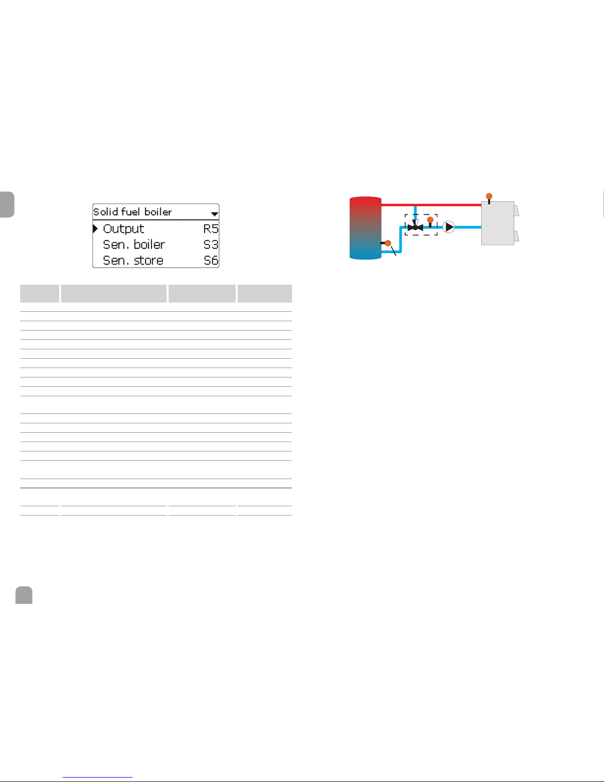
52
en
Solid fuel boiler
Arrangement / Opt. functions / Add new function / Solid fuel boiler
Adjustment
channel
Description
Adjustment range /
selection
Factory setting
Output Output selection system dependent system dependent
Sen. boiler Solid fuel boiler sensor selection system dependent system dependent
Sen. store Store sensor selection system dependent system dependent
DTo n Switch-on temperature difference 2.0 … 30.0 K 6.0 K
DToff Switch-off temperature difference 1.0 … 29.0 K 4.0 K
DTset Set temperature difference 3.0 … 40.0 K 10.0 K
TStoremax Maximum temperature 10 … 95 °C 60 °C
Tmin boiler Minimum temperature 10 … 95 °C 60 °C
Target temp. Target temperature option Yes, No No
Target temp. Target temperature 30 … 85 °C 65 °C
Sensor
Target temperature reference
sensor
system dependent system dependent
Mixer Mixer option Yes, No No
Mixer closed Output selection mixer closed system dependent system dependent
Mixer open Output selection mixer open system dependent system dependent
Sensor Mixer sensor allocation system dependent system dependent
DTopen Temperature difference mixer open 0.5 … 30.0 K 5.0 K
DTclosed
Temperature difference mixer
closed
0.0 … 29.5 K 2.0 K
Interval Mixer interval 1 … 20 s 4 s
Funct. Activation / Deactivation
Activated, Deactivated,
Switch
Activated
Sensor Switch input selection - -
Save / Delete
function
Save or delete function - -
optional
Boiler sensor
Store sensor
Output
Mixer sensor
The Solid fuel boiler function can be used for transferring heat from a solid fuel
boiler to a store.
The allocated output is energised when all switch-on conditions are fullled:
• the temperature difference between the allocated sensors has exceeded the
switch-on temperature difference
• the temperature difference between the allocated sensors has not fallen below
the switch-off temperature difference
• the temperature at the solid fuel boiler sensor has exceeded the minimum
temperature
• the temperature at the store sensor is below the maximum temperature
• one of the adjusted time frames is active (if the Timer option is selected)
When the Set temperature difference is exceeded, pump speed control starts.
For every deviation by 1 / 10 of the adjusted rise value, the pump speed will be
adjusted by 1 %.
If the Target temperature option is activated, the pump speed control logic will
change. The controller will remain at the minimum pump speed until the temperature at the allocated Sensor exceeds the adjusted Target temperature.
The Mixer option can be used to keep the boiler return temperature above Tmin
boiler. The mixer will be controlled with the adjustable Interval.

53
en
Circulation
Arrangement / Opt. functions / Add new function / Circulation
Adjustment
channel
Description Adjustment range / selection Factory setting
Output Output selection system dependent system dependent
Type Variant
Demand, Thermal, Timer,
Therm.+Timer, Demand+-
Timer
Thermal
Sensor Circulation sensor selection system dependent system dependent
To n Switch-on temperature 10 … 59 °C 40 °C
Toff Switch-off temperature 11 … 60 °C 45 °C
Timer Timer option Yes, No No
Delay Demand switch-on delay 0 … 3 s 0 s
Runtime Circulation pump runtime 01:00 … 15:00 min 03:00 min
Break time Circulation pump break time 10 … 60 min 30 min
Funct. Activation / Deactivation
Activated, Deactivated, Switch
Activated
Sensor Switch input selection - -
Save /
Delete
function
Save or delete function - -
Circulation
sensor
Output
The Circulation function can be used for controlling a circulation pump.
For the control logic, 5 variants are available:
• Thermal
• Timer
• Thermal + Timer
• Demand
• Demand + Timer
If one of the variants is selected, the corresponding adjustment channels will appear.
Thermal
The temperature at the allocated Sensor is monitored. The allocated Output
switches on when the temperature falls below the adjusted Switch-on tem-
perature. If the temperature exceeds the Switch-off temperature, the output
switches off.
Timer
The output switches on during the adjusted time frames, outside of them it switches off.
Thermal + Timer
The output operates when the switch-on conditions of both above-mentioned variants are fullled.
Demand
The allocated ow switch is monitored for circuit continuity. If circuit continuity is
detected at the ow switch, the output will switch on for the adjusted Runtime.
After the runtime has ended, the output switches off. During the adjusted Break
time, the output remains switched off even if continuity is detected at the ow
switch.
Demand + Timer
The output operates when the switch-on conditions of both above-mentioned
variants are fullled. When the Timer, Therm. + Timer or Demand + Timer
variant is activated, a timer is indicated in which time frames for the function can
be adjusted.
Note
If the ow switch is connected to the input S1 … S12, continuity must be
detected for at least 5 s for the controller to react, 1s if the ow switch is
connected to an impulse input.
Note
For information on timer adjustment see page 12.

54
en
Return preheating
Arrangement / Opt. functions / Add new function / Return preheat.
Adjustment
channel
Description
Adjustment range /
selection
Factory setting
Output Output selection system dependent
system dependent
Sen. return Return sensor selection system dependent
system dependent
Sen. source Heat source sensor selection system dependent
system dependent
DTo n
Switch-on temperature difference
2.0 … 30.0 K 6.0 K
DToff
Switch-off temperature difference
1.0 … 29.0 K 4.0 K
Summer off Summer switch-off option Yes, No No
Sensor Outdoor sensor selection system dependent
system dependent
Toff Switch-off temperature 10 … 60 °C 20 °C
Funct. Activation / Deactivation
Activated, Deactivated,
Switch
Activated
Sensor Switch input selection - -
Save / Delete
function
Save or delete function - -
Sensor
Source
Return
sensor
Output
The Return preheating function can be used for transferring heat from a heat
source to the heating circuit return.
The allocated output is energised when all switch-on conditions are fullled:
• the temperature difference between the allocated sensors has exceeded the
switch-on temperature difference
• the temperature difference between the allocated sensors has not fallen below
the switch-off temperature difference
• if Summer off is activated, the temperature at the outdoor temperature sensor
falls below the adjusted outdoor temperature value
With the Summer switch-off option, the return preheating can be suppressed
outside the heating period.

55
en
Function block
Arrangement / Opt. functions / Add new function / Function block
Adjustment
channel
Description
Adjustment range /
selection
Factory setting
Output Output selection system dependent system dependent
Thermostat a Thermostat a option Yes, No No
Th-a on Switch-on temperature thermostat a -40 … +250 °C +40 °C
Th-a off Switch-off temperature thermostat a -40 … +250 °C +45 °C
Sensor Sensor thermostat a system dependent system dependent
Thermostat b Thermostat b option Yes, No No
Th-b on Switch-on temperature thermostat b -40 … +250 °C +40 °C
Th-b off Switch-off temperature thermostat b -40 … +250 °C +45 °C
Sensor Sensor thermostat b system dependent system dependent
DT function Differential function Yes, No No
DTo n Switch-on temperature difference 1.0 … 50.0 K 5.0 K
DToff Switch-off temperature difference 0.5 … 49.5 K 3.0 K
DTset Set temperature difference 3 … 100 K 10 K
Sen. source Heat source sensor system dependent system dependent
Sen. sink Heat sink sensor system dependent system dependent
Timer Timer option Yes, No No
Ref. output Reference output option Yes, No No
Mode Reference output mode
OR, AND, NOR, NAND
OR
Output Reference output 1 all outputs -
Output Reference output 2 all outputs -
Output Reference output 3 all outputs -
Output Reference output 4 all outputs -
Output Reference output 5 all outputs -
Funct. Activation / Deactivation
Activated, Deactivated,
Switch
Activated
Sensor Switch input selection - -
Save / Delete
function
Save or delete function - -
In addition to the pre-dened optional functions, function blocks consisting of thermostat functions, timer, differential and reference output functions are available.
With the help of these function blocks, further components and functions respectively can be controlled.
To each function block, sensors and outputs available can be allocated. Sensors
already in use can be allocated again without impeding their control functions.
Within a function block the functions are interconnected (AND gate). This means
that the switching conditions of all the activated functions have to be fullled for
switching the allocated output. As soon as one condition is not fullled, the output
will switch off.
Thermostat function
The switching condition for the thermostat function is considered fullled when the
adjusted switch-on temperature (Th(x) on) is reached.
The switching condition for the thermostat function is considered unfullled when
the adjusted switch-off temperature (Th(x)off) is reached.
Allocate the reference sensor in the Sensor channel.
Adjust the maximum temperature limitation with Th(x)off > Th(x)on and the minimum temperature limitation with Th(x)on> Th(x)off. The temperatures cannot be
set to an identical value.
DT function
The switching condition for the DT function is considered fullled when the adjust-
ed switch-on temperature (DTon) is reached.
The switching condition for the DT function is considered unfullled when the
adjusted switch-off temperature (DToff) is reached.
The DT function is equipped with a speed control function. A set temperature dif-
ference and a minimum speed can be adjusted. The non-adjustable rise value is 2 K.
Reference output
Up to 5 Reference outputs can be selected. Whether the reference outputs are to
be switched in series (AND), in parallel (OR), in series + inverted (NAND) or in
parallel + inverted (NOR) can be adjusted in the Mode channel.
OR mode
If at least one of the reference outputs is switched on, the switching condition for
the reference output function is considered fullled.
If none of the reference outputs is switched on, the switching condition for the
reference output function is considered unfullled.
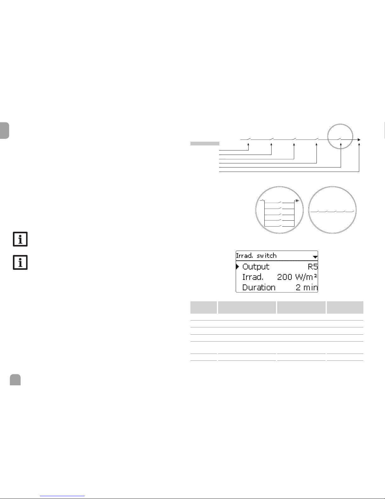
56
en
NOR mode
If none of the reference outputs is switched on, the switching condition for the
reference output function is considered fullled.
If at least one of the reference outputs is switched on, the switching condition for
the reference output function is considered unfullled.
AND mode
If all reference outputs are switched on, the switching condition for the reference
output function is considered fullled.
If at least one of the reference outputs is switched off, the switching condition for
the reference output function is considered unfullled.
NAND mode
If at least one of the reference outputs is switched off, the switching condition for
the reference output function is considered fullled.
If all reference outputs are switched on, the switching condition for the reference
output function is considered unfullled.
Note
If more than one function block has been activated, outputs of numerically
higher function blocks may not be used as reference outputs.
Note
For information on timer adjustment see page 12.
Function
Thermostat a
Tha- S3* Thb-S4* Timer R3*
RX
DT-S3>S4*
Thermostat b
DT function
Timer
Reference output
Reference
output
1. in parallel (OR) 2. in series (AND)
Reference output
Reference output 1
Reference output 1
Reference output 2
Reference output 2
Reference output 3
Reference output 3
Reference output 4
Reference output 4
Reference output 5
Reference output 5
* exemplary selection, sensors and outputs can be freely selected
Output
Irradiation switch
Arrangement / Opt. functions / Add new function / Irrad. switch
Adjustment
channel
Description
Adjustment range /
selection
Factory setting
Output Output selection system dependent system dependent
Irrad. Switch-on irradiation 50 … 1000 W/m² 200 W / m²
Duration Switch-on duration 0 … 30 min 2 min
Inverted Inverted switching option Yes, No No
Funct. Activation / Deactivation
Activated, Deactivated,
Switch
Activated
Sensor Switch input selection - -
Save / Delete
function
Save or delete function - -

57
en
The Irradiation switch function can be used for operating an output depending
on the measured irradiation value.
The allocated Output will be switched on if the adjusted irradiation value remains
exceeded for the adjusted Duration. If the irradiation falls below the adjusted irra-
diation value for the adjusted duration, the output will be switched off.
If the Inverted option is activated, the output will operate vice versa.
Return mixing function
Arrangement / Opt. functions / Add new function / Ret. mixing
Adjustment channel Description
Adjustment range
/ selection
Factory setting
Mixer open Output selection mixer open system dependent system dependent
Mixer closed Output selection mixer closed system dependent system dependent
Sen. store Store sensor allocation system dependent system dependent
Sen. HC ret. HC return sensor allocation system dependent system dependent
Sen. boiler ret. Boiler return sensor allocation system dependent system dependent
DTo n Switch-on temperature difference 1.0 … 25.0 K 5.0 K
DToff Switch-off temperature difference 0.5 … 24.0 K 3.0 K
DTset Set temperature difference -20 … +25 K +7 K
Tmax
Maximum boiler return temperature
10 … 80 °C 60 °C
Interval Mixer interval 1 … 20 s 2 s
HC intern.
Detection controller heating
circuit active
Yes, No No
HC intern. Heating circuit allocation HC1 … HC7 -
Runtime Mixer runtime 10 … 600 s 105 s
Time Time of automatic adjustment 00:00 … 23:45 00:00
Funct. Activation / Deactivation
Activated, Deactivated, Switch
Activated
Sensor Switch input selection - -
Save / Delete
function
Save or delete function - -
The Return mixing function can be used for heating backup.
Heat from the store is mixed into the heating circuit return by means of a mixing
valve in order to add heat to the heating circuit. The controller compares the temperature in the centre of the store to the heating circuit return temperature. If the
store temperature exceeds the heating circuit return temperature by the Switch-
on temperature difference, the mixer will be used to add heat from the store to
the heating circuit return. The mixer will be opened or closed in pulses depending
on this deviation. The mixer will be controlled with the adjustable Interval. The
pause is determined by the difference between the actual value and the set value.
Thus, the heating circuit return temperature is increased by the DTset value. The
adjustable Maximum boiler return temperature limits the mixing temperature. If the store temperature falls below the heating circuit return temperature by
the Switch-off temperature difference, the mixer will close.
If the mixing temperature exceeds Tmax by more than 5 K, a message will appear
in the status menu.
The Runtime denes the time needed for the mixer to switch from its initial posi-
tion to the end position. The Time denes the point in time when the mixer is set
to its initial or ending position respectively.
HC internal option
If the HC internal option is activated, the return mixing function will only become
active when a selectable heating circuit connected to the same controller is active,
too. For this purpose, the heating circuit selected has to be controlled by the con-
troller or by a module connected.
1: Sen. HC ret.
2: Sen. store
3: Sen. boiler ret.
1
2
3

58
en
10 HQM
In the HQM menu, up to 7 internal heat quantity measurements can be activated
and adjusted.
By selecting the menu item new HQM..., a new heat quantity measurement can
be activated.
A menu will open in which all adjustments required for the heat quantity measurement can be made.
If the Flow rate sensor option is activated, an impulse input or, if available, a
Grundfos Direct Sensor™ or a FlowRotor can be selected. The FlowRotor and
the Grundfos Direct Sensors™ will only be available if they have been previously
registered in the Inputs / Modules menu. The impulse rate must be adjusted in
that menu as well.
If the Flow rate sensor option is deactivated, the controller calculates the heat
quantity by means of a xed ow rate value.This is called heat quantity balancing.
For this purpose, the ow rate must be read from the owmeter at 100 % pump
speed and adjusted in the adjustment channel Flow rate. In addition to that, a
Relay must be allocated. Heat quantity balancing is in effect whenever the allocated
relay is active.
In the adjustment channel Fluid type, the heat transfer uid must be selected.
If either Propylene glycol or Ethylene glycol is selected, the adjustment channel
Concentration is indicated in which the antifreeze ratio of the heat transfer uid
can be adjusted.
If a calorimeter is being congured for the rst time or after the overall quantity
has been reset, the parameter Carryover will appear. A former value which is to
be added to the overall quantity, can be entered.
When the Alternative unit option is activated, the controller will convert the
heat quantity into the quantity of fossil fuels (coal, oil or gas) saved, or the CO
2
emission saved respectively. The alternative Unit can be selected. A Conversion
factor must be adjusted for the calculation. The conversion factor depends on the
arrangement in use and has to be determined individually.
Heat quantity measurements already saved will appear in the HQM menu above the
menu item new HQM… in numerical order.
If a heat quantity measurement already saved is selected, the above mentioned
submenu with all adjustment values will re-open.
At the end of each HQM submenu, the menu items Function and Save function
are available.
In order to save a heat quantity measurement, select Save function and conrm
the security enquiry by selecting Ye s . In heat quantity measurements already saved,
the menu item Delete function will appear instead.
In order to delete a heat quantity measurement already saved, select Delete function and conrm the security enquiry by selecting Ye s . The heat quantity measure-
ment deleted will disappear from the list and become available for selection in the
new HQM… menu again.

59
en
With the menu item Function, a heat quantity measurement already saved can be
temporarily deactivated or re-activated respectively. In this case, all adjustments will
remain stored.
By selecting Switch, the heat quantity measurement can be activated or deacti-
vated respectively by means of an external switch. If Switch is selected, the channel
Sensor will appear. In this channel, the sensor input to which the switch is to be
connected can be allocated to the function.
HQM / new HQM...
Adjustment
channel
Description
Adjustment range /
selection
Factory setting
Sen. ow Flow sensor selection system dependent system dependent
Sen. ret. Return sensor selection system dependent system dependent
Sen. ow rate
Flow rate sensor option
Yes, No No
Sen. ow rate Flow rate sensor selection
IMP1 … IMP3, Ga1, Ga2,
Gd1, Gd2, FR1
-
Fl.rate
Flow rate (only if Flow rate
sen. = No)
1.0 … 500.0 l/min 3.0 l/min
Relay Relay selection system dependent -
Fluid type Heat transfer uid
Tyfocor LS, Propylene
glycol, Ethylene glycol,
Water
Water
Concentr.
Glycol concentration in the
heat transfer uid (only if
uid type = propylene glycol
or ethylene glycol)
20 … 70 % 40 %
Alternative unit Alternative unit option Yes, No No
Carryover
Carryover value (for the rsttime conguration or after a
HQM reset only)
-
-
Unit Alternative display unit Coal, Gas, Oil, CO
2
CO
2
Factor Conversion factor 0.0000001 … 100.0000000 0.5000000
Funct. Activation / Deactivation Activated, Deactivated Activated
11 Basic settings
In the Basic settings menu, all basic parameters for the controller can be adjusted.
Normally, these settings have been made during commissioning. They can be subse-
quently changed in this menu.
Basic settings
Adjustment
channel
Description
Adjustment range /
selection
Factory setting
Language Selection of the menu
language
Deutsch, English,
Français, Italiano, Español,
Nederlands, Suomi
Deutsch
Auto DST Daylight savings time
selection
Yes, No Ye s
Date Adjustment of the date 01.01.2001 … 31.12.2099 01.01.2012
Time Adjustment of the current
time
00:00 … 23:59 -
Temp. unit Temperature unit °C, °F °C
Flow unit Volume unit Gallons, Litre Liter
Press. unit Pressure unit psi, bar bar
Energy unit Energy unit Wh, BTU Wh
Blocking pro-
tection
Blocking protection submenu - -
Start. time Blocking protection starting
time
00:00 … 23:59 12:00
Runtime Blocking protection runtime 1 … 30 s 10 s
Reset back to factory setting Yes, No No
Scheme Scheme selection 0000 … 9999 0000

60
en
12 SD card
The controller is equipped with an SD card slot for SD memory cards.
With an SD card, the following functions can be carried out:
• Logging measurement and balance values. After the transfer to a computer, the
values can be opened and visualised, e. g. in a spreadsheet.
• Store adjustments and parameterisations on the SD card and, if necessary, retrieve them from there.
• Running rmware updates on the controller.
Firmware updates
The current software can be downloaded from www.resol.com/rmware. When
an SD card with a rmware update is inserted, the enquiry Update? is indicated
on the display.
Î To run the update, select Yes and conrm by pressing button ➄.
The update will run automatically. The indication Please wait and a progress bar
will appear on the display. When the update has been completed, the controller will
automatically reboot and run a short initialisation phase.
Note
Only remove the card when the initialisation phase has been completed
and the main menu is indicated on the controller display!
Î To skip the update, select No.
The controller starts normal operation.
Note
The controller will only recognise a rmware update le if it is stored in a
folder named RESOL/HCMX on the rst level of the SD card.
ÎCreate a folder named RESOL/HCMX on the SD card and extract
the downloaded ZIP le into this folder.
Starting the logging
Î Insert the SD card into the slot.
Î Adjust the desired logging type and interval.
Logging will start immediately.
Completing the logging process
Î Select the menu item Remove card.
Î After Remove card is displayed, remove the card from the slot.
When Linear is adjusted in the logging type adjustment channel, data logging will
stop if the capacity limit is reached. The message Card full will be displayed.
If Cyclic is adjusted, the oldest data logged onto the SD card will be overwritten as
soon as the capacity limit is reached.
Note
Because of the increasing size of the data packets, the remaining logging
time does not decrease linearly. The data packet size can increase, e. g. with
the increasing operating hours value.
Controller adjustments, storing of
Î To store the controller adjustments on an SD card, select the menu item Save
adjustments.
While the adjustments are being stored, rst Please wait, then Done! will be
indicated on the display. The controller adjustments are stored as a .SET le on the
SD card.
Controller adjustments, loading of
Î To load controller adjustments from an SD card, select the menu item Load
adjustments.
The File selection window will appear.
Î Select the desired .SET le.
While the adjustments are being loaded, rst Please wait, then Done! will be
indicated on the display.
Note
To safely remove the SD card, always select the menu item Remove
card... before removing the card.

61
en
SD card
Adjustment channel Description
Adjustment range /
selection
Factory setting
Remove card... Safely remove card - -
Save adjustments Save adjustments - -
Load adjustments Load adjustments - -
Logging int. Logging interval 00:01 … 20:00 (mm:ss) 01:00
Logging type Logging type Cyclic, Linear Linear
13 Manual mode
In the Manual mode menu, the operating mode of all outputs in the controller and
in modules connected can be adjusted.
All outputs are displayed in numerical order, rst those of the controller, then those
of the individual modules connected. Modules are listed in numerical order.
In the All outputs... menu, all outputs can be switched off (Off) or set to automat-
ic mode (Auto) at once:
Off = Output is switched off (manual mode)
Auto = Output is in automatic mode
The operating mode can be selected for each individual output, too. The following
options are available:
Off = Output is switched off (manual mode)
On = Output is active at 100 % speed (manual mode)
Auto = Output is in automatic mode
Note
After service and maintenance work, the operating mode must be set back
to Auto. Normal operation is not possible in manual mode.
Manual mode
Adjustment
channel
Description
Adjustment range /
selection
Factory setting
Relay 1 … X Operating mode relay On, Auto, Off Auto
Output A … D Operating mode signal
output
On, Auto, Off Auto
Demand 1 (2) Operating mode demand Max, Auto, Min, Off Auto
all outputs Selection operating mode of
all relays
Auto, Off Off
14 User code
In the User code menu, a user code can be entered. Each number of the 4-digit
code must be individually adjusted and conrmed. After the last digit has been conrmed, the menu automatically jumps to the superior menu level.
To access the menu areas of the installer level, the installer user code must be
entered:
Installer: 0262
For safety reasons, the user code should generally be set to the customer code
before the controller is handed to the customer!
Customer: 0000

62
en
15 Inputs / Modules
In the Inputs / Modules menu, external modules can be registered and sensor
offsets be adjusted.
15.1 Modules
In this menu, up to 5 external modules can be registered.
All modules connected and acknowledged by the controller are available.
Î To register a module, select the corresponding menu item by pressing button
➄.
The checkbox indicates the selection. If a module is registered, all its sensor inputs
and relay outputs will be available in the corresponding controller menus.
Inputs / Modules / Modules
Adjustment
channel
Description
Adjustment range /
selection
Factory setting
Module 1 … 5 Registering external modules - -
15.2 Inputs
In this submenu, the type of the sensor connected can be adjusted for each individual input. The following types can be selected:
• S1 … S12: Switch, Fern (remote control), BAS (operating mode
switch), Pt1000, Pt500, KTY, None
• S13 / IMP1 … S15 / IMP3: Impulse, Switch, Fern (remote control), BAS (operating mode switch), Pt1000, Pt500, KTY, None
• CS10: A … K
• Ga1, Ga2: RPS, VFS, None
• Gd1, Gd2: RPD, VFD, None
• FR1: DN20, DN25, DN32, None
ATTENTION!
System damage!
Selecting the wrong sensor type will lead to unwanted control
behaviour. In the worst case, system damage can occur!
Î Make sure that the right sensor type is selected!
If KTY, Pt500 or Pt1000 is selected, the channel Offset appears, in which an
individual offset can be adjusted for each sensor.
Î In order to select a sensor for the offset adjustment, select the corresponding
menu item by pressing button ➄.
Î To adjust the sensor offset, select the desired value by pressing buttons❷ or
❹, then conrm by pressing button ➄.

63
en
Note
If a sensor is used as the temperature sensor of a function, the sensor
types Switch, Fern, BAS, Impulse and none will not be available for the
corresponding input.
ATTENTION!
Damage to the device!
Sensor inputs which have been set to the sensor type switch can
only be used for connecting potential-free switches.
Î Make sure no voltage is applied!
If switch is selected, the inverted option will appear and can be used for inverting
the behaviour of the switch.
CS sensor offset
If a CS10 irradiation sensor is to be connected, an offset has to be carried out
before the connection is made.
To carry out the offset, proceed as follows:
Î Adjust the CS type in the Type channel.
Î Select the Offset channel.
Î Conrm the Reset? enquiry with Ye s .
Î Select back to return to the Inputs menu, then connect the CS sensor.
Note
When Grundfos Direct Sensors
TM
are used, connect the sensor ground
common terminal block to PE (see page 7).
Inputs / Modules / Inputs
Adjustment
channel
Description
Adjustment range /
selection
Factory setting
S1 … S12 Sensor input selection - -
Type Sensor type selection
Switch, Fern, BAS, KTY,
Pt500, Pt1000, None
Pt1000
Offset Sensor offset -15.0 … +15.0 K 0.0 K
IMP1 …
IMP3
Impulse input selection - -
Type Sensor type selection
Impulse, Switch, Fern, BAS,
KTY, Pt500, Pt1000, None
Impulse
Inverted
Switch inversion (only when
Type = Switch)
Yes, No No
Adjustment
channel
Description
Adjustment range /
selection
Factory setting
Vol./Imp.
Impulse rate 0.1 … 100.0 l 1.0 l
CS10 CS10 input - -
Type CS type A … K E
Offset Delete offset Yes, No No
Ga1, 2
Analogue Grundfos Direct
Sensor
TM
1, 2
- -
Type Grundfos-Direct-Sensor
TM
type RPS, VFS, None None
Max.
Maximum pressure (if Type =
RPS)
0.0 … 16.0 bar 6 bar
Min.
Minimum ow rate
(if Type = VFS)
1 … 399 l/min 2 l/min
Max.
Maximum ow rate
(if Type = VFS)
2 … 400 l/min 40 l/min
Gd1, 2
Digital Grundfos Direct Sen-
sor
TM
1, 2
- -
Type Grundfos-Direct-Sensor
TM
type RPD, VFD, None None
if Type = VFD:
Measuring range selection
10 - 200 l/min, 5 - 100 l/min,
2 - 40 l/min, 2 - 40 l/min (fast),
1 - 20 l/min, 1 - 12 l/min*
1 - 12 l/min
* For the Inputs Gd1 and Gd2, the following sensor combinations are possible:
- 1 x RPD, 1 x VFD
- 2 x VFD, but with different measuring ranges only

64
en
Directional pad ashes red.
Sensor fault. The message !Sensor fault instead of a temperature is shown
on the sensor display channel.
The display is permanently off.
Press button ➄. Display illuminated?
no
yes
Controller has been in
standby, everything OK
Check the supply line and reconnect it.
The fuse of the controller could
be blown. The fuse holder (which
holds the spare fuse) becomes
accessible when the cover is
removed.The fuse can then be
replaced.
Check the power supply of the controller. Is it disconnected?
no yes
°C °F Ω
Pt500ΩPt1000
Ω
KTY
°C °F Ω
Pt500ΩPt1000
Ω
KTY
-10 14 481 961 1499 55 131 607 1213 2502
-5 23 490 980 1565 60 140 616 1232 2592
0 32 500 1000 1633 65 149 626 1252 2684
5 41 510 1019 1702 70 158 636 1271 2778
10 50 520 1039 1774 75 167 645 1290 2874
15 59 529 1058 1847 80 176 655 1309 2971
20 68 539 1078 1922 85 185 664 1328 3071
25 77 549 1097 2000 90 194 634 1347 3172
30 86 559 1117 2079 95 203 683 1366 3275
35 95 568 1136 2159 100 212 693 1385 3380
40 104 578 1155 2242 105 221 702 1404 3484
45 113 588 1175 2327 110 230 712 1423 3590
50 122 597 1194 2413 115 239 721 1442 3695
Short circuit or line break.
Disconnected temperature sensors can be checked with an ohmmeter. Please
check if the resistance values correspond with the table.
If a malfunction occurs, a message will appear on the display of the controller.
WARNING!
Electric shock!
Upon opening the housing, live parts are exposed!
Î Always disconnect the device from power supply be-
fore opening the housing!
The controller is protected by a fuse. The fuse holder (which also holds the spare
fuse) becomes accessible when the cover is removed. To replace the fuse, pull the
fuse holder from the base.
Note
For answers to frequently asked questions (FAQ) see www.resol.com.
16 Troubleshooting
Fuse

65
en
Is the pump current enabled by
the controller?
Display illuminated?
If not, press button ➄. Display
illuminated again?
Does the pump start up in manual
operation?
The heating circuit pump does not work, although this is indicated on the
status display.
yes no
yes
There is no current; check fuses
/ replace them and check power
supply.
The adjusted temperature difference for starting the pump is too
high; choose a value which makes
more sense.
no
yesno
Stores cool down at night.
Sufcient store insulation?
yes no
Increase insulation.
Insulation close enough to the store?
yes no
Replace insulation or increase it.
Are the store connections insulated?
yes no
Insulate the connections.
Warm water outow upwards?
no yes
Change connection and let the water
ow sidewards or through a siphon
(downwards); less store losses now?
no yes
o.k.
Controller might be defective -
replace it.
Is the pump stuck?
Turn the pump shaft using a
screwdriver; now passable?
Pump is defective - replace it.
yes
no
Does the DHW circulation run
for a very long time?
no yes
Use the circulation pump with
timer and switch-off thermostat
(energy-efcient circulation).
Circulation pump and blocking
valve should be switched off for 1
night; less store losses?
yes no
Check whether the pumps of the
after-heating circuit run at night;
check whether the non-return
valve is defective; problem solved?
no
Check the non-return valve in
warm water circulation - o.k.
yes no
The gravitation circulation in the
circulation line is too strong; insert
a stronger valve in the non-return
valve or an electrical 2-port valve
behind the circulation pump; the
2-port valve is open when the pump
is activated, otherwise it is closed;
connect pump and 2-port valve
electrically in parallel; activate the
circulation again. Deactivate pump
speed control!
Clean or replace it.
Further pumps which are con-
nected to the store must also be
checked.

66
en
17 Accessories
DL3 Datalogger
For visualisation via VBus.net, incl. SD card, mains adapter,
network and VBus
®
cable.
DL2 Datalogger
For visualisation via VBus.net, incl. SD card and network
cable, mains adapter and VBus
®
cable pre-connected.
EM Extension Module
Sensor and relay Extension module with 5 outputs and
6 inputs
TS10 Dew point switch
For condensation detection in a heating circuit used for
cooling purposes.
VFS / RPS & VFD / RPD Grundfos Direct Sensors
TM
Analogue / digital sensors in different versions
V40 Flowmeter
The V40 is a measuring instrument for detecting the ow
of water or water/glycol mixtures.
AM1 Alarm module
Alarm module for signalling system failures
SDFK Smart Display
The SDFK Smart Display indicates the solid fuel boiler
temperature and the bottom/top store temperatures as
well as the pump status.
SP10 Overvoltage protection device
Overvoltage protection device, suitable for mounting outdoors.
VBus
®
/ USB & VBus® / LAN interface adapters
With the VBus
®
/ USB interface adapter, the controller
can be connected to the USB port of a PC via the VBus®.
The VBus
®
/ LAN interface adapter is designed for the
direct connection of the controller to a PC or router.
It enables easy access to the controller via the local
network of the owner.
Sensors
The product range includes high-precision platinum tem-
perature sensors, atscrew sensors, outdoor temperature
sensors, indoor temperature sensors, cylindrical clip-on
sensors, also as complete sensors with immersion sleeve.

67
en
VBus®Touch HC
This easy-to-use app enables you to make adjustments on
your RESOL heating controller from a mobile device.
Thus, e. g. the operating mode can be set via the app.
Additionally, the system data are displayed in a clearly
arranged graphic.
VBus® is a registered trademark of RESOL GmbH
Google Play is a trademark of Google Inc.
Apple, the Apple logo, iPad, and iPhone are trademarks of Apple Inc., registered in the U.S. and other countries. App Store is a service mark of Apple Inc.

68
en
18 Index
0-10 V boiler control .......................................................................................................... 36
A
Antifreeze function ............................................................................................................. 41
App ....................................................................................................................................... 40
B
Backup heating, heating circuit ......................................................................................... 40
Boiler control ....................................................................................................................... 34
C
Chimney sweeper function ............................................................................................... 41
Circulation ............................................................................................................................ 53
Commissioning menu ......................................................................................................... 19
Condensation detection .................................................................................................... 42
Controller adjustments, loading of .................................................................................. 60
Controller adjustments, storing of .................................................................................. 60
Cooling via the heating circuit ......................................................................................... 42
Correction modes .............................................................................................................. 41
Countdown .......................................................................................................................... 41
D
Data logging .......................................................................................................................... 60
Day correction ..................................................................................................................... 37
Day/Night operation .......................................................................................................... 39
Day operation ...................................................................................................................... 41
Dew point switch ................................................................................................................ 42
DHW heating ....................................................................................................................... 46
DHW preheating ................................................................................................................ 47
DHW priority, heating circuit .......................................................................................... 41
E
Electrical connection ............................................................................................................ 7
Energy saving operation, heating circuit ......................................................................... 42
Error messages .................................................................................................................... 34
Error messages, acknowledgement of ............................................................................ 34
Error relay............................................................................................................................. 51
F
Function block ..................................................................................................................... 55
Fuse, replacing of ................................................................................................................. 64
H
Heat dump, heating circuit ................................................................................................ 42
Heating circuit mixer .......................................................................................................... 36
Heating circuit pump .......................................................................................................... 36
Heating curve ....................................................................................................................... 37
Heat quantity measurement ............................................................................................. 58
I
Interval................................................................................................................................... 36
Irradiation switch ................................................................................................................ 56
M
Manual mode ........................................................................................................................ 61
Maximum ow temperature ............................................................................................. 37
Minimum ow temperature .............................................................................................. 37
Mixer, optional arrangement function ............................................................................ 50
Mixer runtime ...................................................................................................................... 36
Modulating heating control ............................................................................................... 36
Modules, registration of ..................................................................................................... 62
Mounting ................................................................................................................................. 5
N
Night correction ................................................................................................................. 37
Night operation ................................................................................................................... 39
O
Offset ..................................................................................................................................... 62
Operating mode, outputs .................................................................................................. 61
Operating mode switch ..................................................................................................... 40
Output selection ................................................................................................................. 16

69
en
R
Registering external modules ........................................................................................... 62
Remote access, heating circuit ......................................................................................... 40
Remote control ............................................................................................................ 37, 40
Return mixing function ...................................................................................................... 57
Return preheating ............................................................................................................... 54
Room control, heating circuit ........................................................................................... 38
Room control unit .............................................................................................................. 40
Room inuence, heating circuit ........................................................................................ 37
Room thermostat ............................................................................................................... 38
S
Screed drying ....................................................................................................................... 47
Sensor offset ........................................................................................................................ 62
Set ow temperature ......................................................................................................... 37
Shared relays ........................................................................................................................ 34
Solid fuel boiler .................................................................................................................... 52
Special operation, heating circuit ..................................................................................... 42
Starting time ......................................................................................................................... 41
Start temperature ............................................................................................................... 48
T
Technical data ......................................................................................................................... 4
Thermal disinfection ........................................................................................................... 45
Thermostat function .......................................................................................................... 55
Timer ..................................................................................................................................... 12
U
User code ............................................................................................................................. 61
V
VBus ......................................................................................................................................... 8
Virtual .................................................................................................................................... 34
Z
Zone loading ........................................................................................................................ 50

70
en

71
en

Distributed by:
RESOL – Elektronische Regelungen GmbH
Heiskampstraße 10
45527 Hattingen / Germany
Tel.: +49 (0) 23 24 / 96 48 - 0
Fax: +49 (0) 23 24 / 96 48 - 755
www.resol.com
info@resol.com
Important note
The texts and drawings in this manual are correct to the best of our knowledge. As
faults can never be excluded, please note:
Your own calculations and plans, under consideration of the current standards and
directions should only be basis for your projects. We do not offer a guarantee for
the completeness of the drawings and texts of this manual - they only represent
some examples. They can only be used at your own risk. No liability is assumed for
incorrect, incomplete or false information and / or the resulting damages.
Note
The design and the specications can be changed without notice.
The illustrations may differ from the original product.
Imprint
This mounting- and operation manual including all parts is copyrighted. Another
use outside the copyright requires the approval of RESOL – Elektronische
Regelungen GmbH. This especially applies for copies, translations, micro lms
and the storage into electronic systems.
© RESOL – Elektronische Regelungen GmbH
 Loading...