


RESOL D e lt a S o l® ES
en
Mounting
Connection
Operation
Troubleshooting
Application examples
ES
®
Thanks for buying a RESOL product.
Read this manual carefully to get the best performance from this unit.
*48000770*
48000770
Please keep this manual carefully.
D e lt a S o l
manual
www.resol.com

D e lt a S o l® ES
Safety advice
Please pay attention to the following safety advice in order
to avoid danger and damage to people and property.
Instructions:
Attention should be paid to
• valid local regulations
• respective valid standards and directives
These instructions are exclusively addressed to authorised
skilled personnel.
• Only qualified electricians should carry out installation
and maintenance work.
• Initial installation should be carried out by qualified
personnel
Subject to change. Errors excepted.
Table of contents
Description of symbols .......................................................2
Information about the product ..........................................2
Disposal ................................................................................2
Overview ..............................................................................3
Technical data ......................................................................3
1. Installation .............................................................4
1.1 Mounting .................................................................................. 4
1.2 Electrical connection ............................................................. 4
1.2.1 Connection survey ................................................................ 4
1.2.2 Actuators ................................................................................. 5
1.2.3 Bus ............................................................................................. 5
1.2.4 Sensors ..................................................................................... 6
1.2.5 Power connection .................................................................. 6
2 Operation and function ........................................7
2.1 Adjustment buttons .............................................................. 7
2.2 System monitoring display ................................................... 7
2.2.1 Channel display ....................................................................... 7
2.2.2 Tool bar .................................................................................... 7
2.2.3 System screen ......................................................................... 8
2.3 Flashing codes ......................................................................... 8
2.3.1 System screen flashing codes .............................................. 8
2.3.2 Operating control lamp flashing codes ............................. 8
3. Commissioning ......................................................9
4. Control parameter and display channels ..........10
4.1 Channel overview ................................................................ 10
4.2.1-7 Display channels ................................................................... 18
4.3.1-15 Adjustment channels ...........................................................19
5. Troubleshooting ...................................................24
5.1 Various ...................................................................................25
6. Accessories ..........................................................27
Imprint ...............................................................................28
Description of symbols
WARNING!
Warnings are indicated with a
warning triangle!
Signal words describe the danger that may occur, when it
is not avoided.
• Warning means that injury, probably life-threatening
injury, can occur.
• Attention means that damage to the appliance can
occur.
Note
Notes are indicated with an information symbol.
Î Arrows indicate instruction steps that should be car-
ried out.
| 2
Information about the product
Proper usage
This product is to be used to control a solar thermal/heating
unit in compliance with the technical data specified in this
manual.
Improper use excludes all liability claims.
CE – Declaration of conformity
The product complies with the relevant directives and is therefore labelled with the CE mark.
The Declaration of Conformity is available upon
request, please contact RESOL.
Disposal
• Dispose of the packaging in an environmentally sound
manner.
• Dispose of old appliances in an environmentally sound
manner. Upon request we will take back your old appliances bought from us and guarantee environmentally
friendly disposal of the devices.
© RESOL DeltaSol ES_09190.monen.indd

D e lt a S o l® ES
155,0
220,0
202,0
12,0
62,0
!
Overview
• 36 basic solar systems selectable
• illuminated system-monitoring
display
• pump speed control, solar operating hours counter and heat quantity measurement
• 10 sensor inputs
• 6 relay outputs
• function control
• VBus
®
© RESOL DeltaSol ES_09190.monen.indd
The D e lt a S o l
®
ES comes with
1 x accessory bag
2 x screws and wall plugs
4 x strain-relief and screws
1 x capacitor 4,7 nF
Additionally enclosed in the full kit:
2 x sensor FKP6
3 x sensor FRP6
Technical data
Housing: plastic, PC-ABS and PMMA
Protection type:
IP 20 / EN 60 529
Ambient temp.: 0 ... 40 °C
Size: 220 x 155 x 62 mm
Mounting: wall mounting, mounting
into patch-panels is possible
Display: multi-functional combined
display with illuminated background,
stored system schemes and pictograms,
a 4-digit alpha-numerical 16-segment
display and a 4-digit numerical 7-segment display as well as a bi-coloured
LED. The controller can optionally be
equipped with an illuminated 4-digit
LC-text display.
Operation: by 3 pushbuttons at the
front of the housing
The controller is pre-programmed
for 36 solar and heating systems, the
individual installation configuration
can be selected via the menu and
represented graphically via the systemmonitoring display. An integrated heat
quantity measurement, operating hours
counter and the newly developed
Functions: solar- and heating controller with pre-programmed and
selectable system schemes, such as:
standard solar system, 2-store systems,
east-/west collectors, heating circuit
back-up, heat exchange regulation, thermos tatic after-heating, solid fuel boilers,
add-on functions and options just as
heat quantity measurement, collector
cooling function, tube collector special
function, anti-freeze function, minimum
tempe ra ture limitation, pump speed
control, measurement of heat quantity
output, func tion control.
Sensor inputs:
8 x Pt1000
1 x CS10
1 x V40
system-monitoring display allows a
clear visualisation of the system. For
da ta commu ni ca ti on and rem ot e
service, the controller is equipped
with RESOL VBus
®
which opens the
bi-directional way to modules, PCs or
for data logging.
Relay outputs: 6 relay outputs, 3 of
them for pump speed control
Bus: VBus
®
Power supply: 220 … 240 V~
Power input:
Standby: 3,11 W
Full load: 5,57 W
Switching capacity:
4 (1) A (220 … 240) V~
Rated impulse voltage: 2,5 kV
Mode of operation: Typ 1.b / Typ 1.y
Degree of pollution 2
3 |

D e lt a S o l® ES
1. Installation
1.1 Mounting
locking screw
cover
135 mm
Push Push - locking device
push to open
push to close
upper fastening
display
pushbutton
can fuse T4A
144 mm
WARNING!
Always switch off power supply and
disconnect the controller from the
mains before opening the housing!
The unit must only be located in dry interior locations. It
is not suitable for installation in hazardous locations and
should not be placed close to any electromagnetic fields. The
controller must additionally be supplied from a double-pole
switch with contact gap of at least 3 mm. Please pay attention to separate routing of sensor cables and mains cables.
Î Open the front cover by pushing it. Unscrew the cross-
head screw from the cover and remove it along with
the front cover from the housing.
Î Mark the upper fastening point on the wall and drill
and fasten the enclosed wall plug and screw leaving the
head protruding.
Î Hang the housing from the upper fastening point and
mark the lower fastening point through the hole in the
terminal box (centres 135 mm). Drill and insert the
lower wall plug.
Î Hang the housing from the upper fastening point and
attach with the lower screw.
Î Carry out connection in accordance with the terminal
allocation.
Î Insert cover and attach with the cross-head screw.
Close the front cover properly.
lower fastening
1.2 Electrical connection
1.2.1 Connection survey
sensor terminal
VBus
Electrostatic discharge can cause damages of electronic components
Attention: high-voltaged components
fuseT4 A
®
consumer terminals
mains terminal
| 4
sensor
terminal block
terminal block
ground wire terminal
block
© RESOL DeltaSol ES_09190.monen.indd

D e lt a S o l® ES
1.2.2 Actuators
(pumps, valves, etc.)
terminal block
ground wire terminal block
The controller is equipped with six relays in total, to which
loads (actuators) such as pumps, valves, mixers and auxiliary
relays can be connected:
• Relays R1 ... R3 are semiconductor relays, designed for
pump speed control.
R1 ... R3 = normally open R1 ... R3
N = neutral conductor N (terminal block)
PE = protective earth conductor PE
(terminal block)
• Relays R4 and R5 are electromechanical relays with
one shutter:
R4, R5 = normally open R4, R5
N = neutral conductor N (terminal block )
PE = protective earth conductor PE
(terminal block)
• Relay RP is a potential-free relay with change-over-
contact:
RP-M = centre contact RP
RP-A = normally open RP
RP-R = break contact RP
RP switches parallel to R3 in all systems with afterheating
(SYS 3, 10, 12, 15, 19, 22, 25, 28) to provide a boiler demand
if necessary.
1.2.3 Data communication / Bus
Note
The relays R1 up to R3 are semiconductor relays for pump speed control. A minimum load of
20 W (power consumption of the consumer) is
required for faultless function. The 4.7nF capacitor from the accessory bag must be connected
in parallel to the respective relay output if it
feeds auxiliary relays, motor valves, etc.
The minimum pump speed must be set to 100%
when auxiliary relays or valves are connected.
®
The controller comes with a RESOL VBus
for data
transfer with and energy supply to external modules. The
connection is carried out at the terminals marked „VBus“
(either polarity). One or more RESOL VBus® modules can
be connected via this data bus, e.g.:
• RESOL calorimeter WMZ
• RESOL large display GA3, smart display SD3
• RESOL Data logger, DL2
• RESOL Data remote display
®
VBus
connection terminals
Additionally, the controller can be connected to a PC with
a RESOL RS-COM adapter. With the RESOL ServiceCenter
Software (RSC) the controller parameters can be changed,
measurements can be read out, processed and visualised. It
allows easy function control and adjustment of the system.
The software can be downloaded for free at www.resol.com
© RESOL DeltaSol ES_09190.monen.indd
5 |

D e lt a S o l® ES
1.2.4 Sensors
earth terminal block
1.2.5 Mains supply
The controller is equipped with 10 sensor inputs in total.
The protective earth connection for sensors is effected by
the protective earth terminal block (GND).
• The temperature sensors are connected to the termi-
nals S1 ... S8 and GND with either polarity.
• A flowmeter RESOL V40 can be connected to the ter-
minals V40 and GND with either polarity.
• The irradiation sensor (CS10) is to be connected
to the terminals CS10 and GND with correct polarity.
Connect the terminal GND of the sensor to the terminal
GND of the controller, and the terminal CS of the sensor
to the terminal CS10 of the controller.
conductor L
The power supply to the controller must be carried out via
an external power switch (last step!) and the supply voltage
must be 220 ... 240 V~ (50 ... 60 Hz). Flexible cables must
be attached to the housing with the enclosed strain relief
and the corresponding screws or be run into the controller
housing in a cable conduit or trunking.
neutral conductor N (terminal block)
ground wire PE ( terminal block)
| 6
© RESOL DeltaSol ES_09190.monen.indd

D e lt a S o l® ES
2. Operation and function
2.1 Pushbuttons for adjustment
Operating control
lamp
(-) backwards
2
1
3
(selection / adjustment mode)
SET / OK
forward
The controller is operated via the 3 push buttons below the
display. The forward-button (1) is used for scrolling forward
through the display menu or to increase the adjustment values.
The backward-button (2) is similarly used for scrolling backwards and reducing values.
(+)
In order to access the adjustment mode, scroll down in the
display menu and press the forward button (1) for approx.
2 seconds after you have reached the last diplay item. If an
adjustment value is shown on the display, the ”SEt“ icon
is displayed. Now, you can access the adjustment mode by
using button 3.
Î Press buttons 1 and 2 in order to select a channel
Î Briefly press button 3, „SEt“ will flash
Î Adjust the value by pressing buttons 1 and 2
Î Briefly press button 3, so that SEt permanently ap-
pears, the adjusted value will be saved.
2.2 System monitoring display
!
total monitoring display
2.2.1 Channel display
channel display only
2.2.2 Tool bar
tool bar only
© RESOL DeltaSol ES_09190.monen.indd
The system monitoring display consists of three blocks:
channel display, tool bar and system screen (active
system scheme).
The channel display consists of two lines. The upper line is an
alpha-numeric 16-segment display (text display) for displaying
channel names and menu items. In the lower 7-segment
display, the channel values and the adjustment parameters
are displayed. Temperatures and temperature.
Temperatures and temperature differences are indicated in
°C or K respectively.
The additional symbols in the tool bar indicate the current
system status.
Symbol normal flashing
relay 1 active
relay 2 active
maximum store limitation
active / maximum store
temperature exceeded
antifreeze function active
+
+
collector cooling function
active
recooling function active
collector minimum limitation
active
antifreeze function active
collector emergency shutdown active or store emergency shutdown active
sensor defective
manual operation active
SET-mode
7 |

D e lt a S o l® ES
2.2.3 System screen
system screen only
The system screen (active arrangement) displays the scheme
which has been selected. The screen consists of several
system component symbols, which are - depending on the
current status of the system - either flashing, permanently
shown or „hidden“.
collector 1
valve
pump
sensors
store heat exchanger
Collectors
with collector sensor
Store 1 and 2
with heat exchanger
collector 2
store
sensor store top
heating circuit
valve
sensor
additional symbol
for operation of the
burner
store 2 or after-heating (with
additional symbol)
Temperature sensor
Heating circuit
Pump
3-port valve
The flow direction or the
actual switching position is
shown.
2.3 Flashing codes
2.3.1 System screen flashing codes
2.3.2 Operating control lamp flashing codes
| 8
After-heating
with burner symbol
• Pumps are flashing during starting phase
• Sensors are flashing if the respective sensor display
channel is selected.
• Sensors are flashing quickly in the case of a sensor
defect.
• Burner symbol is flashing if after-heating is activated.
green: everything OK
manual operation
red flashing: sensor fault
(sensor symbol is flashing quickly)
© RESOL DeltaSol ES_09190.monen.indd

D e lt a S o l® ES
3. Commissioning
Note
Select the system scheme when the controller is commissioned for the first time.
Select the system first, because the subsequent
selection of a new system will reset all other
adjustments to the factory settings!
Operating control
lamp
(-) backwards
2
(selection / adjustment mode)
3
SET
1. AC power supply must be activated. The controller passes
an initialisation phase in which the operating control lamp
flashes red and green. After having finished the initialisation, the controller is in automatic operation (factory
setting). The pre-adjusted system scheme is Arr 1.
2. Adjust the time in the adjustment channel TIME. By
pressing once the pushbutton the hours are shown
(flashing), by pressing again the minutes are shown (flashing).
The time can be adjusted by pushbuttons 1 and 2 and be
stored by a last pressing of the pushbutton .
3. Adjustment of the system scheme
Î select Arr
Î change into the
forward (+)
1
Î select system scheme by Arr-characteristics
Î adjustments are stored by pressing
4. If the solar sensor CS10 is used
-mode (see 2.1)
Î change into the -mode (see 2.1)
Î select CS10 type by characteristics
Î adjustments are stored by pressing
Î After the CS type has been set, carry out the CS ad-
justment. For this purpose, select the measured value
SOL. Press button 3 and hold it for 5 seconds. The
adjustment has to be carried out when it is dark or
when the solar cell is not connected.
Now the controller is ready for operation and should enable
an optimum operation of the solar system.
System 1
System 7 System 8
System 13 System 14 System 15
System 19 System 20
System 25
System 2 System 3 System 4 System 5
System 9
System 21 System 22 System 23 System 24
System 26
System 27 System 28
System 6
System 10
System 16 System 17 System 18
System 11 System 12
System 29 System 30
© RESOL DeltaSol ES_09190.monen.indd
System 31 System 32 System 33 System 34
System 35
System 36
9 |

D e lt a S o l® ES
4. Controller parameters and adjustment channels
4.1 Channel overview
Legend:
x
Corresponding channel is available.
x*
Corresponding channel is available if the corresponding
option is activated.
Note
The channels S3 and S4 are only displayed when
there are sensors connected to the respective
terminals.
Channel survey: Systems Arr 1 ... 10
Chan-
nel
COL x x x x x x x x x Collector temperature 1
COL 1 x Collector temperature 1
TSTL x x x x x x x Store temperature lower
TST1 x x x Store temperature 1 lower
TSTU x x x x x x x x x x Store temperature 1 at the top
S4 Store temperature at the middle
TST2 x x x Store temperature 2 lower
TFSB x Temperature solid fuel boiler
TRET x x Temperature heating curcuit
COL2 x Collector temperature 2
TFL
TRF
IRR x x x x x x x x x x Solar irradiation intensity
n % x x x x Pump speed relay
n1 % x x x x x x Pump speed relay 1
n2 % x x Pump speed relay 2
n3% x x x x Pump speed relay 3
hP x x x x Hours of operation relay 1
h P1 x x x x x x Hours of operation relay 1
h P2 x x Hours of operation relay 2
h P3 x x x x Hours of operation relay 3
FLOW
kWh
MWh
TIME x Time
Arr 1-36 System
DT O x x x x x x x Switch-on temperature difference
DT1O x x x Switch-on temperature difference 1
DT F x x x x x x x Switch-off temperature difference 1
DT1F x x x Switch-off temperature difference 1
DT S x x x x x x x Set temperature difference
DT1S x x x Set temperature difference 1
RIS x x x x x x x Rise
RIS1 x x x Rise 1
S MX x x x x x x x Maximum store temperature 1
S1 MX x x x Maximum store temperature 1
DT2O x x x Switch-on temperature difference 2
DT2F x x x Set temperature difference 2
DT2S x x x Set temperature difference 2
RIS2 x x x Rise 2
S2MX x x x Maximum store temperature 2
EM x x x x x x x x x Emergency collector temperature 1
EM1 x Emergency collector temperature 1
1 2 3 4 5 6 7 8 9 10
| 10
Arr
Corresponding channel is only available if the option heat
quantity measurement is activated (OHQM).
MEDT
Only if an antifreeze type (MEDT) other than water or Ty-
focor LS / G-LS (MEDT 0 or 3) is used, will the channel
antifreeze concentration (MED%) be displayed
Description
Temperature flow sensor
Temperature return sensor
Flow rate
Heat quantity kWh
Heat quantity MWh
© RESOL DeltaSol ES_09190.monen.indd

D e lt a S o l® ES
Chan-
nel
OCX x x x x x x x x x Option Collector cooling collector 1
OCX1 x Option Collector cooling collector 1
CMX x* x* x* x* x* x* x* x* x* Maximum collector temperature 1
CMX1 x* Maximum collector temperature 1
OCN x x x x x x x x x Option min. limitation collector 1
OCN1 x Option min. limitation collector 1
CMN x* x* x* x* x* x* x* x* Minimum temperature collector 1
CMN1 x* Minimum temperature collector 1
OCF x x x x x x x x x Option antifreeze collector 1
OCF1 x Option antifreeze collector 1
CFR x* x* x* x* x* x* x* x* x* Antifreeze temperature collector 1
CFR1 x* Antifreeze temperature collector1
EM2 x Emergency temperature collector 2
OCX2 x Option collector cooling collector 2
CMX2 x* Maximum temperature collector 2
OCN2 x Option min. limitation collector 2
CMN2 x* Minimum temperature collector 2
OCF2 x Option antifreeze collector 2
CFR2 x* Antifreeze temperature collector 2
PRIO x x x Priority
tSP x x x Stop time
tRUN x x x Circulation
OREC x x x x x x x x x x Option recooling
O TC x x x x x x x x x x Option tube collector
DT3O x x x Switch-on temperature difference 3
DT3F x x x Switch-off temperature difference 3
DT3S x x Set temperature DT3
RIS3 x x Rise DT3
MX3O x x Switch-on step max. temperature
MX3F x x Switch-off step max. temperature
MN3O x x Switch-on step min. temperature
MN3F x x Switch-off step min. temperature
AH O x x Switch-on temperature thermostat
AH F x x Switch-off temperature thermostat
t1 E x x Switch-on time 1 thermostat
t1 A x x Switch-off time 1 thermostat
t2 E x x Switch-on time 2 thermostat
t2 A x x Switch-off time 2 thermostat
t3 E x x Switch-on time 3 thermostat
t3 A x x Switch-off time 3 thermostat
OHQM x x x x x x x x x x Option HQM
VIMP
MEDT
MED % MEDT MEDT MEDT MEDT MEDT MEDT MEDT MEDT MEDT MEDT Antifreeze concentration
CS 10 x x x x x x x x x x Solar cell
n MN x x x x Minimum pump speed relay 1
n1MN x x x x x x Minimum pump speed relay 1
n2MN x x Minimum pump speed relay 2
n3MN x x Minimum pump speed relay 3
MAN1 x x x x x x x x x x Manual operation relay 1
MAN2 x x x x x x x x x x Manual operation relay 2
MAN3 x x x x x x x x x x Manual operation relay 3
MAN4 x x x x x x x x x x Manual operation relay 4
MAN5 x x x x x x x x x x Manual operation relay 5
MAN6 x x x x x x x x x x Manual operation relay 6
LANG x x x x x x x x x x Language
PROG XX.XX Programme version
© RESOL DeltaSol ES_09190.monen.indd
VERS X.XX Version
1 2 3 4 5 6 7 8 9 10
Arr
Description
Impulse rate flowmeter
Antifreeze
11 |

D e lt a S o l® ES
Channel survey: Systems Arr 11 ... 20
Chan-
nel
COL
COL 1
TSTL
TST1
TSTU
S4 Store temperature at the middle
TST2
TFSB
TRET
COL2
TFL
TRF
IRR
n %
n1 %
n2 %
n3%
hP
h P1
h P2
h P3
FLOW
kWh
MWh
TIME
Arr
DT O
DT1O
DT F
DT1F
DT S
DT1S
RIS
RIS1
S MX
S1 MX
DT2O
DT2F
DT2S
RIS2
S2MX
EM
EM1
11 12 13 14 15 16 17 18 19 20
x x x x x x x
x x x x x x
x
x x x x x x x x x x
x x x x
x x
x x
x x x x x x x x x x
x
x x x x x x x x x
x x x x x x x x x
x
x x x x x x x x x
x x x x x x x x x
x x x x x x x
x x x x x x x
x x x x x x x
x x x x x x x
x x x x x x x
x x x x x x x
x x x x x x x
x x x x x x x
x x x x x x x
x x x x x x x
x x x x x x x
Arr
x
1-36
x x x
x x x
x x x x
x x x x
x x x
x x x
x x x
x x x
x x x
x x x
Description
Collector temperature 1
Collector temperature 1
Store temperature lower
Store temperature 1 lower
Store temperature 1 at the top
Store temperature 2 lower
Temperature solid fuel boiler
Temperature heating circuit
Collector temperature 2
Temperature flow sensor
Temperature return sensor
Solar irradiation intensity
Pump speed relay
Pump speed relay 1
Pump speed relay 2
Pump speed relay 3
Hours of operation relay 1
Hours of operation relay 1
Hours of operation relay 2
Hours of operation relay 3
Flow rate
Heat quantity kWh
Heat quantity MWh
Time
System
Switch-on temperature difference
Switch-on temperature difference 1
Switch-off temperature difference 1
Switch-off temperature difference 1
Set temperature difference
Set temperature difference 1
Rise
Rise 1
Maximum store temperature 1
Maximum store temperature 1
Switch-on temperature difference 2
Set temperature difference 2
Set temperature difference 2
Rise 2
Maximum store temperature 2
Emergency collector temperature 1
Emergency collector temperature 1
| 12
© RESOL DeltaSol ES_09190.monen.indd

D e lt a S o l® ES
Chan-
nel
OCX x x x x x x x Option Collector cooling collector 1
OCX1 x x x Option Collector cooling collector 1
CMX x* x* x* x* x* x* x* Maximum collector temperature 1
CMX1 x* x* x* Maximum collector temperature 1
OCN x x x x x x x Option min. limitation collector 1
OCN1 x x x Option min. limitation collector 1
CMN x* x* x* x* x* x* x* Minimum temperature collector 1
CMN1 x* x* x* Minimum temperature collector 1
OCF x x x x x x x Option antifreeze collector 1
OCF1 x x x Option antifreeze collector 1
CFR x* x* x* x* x* x* x* Antifreeze temperature collector 1
CFR1 x* x* x* Antifreeze temperature collector1
EM2 x x x Emergency temperature collector 2
OCX2 x x x Option collector cooling collector 2
CMX2 x* x* x* Maximum temperature collector 2
OCN2 x x x Option min. limitation collector 2
CMN2 x* x* x* Minimum temperature collector 2
OCF2 x x x Option antifreeze collector 2
CFR2 x* x* x* Antifreeze temperature collector 2
PRIO x x x x x x x Priority
tSP x x x x x x x Stop time
tRUN x x x x x x x Circulation
OREC x x x x x x x x x x Option recooling
O TC x x x x x x x x x x Option tube collector
DT3O x x x x x x x x Switch-on temperature difference 3
DT3F x x x x x x x x Switch-off temperature difference 3
DT3S
RIS3 x x x x x x Rise DT3
MX3O x x x x x x Switch-on step max. temperature
MX3F x x x x x x Switch-off step max. temperature
MN3O x x x x x x Switch-on step min. temperature
MN3F x x x x x x Switch-off step min. temperature
AH O x x x Switch-on temperature thermostat
AH F x x x Switch-off temperature thermostat
t1 E x x x Switch-on time 1 thermostat
t1 A x x x Switch-off time 1 thermostat
t2 E x x x Switch-on time 2 thermostat
t2 A x x x Switch-off time 2 thermostat
t3 E x x x Switch-on time 3 thermostat
t3 A x x x Switch-off time 3 thermostat
OHQM x x x x x x x x x x Option HQM
VIMP
MEDT
MED % MEDT MEDT MEDT MEDT MEDT MEDT MEDT MEDT MEDT MEDT Antifreeze concentration
CS 10 x x x x x x x x x x Solar cell
n MN x Minimum pump speed relay 1
n1MN x x x x x x x x x Minimum pump speed relay 1
n2MN x x x x Minimum pump speed relay 2
n3MN x x x x x x Minimum pump speed relay 3
MAN1 x x x x x x x x x x Manual operation relay 1
MAN2 x x x x x x x x x x Manual operation relay 2
MAN3 x x x x x x x x x x Manual operation relay 3
MAN4 x x x x x x x x x x Manual operation relay 4
MAN5 x x x x x x x x x x Manual operation relay 5
MAN6 x x x x x x x x x x Manual operation relay 6
LANG x x x x x x x x x x Language
PROG XX.XX Programme version
VERS X.XX Version
© RESOL DeltaSol ES_09190.monen.indd
11 12 13 14 15 16 17 18 19 20
x x x x x x
Arr
Description
Set temperature DT3
Impulse rate flowmeter
Antifreeze
13 |

D e lt a S o l® ES
Channel survey: Systems Arr 21 ... 30
Chan-
nel
COL Collector temperature 1
COL 1 x x x x x x x x x x Collector temperature 1
TSTL x x x x x x x Store temperature lower
TST1 x x Store temperature 1 lower
TSTU x x x x x x x x x x Store temperature 1 at the top
S4 Store temperature at the middle
TST2 x x Store temperature 2 lower
TFSB x Temperature solid fuel boiler
TRET x x x x Temperature heating circuit
COL2 x x x x x x x x x x Collector temperature 2
TFL
TRF
IRR x x x x x x x x x x Solar irradiation intensity
n % Pump speed relay
n1 % x x x x x x x x x x Pump speed relay 1
n2 % x x x x x x x x x x Pump speed relay 2
n3% x x x x x x Pump speed relay 3
hP Hours of operation relay 1
h P1 x x x x x x x x x x Hours of operation relay 1
h P2 x x x x x x x x x x Hours of operation relay 2
h P3 x x x x x x x Hours of operation relay 3
FLOW
kWh
MWh
TIME x Time
Arr 1-36 System
DT O x x Switch-on temperature difference
DT1O x x x x x x x x Switch-on temperature difference 1
DT F x x Switch-off temperature difference 1
DT1F x x x x x x x x Switch-off temperature difference 1
DT S x x Set temperature difference
DT1S x x x x x x x x Set temperature difference 1
RIS x x Rise
RIS1 x x x x x x x x Rise 1
S MX x x x Maximum store temperature 1
S1 MX x x x x x x x x Maximum store temperature 1
DT2O x x x x x x x x Switch-on temperature difference 2
DT2F x x x x x x x x Set temperature difference 2
DT2S x x x x x x x x Set temperature difference 2
RIS2 x x x x x x x x Rise 2
S2MX x x x x x x x x Maximum store temperature 2
EM Emergency collector temperature 1
EM1 x x x x x x x x x x Emergency collector temperature 1
21 22 23 24 25 26 27 28 29 30
Arr
Description
Temperature flow sensor
Temperature return sensor
Flow rate
Heat quantity kWh
Heat quantity MWh
| 14
© RESOL DeltaSol ES_09190.monen.indd

D e lt a S o l® ES
Chan-
nel
OCX Option Collector cooling collector 1
OCX1 x x x x x x x x x x Option Collector cooling collector 1
CMX Maximum collector temperature 1
CMX1 x* x* x* x* x* x* x* x* x* x* Maximum collector temperature 1
OCN Option min. limitation collector 1
OCN1 x x x x x x x x x x Option min. limitation collector 1
CMN Minimum temperature collector 1
CMN1 x* x* x* x* x* x* x* x* x* x* Minimum temperature collector 1
OCF Option antifreeze collector 1
OCF1 x x x x x x x x x x Option antifreeze collector 1
CFR Antifreeze temperature collector 1
CFR1 x* x* x* x* x* x* x* x* x* x* Antifreeze temperature collector1
EM2 x x x x x x x x x x Emergency temperature collector 2
OCX2 x x x x x x x x x x Option collector cooling collector 2
CMX2 x* x* x* x* x* x* x* x* x* x* Maximum temperature collector 2
OCN2 x x x x x x x x x x Option min. limitation collector 2
CMN2 x* x* x* x* x* x* x* x* x* x* Minimum temperature collector 2
OCF2 x x x x x x x x x x Option antifreeze collector 2
CFR2 x* x* x* x* x* x* x* x* x* x* Antifreeze temperature collector 2
PRIO x x x x x x x x Priority
tSP x x x x x x x x Stop time
tRUN x x x x x x x x Circulation
OREC x x x x x x x x x x Option recooling
O TC x x x x x x x x x x Option tube collector
DT3O x x x x x x Switch-on temperature difference 3
DT3F x x x x x x x Switch-off temperature difference 3
DT3S
RIS3 x x x Rise DT3
MX3O x x x Switch-on step max. temperature
MX3F x x x Switch-off step max. temperature
MN3O x x x Switch-on step min. temperature
MN3F x x x Switch-off step min. temperature
AH O x x x Switch-on temperature thermostat
AH F x x x Switch-off temperature thermostat
t1 E x x x Switch-on time 1 thermostat
t1 A x x x Switch-off time 1 thermostat
t2 E x x x Switch-on time 2 thermostat
t2 A x x x Switch-off time 2 thermostat
t3 E x x x Switch-on time 3 thermostat
t3 A x x x Switch-off time 3 thermostat
OHQM x x x x x x x x x x Option HQM
VIMP
MEDT
MED % MEDT MEDT MEDT MEDT MEDT MEDT MEDT MEDT MEDT MEDT Antifreeze concentration
CS 10 x x x x x x x x x x Solar cell
n MN Minimum pump speed relay 1
n1MN x x x x x x x x x x Minimum pump speed relay 1
n2MN x x x x x x x x x x Minimum pump speed relay 2
n3MN x x x Minimum pump speed relay 3
MAN1 x x x x x x x x x x Manual operation relay 1
MAN2 x x x x x x x x x x Manual operation relay 2
MAN3 x x x x x x x x x x Manual operation relay 3
MAN4 x x x x x x x x x x Manual operation relay 4
MAN5 x x x x x x x x x x Manual operation relay 5
MAN6 x x x x x x x x x x Manual operation relay 6
LANG x x x x x x x x x x Language
PROG XX.XX Programme version
VERS X.XX Version
© RESOL DeltaSol ES_09190.monen.indd
21 22 23 24 25 26 27 28 29 30
x x x
Arr
Description
Set temperature DT3
Impulse rate flowmeter
Antifreeze
15 |

D e lt a S o l® ES
Channel survey: Systems Arr 30 ... 36
Chan-
nel
COL x x x x x x Collector temperature 1
COL 1 Collector temperature 1
TSTL x x x x x x Store temperature lower
TST1 Store temperature 1 lower
TSTU x x x x x x Store temperature 1 at the top
S4 Store temperature at the middle
TST2 x x x x x Store temperature 2 lower
TFSB Temperature solid fuel boiler
TRET x x x x x x Temperature heating circuit
COL2 Collector temperature 2
TFL
TRF
IRR x Solar irradiation intensity
n % Pump speed relay
n1 % x Pump speed relay 1
n2 % x x x x x Pump speed relay 2
n3% x Pump speed relay 3
hP Hours of operation relay 1
h P1 x x x x x x Hours of operation relay 1
h P2 x x x x x Hours of operation relay 2
h P3 x x x x x Hours of operation relay 3
FLOW
kWh
MWh
TIME x Time
Arr 1-36 System
DT O x x Switch-on temperature difference
DT1O x x x x Switch-on temperature difference 1
DT F x x Switch-off temperature difference 1
DT1F x x x x Switch-off temperature difference 1
DT S x x Set temperature difference
DT1S x x x x Set temperature difference 1
RIS x x Rise
RIS1 x x x x Rise 1
S MX x x Maximum store temperature 1
S1 MX x x x x Maximum store temperature 1
DT2O x x x x Switch-on temperature difference 2
DT2F x x x x Set temperature difference 2
DT2S x x x x Set temperature difference 2
RIS2 x x x x Rise 2
S2MX x x x x Maximum store temperature 2
EM x Emergency collector temperature 1
NOT1 x x x x x Emergency collector temperature 1
31 32 33 34 35 36
Arr
Description
Temperature flow sensor
Temperature return sensor
Flow rate
Heat quantity kWh
Heat quantity MWh
| 16
© RESOL DeltaSol ES_09190.monen.indd

D e lt a S o l® ES
Chan-
nel
OCX x x x Option Collector cooling collector 1
OCX1 x x x Option Collector cooling collector 1
CMX x* x* x* Maximum collector temperature 1
CMX1 x* x* x* Maximum collector temperature 1
OCN x x x Option min. limitation collector 1
OCN1 x x x Option min. limitation collector 1
CMN x* x* x* Minimum temperature collector 1
CMN1 x* x* x* Minimum temperature collector 1
OCF x x x Option antifreeze collector 1
OCF1 x x x Option antifreeze collector 1
CFR x* x* x* Antifreeze temperature collector 1
CFR1 x* x* x* Antifreeze temperature collector1
EM2 x x x Emergency temperature collector 2
OCX2 x x x Option collector cooling collector 2
CMX2 x* x* x* Maximum temperature collector 2
OCN2 x x x Option min. limitation collector 2
CMN2 x* x* x* Minimum temperature collector 2
OCF2 x x x Option antifreeze collector 2
CFR2 x* x* x* Antifreeze temperature collector 2
PRIO x x x x x x Priority
tSP x x x x x x Stop time
tRUN x x x x x x Circulation
OREC x x x x x x x Option recooling
O TC x x x x x x x Option tube collector
DT3O x x x x x x Switch-on temperature difference 3
DT3F x x x x x x x Switch-off temperature difference 3
DT3S
RIS3 x x x Rise DT3
MX3O x x x Switch-on step max. temperature
MX3F x x x Switch-off step max. temperature
MN3O x x x Switch-on step min. temperature
MN3F x x x Switch-off step min. temperature
AH O x x Switch-on temperature thermostat
AH F x x Switch-off temperature thermostat
t1 E x x Switch-on time 1 thermostat
t1 A x x Switch-off time 1 thermostat
t2 E x x Switch-on time 2 thermostat
t2 A x x Switch-off time 2 thermostat
t3 E x x Switch-on time 3 thermostat
t3 A x x Switch-off time 3 thermostat
OHQM x x x x x x x Option HQM
VIMP
MEDT
MED % MEDT MEDT MEDT MEDT MEDT MEDT MEDT Antifreeze concentration
CS 10 x x x x x x x Solar cell
n MN x Minimum pump speed relay 1
n1MN x x x x x x Minimum pump speed relay 1
n2MN x x x x Minimum pump speed relay 2
n3MN x x x Minimum pump speed relay 3
MAN1 x x x x x x x Manual operation relay 1
MAN2 x x x x x x x Manual operation relay 2
MAN3 x x x x x x x Manual operation relay 3
MAN4 x x x x x x x Manual operation relay 4
MAN5 x x x x x x x Manual operation relay 5
MAN6 x x x x x x x Manual operation relay 6
LANG x x x x x x x Language
PROG XX.XX Programme version
VERS X.XX Version
© RESOL DeltaSol ES_09190.monen.indd
31 32 33 34 35 36
x x x
Arr
Description
Set temperature DT3
Impulse rate flowmeter
Antifreeze
17 |

D e lt a S o l® ES
4.2 Display channels
4.2.1 Display of collector temperatures
COL, COL1, COL2:
collector temperature
display range: -40 ... +250 °C
4.2.2 Display of store temperatures
TSTL, TSTU,
TST1, TST2, S4:
store temperatures
display range: -40 ... +250 °C
4.2.3 Display of other temperatures
TFSB, TRET, TRF, TFL:
other measuring
temperatures
display range: -40 ... +250 °C
4.2.4 Display of solar irradiation intensity
Note
The number and types of display channels
depend on the selected system. Only the values
necessary for the selected system (Arr 1 ... 36,
see channel overview pages 10ff) are shown.
Displays current collector temperature.
COL: Collector temperature (1-collector-system)
COL1: Collector temperature 1
COL2: Collector temperature 2
Displays current store temperature.
TSTL: Store temperature below
TSTU: Store temperature above
TST1: Temperature store 1
TST2: Temperature store 2
S4: Temperature store middle
Displays current temperature of the corresponding sensor.
TFSB: Temperature solid fuel boiler
TRET: Temperature heating circuit
TRF: Temperature return
TFL: Temperature flow
IRR current irradiation
display range:
0 ... 1350 W/m²
4.2.5 Display of current pump speed
n %, n1 %, n2 %, n3%:
current pump speed
display range: 30 ... 100 %
4.2.6 Operating hours counter
h P / h P1 / h P2 / h P3:
operating hours counter
display channel
4.2.7 Flow rate
Displays current solar irradiation intensity.
IRR: solar irradiation intensity
Displays current pump speed of the corresponding pump.
n %: current pump speed (1-pump-system)
n1 %: current pump speed of pump 1
n2 %: current pump speed of pump 2
n3 %: current pump speed of pump 3
The operating hours counter accumulates the solar operating hours of the respective relay (h P / h P1 / h P2). Full
hours are displayed.
The accumulated operating hours can be set back to zero.
As soon as one operating hours channel is selected, the symbol
seconds in order to access the RESET-mode of the counter.
The display symbol will flash and the operating hours
will be set to 0. Confirm the reset with the button in
order to finish the reset.
In order to interrupt the RESET-process, do not press a
button for about 5 seconds. The display returns to the
display mode.
is displayed. Press the SET (3) button for approx. 2
FLOW: Flow rate
display range:
0.00 ... 99.99 m³/h
| 18
The flow rate of the solar system measured by the V40 to
determine the heat quantity delivered.
© RESOL DeltaSol ES_09190.monen.indd
D e lt a S o l® ES
4.3 Adjustment channels
4.3.1 Heat quantity measurement
Note
The number and types of adjustment channels
depend on the selected system. Only the values
necessary for the selected system (Arr 1 ... 36,
see channel overview from page 10 ff) can be
modified.
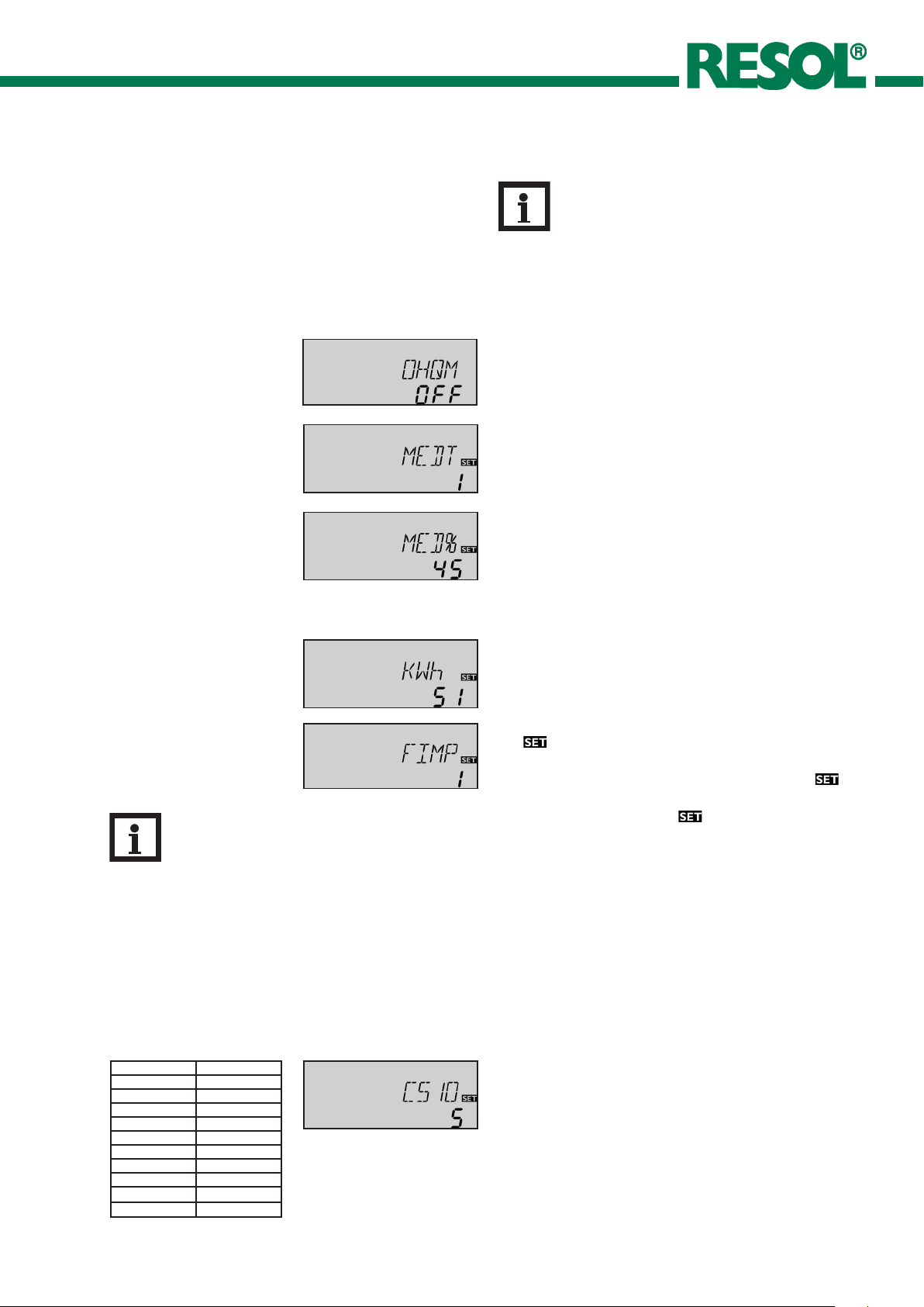
OHQM: Heat quantity measurement
adjustment range: “OFF”, “ON”
factory setting: “OFF”
MEDT: Type of antifreeze
adjustment range: “0” ... “3”
factory setting: “1”
MED%: Content of antifreeze in (Vol-) %
MED% is hidden at MEDT
“0” and “3”
adjustment range: 20 ... 70
factory setting: 45
kWh/MWh: Heat quantity
in kWh / MWh
display channel
FIMP: Volume per impulse
adjustment range: 1 ... 99
factory setting: 1
Note
You can find the l/imp of your flowmeter printed
on a flag that is attached to its cable.
Heat quantity measurement is possible if a flowmeter is
used. For this purpose, the heat quantity measurement
option (OHQM) has to be enabled.
The flow rate is measured at V40 (see display channel VSTR).
Antifreeze type and concentration of the heat transfer
medium have to be adjusted in the channels MEDT and
MED%.
Antifreeze type:
0 : water
1 : propylene glycol
2 : ethylene glycol
®
3 : Tyfocor
LS / G-LS
The flow rate as well as the reference sensors S7 (flow) S8
(return) are used for calculating the heat quantity supplied.
It is shown in kWh in the channel kWh and in MWh in the
channel MWh. The overall heat quantity results from the
sum of both values.
The accumulated heat quantity can be reset. As soon as
one of the display channels of the heat quantity is selected,
the symbol is permanently shown on the display. Press
button SET (3) for about 2 seconds in order to access the
RESET mode of the counter. The display symbol will
flash and the heat quantity value will be set to 0. In order to
finish this process, press the button to confirm.
In order to interrupt the RESET process, no button should
be pressed for about 5 seconds. The controller automatically
returns to the display mode.
IRR: Solar irradiation
intensity in W/m²
Display channel
CS10: Solar cell
adjustment range: 1 ... 10
factory setting: 5
Type Indicator
A 1
B 2
C 3
D 4
E 5
F 6
G 7
H 8
I 9
K 10
© RESOL DeltaSol ES_09190.monen.indd
The current solar irradiation intensity is measured in
W/m² by the sensor CS10.
The sensor is available in different types (see imprint on
packaging) and must be adjusted in channel CS10 with the
corresponding code number (see commissioning). The current irradiation is now shown in channel SOL.
19 |

D e lt a S o l® ES
4.3.2 ∆T-regulation
DT O / DT1O / DT2O / DT3O:
switch-on temp. diff.
adjustment range: 1.0 ... 20.0 K
factory setting: 6.0
DT F / DT1F / DT2F / DT3F:
switch-off temp.- diff.
adjustmentrange: 0.5 ... 19.5 K
factory setting: 4.0 K
DT S / DT1S / DT2S / DT3S:
nominal temp. diff.
adjustment range: 1.5 ... 30.0 K
factory setting: 10.0
RIS / RIS1 / RIS2 / RIS3:
rise
adjustment range: 1 ... 20 K
factory setting: 2 K
4.3.3 Maximum store temperature
First the controller works as a standard differential
controller. If the switch-on difference (DT O / DT1O /
DT2O) is reached, the pump is activated at full speed for
10 seconds. The speed is then reduced to the minimum
pump speed value (nMN / nMN1 / nMN2 = 30 %). If the
temperature difference reaches the adjusted set value (DT
S / DT1S / DT2S / DT3S), the pump speed increases
by one step (10%). If the difference increases by 2 K (RIS
/ RIS1 / RIS2 / RIS3), the pump speed increases by 10 %
respectively until the maximum pump speed of 100 % is
reached. The response of the controller can be adapted
via the parameter „Rise“. If the temperature difference
falls below the adjusted switch-off temperature difference
(DT F / DT1F / DT2F), the controller switches off.
DT O and DT S are locked against each other. DT S
must be at least 0,5 K higher than DT O.
Note
The switch-on temperature difference must
be at least 1 K higher than the switch-off
temperature difference.
S MX / S1MX / S2MX:
maximum store temp.
adjustment range: 2 ... 95 °C
factory setting: 60 °C
4.3.4 ∆T-regulation (solid fuel boiler and heat exchange)
Maximum temperature limitation
MX3O / MX3F:
maximum temperature
limitation
adjustment range:
0.0 ... 95.0 °C
factory setting:
MX3O 60.0 °C
MX3F 58.0 °C
Minimum temperature limitation
MN3O / MN3F:
minimum temperature
limitation
adjustment range:
0.0 ... 90.0 °C
factory setting:
Arr = 2
MN3O 5.0 °C
MN3F 10.0 °C
Arr = 8
MN3O 60.0 °C
MN3F 65.0 °C
| 20
Once the adjusted maximum temperature is exceeded,
the solar pump is switched off and further loading of the
store is prevented to reduce scald risk or system damage.
The
The controller is equipped with an independent temperature differential regulation for which minimum and
maximum temperature limitations as well as corresponding switch-on and -off temperatures can be separately
adjusted. Only possible for Arr = 2, 8, 11, 13, 16, 17, 18, 20,
24, 26 and 30 (e.g. for solid fuel boilers or heat exchange
regulation.)
If MX3O is exceeded, relay 2 is switched off until the
sensor falls below MX3F.
Reference sensor for this function:
S3 at Arr 8, 13, 20, 26 (TSTU)
S4 at Arr 2, 11, 16, 17, 18, 24, 30 (TST2, TFSB)
If the sensor temperature falls below MN3O, relay 3
is switched off until the temperature exceeds MN3F..
Reference sensor for this function:
S4 at Arr 8, 13, 20, 26 (TST2, TFSB)
S3 at Arr 2, 11, 16, 17, 18, 24, 30 (TSTU)
Both switch-on and switch-off temperature differences
DT3O and DT3F are valid for the maximum and minimum temperature limitation.
symbol is shown on the display.
Note
The controller is also equipped with a nonadjustable emergency switch-off if the store
reaches 95 °C. The reference sensor is S2 (or
S3 for two store systems).
© RESOL DeltaSol ES_09190.monen.indd

D e lt a S o l® ES
4.3.5 Collector limit temperature
collector emergency shutdown
EM EM1 / EM2:
collector limit
temperature
adjustment range:
110 ... 200 °C
factory setting: 140 °C
4.3.6 System cooling
OCX / OCX1 / OCX2:
option system cooling
adjustment range: “OFF”, “ON”
factory setting: “OFF”
CMX / CMX1 / CMX2:
collector maximum
temperature
adjustment range:
100... 190 °C
factory setting: 120 °C
If the adjusted collector limit temperature (EM / EM1 /
EM2) is exceeded the solar pump (R1 / R2) is deactivated
in order to avoid a damaging overheating of the solar components (collector emergency shutdown). The limit temperature is set to 140 °C by but it can be changed within the
adjustment range of 110 ... 200 °C. The symbol
on the display (flashing).
When the adjusted maximum store temperature is reached,
the system stagnates. If the collector temperature increases
to the adjusted maximum collector temperature (CMX
/ CMX1 / CMX2), the solar pump is activated until the
collector temperature falls below the maximum collector
temperature. The store temperature may increase (subordinate active maximum store temperature), but only up
to 95 °C (emergency shutdown of the store). If the store
temperature is higher than the maximum store temperature
(S MX / S1MX / S2MX) and if the collector temperature
is at least 5 K below the store temperature, the solar system
remains activated until the store is cooled down below the
adjusted maximum temperature (S MX / S1MX / S2MX)
via the collector and the pipework.
If the system cooling function is enabled,
shown on the display. Due to the cooling function, the system will have a longer operation time on hot summer days
and guarantees thermal relief of the collector field and the
heat transfer fluid.
is shown
(flashing) is
4.3.7 Option minimum collector limitation
OCN / OCN1 / OCN2:
minimum collector limitation
adjustment range: “OFF”, “ON”
factory setting: “OFF”
CMN / CMN1 / CMN2:
minimum collector
temperature
adjustment range: 10 ... 90 °C
factory setting: 10 °C
4.3.8 Option antifreeze function
OCF / OCF1 / OCF2:
antifreeze function
adjustment range: “OFF”, “ON”
factory setting: “OFF”
CFR / CFR1 / CFR2:
antifreeze temperature
adjustment range:
-10 ... +10 °C
factory setting: 4.0 °C
The minimum collector temperature is the minimum
temperature which must be exceeded for the solar pump
(R1 / R2) to switch on. The minimum temperature prevents
the pump from being switched on too often at low collector
temperatures. If the temperature falls below the minimum
temperature,
The antifreeze function activates the loading circuit between
collector and store if the adjusted antifreeze function is
under-run in order to protect the medium from freezing
or coagulating. If the adjusted frost protection temperature
is exceeded by 1 °C, the loading circuit will be deactivated.
(flashing) is shown on the display.
Note
Since this function uses the limited heat quantity
of the store, the antifreeze function should be
used in regions with few days of temperatures
around the freezing point.
© RESOL DeltaSol ES_09190.monen.indd
21 |

D e lt a S o l® ES
4.3.9 Store sequence control
Respective adjustment values:
Factory setting Adjustment range
Priority [PRIO] 1 (2 / Layer store) 0-2
oscillating break-time [tSP] 2 min. 1-30 min.
oscillating charge time [tRUN] 15 min. 1-30 min.
D e lt a S o l
®
ES priority logic:
Priority:
Loading break time / store sequence control /
collector rise temperature
The above-mentioned options and parameters are used in
multi-store systems only.
PRIO 0: in 2-store systems with pump logic (e.g. Arr 6 and
17) if possible, parallel loading is effected; in 2-store systems
with valve logic (e.g. Arr 5) loading is effected in numerical
order.
PRIO 1: priority loading of store 1
PRIO 2: priority loading of store 2
This function aims to extract the maximum solar gain in 2
store systems. If the first priority store cannot be loaded,
the second priority is checked. If useful heat can be added,
it will be loaded for the „oscillating loading time“ („t-run“
- factory default 15 min.) After this, the loading process
stops and the controller monitors the increase in collector
temperature during the break time „t-st“. If it increases by
2°C, the break time timer starts again to allow the collector
to gain more heat. If it does not, but useful heat can be
added to the second priority store, the second store will
be loaded again for the „t-run“ time as before.
As soon as the switch-on condition of the priority store is
fulfilled, it will be loaded. If the switch-on condition of the
priority store is not fulfilled, loading of the second store
will be continued. If the priority store reaches its maximum
temperature, oscillating loading will not be carried out.
4.3.10 Recooling function
OREC:
option recooling
adjustment range: “OFF”, “ON”
factory setting: “OFF”
4.3.11 Tube collector function
O TC:
tube collector function
adjustment range: “OFF”, “ON”
factory setting: “OFF”
| 22
If the adjusted maximum store temperature (SMAX, S1MX,
S2MX) is reached, the solar pump remains activated in
order to avoid an overheating of the collector. The store
temperature might continue to increase but only up to
95 °C (emergency shutdown of the store). In the evening
the solar system continues running until the store is cooled
down to the adjusted maximum store temperature via
collector and pipes.
This function helps overcome the non-ideal sensor position
with some tube collectors.
This function operates within a given time frame (06:00 22:00 o‘clock). It activates the collector circuit pump for 30
seconds every 30 minutes in order to compensate for the
delayed temperature measurement.
The collector circuit pump is operated at 100 % speed for
10 seconds, then at 30 % speed for another 20 seconds.
If the collector sensor is defective or the collector is blocked,
this function is suppressed or switched-off.
© RESOL DeltaSol ES_09190.monen.indd
D e lt a S o l® ES
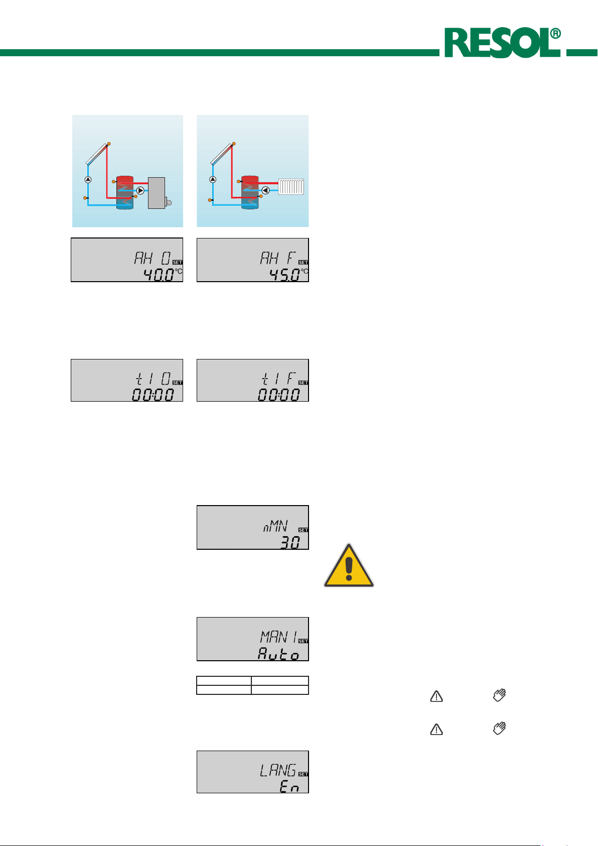
4.3.12 Thermostat function
after-heating Use of surplus energy
AH O:
thermostat-switch-on
temperature
adjustment range:
0.0 ... 95.0 °C
factory setting: 40.0 °C
t1 O, t2 O, t3 O:
thermostat switch-on time
adjustment range:
00:00 ... 23:45
factory setting: 00:00
AH F:
thermostat-switch-off
temperature
adjustment range:
0,0 ... 95.0 °C
factory setting: 45.0 °C
t1 F, t2 F, t3 F:
thermostat switch-off time
adjustment range:
00:00 ... 23:45
factory setting: 00:00
The thermostat function works independently from the
solar operation and can be used for using surplus energy
or for after-heating.
• AH O < AH F
thermostat function is used for after-heating
• AH F > AH O
thermostat function is used for using surplus energy
In order to block the thermostat function for a certain
period, there are three time frames t1 ... t3. If the function
should be active between 6:00 and 9:00, set t1 O to 6:00
and t1 F to 9:00. The thermostat function is factory set to
continuous operation.
If all time frames stop at 00:00 o’clock, the thermostat function is continuously activated (factory setting).
4.3.13 Pump speed control
nMN, n1MN, n2MN,
n3MN:
minimum pump speed
control
adjustment range: 30 ... 100
factory setting: 30
A relative minimum pump speed is specified for pumps
connected at the outputs R1 and R2 via adjustment channels
nMN, n1MN and n2MN.
ATTENTION:
When using loads (e.g. valves) which are
not pump speed controlled, the value must
be adjusted to 100 % in order to deactivate
4.3.14 Operating mode
MAN1, MAN2, MAN3,
MAN4, MAN5, MAN6:
operating mode
adjustment range:
“OFF”, “AUTO”, “ON”
factory setting: “AUTO”
Channel Relay
HNDx 1-6
For control- and service work the operating mode of
the controller can be manually adjusted by selecting
the adjustment value MAN1-6, in which the following
adjustments can be made:
• MAN1, MAN2, MAN3, MAN4, MAN5, MAN6
Operating mode
the pump speed control.
OFF : relay off (flashing) +
AUTO : relay in automatic operation
4.3.15 Language (LANG)
LANG:
adjustment of language
adjustment range:
“dE”, “En”, “It”, “Fr”
© RESOL DeltaSol ES_09190.monen.indd
factory setting: “dE”
ON : relay on
The menu language can be adjusted in this channel.
• dE : German
• En : English
• It : Italian
• Fr : French
(flashing) +
23 |

D e lt a S o l® ES
5. Troubleshooting
If a malfunction occurs, a notification is given on the display
of the controller :
warning symbol
can fuse T4A
spare fuse T4A
operating control lamp
Operating control lamp flashes red. The symbol and
the are shown.
Sensor fault. An error code instead of a temperature
is shown on the sensor display channel.
-88.8888.8
Cable is broken. Check
the cable.
Disconnected Pt1000 temperature sen sors
can be checked with an ohmmeter. In the
following table, the resistance values
corresponding to different temperatures
are listed.
Short-circuit. Check the
cable.
Operating control lamp off.
Check the power supply. Is it disconnected?
The fuse of the controller
could be blown. It can be
replaced after the front
cover has been removed
(spare fuse is enclosed in
the accessory bag).
Check the supply line and
reconnect it.
yesno
| 24
Resistance values of
the Pt1000-sensors
© RESOL DeltaSol ES_09190.monen.indd

D e lt a S o l® ES
5.1 Various:
Pump is overheated, but no heat transfer from the collector to the store, flow and return have the same temperature; perhaps also bubble in the lines
Air in the system?
Vent the system; in crease
system pre ssure to at
no yes
least static primary pressure plus 0,5 bar; if necessary increase the pressure,
switch the pump on and
off for a short time
Is the collector circuit
blocked at the dirt trap?
yes
Clean the dirt trap
Pump starts up very late..
Pu mp start s for a shor t moment , switches-o n/off
again,etc.
Is the temperature difference at the controller
too small?
no yes
Change ∆Ton and ∆Toff
correspondingly.
Wrong position of the
o.k.no
collector sensor?
no
yes
Mount the collector sensor at solar flow (warmest
collector output); use the
Plausibility control of the
tube collector function
immersion sleeve of the
respective collector.
The temperature difference between the store and the
collector increases enormously during operation; the
collector circuit cannot divert the heat.
Switch-on-temperature
difference ∆Ton too
large?
no yes
Non-ideal position of collector sensor (e.g. flatscrew
sensor instead of sensor in
immersion sleeves?)
yes
Change∆Ton and ∆Toff
correspondingly
Activate tube collector
function if necessary.
o.k.
Collector circuit pump
defective ?
no yes
Heat exchanger calcified?
no
yes
Heat exchanger blocked?
yesno
Heat exchanger too
small?
yes
Check / replace it
Decalify it
Clean it
Repalce with correctly
sized one
© RESOL DeltaSol ES_09190.monen.indd
25 |

D e lt a S o l® ES
Stores cool down at night.
Does the collector
circuit pump run in the
night?
no yes
At night, th e c ollector
tempe rature is hi gher
than the outdoor temperature.
no yes
Sufficient store insulation?
yes no
Check controller.
Check th e non-return
valve in flow and return
pipe with regard to the
functional efficiency.
Increase insulation.
a b
Check th e non-return
valve in warm water circulation- o.k.
yes no
The gravity circu lation in
the circulation line is too
strong; insert a stronger
valve in non-return valve
or an electric 2-port valve behind the circulation
pump; in pump operation,
the 2-port valve is open,
other wise it is closed, cone ct pump and 2-port
valve in parallel; activate
circulation again!
Further pumps which are
connected to the solar
store must also be checked.
Clean or replace
Insulation close enough
to the store?
yes no
Are the store connections insulated?
yes no
Warm water flow upwards?
no yes
Does warm water circulation run for a very long
time?
no yes
Circulatio n pump and
blocking valve should be
switched-off for 1 night;
less store losses?
yes no
Replace insulation or increase it.
Insulate the connections.
Change connection and
let the water flow sidewards or through a siphon
(bow downwards); less
store losses now?
no yes
o.k.
Use the circulation pump
with timer and switch-off
thermostat (energy efficient circulation)
Check whether the pumps
of the after-heating circuit runs at night, check
non-return valve; problem
solved?
The solar circuit pump does not run although the collector
is significantly warmer than the store.
Does the operating control lamp flash?
No current; check fuses
/ replace them and check
yes no
Does the pump start up
in manual operation?
no
yes
power supply.
The adjusted temperature
difference for starting the
pump is to high; choose a
value which makes more
sense.
Is the pump current released by the controller?
Is the pump stuck?
no
yes
yes
Turn the pump shaft using
a screwdriver; now passable?
no
Are the controller fuses
o.k.?
no yes
Pump is defective - replace it
| 26
no
a
b
Replace the fuses.
Controller might be defective - replace it.
© RESOL DeltaSol ES_09190.monen.indd

D e lt a S o l® ES
6. Accessories
Sensors
Our product range includes high-precision platin temperature sensors, flatscrew sensors, outdoor temperature
sensors, indoor temperature sensors, cylindrical clip-on
sensors and irradiation sensors, also as complete sensors
with immersion sleeve.
Overvoltage protection device
In order to avoid overvoltage damage at collector sensors
(e.g. caused by local lightning storms), we recommend installing the overvoltage protection RESOL SP1.
Flowmeter RESOL V40
The RESOL V40 is a measuring instrument for detecting
the flow of water or water/glycol mixtures and is used
in combination with the calorimeter integrated into the
D e lt a S o l
reed switch sends an impulse to the calorimeter. The heat
quantity used is calculated by the calorimeter using these
impulses and the measured temperature difference with the
help of pre-defined parameters (glycol type, concentration,
heat capacity, etc.).
®
M. After a specific volume has passed, the V40
RESOL ServiceCenter Software
The controller data can be read out for visualising and monitoring the system state. The software is availabe for free
download at www.resol.com
© RESOL DeltaSol ES_09190.monen.indd
27 |

D e lt a S o l® ES
Distributed by:
RESOL - Elektronische Regelungen GmbH
Heiskampstraße 10
45527 Hattingen / Germany
Tel.: +49 (0) 23 24 / 96 48 - 0
Fax: +49 (0) 23 24 / 96 48 - 755
www.resol.com
info@resol.com
Important notice:
We took a lot of care with the texts and drawings of this
manual and to the best of our knowledge and consent. As
faults can never be excluded, please note: Your own calculations and plans, under consideration of the current standards and DIN-directions should only be basis for your
projects. We don´t offer a guarantee for the completeness
of the drawings and texts of this manual - they only represent some examples. They can only be used at your own
risk. No liability is assumed for incorrect, incomplete or
false information and / or the resulting damages.
Please note:
The design and the specifications are to be changed without notice.
The illustrations may differ from the original product.
| 28
Reprinting / copying
This mounting- and operation manual including all parts is
copyrighted. Another use outside the copyright requires
the approval of RESOL - Elektronische Regelungen GmbH.
This especially applies for copies, translations, microfilms
and the storage into electronic systems.
Editor: RESOL - Elektronische Regelungen GmbH
© RESOL DeltaSol ES_09190.monen.indd
 Loading...