


DeltaSol
Solar controller for standard solar systems
with electric backup heating
Manual for the
specialised craftsman
Installation
Operation
Functions and options
Troubleshooting
®
AL E HE
beginning with version 2.01
*11210343*
11210343
The Internet portal for easy and secure access
to your system data – www.vbus.net
Thank you for buying this RESOL product.
Please read this manual carefully to get the best performance from this unit.
Please keep this manual safe.
en
Manual
www.resol.com

Safety advice
Please pay attention to the following safety advice in order to avoid danger and
damage to people and property.
Danger of electric shock:
• When carrying out works, the device must rst of all be disconnected from the
mains.
• It must be possible to disconnect the device from the mains at any time.
• Do not use the device if it is visibly damaged.
Instructions
Attention must be paid to the valid local standards, regulations and directives!
Information about the product
Proper usage
The solar controller is designed for use in standard solar thermal systems with
electric backup heating (electric immersion heater) in compliance with the techni-
en
cal data specied in this manual.
Improper use excludes all liability claims.
EU Declaration of conformity
The product complies with the relevant directives and is therefore labelled with the CE mark. The Declaration of Conformity is available
upon request, please contact the manufacturer.
Note
Strong electromagnetic elds can impair the function of the controller.
Î Make sure the controller as well as the system are not exposed to
strong electromagnetic elds.
Target group
These instructions are exclusively addressed to authorised skilled personnel.
Only qualied electricians are allowed to carry out electrical works.
Initial commissioning must be effected by authorised skilled personnel.
Description of symbols
WARNING!
Warnings are indicated with a warning triangle!
Î They contain information on how to avoid the danger
described.
Signal words describe the danger that may occur, when it is not avoided.
• WARNING means that injury, possibly life-threatening injury, can occur.
• ATTENTION means that damage to the appliance can occur.
Note
Notes are indicated with an information symbol.
Î Arrows indicate instruction steps that should be carried out.
Disposal
• Dispose of the packaging in an environmentally sound manner.
• At the end of its working life, the product must not be disposed of as urban
waste. Old appliances must be disposed of by an authorised body in an environmentally sound manner. Upon request we will take back your old appliances
bought from us and guarantee an environmentally sound disposal of the devices.
Subject to technical change. Errors excepted.
© 20191010_11210343_DeltaSol_AL_E_HE.monen.indd
2

Solar controller for standard solar systems with electric backup heating
®
The DeltaSol
AL E HE controller is especially designed for standard solar sys-
tems with a high-efciency pump and an electric backup heating.
It is equipped with a PWM output and two high-current relays to which an electric
immersion heater of up to 3 kW (230 V~) can be connected. The heater can be
directly connected to the controller without the need of auxiliary relays.
For data communication, the controller has a VBus
®
.
Contents
1 Overview ...............................................................................................4
2 Installation ............................................................................................5
2.1 Mounting .........................................................................................................................5
2.2 Electrical connection ....................................................................................................6
2.3 Grundfos Direct Sensor
TM
...........................................................................................7
2.4 PWM interface ...............................................................................................................7
2.5 Data communication / Bus ...........................................................................................7
2.6 Terminal allocation with cable link ............................................................................8
2.7 Terminal allocation without cable link ......................................................................9
3 Operation and function .....................................................................10
3.1 Buttons ......................................................................................................................... 10
3.2 System-Monitoring-Display ...................................................................................... 10
3.3 Slide switch .................................................................................................................. 12
3.4 Flashing codes .............................................................................................................12
3.5 Shortcuts for backup heating off, rapid heat-up and holiday mode ................ 12
4 Commissioning ...................................................................................13
5 Control parameters and display channels .......................................15
5.1 Channel overview ...................................................................................................... 15
6 Channel overview ...............................................................................17
6.1 Display channels .......................................................................................................... 17
6.2 Adjustment channels .................................................................................................20
7 RCTT Remote control (accessory) ..................................................33
8 Troubleshooting ..................................................................................34
9 Accessories .........................................................................................37
9.1 Sensors ......................................................................................................................... 38
9.2 VBus
®
accessories ...................................................................................................... 38
10 Index ....................................................................................................39
en
3

1 Overview
• Direct connection of an electric immersion heater up to 3 kW (230 V~)
• DHW heating with rapid heat-up and thermal disinfection
• Time and temperature control of the electric backup heating
• Solar backup heating suppression
• Heat quantity measurement via VFD Grundfos Direct Sensor
• PWM output for the speed control of a high-efciency pump
• Quick access to the holiday and the manual modes
• Status display for a bidirectional HE pump
• Drainback option and tube collector function
• Commissioning menu
Dimensions and minimum distances
en
180
180
208
Lower fastening
TM
Upper fastening
12.5
Technical data
Inputs: for 4 Pt1000 temperature sensors, thereof 1 x RCTT, 1 x Grundfos Direct
TM
Sensor
VFD, 1 x PWM feedback
Outputs: 1 semiconductor relay, 2 high-current relays for electric immersion
heater, 1 PWM output
PWM frequency: 512 Hz
PWM voltage: 10 V
Switching capacity:
1 (1) A 240 V~ (semiconductor relay)
14 (3) A 240 V~ / 24 V⎓ (potential-free high-current relay)
Power supply: 100 … 240 V~ (50 … 60 Hz)
Supply connection: type X attachment
Standby: 0.67 W
Temperature controls class: I
Energy efciency contribution: 1 %
Mode of operation: type 1.B.Y action
16.75
Rated impulse voltage: 2.5 kV
Data interface: VBus
VBus® current supply: 35 mA
100
144
Functions: function control, operating hours counter, tube collector function, heat
®
quantity measurement, time-controlled thermostat function, DHW heating with
rapid heat-up, thermal disinfection, holiday mode and backup heating suppression
Housing: plastic, PC-ABS and PMMA
Mounting: wall mounting, mounting into patch panels is possible
Indication / Display: System-Monitoring-Display for visualisation, 16-segment
display, 7-segment display, 8 symbols for system states, background illumination and
operating control LED
Operation: 3 push buttons and 1 slide switch
Ingress protection: IP 20 / EN 60529
43.3
Protection class: I
Ambient temperature: 0 … 40 °C [32 … 104 °F]
Pollution degree: 2
Dimensions: 144 x 208 x 43 mm
4

2 Installation
I
0 Auto I
I
2.1 Mounting
WARNING!
The unit must only be located in dry interior rooms.
If the device is not equipped with a mains connection cable and a plug, the device
must additionally be supplied from a double pole switch with contact gap of at
least 3 mm.
Please pay attention to separate routing of sensor cables and mains cables.
Î Unscrew the crosshead screw from the cover and remove the cover.
Î Mark the upper fastening point on the wall. Drill and fasten the enclosed wall
plug and screw leaving the head protruding.
Î Hang the housing from the upper fastening point and mark the lower fastening
points (centres 180 mm).
Î Drill and insert the lower wall plug.
Î Fasten the housing to the wall with the lower fastening screw and tighten.
Î Carry out the electrical wiring in accordance with the terminal allocation (see
page 6).
Î Put the cover on the housing.
Î Attach with the fastening screws.
Electric shock!
Upon opening the housing, live parts are exposed!
Î Always disconnect the device from power supply
before opening the housing!
Note
Strong electromagnetic elds can impair the function of the device.
Î Make sure the device as well as the system are not exposed to strong
electromagnetic elds.
1
0 Auto I
0 Auto I0 Auto I
3
2
4
0 Auto
en
180mm
5
0 Auto
6
0 Auto I
0 Auto I0 Auto I
Electrical connection see page 6
5

2.2 Electrical connection
WARNING!
Electric shock!
Upon opening the housing, live parts are exposed!
Î Always disconnect the device from power supply
before opening the housing!
ATTENTION!
ESD damage!
Electrostatic discharge can lead to damage to electronic components!
Î Take care to discharge properly before touching
the inside of the device! To do so, touch a grounded
surface such as a radiator or tap!
Note
Connecting the device to the power supply must always be the last step
of the installation!
en
Note
It must be possible to disconnect the device from the mains at any time.
Î Install the mains plug such that it is accessible at any time.
Î If this is not possible, install a switch that can be accessed.
If the mains cable is damaged, it must be replaced by a special connection
cable which is available from the manufacturer or its customer service.
Do not use the device if it is visibly damaged!
Attach exible cables to the housing with the enclosed strain relief and the corresponding screws.
The controller is supplied with power via a mains cable. The power supply of the
device must be 100 … 240 V~ (50 … 60 Hz).
The controller is equipped with 1 semiconductor relay to which a load such as
a pump, a valve, etc. can be connected:
17 Protective conductor ⏚
18 Neutral conductor N
19 Conductor R1
The controller is equipped with 2 high-current relays for connecting an electric
immersion heater of up to 3 kW:
16 Protective conductor ⏚
23 Mains conductor
22 Conductor electric immersion heater
21 Neutral conductor mains
20 Neutral conductor electric immersion heater
Depending on the product version, mains cables and sensor cables are already
connected to the device. If that is not the case, please proceed as follows:
Connect the temperature sensors (S1 to S5) to the corresponding terminals
with either polarity:
1/2 Sensor 1 (collector sensor)
3/4 Sensor 2 (store sensor base)
5/6 Sensor 3 (store sensor top)
7/8 Sensor 4 (return sensor)
DeltaSol® AL E HE
Made in Germany
VFD
terminal for a
S1
12
3456
sensor terminals
Grundfos Direct Sensor
6
S2
TM
IP 20
LED
S3
S4
9101112
78
RCTT terminals
PWM
PFB
PWM terminals
VBus
13 14
®
VBus
protective conductor
common terminal block
1 (1) A (100 ... 240) V~
R1
R2
14 (3) A (100 ... 240) V~
N
1615
17
R1
18
19
R2-N
20 21
R2-N
22 23
R2-L
load terminals
T2A
100 ... 240 V~
50-60 Hz
N
N
R2-L
24 25 26 27
mains terminals
LL

Connect the RCTT Remote control (accessory) to the following terminals:
M
7 GND RCTT Remote control
8 Switching input RCTT Remote control
9 Signal LED output RCTT Remote control
Connect the VBus® to the terminals marked VBus with either polarity:
13 VBus terminal
14 VBus terminal
The mains connection is at the following terminals:
25 Neutral conductor N
27 Conductor L
15 Protective conductor ⏚
The controller comes with the following cable links pre-connected:
24 Link from the neutral conductor to terminal 21
26 Link from the conductor L to terminal 23
2.3 Grundfos Direct Sensor
TM
The controller is equipped with 1 input for a digital VFD Grundfos Direct Sensor™
for measuring the ow rate and the temperature. Connection is made at the VFD
terminal (bottom left).
2.4 PWM interface
Speed control of a HE pump is possible via a PWM signal. The pump has to be
connected to the relay as well as to the PWM output of the controller. Power is
supplied to the HE pump by switching the corresponding relay on or off.
The terminal marked PFB is an interface for a bidirectional HE pump.
10 PWM output, control signal
11 PWM, GND
12 PWM input, feedback signal
brown
PW
101112
VBus
PFB
13 14
1615
N
17
blue
R1
18
19
brown
blue
green/yellow
black (optional)
230 V~ power
PWM signal cable
supply
pump power supplypump signal input
2.5 Data communication / Bus
The controller is equipped with the VBus
®
for data transfer and energy supply to
external modules. The connection is to be carried out at the terminals marked
VBus (any polarity). One or more VBus® modules can be connected via this data
bus, such as:
• SD3 smart Display / GA3 Large Display
• DL2 / DL3 Datalogger
• KM2 Communication module
Furthermore, the controller can be connected to a PC or integrated into a network via the VBus
®
/USB or VBus® /LAN interface adapter (not included). Different
solutions for visualisation and remote parameterisation are available on the website www.resol.com.
Note
More accessories on page 37.
en
7

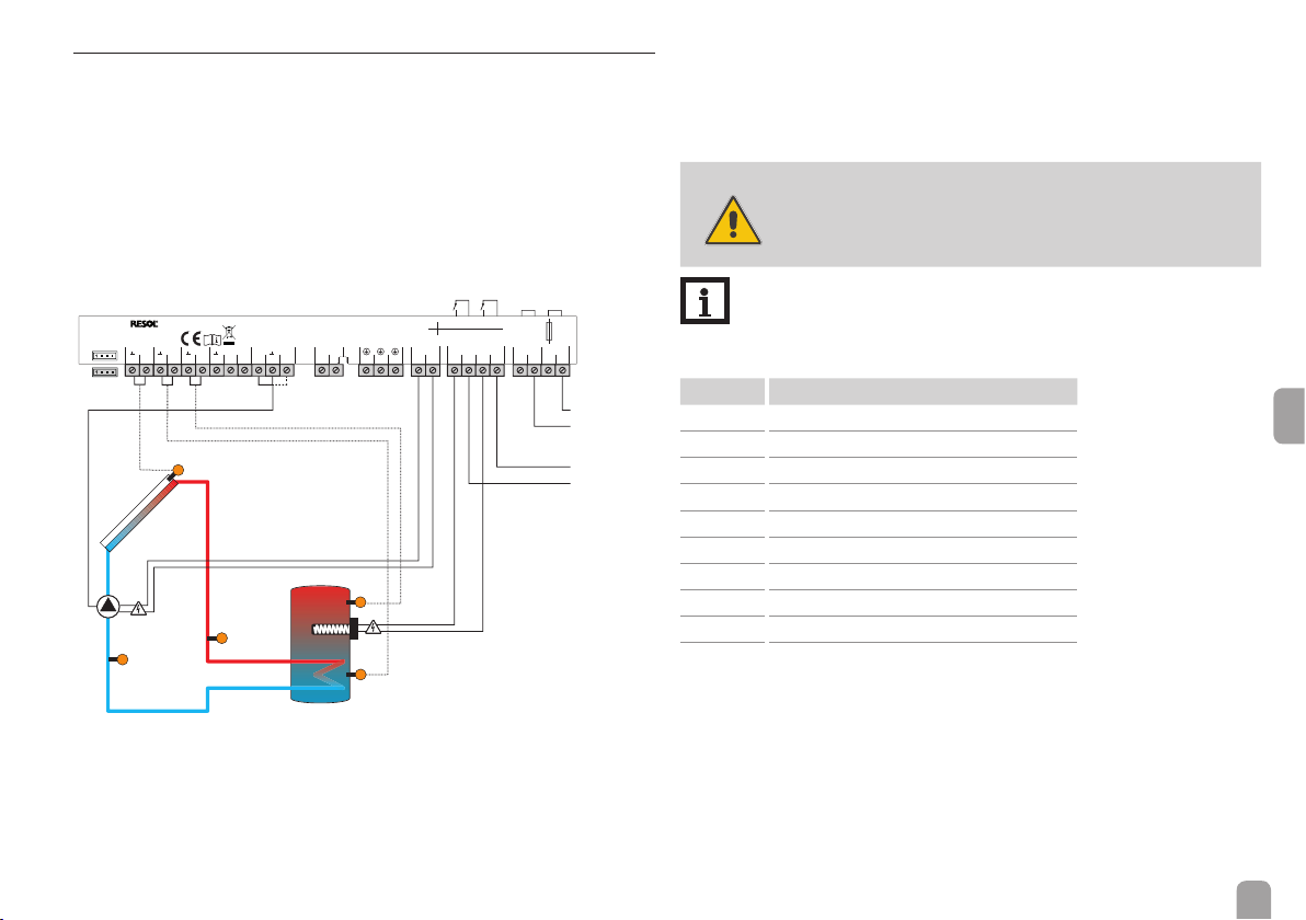
2.6 Terminal allocation with cable link
The controller calculates the temperature difference between collector sensor
S1 and store sensor S2. If the difference is larger than or identical to the adjusted
switch-on temperature difference (DT O), the solar pump will be activated by
relay 1, and the store will be loaded until the switch-off temperature difference
(DT F) or the maximum store temperature (S MX) is reached.
Sensor S3 is used for a thermostat function, which operates relay 2 for backup
heating purposes, when the adjusted thermostat switch-on temperature (BH O)
is reached. This function can optionally be combined with up to 3 adjustable time
frames.
1 (1) A (100 ... 240) V~
DeltaSol® AL E HE
Made in Germany
VFD
S1
S2
12
3456
IP 20
LED
S3
PWM
PFB
78
S4
9101112
VBus
13 14
R1
R2
14 (3) A (100 ... 240) V~
N
R1
1615
17
R2-N
20 21
18
19
T2A
100 ... 240 V~
50-60 Hz
N
LL
N
R2-L
R2-L
R2-N
22 23
24 25 26 27
en
S1
S3R1
S4 / VFD
VFD
S2
100 … 240 V~
Sensor S3 can optionally be used as the reference sensor for the thermal disinfection function (OTD) or the store emergency shutdown option (OSEM).
Sensor S4 can optionally be connected. For heat quantity measurement, S1 and S2,
S1 and VFD or VFD and S4 respectively can be used as ow and return sensors.
WARNING!
Electric shock!
Upon opening the housing, live parts are exposed!
Î Always disconnect the device from power supply
before opening the housing!
Note:
With this connection type, the immersion heater is supplied with power
directly from the mains connection.
Symbol Description
S1 Collector sensor
S2 Store sensor base
S3 Store sensor top
R1 Solar pump
R2-L Mains conductor
R2-L Conductor electric immersion heater
R2-N Neutral conductor mains
R2-N Neutral conductor electric immersion heater
⏚
L/N Mains terminals
Protective conductor
8
2.7 Terminal allocation without cable link
The controller calculates the temperature difference between collector sensor
S1 and store sensor S2. If the difference is larger than or identical to the adjusted
switch-on temperature difference (DT O), the solar pump will be activated by
relay 1, and the store will be loaded until the switch-off temperature difference
(DT F) or the maximum store temperature (S MX) is reached.
Sensor S3 is used for a thermostat function, which operates relay 2 for backup
heating purposes, when the adjusted thermostat switch-on temperature (BH O)
is reached. This function can optionally be combined with up to 3 adjustable time
frames.
1 (1) A (100 ... 240) V~
VFD
S4 / VFD
Made in Germany
S1
12
DeltaSol® AL E HE
S2
3456
S1
R1
R2
IP 20
LED
S3
PWM
PFB
78
S4
9101112
VBus
13 14
14 (3) A (100 ... 240) V~
N
R1
1615
17
R2-N
20 21
18
19
S3R1
VFD
S2
T2A
100 ... 240 V~
50-60 Hz
N
LL
N
R2-L
R2-L
R2-N
22 23
24 25 26 27
100 … 240 V~
100 … 240 V~
max. 3 kW
max. 14 A
Sensor S3 can optionally be used as the reference sensor for the thermal disinfection function (OTD) or the store emergency shutdown option (OSEM).
Sensor S4 can optionally be connected. For heat quantity measurement, S1 and S2,
S1 and VFD or VFD and S4 respectively can be used as ow and return sensors.
WARNING!
Electric shock!
Upon opening the housing, live parts are exposed!
Î Always disconnect the device from power supply
before opening the housing!
Note:
With this connection type, the immersion heater is supplied with power
indirectly via the mains connection.
Î Remove the pre-connected cable links.
Symbol Description
S1 Collector sensor
S2 Store sensor base
S3 Store sensor top
R1 Solar pump
R2-L Mains conductor
R2-L Conductor electric immersion heater
R2-N Neutral conductor mains
R2-N Neutral conductor electric immersion heater
⏚
L/N Mains terminals
Protective conductor
en
9

3 Operation and function
3.1 Buttons
The controller is operated via the 3 buttons next to the display:
Activating the rapid heat-up function (press and hold down button for 3 s)
Button
Button
Button :
During normal operation, display channels will be displayed.
Access to adjustment channels
en
If an adjustment channel is shown on the screen, Ⓢ will be displayed on the
right-hand side next to the channel name.
Ⓢ starts ashing.
Ⓢ permanently appears, the adjusted value has been saved.
:
Scrolling upwards, increasing adjustment values (press button briey)
:
⛁
Activating the holiday mode (press and hold down button for 3 s)
:
Ⓢ Conrming / selecting (press button briey)
:
Scrolling downwards, reducing adjustment values
Î In order to scroll between display channels, press buttons and .
Î Use button in order to scroll to the last display channel, then press and hold
down button for approx. 3 s.
Î Press button in order to select an adjustment channel.
Î Adjust the desired value with buttons and .
Î Briey press button .
3.2 System-Monitoring-Display
The System-Monitoring-Display consists of 3 blocks: channel display, tool bar
and system screen.
3.2.1 Channel display
The channel display consists of 2 lines. The upper display line is an alphanumeric
16-segment display. In this line, mainly channel names and menu items are displayed.
In the lower 7-segment display, values and parameters are displayed.
10

3.2.2 Tool bar
The additional symbols in the tool bar indicate the current system state.
Permanently
shown
⓵
⓶
☼
⓵ ☼
⓵ ☼
⓵ + ☼
⓵ + ☼
❄
⓵ ❄
☛ + ⓵
☛ + ⓶
☛ ⚠
☍ ⚠
Flashing Status indications:
Relay 1 active
Relay 2 active
Maximum store temperature exceeded
⚠ + ☼
⚠
⚠
❄
⚠
⚠
☍ + ⚠
3 x ☛
Store emergency shutdown active
Collector emergency shutdown active
Collector cooling active
System cooling active
Store cooling active
Holiday cooling active
Collector minimum limitation active
Antifreeze function activated
Antifreeze function active
Manual mode relay 1 ON
Manual mode relay 2 ON
Manual mode relay 1 / 2 OFF
Sensor fault
PWM feedback error message
Rapid heat-up not possible, because switch-off temperature exceeded
3.2.3 System screen
The system scheme is indicated on the System-Monitoring-Display. It consists of
several system component symbols which are – depending on the current status of
the system – either ashing or permanently shown.
Collector
Temperature sensor
with collector sensor
Pump
Store
with heat exchanger
Electric backup heating
(electric immersion heater)
en
11

3.3 Slide switch
By means of the slide switch, the controller can be set to different operating modes:
• Backup heating off = ☼ (left)
• Manual mode = ☛ (right)
• Automatic =
en
3.4 Flashing codes
3.4.1 System screen
• Pump symbols are ashing when the corresponding relay is on.
• Sensor symbols are ashing if the corresponding sensor display channel is
selected.
• Sensors symbols are ashing quickly in the case of a sensor fault.
3.4.2 Operating control LED
Green: everything OK
Green ashing: holiday mode / rapid heat-up active
Red/green ashing: initialisation / manual mode
Red ashing: sensor fault (sensor symbol is ashing quickly)
(centre)
Slide switch
3.5 Shortcuts for backup heating off, rapid heat-up and holiday mode
Slide switch position left ☼
Backup heating off
There will be no backup heating or thermal disinfection. The upper heat exchanger
in the System-Monitoring-Display will not be indicated, S3 will not be needed.
Slide switch position right ☛
Manual mode
Manual mode with a shortcut to the MAN1/2 parameters.
Button
Rapid heat-up
When button
adjusted in BOOS. The time will be indicated running backwards.
Button ⛁ (3 s)
Holiday mode
If button ⛁ is pressed and held down for approx. 3 s, the adjustment channel
DAY S appears, allowing to enter the number of days for an absence. If the parameter is set to a value higher than 0, the holiday mode becomes active using
the adjustments that have previously been made in the holiday cooling menu. The
days will be counted backwards at 00:00. If the value is set to 0, the holiday mode
is deactivated.
(3 s)
is pressed for 3s, rapid heat-up will become active for the time
12

4 Commissioning
Commissioning
scrolling upwards (+)
Ⓢ (selection / adjustment mode)
scrolling downwards (-)
Î Connect the device to the mains.
The controller runs an initialisation phase.
When the controller is commissioned or when it is reset, it will run a commission-
ing menu. The commissioning menu leads the user through the most important
adjustment channels needed for operating the system.
Operation
adjustment mode ashing
changing a value ashing
conrming a value not ashing
to the next
parameter
1. Language
Î Adjust the desired menu language.
LANG
Language selection
Selection: dE, En, Fr, ES, It
Factory setting: dE
2. Temperature unit
Î Adjust the desired unit.
UNIT
Temperature unit
Selection: °F, °C
Factory setting: °C
3. Time
Î Adjust the clock time.
First of all adjust the hours, then the minutes.
TIME
Real time clock
4. Maximum store temperature
Î Adjust the desired maximum store temperature.
S MX
Maximum store temperature
Adjustment range: 4 … 95 °C [40 … 200 °F]
Factory setting: 60 °C [140 °F]
Note:
The controller is also equipped with a non-adjustable emergency shutdown, deactivating
the system if the store reaches 95 °C [200 °F].
en
13

Commissioning
5. Pump control type
Î Adjust the pump control type.
PUM
Pump control type
Selection: OnOF, PULS, PSOL, PHEA
Factory setting: PSOL
The following types can be selected: Adjustment for
standard pump without speed control
• OnOF (pump on / pump off)
Adjustment for standard pump with speed control
• PULS (burst control via semiconductor relay)
Adjustment for high-efciency pump (HE pump)
• PSOL (PWM prole for a HE solar pump)
en
• PHEA (PWM prole for a HE heating pump)
6. Minimum speed
Î Adjust the minimum speed for the corresponding
pump.
nMN
Minimum speed
Adjustment range: (10) 30 … 100 %
Factory setting: 30 %
Note:
The pump speed must be set to 100 % when
auxiliary relays or valves are connected.
7. Maximum speed
Î Adjust the maximum speed for the corresponding
pump.
nMX
Maximum speed
Adjustment range: (10) 30 … 100 %
Factory setting: 100 %
Note:
The pump speed must be set to 100 % when
auxiliary relays or valves are connected.
8. PWM feedback signal
Î Adjust the PWM feedback signal type.
PFB
PWM feedback signal
Selection: OFF, A, b
Factory setting: OFF
(A = Wilo pump, b = Grundfos pump)
Conrmation
Completing the commissioning menu
After the last channel of the commissioning menu has
been adjusted and conrmed, the controller asks for
conrmation of the adjustments.
Î In order to conrm the adjustments made in the
commissioning menu, press button .
Now the controller is ready for operation.
Note:
The adjustments carried out during commissioning can be changed anytime in the corresponding adjustment channel. Additional
functions and options can also be activated or
deactivated (see page 20).
14

5 Control parameters and display channels
5.1 Channel overview
Display channels
Channel Description Connection terminal Page
INIT x* ODB initialisation active - 17
FLL x* ODB lling time active - 17
STAB x* ODB stabilisation in progress - 17
BOOS x* Rapid heat-up active - 17
DAY S x* Holiday mode active - 17
COL x Temperature collector S1 17
TST s Temperature store 1 base (backup heating off) S2 18
TSTB x Temperature store 1 base S2 18
TSTT x Temperature store 1 top S3 18
TDIS s* Thermal disinfection temperature
(thermal disinfection)
S3 s Temperature store 1 top (backup heating off) S3 18
S4 x Temperature sensor 4 S4 18
TFL x* Temperature ow sensor S1 / S4 / VFD 18
TR x* Temperature return sensor S4 / VFD 18
VFD x* Temperature Grundfos Direct Sensor™ VFD 18
L/h x* Flow rate Grundfos Direct Sensor™ /
PWM feedback signal
n % x Speed R1 R1 18
h P1 x Operating hours R1 R1 20
h P2 x Operating hours R2 R2 20
kWh x* Heat quantity in kWh - 19
MWh x* Heat quantity in MWh - 19
CDIS s* Countdown of monitoring period
(thermal disinfection)
SDIS s* Starting time display (thermal disinfection) - 19
DDIS s* Disinfection period display (thermal disinfection) - 19
TIME x Time - 19
S3 18
VFD / PWM 18
- 19
Adjustment channels
Channel Description Factory setting Page
DT O x Switch-on temperature difference R1 6.0 K [12.0 °Ra] 20
DT F x Switch-off temperature difference R1 4.0 K [8.0 °Ra] 20
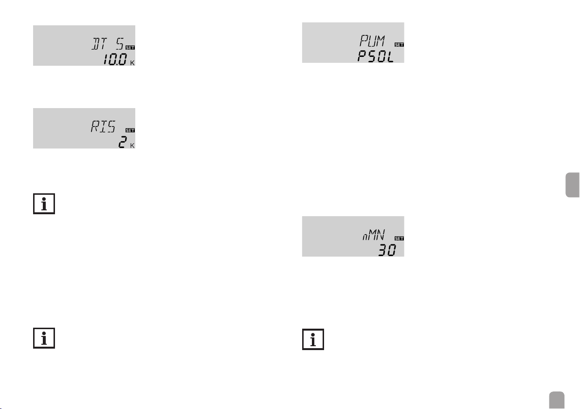
DT S x Set temperature difference R1 10.0 K [20.0 °Ra] 21
RIS x Rise R1 2 K [4 °Ra] 21
PUM x Pump control type R1 PSOL 21
nMN x Minimum speed R1 30 % 21
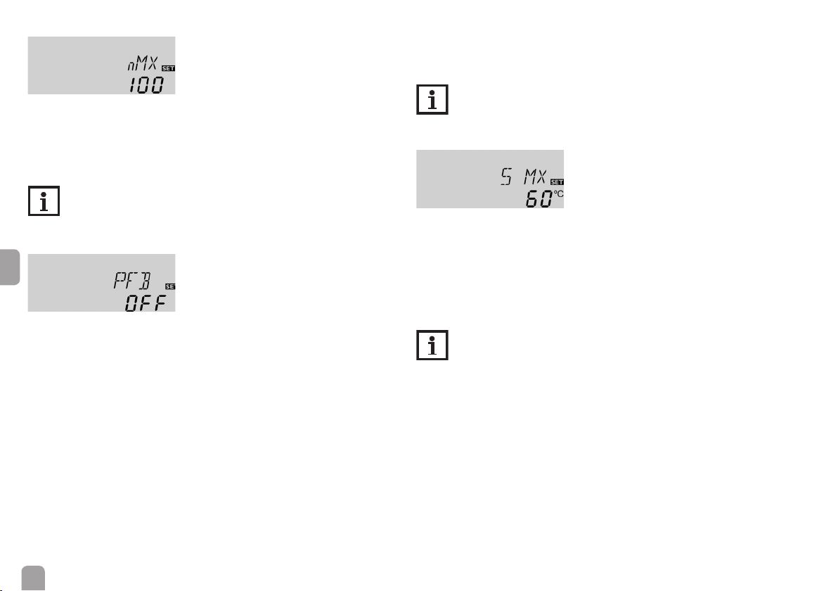
nMX x Maximum speed R1 100 % 22
PFB x* PWM feedback signal OFF 22
S MX x Maximum store temperature 60 °C [140 °F] 22
OSEM x Store emergency shutdown option OFF 23
EM x Collector emergency temperature 130 °C [270 °F] 23
OCC x Collector cooling option OFF 23
CMX x* Maximum collector temperature 110 °C [230 °F] 23
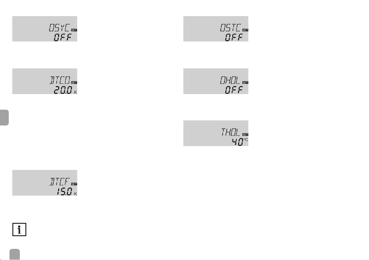
OSYC x System cooling option OFF 24
DTCO x* Switch-on temperature difference cooling 20.0 K [40.0 °Ra] 24
DTCF x* Switch-off temperature difference cooling 15.0 K [30.0 °Ra] 24
OSTC x Store cooling option OFF 24
OHOL x* Holiday cooling option OFF 24
THOL x* Holiday cooling temperature 40 °C [110 °F] 24
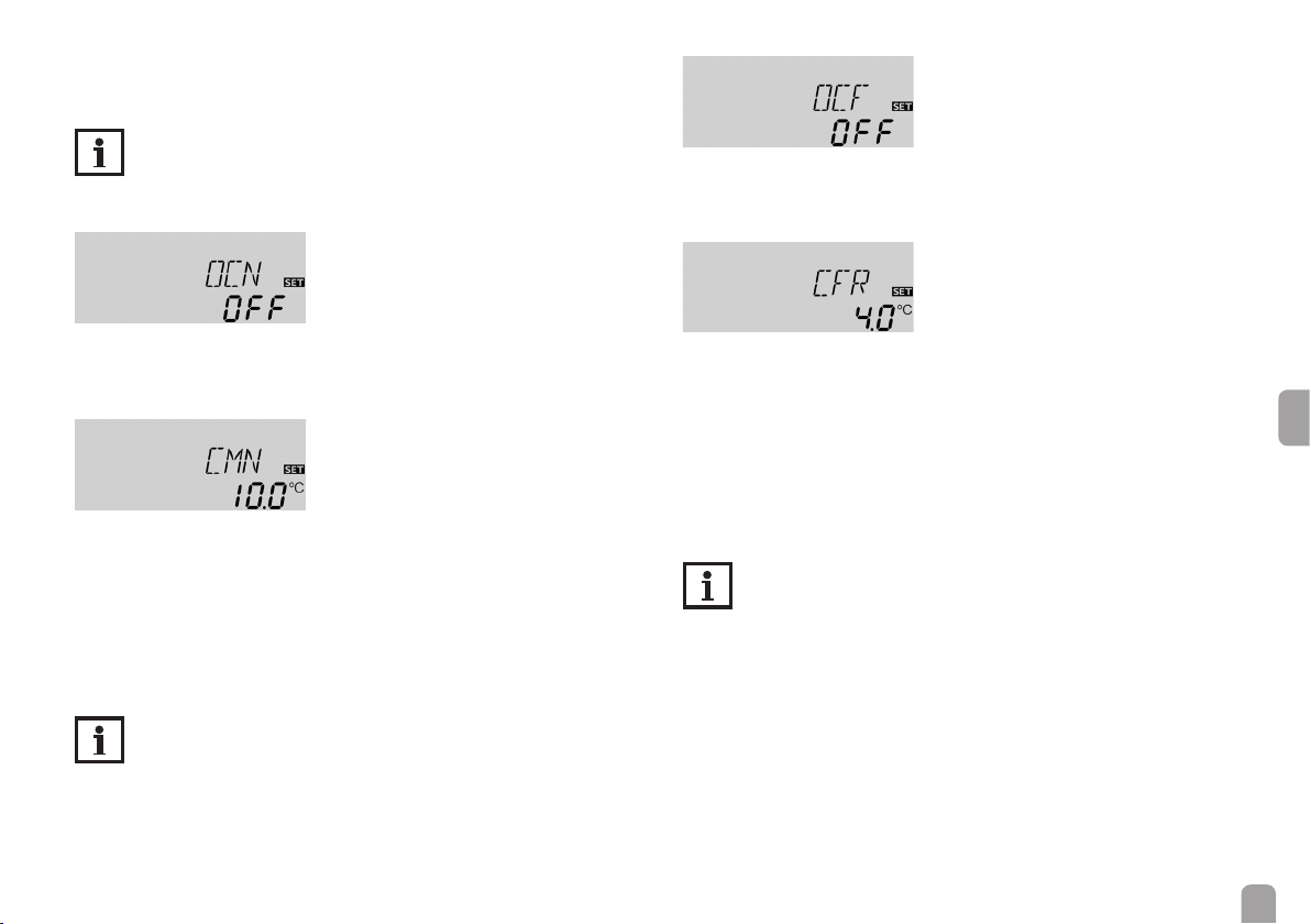
OCN x Collector minimum limitation option OFF 25
CMN x* Collector minimum temperature 10 °C [50 °F] 25
OCF x Antifreeze option OFF 25
CFR x* Antifreeze temperature 4.0 °C [40.0 °F] 25
OTC x Tube collector option OFF 26
TCST x* OTC starting time 07:00 26
TCEN x* OTC ending time 19:00 26
TCRU x* OTC runtime 30 s 26
TCIN x* OTC standstill interval 30 min 26
GFD x Grundfos Direct Sensor™ OFF 26
SEN x* VFD allocation 2 27
FMAX x* Maximum ow rate 6.0 l/min 27
MEDT x Antifreeze type 1 28
MED% x* Antifreeze concentration 40 % 28
en
15

Adjustment channels
Channel Description Factory setting Page
BHMN s Thermostat comfort temperature 40 °C [110 °F] 28
BH O s Switch-on temperature for thermostat 40 °C [110 °F] 28
BH F s Switch-off temperature for thermostat 45 °C [120 °F] 28
t1 O s Thermostat switch-on time 1 00:00 28
t1 F s Thermostat switch-off time 1 00:00 28
t2 O s Thermostat switch-on time 2 00:00 28
t2 F s Thermostat switch-off time 2 00:00 28
t3 O s Thermostat switch-on time 3 00:00 28
t3 F s Thermostat switch-off time 3 00:00 28
BOOS s Rapid heat-up runtime 90 min 29
ODB x Drainback option OFF 29
tDTO x* ODB switch-on condition - time period 60 s 30
tFLL x* ODB lling time 5.0 min 30
tSTB x* ODB stabilisation time 2.0 min 30
OTD s Thermal disinfection option OFF 30
en
PDIS s* Monitoring period 01:00 30
DDIS s* Disinfection period 01:00 30
TDIS s* Disinfection temperature 60 °C [140 °F] 30
SDIS s* Starting time 00:00 31
MAN1 x Manual mode R1 On 31
MAN2 x Manual mode R2 OFF 31
LANG x Language dE 32
UNIT x Temperature unit °C 32
RESE x Reset - back to factory settings 32
######## Version number
Symbol Description
x Channel is available
x* Channel is available, if the corresponding option is activated.
s System-specic channel
s* System-specic channel, only available if the corresponding option is activated
16

6 Channel overview
6.1 Display channels
Note:
The display and adjustment channels as well as the adjustment ranges depend on the system selected, the functions and options as well as on the
system components connected to the controller.
Display of drainback time periods
Initialisation
INIT
ODB initialisation active
Indicates the time adjusted in tDTO, running backwards.
Filling time
FLL
ODB lling time active
Indicates the time adjusted in tFLL, running backwards.
Stabilisation
STAB
ODB stabilisation in progress
Indicates the time adjusted in tSTB, running backwards.
Indication of rapid heat-up and days of absence
Rapid heat-up
BOOS
Rapid heat-up active
Indicates the time adjusted in BOOS, running backwards.
Days of absence
en
DAY S
Holiday mode active
Indicates the days adjusted, running backwards.
In this channel, the days of absence can also be adjusted.
Display of collector temperature
COL
Collector temperature
Display range: -40 … +260 °C [-40 … +500 °F]
Indicates the collector temperature.
17

Display of store temperatures
Display of further temperatures
TST, TSTB, TSTT, TDIS
Store temperatures
Display range: -40 … +260 °C [-40 … +500 °F]
Indicates the store temperatures.
• TST : Store temperature (backup heating off)
• TSTB : Store temperature base
• TSTT : Store temperature top
• TDIS : Thermal disinfection temperature
(replaces TSTT if, during thermal disinfection, the disinfection period DDIS is
active)
en
Display of sensors 3, 4 and VFD
S3, S4, VFD
Sensor temperatures
Display range: -40 … +260 °C [-40 … +500 °F]
VFD: 0 … 100 °C [32 … 212 °F]
Indicates the current temperature at the corresponding additional sensor (without
control function).
• S3 : Temperature at sensor 3 (backup heating off)
• S4 : Temperature at sensor 4
• VFD : Grundfos Direct Sensor™
Note:
S3 and S4 will only be indicated if the temperature sensors are connected
to the corresponding terminals. VFD will be indicated only if a Grundfos
Direct Sensor™ has been connected and registered.
TFL, TR
Further measured temperatures
Display range: -40 … +260 °C [-40 … +500 °F]
Indicates the current temperature at the corresponding sensor.
• TFL : Temperature ow
• TR : Temperature return
Indication of the ow rate
L/h
Flow rate / PWM feedback signal
Display range: depending on the sensor type used and the PWM feedback signal
selected respectively
Indicates the current ow rate at the VFD ow rate sensor or of the bidirectional
pump and its error messages respectively.
The display range depends on the sensor type selected.
Indication of current pump speed
n %
Current pump speed
Display range: 10 … 100 %
Indicates the current pump speed.
18

Display of heat quantity
kWh/MWh
Heat quantity in kWh / MWh
Display channel
Indicates the heat quantity produced in the system.
The heat quantity measurement can be carried out in 3 different ways (see page
27): with a xed ow rate value, with a VFD Grundfos Direct Sensor™ or with
a PWM feedback signal. It is shown in kWh in the channel kWh and in MWh in
the channel MWh. The overall heat quantity results from the sum of both values.
The accumulated heat quantity can be set back to zero. As soon as one of the display channels of the heat quantity is selected, the symbol Ⓢ is displayed.
Î In order to access the reset mode of the counter, press button for approx.
2 s.
Ⓢ starts ashing and the heat quantity value will be set back to zero.
Î In order to nish the reset, press button .
In order to interrupt the reset process, do not press any button for about 5 s. The
display returns to the display mode.
Indication of thermal disinfection
CDIS
Countdown of the
Monitoring period
Display range: 0 … 30:0 … 24 (dd:hh)
If the thermal disinfection option (OTD ) is activated and the monitoring period
is in progress, the remaining time is displayed as CDIS (in hours and minutes),
counting backwards.
SDIS
Display of starting time
Display range: 00:00 … 24:00 (hh:mm)
If the thermal disinfection option (OTD ) is activated and a starting delay time has
been adjusted, the adjusted starting time is displayed as SDIS (ashing).
DDIS
Display of disinfection period
Display range: 00:00 … 24:00 (hh:mm)
If the thermal disinfection option (OTD) is activated and the disinfection period
is in progress, the remaining time is displayed as CDIS (in hours and minutes),
counting backwards.
Display of time
TIME
Indicates the current clock time.
Î In order to adjust the hours, press button for approx. 2 s.
Î Set the hours by pressing buttons and .
Î In order to adjust the minutes, press button .
Î Set the minutes by pressing buttons and .
Î In order to save the adjustments, press button .
en
19
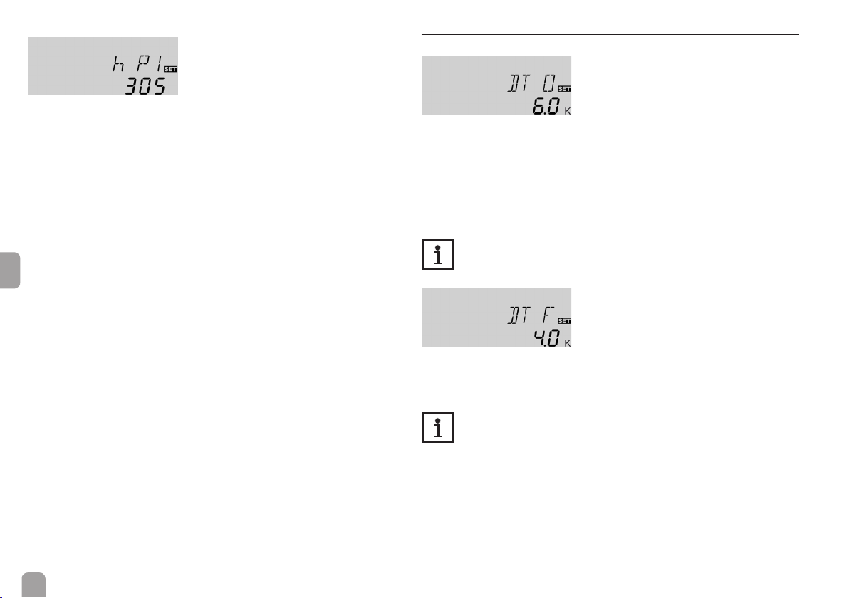
Operating hours counter
h P / h P1 / h P2
Operating hours counter
Display channel
The operating hours counter accumulates the operating hours of the correspond-
ing relays (h P / h P1 / h P2). Only full hours are displayed.
The accumulated operating hours can be set back to zero. As soon as an operating
hours channel is selected, the symbol Ⓢ is displayed.
Î In order to access the reset mode of the counter, press button for approx.
2 s.
Ⓢ starts ashing and the operating hours value will be set back to zero.
Î In order to nish the reset, press button .
en
In order to interrupt the reset process, do not press any button for about 5 s. The
display returns to the display mode.
6.2 Adjustment channels
∆T control
DT O
Switch-on temperature difference
Adjustment range: 1.0 … 20.0 K [2.0 … 40.0 °Ra]
Factory setting: 6.0 K [12.0 °Ra]
The controller works as a standard differential controller. If the temperature reaches or exceeds the switch-on temperature difference, the pump switches on.
When the temperature difference reaches or falls below the adjusted switch-off
temperature difference, the respective relay switches off.
Note:
The switch-on temperature difference must be at least 0.5 K [1 °Ra] higher than the switch-off temperature difference.
DT F
Switch-off temperature difference
Adjustment range: 0.5 … 19.5 K [1.0 … 39.0 °Ra]
Factory setting: 4.0 K [8.0 °Ra]
Note:
If the drainback option ODB is activated, the values of the parameters
DT O, DT F and DT S will be adapted to values suiting drainback sys-
tems:
DT O = 10 K [20 °Ra]
DT F = 4 K [8 °Ra]
DT S = 15 K [30 °Ra]
Adjustments that have been previously made in these channels will be
overridden and have to be entered again if ODB is deactivated later on.
20
Speed control
DT S
Set temperature difference
Adjustment range: 1.5 … 30.0 K [3.0 … 60.0 °Ra]
Factory setting: 10.0 K [20.0 °Ra]
RIS
Rise
Adjustment range: 1 … 20 K [2 … 40 °Ra]
Factory setting: 2 K [4 °Ra]
Note:
For pump speed control, the operating mode of the corresponding relay
must be set to Auto (adjustment channel MAN1 or slide switch position
centre respectively).
If the temperature difference reaches or exceeds the switch-on temperature difference, the pump switches on at 100 % speed for 10 s. Then, the speed is reduced
to the minimum pump speed value.
If the temperature difference reaches the adjusted set value, the pump speed increases by one step (10 %). The response of the controller can be adapted via the
parameter Rise. Each time the difference increases by the adjustable rise value, the
pump speed increases by 10 % until the maximum pump speed of 100% is reached.
If the temperature difference decreases by the adjustable rise value, pump speed
will be decreased by one step.
Note:
The set temperature difference must be at least 0.5 K [1 °Ra] higher than
the switch-on temperature difference.
PUM
Pump control type
Selection: OnOF, PULS, PSOL, PHEA
Factory setting: PSOL
With this parameter, the pump control type can be adjusted. The following types
can be selected:
Adjustment for standard pump without speed control
• OnOF (pump on / pump off)
Adjustment for standard pump with speed control
• PULS (burst control via semiconductor relay)
Adjustment for high-efciency pump (HE pump)
• PSOL (PWM prole for a HE solar pump)
• PHEA (PWM prole for a HE heating pump)
Minimum speed
nMN
Minimum speed
Adjustment range: (10) 30 … 100 %
Factory setting: 30 %
nMN, if ODB is activated: 50 %
In the adjustment channel nMN a relative minimum speed for a pump connected
can be allocated to the output R1.
Note:
The pump speed must be set to 100 % when auxiliary relays or valves are
connected.
en
21
Maximum speed
nMX
Maximum speed
Adjustment range: (10) 30 … 100 %
Factory setting: 100 %
In the adjustment channel nMX a relative maximum speed for a pump connected
can be allocated to the output R1.
Note:
The pump speed must be set to 100 % when auxiliary relays or valves are
connected.
PWM feedback signal
en
PFB
PWM feedback signal
Adjustment range: OFF, A, b
Factory setting: OFF
(A = Wilo pump, b = Grundfos pump)
With this parameter, the type of the PWM feedback signal of a bidirectional HE
pump can be adjusted. The signal transmits either a ow rate between 0 … 2100 l/h
or an error message.
The following messages can be displayed:
Err1: PWM interface of the pump defective
Err2: The pump is not running optimally, external cause electronics (e. g. overvolt-
age, low voltage)
Err3: The pump stops, but is operable, external cause electronics (e. g. overvoltage,
low voltage)
Err4: The pump stops, but is operable, external cause installation / hydraulics
Err5: The pump stops, but is not operable, internal cause electronics / pump is
stuck
Err6: PWM feedback signal connection defective
Note
If there is an error, the ow rate will not be indicated and the heat quantity measurement will not be carried out.
Maximum store temperature
S MX
Maximum store temperature
Adjustment range: 4 … 95 °C [40 … 200 °F]
Factory setting: 60 °C [140 °F]
If the store temperature reaches the adjusted maximum temperature, the store
will no longer be loaded in order to avoid damage caused by overheating. A non-adjustable hysteresis of 2 K [4 °Ra] is set for the maximum store temperature.
If the maximum store temperature is exceeded, ☼ is displayed.
Note:
If the collector cooling or the system cooling function is activated, the
adjusted maximum store temperature may be exceeded. In order to prevent system damage, the controller is also equipped with an integrated
store emergency shutdown, deactivating the system if the store reaches
95 °C [200 °F].
22

Store emergency shutdown
OSEM
Store emergency shutdown option
Adjustment range: OFF / ON
Factory setting: OFF
This option is used for activating the internal store emergency shutdown for an
upper store sensor. If the temperature at the reference sensor exceeds 95 °C
[200 °F], the store will be blocked and loading will be stopped until the temperature falls below 90 °C [190 °F].
Note:
S3 is used as the reference sensor.
Collector limit temperature
Collector emergency shutdown
EM
Collector limit temperature
Adjustment range: 80 … 200 °C [170 … 390 °F]
Factory setting: 130 °C [270 °F]
When the collector temperature exceeds the adjusted collector limit temperature,
the solar pump (R1) switches off in order to protect the system components
against overheating (collector emergency shutdown). If the collector limit temperature is exceeded, ⚠ is displayed.
Note:
If the drainback option ODB is activated, the adjustment range of EM is
changed to 80 … 120 °C [170 … 250 °F]. The factory setting in that case
is 95 °C [200 °F].
Cooling functions
In the following the 3 cooling functions – collector cooling, system cooling and
store cooling – are described in detail. The following note is valid for all 3 cooling
functions:
Note:
The cooling functions will not become active as long as solar loading is
possible.
Collector cooling
OCC
Collector cooling option
Adjustment range: OFF / ON
Factory setting: OFF
en
CMX
Collector maximum temperature
Adjustment range: 70 … 160 °C [150 … 320 °F]
Factory setting: 110 °C [230 °F]
The collector cooling function keeps the collector temperature within the operating range by heating the store. If the store temperature reaches 95 °C [200 °F] the
function will switch off for safety reasons.
If the store temperature exceeds the adjusted maximum store temperature, the
solar system is switched off. If the collector temperature increases to the adjusted
maximum collector temperature, the solar pump is activated until the collector
temperature falls below the maximum collector temperature. The store temperature may then exceed the maximum store temperature, but only up to 95 °C
[200 °F] (emergency shutdown of the store).
If the collector cooling function is active, ⓵ and ☼ are displayed (ashing).
Note:
This function will only be available if the system cooling function (OSYC)
is deactivated.
23
System cooling
Store cooling
OSYC
System cooling option
Adjustment range: OFF / ON
Factory setting: OFF
DTCO
Switch-on temperature difference
Adjustment range: 1.0 … 30.0 K [2.0 … 60.0 °Ra]
en
Factory setting: 20.0 K [40.0 °Ra]
The system cooling function aims to keep the solar system operational for a longer
time. The function overrides the maximum store temperature to provide thermal
relief of the collector eld and the heat transfer uid on hot days. If the store temperature is higher than the adjusted maximum store temperature and the switchon temperature difference DTCO is reached, the solar pump remains switched
on or will be switched on. Solar loading is continued until either the temperature
difference falls below the adjusted value DTCF or the collector limit temperature
is reached. If the system cooling function is active, ⓵ and ☼ are displayed (ashing).
DTCF
Switch-off temperature difference
Adjustment range: 0.5 … 29.5 K [1.0 … 59.0 °Ra]
Factory setting: 15.0 K [30.0 °Ra]
Note:
This function will only be available, if the collector cooling function
(OCC) is deactivated.
24
OSTC
Store cooling option
Adjustment range: OFF / ON
Factory setting: OFF
OHOL
Holiday cooling option
Adjustment range: OFF / ON
Factory setting: OFF
THOL
Holiday cooling temperature
Adjustment range: 20 … 80 °C [70 … 175 °F]
Factory setting: 40 °C [110 °F]
When the store cooling function is activated, the controller aims to cool down the
store during the night in order to prepare it for solar loading on the following day.
If the adjusted maximum store temperature (S MX) is exceeded and the collector
temperature falls below the store temperature, the system will be reactivated in
order to cool down the store. Cooling will continue until the store temperature
has fallen below the adjusted maximum store temperature (S MX) again. A hysteresis of 2 K [4 °Ra] is set for the store cooling function.
Reference threshold temperature differences for the store cooling function are
DT O and DT F.
If no DHW consumption is expected for a longer period of time, the additional
holiday cooling option OHOL can be activated in order to extend the store cooling function. The adjustable temperature THOL then replaces the maximum store
temperature (S MX) as the switch-off temperature for the store cooling function.
When the holiday cooling function is activated, ☼ and ⚠ (ashing) are shown on
the display.
If the holiday cooling function is active, ⓵, ☼ and ⚠ are displayed (ashing).
Note:
The holiday cooling will only become active when the holiday mode is
triggered by means of button ⛁ (see page 12).
Minimum collector limitation
Antifreeze function
OCF
Antifreeze function option
Adjustment range: OFF / ON
Factory setting: OFF
OCN
Collector minimum limitation option
Adjustment range: OFF / ON
Factory setting: OFF
CMN
Minimum collector temperature
Adjustment range: 10.0 … 90.0 °C [50.0 … 190.0 °F]
Factory setting: 10.0 °C [50.0 °F]
If the collector minimum limitation option is activated, the pump (R1) is only
switched on if the adjustable collector minimum temperature is exceeded. The
minimum temperature prevents the pump from being switched on too often at low
collector temperatures. A hysteresis of 5 K [10 °Ra] is set for this function. If the
collector minimum limitation is active, ❄ is displayed (ashing).
Note:
If OSTC or OCF is active, the collector minimum limitation will be overridden. In this case, the collector temperature may fall below CMN.
CFR
Antifreeze temperature
Adjustment range: -40.0 … +10.0 °C [-40.0 … +50.0 °F]
Factory setting: +4.0 °C [+40.0 °F]
The antifreeze function activates the loading circuit between the collector and the
store when the temperature falls below the adjusted antifreeze temperature. This
will protect the uid against freezing or coagulating. If the adjusted antifreeze temperature is exceeded by 1 K [2 °Ra], the loading circuit will be deactivated.
If the antifreeze function is activated, ❄ is displayed. If the antifreeze function is
active, ⓵ and ❄ are displayed (ashing).
Note:
Since this function uses the limited heat quantity of the store, the antifreeze function should be used in regions with few days of temperatures
around the freezing point.
The antifreeze function will be suppressed if the store temperature falls
below +5 °C [+40 °F] in order to protect the store from frost damage.
25
en

Tube collector function
OTC
Tube collector option
Adjustment range: OFF / ON
Factory setting: OFF
TCST
Tube collector function starting time
Adjustment range: 00:00 … 23:45
en
Factory setting: 07:00
This function is used for improving the switch-on behaviour in systems with
non-ideal sensor positions (e. g. with some tube collectors). This function operates
within an adjusted time frame. It activates the collector circuit pump for an adjustable runtime between adjustable standstill intervals in order to compensate for the
delayed temperature measurement.
If the runtime is set to more than 10 s, the pump will run at 100 % for the rst 10 s
of the runtime. For the remaining runtime, the pump will be run at the adjusted
minimum speed. If the collector sensor is defective or the collector is blocked, this
function is suppressed or switched off.
TCEN
Tube collector function ending time
Adjustment range: 00:00 … 23:45
Factory setting: 19:00
TCRU
Tube collector function runtime
Adjustment range: 5 … 500 s
Factory setting: 30 s
TCIN
Tube collector function standstill interval
Adjustment range: 1 … 60 min
Factory setting: 30 min
Note:
If the drainback option ODB is activated, TCRU will not be available. In
this case, the runtime will be determined by the parameters tFLL and
tSTB.
Grundfos Direct Sensor™ registration
GFD
Grundfos Direct Sensor™ registration
Selection: OFF, 12, 40, 40F
Factory setting: OFF
Registration of a digital ow rate sensor which can be used for heat quantity measurement.
OFF : no Grundfos Direct Sensor™
12 : VFD 1-12 (water / propylene glycol mixture)
40 : VFD 2-40
40F : VFD 2-40 Fast (water only)
26

Heat quantity measurement
The heat quantity measurement can be carried out in 3 different ways (see below):
with a xed ow rate value, with a VFD Grundfos Direct Sensor™ or with a PWM
feedback signal.
Heat quantity measurement with xed ow rate value
The heat quantity balancing (estimation) uses the difference between the collector
and the store base temperatures and the entered ow rate (at 100 % pump speed).
Î Read the ow rate (l/min) and adjust it in the FMAX channel.
Î Adjust the antifreeze type and concentration of the heat transfer uid in the
channels MEDT and MED%.
FMAX
Flow rate in l/min
Adjustment range: 0.5 … 100.0
Factory setting: 6.0
Note:
The FMAX channel will be available only if the SEN channel has been set
to OFF or if no VFD Grundfos Direct Sensor™ is activated.
Heat quantity measurement with a VFD Grundfos Direct Sensor™
In order to use a VFD Grundfos Direct Sensor™ for heat quantity measurement,
proceed as follows:
Î Register the VFD Grundfos Direct Sensor™ in the GFD channel.
Î Adjust the position of the VFD Grundfos Direct Sensor™ in the SEN channel.
Î Adjust the antifreeze type and concentration of the heat transfer uid in the
channels MEDT and MED%.
Heat quantity measurement with a PWM feedback signal
In order to use a VFD Grundfos Direct Sensor™ for heat quantity measurement,
proceed as follows:
Î Register the PWM feedback signal of a bidirectional HE pump on the PFB
channel.
Î Adjust the antifreeze type and concentration of the heat transfer uid in the
channels MEDT and MED%.
The VFD Grundfos Direct Sensor™ can optionally be used for measuring the temperature:
Î Register the VFD Grundfos Direct Sensor™ in the GFD channel.
Î Adjust the position of the VFD Grundfos Direct Sensor™ in the SEN channel.
Note
if a VFD Grundfos Direct Sensor™ is optionally activated, it will not be
used for measuring the ow rate but for measuring the ow and return
temperature respectively.
Note
If the PWM feedback signal sends an error message, heat quantity measurement will not be carried out.
SEN
Digital ow rate sensor (only if GDF = 12, 40 or 40 F)
Selection: OFF, 1, 2
Factory setting: 2
Flow rate detection type:
OFF : PWM feedback signal or xed ow rate value (owmeter)
1 : PWM feedback signal or Grundfos Direct Sensor™ in the ow pipe
2 : PWM feedback signal or Grundfos Direct Sensor™ in the return pipe
Sensor allocation for heat quantity measurement:
1 2 OFF
SFL SRET SFL SRET SFL SRET
GFD S4 S1 GFD S1 S2
en
27

MEDT
Heat transfer uid
Adjustment range: 0 … 3
Factory setting: 1
Heat transfer uid:
0 : Water
1 : Propylene glycol
2 : Ethylene glycol
3 : Tyfocor
®
LS / G-LS
en
MED%
Antifreeze concentration
in Vol-% (MED% is not indicated when MEDT 0 or 3 is used.)
Adjustment range: 20 … 70 %
Factory setting: 40 %
Thermostat function for backup heating
Note:
The thermostat function is only available when the slide switch is in the
centre position.
Note:
The thermostat switch-on temperature can only be lower than or equal
to the thermostat switch-off temperature.
The thermostat function can be used for backup heating. S3 is used as the reference sensor.
If the temperature falls below the thermostat switch-on temperature BH O, relay
R2 is energised for backup heating. If the thermostat switch-off temperature BH F
is exceeded, the relay switches off.
The thermostat function is deactivated, if the thermostat switch-on temperature
and the thermostat switch-off temperature are set to an identical value.
Note:
When the holiday mode is active, the thermostat function will be suppressed.
Backup heating suppression
BHMN
Comfort temperature
Adjustment range: 0.0 … 95.0 °C [30.0 … 200.0 °F]
Factory setting: 40.0 °C [110.0 °F]
When solar loading is in progress, backup heating will be suppressed until the
temperature at S3 falls below the comfort temperature BHMN.
When BHMN and BH O are set to identical values, the function will be deactivated.
BH O
Thermostat switch-on temperature
Adjustment range:
0 … 95 °C [30 … 200 °F]
Factory setting: 40 °C [110 °F]
28
BH F
Thermostat switch-off temperature
Adjustment range:
0 … 95 °C [30 … 200 °F]
Factory setting: 45 °C [120 °F]
t1 (2, 3) O
Thermostat switch-on time
Adjustment range: 00:00 … 23:45
Factory setting: 00:00
t1 (2, 3) F
Thermostat switch-off time
Adjustment range: 00:00 … 23:45
Factory setting: 00:00
In order to block the thermostat function for a certain period, there are 3 time
frames t1 … t3. The switch-on and switch-off times can be adjusted in steps of 15 min.

If the thermostat function is supposed to run from 06:00 a.m. to 09:00 a.m. only,
adjust t1 O to 06:00 a.m. and t1 F to 09:00 a.m.
If the switch-on and switch-off times of a time frame are set to an identical value,
the time frame will be inactive.
If all time frames are set to 00:00, the thermostat function is solely temperature
dependent (factory setting).
Rapid heat-up
BOOS
Rapid heat-up runtime
Adjustment range: 0 … 300 min
Factory setting: 90 min
Adjustment of the maximum runtime for the rapid heat-up to be active.
Rapid heat-up enables immediate heating of the store even outside the adjusted
time frames.
If rapid heat-up is activated, the controller will switch on the backup heating of the
store. Rapid heat-up of the store will stop if the switch-off temperature BH F is
reached at sensor S3.
Î In order to activate the rapid heat-up, scroll to the rst display channel, press
and hold down button
for 3 s. It is also possible to press the button of the
RCTT Remote control (accessory) instead.
3 s
Î In order to deactivate the rapid heat-up, press and hold down the upper con-
troller button again for 3 s. It is also possible to press the button of the RCTT
Remote control again instead.
Note:
If the temperature at sensor S3 exceeds the adjusted switch-off temperature BH F while rapid heat-up is being activated, rapid heat-up will be
blocked.
Drainback option
Note:
A drainback system requires additional components such as a holding
tank. The drainback option should only be activated if all components
required are properly installed.
In a drainback system, the heat transfer uid will ow into a holding tank if solar
loading does not take place. The drainback option initiates the lling process if
solar loading is about to start. If the drainback option is activated, the following
adjustment can be made.
ODB
Drainback option
Adjustment range: OFF / ON
Factory setting: OFF
Note:
If the drainback option is activated, the cooling functions and the antifreeze function will not be available. If one or more than one of these
functions have been activated before, they will be deactivated again as
soon as ODB is activated. They will remain deactivated, even if ODB is
deactivated later on.
Note:
If the drainback function ODB is activated, the factory settings of the parameters nMN, DT O, DT F and DT S will be adapted to values suiting
drainback systems.
Additionally, the adjustment range and the factory setting of the collector
emergency shutdown will change. Adjustments previously made in these
channels will be overridden and have to be entered again if the drainback
option is deactivated later on.
en
29

Time period – switch-on condition
Thermal disinfection of the upper DHW zone
tDTO
Time period – switch-on condition
Adjustment range: 1 … 100 s
Factory setting: 60 s
The parameter tDTO is used for adjusting the time period during which the
switch-on condition must be permanently fullled.
Filling time
en
tFLL
Filling time
Adjustment range: 1.0 … 30.0 min
Factory setting: 5.0 min
The lling time can be adjusted using the parameter tFLL. During this period, the
pump runs at 100 % speed.
Stabilisation
tSTB
Stabilisation
Adjustment range: 1.0 … 15.0 min
Factory setting: 2.0 min
The parameter tSTB is used for adjusting the time period during which the
switch-off condition will be ignored after the lling time has ended.
30
OTD
Therm. disinfection function
Adjustment range: OFF / ON
Factory setting: OFF
PDIS
Monitoring period
Adjustment range: 0 … 30:0 … 24 h (dd:hh)
Factory setting: 01:00
DDIS
Disinfection period
Adjustment range: 0:00 … 23:59 (hh:mm)
Factory setting: 01:00
TDIS
Disinfection temperature
Adjustment range: 0 … 95 °C [30 … 200 °F]
Factory setting: 60 °C [140 °F]
Reference sensor for this function is S3. R2 is the reference relay.
This function helps to contain the spread of Legionella in DHW stores by system-
atically activating the backup heating.

For thermal disinfection, the temperature at the reference sensor will be monitored. Protection is ensured when, during the monitoring period, the disinfection
temperature is continuously exceeded for the entire disinfection period.
The monitoring period starts as soon as the temperature at the reference sensor
falls below the disinfection temperature. When the monitoring period ends, the allocated reference relay activates the backup heating. The disinfection period starts,
if the temperature at the allocated sensor exceeds the disinfection temperature.
Thermal disinfection can only be completed when the disinfection temperature
is exceeded for the duration of the disinfection period without any interruption.
Starting time delay
SDIS
Starting time
Adjustment range: 0:00 … 24:00 (time)
Factory setting: 00:00
If the starting delay option is activated, a starting time for the thermal disinfection
with starting delay can be adjusted. The activation of the backup heating is then
delayed until that starting time after the monitoring period has ended.
If the monitoring period ends, for example, at 12:00 o'clock, and the starting time
has been set to 18:00, the reference relay will be energised with a delay of 6 hours
at 18:00 instead of 12:00 o'clock.
Note:
If the thermal disinfection option is activated, the display channels TDIS,
CDIS, SDIS and DDIS will be displayed.
Note:
The thermal disinfection function is only available when the slide switch is
in the centre position.
The function can also become active during holiday mode.
Operating mode
MAN1 / MAN2
Operating mode
Adjustment range: OFF, Auto, On
Factory setting: R1: On, R2: OFF
For control and service work, the operating mode of the relays can be manually
adjusted. For this purpose, select the adjustment value MAN1 (for R1) or MAN2
(for R2) in which the following adjustments can be made:
• MAN1 / MAN2
Operating mode
OFF : Relay off ⚠ (ashing) + ☛
Auto : Relay in automatic operation
ON : Relay on ⚠ (ashing) + ☛ + ⓵ / ⓶
If the slide switch is in the right-hand position, manual mode will become active
with the adjustments made previously. The parameters MAN1 / MAN2 can be
accessed directly via the shortcut (see page 12).
Note:
Always adjust the slide switch back to the center or left-hand position
when the control and service work is completed. Normal operation is not
possible in manual mode.
en
31

Language
Reset
LANG
Language selection
Selection: dE, En, Fr, ES, It
Factory setting: dE
In this adjustment channel the menu language can be selected.
• dE : German
• En : English
• Fr : French
• ES : Spanish
• It : Italian
Unit
en
UNIT
Temperature unit selection
Selection: °F, °C
Factory setting: °C
In this adjustment channel, the display unit for temperatures and temperature differences can be selected. The unit can be switched between °C / K and °F / °Ra
during operation.
Temperatures and temperature differences in °F and °Ra are displayed without
units. If the indication is set to °C, the units are displayed with the values.
RESE
Reset function
By means of the reset function, all adjustments can be set back to their factory
settings.
Î In order to carry out a reset, press button .
All adjustments that have previously been made will be lost! For this reason, a
security enquiry will appear after the reset function has been selected.
Only conrm the security enquiry if you are sure you want to set back all adjustment to the factory setting.
Security enquiry
Î In order to conrm the security enquiry, press button .
Note:
After a reset, the commissioning menu will start again (see page 13).
32

7 RCTT Remote control (accessory)
The RCTT Remote control enables rapid heat-up activation via the button without having to access the controller menu. It is connected to the controller with a
3-wire cable (see page 6).
If the button of the RCTT is pressed, rapid heat-up will be activated on the controller. If rapid heat-up is already active, it will be deactivated.
If rapid heat-up is active on the controller, the LED of the RCTT will be permanently red.
If rapid heat-up is not possible, because the temperature at sensor S3 has exceeded
the switch-off temperature BH F, the LED of the RCTT will briey ash 3 times.
In the case of a sensor fault, the LED of the RCTT will be ashing continuously.
The RCTT Remote control has to be connected to the controller according to the
installation instructions mentioned in the RCTT Remote control manual.
en
33
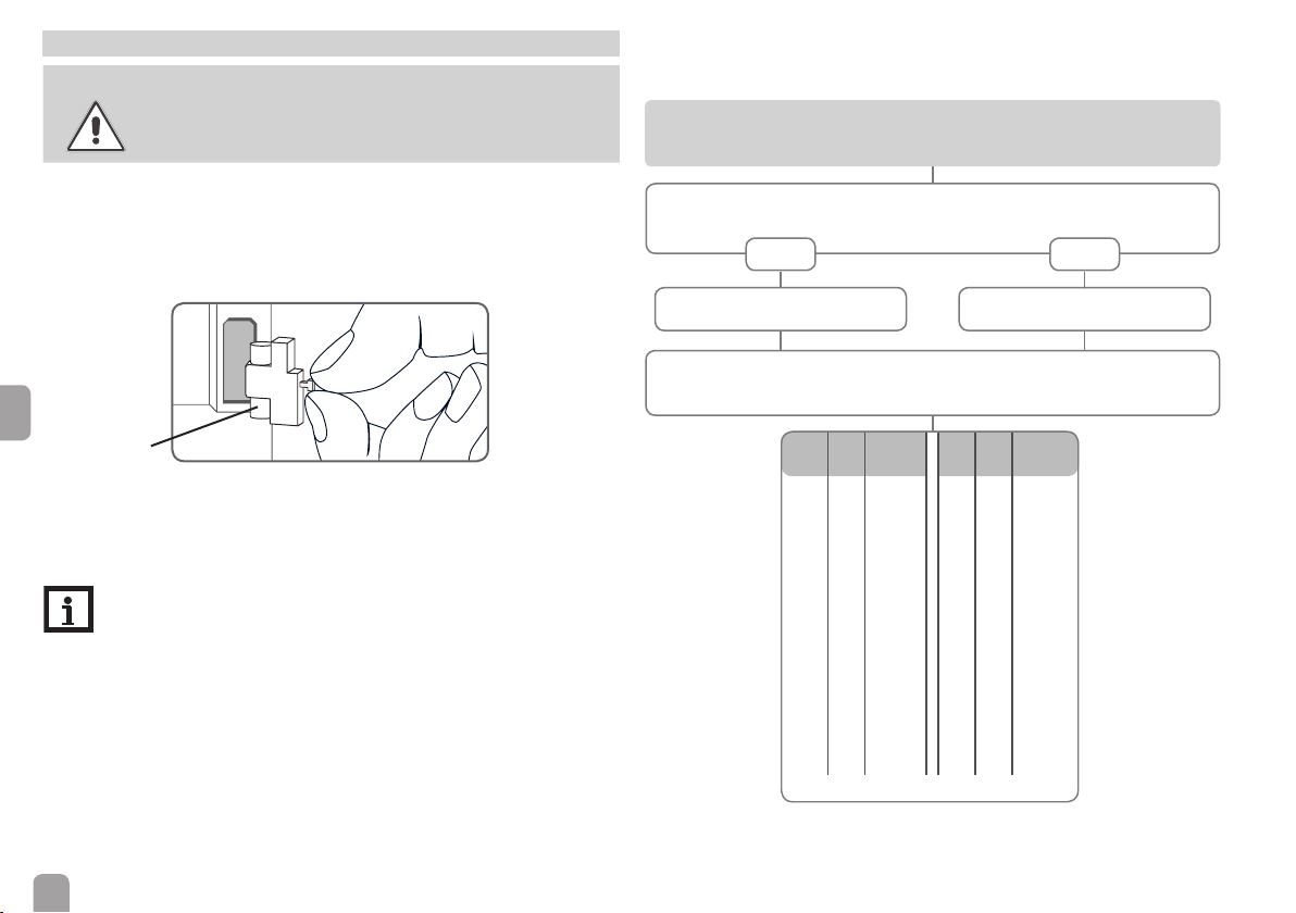
8 Troubleshooting
WARNING!
The controller is protected by a fuse. The fuse holder (which also holds the spare
fuse) becomes accessible when the cover is removed. To replace the fuse, pull the
fuse holder from the base.
en
Electric shock!
Upon opening the housing, live parts are exposed!
Î Always disconnect the device from power supply
before opening the housing!
If a malfunction occurs, the display symbols will indicate an error code (see page 11).
Operating control LED ashes red. The symbol ☍ is indicated on the display
and the symbol ⚠ is ashing.
Sensor fault. An error code instead of a temperature is shown on the sensor
display channel.
- 88.8888.8
Cable is broken. Check the cable. Short circuit. Check the cable.
Disconnected temperature sensors can be checked with an ohmmeter. Please
check if the resistance values correspond with the table.
Fuse
Note
For answers to frequently asked questions (FAQ) see www.resol.com.
34
°C °F Ω
Pt1000
-10 14 961 55 131 1213
-5 23 980 60 140 1232
0 32 1000 65 149 1252
5 41 1019 70 158 1271
10 50 1039 75 167 1290
15 59 1058 80 176 1309
20 68 1078 85 185 1328
25 77 1097 90 194 1347
30 86 1117 95 203 1366
35 95 1136 100 212 1385
40 104 1155 105 221 1404
45 113 1175 110 230 1423
50 122 1194 115 239 1442
°C °F Ω
Pt1000
Resistance values of Pt1000 sensors

Operating control LED is permanently off
Pump starts up very late.
If the operating control LED is off, check the power supply of the controller. Is
it disconnected?
no
The fuse of the controller could
be blown. The fuse holder (which
holds the spare fuse) becomes accessible when the cover is removed.
The fuse can then be replaced.
Pump is overheated, but no heat transfer from the collector to the store, ow
and return have the same temperature; perhaps also bubbling in the lines.
Air or gas bubbles in the system?
no
Is the collector circuit blocked at
the dirt trap?
Pump starts for a short moment, switches off, switches on again, etc.
Temperature difference at the
controller too small?
no
Wrong position of collector
sensors?
no
Plausibility control of the option
tube collector special function
yes
yes
yes
yes
Check the supply line and recon-
nect it.
Vent the system; increase the
system pressure to a static primary
pressure of at least plus 0.5 bar;
if necessary continue to increase
pressure; switch the pump on and
off for a short time.
Clean dirt trap
Change ∆Ton and ∆Toff corre-
spondingly.
no o.k.
Mount the collector sensor at
solar ow (warmest collector
output); use immersion sleeve of
the respective collector.
yes
Switch-on temperature difference
∆Ton too large?
no
Non-ideal position of the collector
sensor (e. g. atscrew sensor
instead of sensor in immersion
sleeves).
The temperature difference between store and collector increases enormously during operation; the collector circuit cannot dissipate the heat
Collector circuit pump defective?
no
Heat exchanger calcied?
no
Heat exchanger blocked?
no
Heat exchanger too small?
yes
yes
yes
yes
yes
yes
Change ∆Ton and ∆Toff corre-
spondingly.
Activate tube collector function if
necessary.
o.k.
Check / replace it
Decalcify it
Clean it
Replace with correctly sized one.
en
35

The solar circuit pump does not work, although the collector is considerably
warmer than the store
Is the operating control LED on?
yes
Does the pump start up in manual
operation?
no
Is the pump current enabled by
the controller?
no
Is the fuse of the controller OK?
en
no
Replace the fuse.
Controller might be defective replace it.
Store cools down at night.
Collector circuit pump runs
during the night?
no
Collector temperature at night is
higher than the outdoor temperature.
no
Sufcient store insulation?
yes
a
36
no
yes
yes
yes
yes
yes
no
There is no current; check fuses /
replace them and check power
supply.
The adjusted temperature difference for starting the pump is too
high; choose a value which makes
more sense.
Is the pump stuck?
Turn the pump shaft using a screw-
driver; now passable?
Pump is defective - replace it.
Check controller
Check the non-return valves in
the ow and the return pipe for
functional efciency.
Increase insulation.
yes
no
a
Insulation close enough to the
store?
yes
Are the store connections
insulated?
yes
Warm water outow upwards?
no
Does the DHW circulation run for
a very long time?
no
Circulation pump and blocking
valve should be switched off for 1
night; less store losses?
yes
Check the non-return valve in
warm water circulation - o.k.
yes
The gravitation circulation in the
circulation line is too strong; insert
a stronger valve in the non-return
valve or an electrical 2-port valve
behind the circulation pump; the
2-port valve is open when the pump
no
no
yes
yes
no
no
Replace insulation or increase it.
Insulate the connections.
Change connection and let the
water ow sidewards or through
a siphon (downwards); less store
losses now?
no
Use the circulation pump with
timer and switch-off thermostat
(energy-efcient circulation).
Check whether the pumps of the
backup heating circuit run at night;
check whether the non-return
valve is defective; problem solved?
Further pumps which are connected to the solar store must also be
checked.
Clean or replace it.
is activated, otherwise it is closed;
connect pump and 2-port valve
electrically in parallel; activate the
circulation again. Deactivate pump
speed control!
yes
o.k.
no
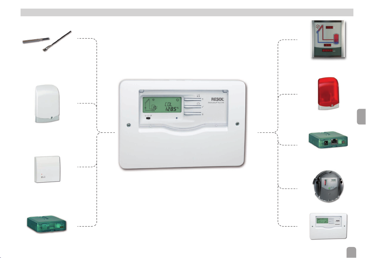
9 Accessories
Sensors
SD3 Smart Display /
GA3 Large Display
Overvoltage protection
device
RCTT Remote control
VBus® / USB & VBus® / LAN
interface adapters
AM1 Alarm module
KM2 Communication
module
DL2 Datalogger
DL3 Datalogger
en
37

9.1 Sensors
Sensors
The product range includes high-precision platinum temperature sensors, atscrew
sensors, outdoor temperature sensors, indoor temperature sensors, cylindrical
clip-on sensors, also as complete sensors with immersion sleeve.
Overvoltage protection device
Overvoltage protection device, suitable for mounting outdoors.
9.2 VBus
®
accessories
SD3 Smart Display / GA3 Large Display
The SD3 Smart Display is used for visualising data issued by the controller: collector temperature, store temperature and energy yield of the solar thermal system.
The GA3 is a completely mounted large display module for visualisation of collector- and store temperatures as well as the heat quantity yield of the solar system.
AM1 Alarm module
en
Alarm module for signalling system failures.
®
/ LAN interface adapter
VBus
The VBus® / LAN interface adapter is designed for the direct connection of the
controller to a PC or router. It enables easy access to the controller via the local
network of the owner.
DL2 Datalogger
For visualisation via VBus.net, incl. SD card and network cable, mains adapter and
®
cable pre-connected.
VBus
DL3 Datalogger
For visualisation via VBus.net, incl. SD card, mains adapter, network and VBus
KM2 Communication module
The KM2 Communication module is the ideal interface between a solar or heating
controller and the Internet. In only a few steps, the controller can be connected
to the VBus.net visualisation portal. The communication module is suitable for all
controllers with VBus
®
and enables the easy and secure access to system data via
VBus.net. Remote access to your controller is also possible, of course, via the RPT
Parameterisation Tool.
®
cable..
RCTT Remote control
The RCTT Remote control enables rapid heat-up activation via the button without
having to access the controller menu (see page 33).
VBus.net
The Internet portal for easy and secure access to your system data.
VBus.net is all about the data of your controller. Live data of your system, custom-
ized lter settings and much more await you.
38

10 Index
A
Accessories......................................................................................................................... 37
Antifreeze function ........................................................................................................... 25
B
Backup heating ................................................................................................................... 28
Backup heating suppression ............................................................................................ 28
C
Cable link .............................................................................................................................. 8
Collector cooling .............................................................................................................. 23
Collector emergency shutdown .................................................................................... 23
Commissioning .................................................................................................................. 13
Cooling function ................................................................................................................ 23
D
∆T control .......................................................................................................................... 20
Display ........................................................................................................................... 10, 17
Drainback option .............................................................................................................. 29
F
Flashing codes .................................................................................................................... 12
Flow rate ....................................................................................................................... 18, 27
G
Grundfos Direct Sensor™ ............................................................................................. 26
H
Heat quantity measurement ........................................................................................... 27
Holiday ........................................................................................................................... 12, 24
L
Language .............................................................................................................................. 32
M
Manual mode ................................................................................................................ 12, 31
Minimum collector temperature ................................................................................... 25
O
Operating hours counter ................................................................................................ 20
P
Pump control type ............................................................................................................ 21
PWM feedback .................................................................................................................. 22
PWM interface..................................................................................................................... 7
PWM signal ........................................................................................................................... 7
R
Rapid heat-up ..................................................................................................................... 12
Remote control ................................................................................................................. 33
Reset .................................................................................................................................... 32
S
Sensor .................................................................................................................................... 6
Shortcut .............................................................................................................................. 12
Slide switch ......................................................................................................................... 12
Speed control ..................................................................................................................... 21
Store cooling ...................................................................................................................... 24
System screen .................................................................................................................... 11
T
Temperature differential control (DT control) ........................................................... 20
Thermal disinfection ......................................................................................................... 30
Thermostat function ........................................................................................................ 28
Time ............................................................................................................................... 13, 19
Tool bar ............................................................................................................................... 11
Troubleshooting ................................................................................................................. 34
Tube collector function.................................................................................................... 26
V
®
..................................................................................................................................... 7
VBus
en
39

Distributed by:
RESOL – Elektronische Regelungen GmbH
Heiskampstraße 10
45527 Hattingen / Germany
Tel.: +49 (0) 23 24 / 96 48 - 0
Fax: +49 (0) 23 24 / 96 48 - 755
www.resol.com
info@resol.com
Important note
The texts and drawings in this manual are correct to the best of our knowledge. As
faults can never be excluded, please note:
Your own calculations and plans, under consideration of the current standards and
directions should only be basis for your projects. We do not offer a guarantee for
the completeness of the drawings and texts of this manual - they only represent
some examples. They can only be used at your own risk. No liability is assumed for
incorrect, incomplete or false information and / or the resulting damages.
Note
The design and the specications can be changed without notice.
The illustrations may differ from the original product.
Imprint
This mounting- and operation manual including all parts is copyrighted. Another
use outside the copyright requires the approval of RESOL – Elektronische Rege-
lungen GmbH. This especially applies for copies, translations, micro lms and the
storage into electronic systems.
© RESOL – Elektronische Regelungen GmbH
 Loading...