


DeltaSol
®
AL
Thank you for buying this RESOL product.
Please read this manual carefully to get the best performance from this unit.
Please keep this manual carefully.
RESOL DeltaSol® AL
Mounting
Connection
Operation
Troubleshooting
Examples
Manual
www.resol.com
*48006260*
48006260
en-US/CA

DeltaSol® AL
| 2
© RESOL 10341 deltasol_al.monus.indd
Description of symbols
Signal words describe the danger that may occur, when it
is not avoided.
• WARNING means that injury, possibly life-threaten-
ing injury, can occur.
• ATTENTION means that damage to the appliance
can occur.
Information about the product
Proper usage
The solar controller is designed for use in standard solar
thermal systems in compliance with the technical data specified in this manual.
Improper use excludes all liability claims.
Note
Notes are indicated with an information
symbol.
Disposal
• Dispose of the packaging in an environmentally sound
manner.
• Dispose of old appliances in an environmentally sound
manner. Upon request we will take back your old appliances bought from us and guarantee an environmentally
sound disposal of the devices.
Subject to technical change. Errors excepted.
Note
Strong electromagnetic fields can impair the
function of the controller.
Î Make sure the controller as well as the
system are not exposed to strong electromagnetic fields.
Î Arrows indicate instruction steps that should be carried out.
WARNING!
Warnings are indicated with a
warning triangle!
Î They contain information on how
to avoid the danger described.
Table of contents
Advice ........................................................................ 2
1. Overview .............................................................. 3
2. Installation ............................................................4
2.1 Mounting ........................................................................ 4
2.2 Electrical connection .................................................. 5
2.3 Data communication / Bus ........................................ 5
2.4 Terminal allocation ...................................................... 6
3. Operation .............................................................6
3.1 Buttons for adjustment .............................................. 6
3.2 System-Monitoring-Display ....................................... 7
3.3 Slide switch ................................................................... 8
3.4 Flashing codes ............................................................... 8
4. Control parameters and display channels ........9
4.1 Channel overview ........................................................ 9
4.2 Display and adjustment values .................................. 9
5. Troubleshooting ................................................. 14
5.1 Various ......................................................................... 15
6. Accessories .........................................................17
Copyright ................................................................. 20
Safety advice:
Please read the following information carefully before
installing and operating the controller. In this way damage
to the solar system caused by wrong installation will be
avoided. Please make sure that the mounting is adapted to
the characteristics of the building, that the local regulations
are respected and is conform with the technical rules.
Please pay attention to the following safety advice in order
to avoid danger and damage to people and property.
Instructions:
Attention should be paid to
• Valid national and local standards and regulations
• Respective valid standards and directives
Equipment to be installed and used in accordance with
the rules of the National Electrical Code (NEC) or with
Canadian Electrical Code (CEC), Part I.
These instructions are exclusively addressed to authorized
skilled personnel.
• Only qualified electricians should carry out installation
and maintenance work.
• Initial installation should be carried out by qualified personnel
General

DeltaSol® AL
3 |
© RESOL 10341 deltasol_al.monus.indd
• System-Monitoring-Display
• Easy-to-understandvisualiza-
tion of the system parameters
• Upto3Pt1000temperature
sensors
• Energymetering
• Functioncontrol
• Solaroperatinghourscounter
• Housingwithbrandnewdesign
• Intuitiveoperatingconcept
• RESOLVBus
®
• Energy-efcientthroughlow
standby power consumption
Technical data:
Housing:plastic, PC-ABS and PMMA
Protection type: IP 20 / EN 60529
Protection class: II
Ambient temp.: 0 ... 40 °C
[32 ... 104 °F]
Dimensions: 144 x 208 x 43 mm
Installation: wall mounting
Display: System-Monitor for visuali-
zation, 16-segment display, 7-segment
display, 8 symbols for system states,
background illumination and operating
control lamp
Operation: 3 push buttons at the
front of the housing and 1 slide switch
Functions: Differential temperature
controller for standard solar thermal
systems. Function control, operating
hours counter for the solar pump,
tube collector function and energy
metering.
Inputs: for 3 Pt1000 temperature
sensors
Outputs: 1 electromechanical relay
with change-over contact
Bus: RESOL VBus
®
Power supply: 100 ... 240 V~
(50 ... 60 Hz)
Power consumption:
standby: < 0.5 W
maximum: < 0.7 W
Total switching capacity:
4 (1) A (100 ... 240) V~
Mode of operation: Type 1.B
Switching capacity:
electromechanical relay:
4 (1) A (100 ... 240) V~
Included with the DeltaSol
®
AL
1 x DeltaSol
®
AL
1 x accessory bag
3 x screw and wall plug
5 x strain relief and screw
Additionally included in the full kit:
1 x FKP6 sensor
1 x FRP6 sensor
1. Overview
DeltaSol® AL
| 4
© RESOL 10341 deltasol_al.monus.indd
The unit must only be located in dry interior rooms. It is not
suitable for installation in hazardous locations and should be
protected against electromagnetic fields.
The controller must additionally be supplied from a double
pole switch with contact gap of at least 3 mm.
Please pay attention to separate routing of sensor cables
and power supply cables.
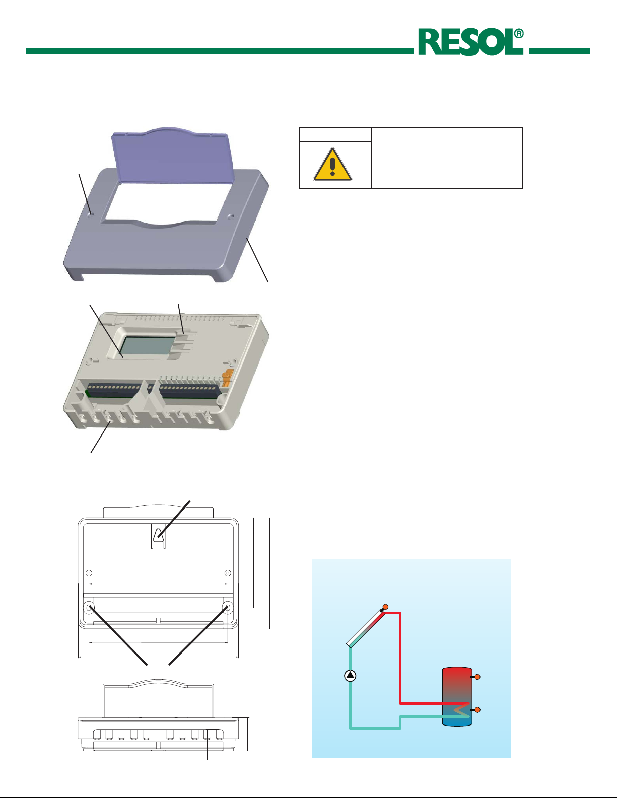
Î Unscrew the crosshead screw from the cover and
remove the cover
Î Mark the upper fastening point on the wall
Î Drill and fasten the enclosed wall plug and screw leaving
the head protruding
Î Hang the housing from the upper fastening point and
mark the lower fastening points (centres 180 mm)
Î Drill and insert the lower wall plug
Î Fasten the housing to the wall with the lower fastening
screw and tighten
2. Installation
System scheme DeltaSol® AL
Standard solar system
WARNING! Electric shock!
Î Always disconnect the con -
tro lle r from power sup ply
before opening the housing!
crosshead
screw
cover
cable conduits with
strain relief
push button
upper fastening
lower fastening
slide switch
2.1 Mounting
12.5
180
180
100
144
208
16.75
43.3

DeltaSol® AL
5 |
© RESOL 10341 deltasol_al.monus.indd
The controller is equipped with the RESOL VBus® for data
transfer with and energy supply to external modules. Carry
out the connection at the two terminals marked “VBus” (any
polarity). One or more RESOL VBus® modules can be connected via this data bus, such as:
• RESOL GA3 Large Display from version 1.21
• RESOL SD3 Smart Display from version 1.21
• RESOL DL2 Datalogger
• RESOL VBus
®
/ USB interface adapter
Connecting the device to the power supply must always be
the last step of the installation!
The controller is supplied with power via a power supply
line. The power supply of the device must be 100 ... 240 V~
(50 ... 60 Hz) .
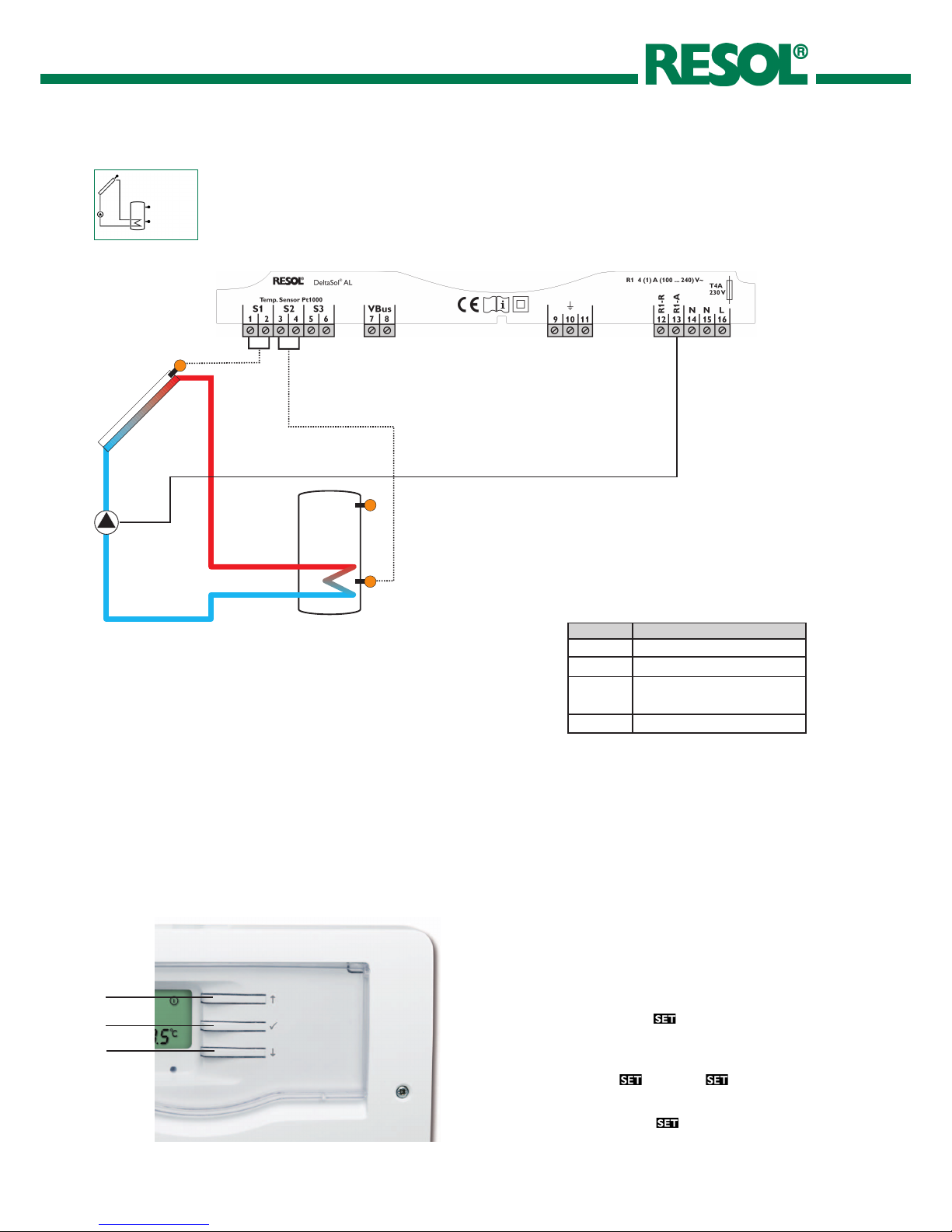
The controller is equipped with a change-over relay to which
a load such as a pump, a valve, etc. can be connected:
10 = ground terminal
11 = ground terminal
12 = conductor R1-R (normally closed contact)
13 = conductor R1-A (normally open contact)
14 = neutral conductor N
Depending on the product version, power supply cable and
sensor cables are already connected to the device. If that is
not the case, please proceed as follows:
Connect the temperature sensors (S1 to S3) to the
corres ponding terminals with either polarity:
1/2 = Sensor 1 (e. g. sensor collector)
3/4 = Sensor 2 (e. g. sensor tank)
5/6 = Sensor 3 (e. g. sensor tank top)
Connect the RESOLVBus
®
to the terminals marked
“VBus” with either polarity:
7 = VBus terminal
8 = VBus terminal
Connect the power supply cable to the following terminals:
15 = neutral conductor N
16 = conductor L
9 = ground terminal
Attach flexible cables to the housing with the enclosed
strain relief and the corresponding screws.
ATTENTION! ESD damage!
Electrostatic discharge can cause damage of electronic components!
Î Ta k e c a r e to d i s c h a r g e
proper ly before touching the
inside of the device!
2.2 Electrical connection
2.3 Datacommunication/Bus
DeltaSol® AL
| 6
© RESOL 10341 deltasol_al.monus.indd
2.4 Terminal allocation
Standard solar system with one tank, one pump and
three sensors. Sensors S1 / S2 are also used for energy
metering.
S1
S2
S3
R1
Symbol Description
S1 collector sensor
S2 tank sensor base
S3 tank sensor top
(optional)
R1-A solar pump
3. Operation
3.1 Buttonsforadjustment
The controller is operated via the three push buttons next
to the display. Button 1 is used for scrolling backwards
through the display menu or to increase the adjustment
values. Button 2 is similarly used for scrolling forward and
reducing values.
In order to access the adjustment mode, scroll down in the
display menu and press button 2 for approx. three seconds
after you have reached the last display item. If an adjustment
value is shown on the display, the
icon is displayed. Now,
you can access the adjustment mode by pushing button 3.
Î Select the requested channel using buttons 1 and 2.
Î Briefly press button 3,
will flash ( mode)
Î Adjust the value by pressing buttons 1 and 2
Î Briefly press button 3, so that
permanently appears;
the adjusted value will be saved.
3
1
2

DeltaSol® AL
7 |
© RESOL 10341 deltasol_al.monus.indd
The system monitoring display consists of three blocks:
channel display, tool bar and System-Screen.
The channel display consists of two lines. The upper line
is an alpha-numeric 16-segment display (text display) for
displaying channel names and menu items. In the lower
7-segment display, channel values and the adjustment parameters are displayed.
Temperatures and temperature differences in °C and K are
displayed with the unit. If the indication is set to °F and °Ra,
the units are not displayed.
3.2.1 Channel display
Channel display
3.2.2 Tool bar
The additional symbols in the tool bar indicate the current
system state.
Tool bar
3.2 System-Monitoring-Display
System-Monitoring-Display
Status normal blinkend
relay 1 active
maximum tank limitation active /
maximum tank
temperature exceeded
collector cooling function active
recooling function active
antifreeze function activated
collector minimum limitation active
antifreeze function active
collector emergency shutdown
active or tank emergency shutdown
active
sensor fault S1
sensor fault S2
manual mode active
an adjustment channel is being
changed - set mode

DeltaSol® AL
| 8
© RESOL 10341 deltasol_al.monus.indd
The system screen shows the system. The screen consists
of several system component symbols, which are – depending on the current status of the system – either flashing,
permanently shown or “hidden”.
Sensor
Collector
Pump
Tank
Tank heat exchanger
Sensor
Tank sensor top
Collector
with collector sensor
Pump
Tank
with heat exchanger
Temperature sensor
3.2.3 System-Screen
System-Screen
green: everything OK
red/green flashing: initialization phase
manual operation
red flashing: Sensor defective
(sensor symbol is flashing quickly)
3.4 Flashingcodes
3.4.2 LED flashing codes
3.4.1 System-Screenashingcodes
• Pumps are flashing during initialization phase
• Sensor symbols are flashing while the corresponding sen-
sor display channel is selected.
• Sensors are flashing quickly in the case of a sensor fault.
3.3 Slide switch
The relay can be manually switched on (ON), switched off
(OFF) or put into automatic mode (AUTO). Normally, the
switch should be left in the AUTO position.
• ManuallyON = 0 (left)
• ManuallyOFF = I (right)
• Automatic = AUTO (center)
Slide switch
DeltaSol® AL
9 |
© RESOL 10341 deltasol_al.monus.indd
4. Control parameters and display channels
4.1 Channel overview
Note:
Only if the temperature sensor is connected, will
S3 be displayed!
Channel Designation Page
COL D temperature collector 10
TST D temperature tank 10
S3 D temperature sensor 3 10
h P D operating hours relay 11
kWh D heat quantity kWh 11
MWh D heat quantity MWh 11
DT O C switch-on temperature difference 11
DT F C switch-off temperature difference 11
S MX C maximum temperature tank 12
EM C emergency temperature collector 12
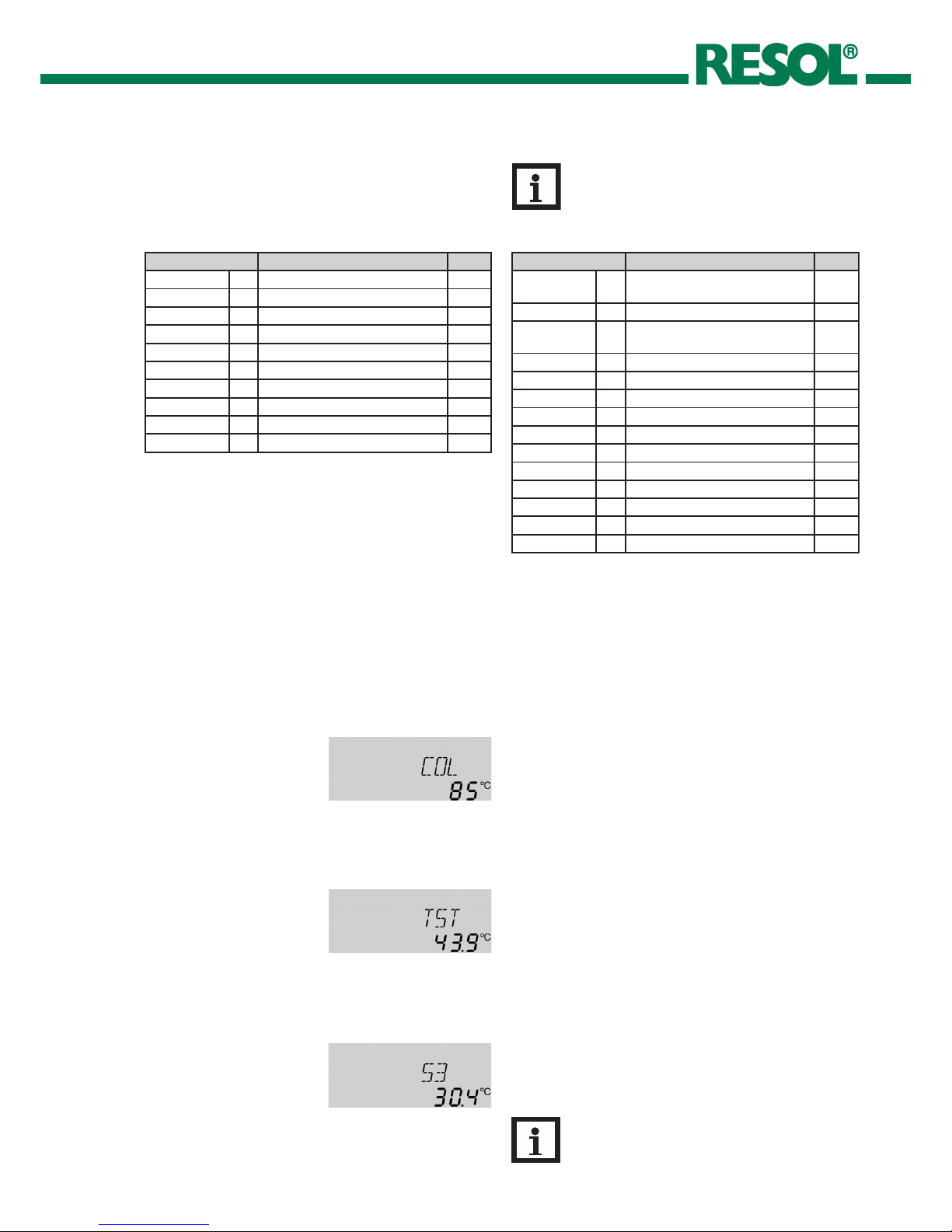
Display of collector temperature
Shows the current collector temperature.
• COL : collector temperature
COL:
collector temperature
display range:
-40 ... +260 °C
-40 ... +500 [°F]
Display of tank temperature
Shows the current tank temperature.
• TST : tank temperature
TST:
tank temperature
display range:
-40 ... +260 °C
-40 ... +500 [°F]
Display sensor 3
Shows the current temperature of the additional sensor
(without control function).
• S3 : temperature sensor 3
S3:
sensor temperature
display range:
-40 ... +260 °C
-40 ... +500 [°F]
D = Display
C = Control parameter
C* = Corresponding channel is available when the corres-
ponding option is enabled.
Channel Designation Page
OCX C option collector cooling
collector
12
CMX C* maximum temperature collector 12
OCN C option minimum limitation
collector
13
CMN C* minimum temperature collector 13
OCF C option antifreeze collector 13
CFR C* antifreeze temperature collector 13
OREC C option recooling 13
O TC C option tube collector 13
FMAX C maximum flow rate 14
MEDT C antifreeze type 14
MED% C antifreeze concentration 14
UNIT C unit 14
LANG C language 14
DSAL 1.00 C version number
Note:
Only if the temperature sensor is connected,
will S3 be displayed!
4.2 Displayandadjustmentvalues
DeltaSol® AL
| 10
© RESOL 10341 deltasol_al.monus.indd
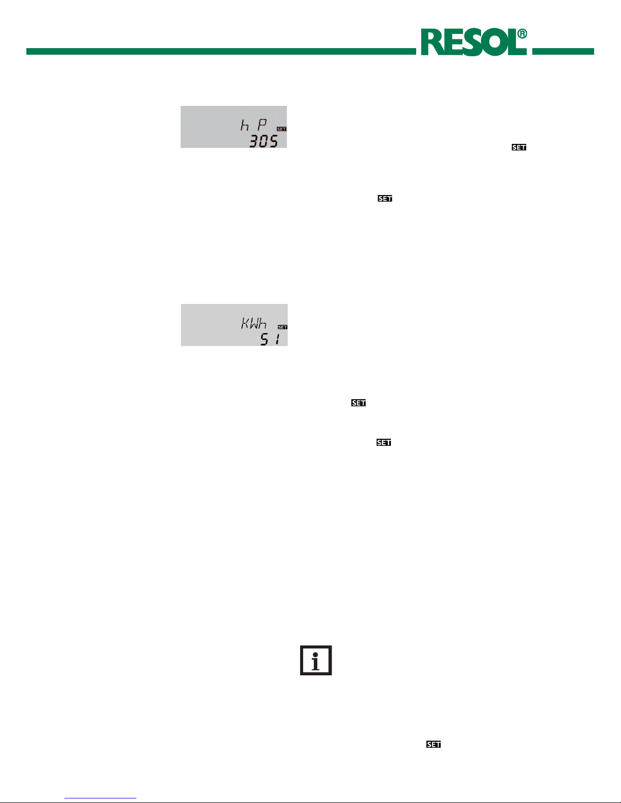
Operating hours counter
The operating hours counter accumulates the solar operating hours (h P) of the relay. Full hours are displayed.
The accumulated operating hours can be set back to zero.
As soon as one operating hours channel is selected, the
symbol is displayed.
Î In order to access the RESET-mode of the counter,
press the SET (3) button for approx. two seconds.
The display symbol
will flash and the operating hours
will be set to zero.
Î Confirm the reset with the SET button in order to
finish the reset.
In order to interrupt the RESET-process, do not press a
button for about five seconds. The display returns to the
display mode.
h P:
operating hours counter
display channel
kWh/MWh:
heat quantity in kWh / MWh
display channel
Information on flow rate, antifreeze (-/concentration) and
the temperature difference between the reference sensors
S1 (flow) and S2 (return) are used for determining the heat
quantity delivered. It is shown in kWh in the channel kWh
and in MWh in the channel MWh . The overall heat quantity
results from the sum of both values.
The accumulated heat quantity can be set back to zero. As
soon as one of the display channels of the heat quantity is
selected, the
symbol flashes.
Î In order to access the RESET-mode of the counter,
press the SET (3) button for approx. two seconds.
The display symbol
will flash and the heat quantity will
be set to zero.
Î Confirm the reset with the SET button in order to
finish the reset.
In order to interrupt the RESET-process, do not press a
button for about five seconds. The display returns to the
display mode.
In order to access the adjustment mode, scroll down in the
display menu and press button 1 for approx. three seconds
after you have reached the last display item. If an adjustment
value is shown on the display, the
icon is displayed. Now,
you can access the adjustment mode by pushing button 3.
Note:
The adjustment values should only be altered
by qualified personnel. Otherwise, the system
may not function faultlessly!

DeltaSol® AL
11 |
© RESOL 10341 deltasol_al.monus.indd
CMX:
collector maximum temperature
adjustment range:
100 ... 190 °C
210 ... 380 [°F]
factory setting:
120 °C; 250 [°F]
hysteresis: 5 K (10 °Ra)
System cooling
When the adjusted maximum tank temperature is reached,
the system stagnates. As soon as the collector temperature reaches the adjusted maximum collector temperature
(CMX) the solar pump is activated until the collector
temperature is 5 K (10 °Ra) lower than the maximum temperature. The tank temperature may increase, but only up to
95 °C (200 °F) (emergency shutdown of the tank).
OCX:
option system cooling
adjustment range: OFF / ON
factory setting: OFF
Maximum tank temperature
Once the adjusted maximum temperature is exceeded, the
solar pump is switched off and further loading of the tank
is prevented to reduce scald risk or system damage. The
symbol is shown on the display.
S MX:
maximum tank temperature
adjustment range:
4 ... 95 °C
40 ... 200 [°F]
factory setting:
60 °C; 140 [°F]
hysteresis: 2 K (4 °Ra)
Collector temperature limitation for emergency
shutdown of the collector
If the adjusted collector emergency shutdown temperature
(EM) is exceeded, the controller switches off the solar
pump in order to protect the system against overheating.
The factory setting is 140 °C (280 °F) but it can be changed
within the adjustment range of 110 ... 200 °C (230 ... 400 °F).
(flashing) is shown if EM is exceeded.
EM:
collector temperature limitation
adjustment range:
110 ... 200 °C
230 ... 400 [°F]
factory setting:
140 °C; 280 [°F]
hysteresis: 10 K (20 °Ra)
Note:
The controller is also equipped with a nonadjustable emergency switch-off if the tank reaches
95 °C (200 °F).
∆T-regulation
DT O:
switch-on temperature difference
adjustment range:
1.0 ... 20.0 K
2.0 ... 40.0 [°Ra]
factory setting:
6.0 K; 8.0 [°Ra]
If the switch-on difference (DT O) is reached, the pump
is activated. If the temperature difference falls below the
adjusted switch-off temperature difference (DT F) the
controller switches off.
Note:
The switch-on temperature difference must be
at least 0.5 K (1 °Ra) higher than the switch-off
temperature difference.
DTF:
switch-off temperature difference
adjustment range:
0.5 ... 19.5 K
1.0 ... 39.0 [°Ra]
factory setting:
4.0 K; 8.0 [°Ra]
DeltaSol® AL
| 12
© RESOL 10341 deltasol_al.monus.indd
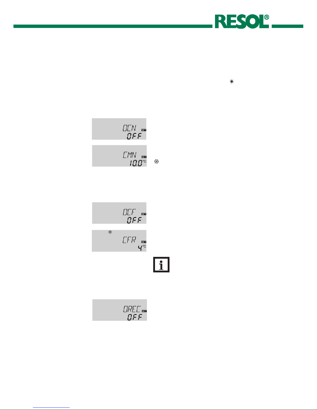
CMN:
collector minimum temperature
adjustment range:
10 ... 90 °C
50 ... 200 [°F]
factory setting:
10 °C; 50 [°F]
Option collector minimum limitation
OCN:
collector minimum limitation
adjustment range: OFF / ON
factory setting: OFF
The collector minimum limitation option prevents the solar
pump from being switched on too often at low collector
temperatures. When this option is activated, the collector
minimum temperature can be adjusted.
The collector minimum temperature is the temperature
which must be exceeded for the solar pump (R1) to switch
on. If the temperature falls below the minimum temperature,
(flashing) is shown.
CFR:
antifreeze temperature
adjustment range:
-10 ... 10 °C
10 ... 50 [°F]
factory setting:
4.0 °C; 40 [°F]
Antifreezeoption
OCF:
antifreeze function
adjustment range: OFF / ON
factory setting: OFF
The antifreeze function activates the loading circuit between
the collector and the tank when the temperature falls below
the adjusted antifreeze temperature at the collector sensor.
This will protect the fluid against freezing or coagulating.
When this option is activated, the antifreeze temperature
can be adjusted.
If the adjusted antifreeze temperature is exceeded by 1 °C
(2 °Ra), the loading circuit will be deactivated.
Option recooling
If the adjusted maximum tank temperature (S MX) is
reached, the controller keeps the solar pump running in
order to prevent the collector from being overheated.
The tank temperature may increase, but only up to 95 °C
(200 °F) (emergency shutdown of the tank).
If the tank temperature is higher than the maximum tank
temperature (S MX) and if the collector temperature is at
least 5 K (10 °Ra) below the tank temperature, the solar
system remains activated until the tank is cooled down
below the adjusted maximum tank temperature (S MX)
via the collec tor and the pipework.
OREC:
option recooling
adjustment range: OFF / ON
factory setting: OFF
Note:
Since this function uses the limited heat quantity
of the tank, the antifreeze function should be
used in regions with few days of temperatures
around the freezing point.
If the OREC option is additionally activated:
If the tank temperature is higher than the maximum tank
temperature (S MX) and if the collector temperature is at
least 5 K (10 °Ra) below the tank temperature, the solar
system remains activated until the tank is cooled down
below the adjusted maximum temperature (S MX) via the
collector and the pipework.
If the system cooling function is activated,
(flashing) is shown.
Due to the cooling function, the system will have a longer
operation time on hot summer days and guarantees thermal
relief of the collector field and the heat transfer fluid.

DeltaSol® AL
13 |
© RESOL 10341 deltasol_al.monus.indd
Evacuated tube collector function
If the controller detects an increase in collector temperature by 2 K (4 °Ra) compared to the previously stored collector temperature, the solar pump will be switched-on for
about 30 seconds in order to detect the fluid temperature.
The current collector temperature will be saved as a new
reference value. If the measured temperature (new reference value) is exceeded by 2 K (4 °Ra), the solar pump will
run for 30 seconds. If the switch-on difference between the
collector and the tank is exceeded during the runtime of
the solar pump, the controller will automatically switch to
solar loading.
If the collector temperature decreases by 2 K (4 °Ra) during
a loading break, the switch-on value for the evacuated tube
collector function will be recalculated.
O TC:
tube collector function
adjustment range: OFF / ON
factory setting: OFF
Language
In this adjustment channel the menu language can be chosen.
• dE : German
• En : English
• It : Italian
• Fr : French
LANG:
language selection
adjustment range: dE, En, It, Fr
factory setting: En
Temperature units
In this adjustment channel the temperature unit can be
chosen. The unit can be switched between °C and °F during operation.
Temperatures and temperature differences in °C and K are
displayed with the unit. If the indication is set to °F and °Ra,
the units are not displayed.
UNIT:
Temperature unit
adjustment range: °C, °F
factory setting: °C
Energy metering
Energy metering is possible if a flow gauge is used.
Î Read the flow rate (l /min) from the flow gauge and
adjust it in the FMAXchannel.
Î Adjust the antifreeze type and concentration of the
heat transfer fluid in the channels MEDT and MED%.
Antifreezetype:
0 : water
1 : propylene glycol
2 : ethylene glycol
3 : Tyfocor
®
LS / G-LS
FMAX:
flow rate in l/min
adjustment range: 0 ... 20
in 0.1 steps
factory setting:: 6.0
MEDT:
antifreeze type
adjustment range: 0 ... 3
factory setting: 1
MED%:
concentration of antifreeze
in (Vol-) %
MED% is “hidden” when MEDT
0 or 3 is used
adjustment range: 20 ... 70
factory setting: 45
°C

DeltaSol® AL
| 14
© RESOL 10341 deltasol_al.monus.indd
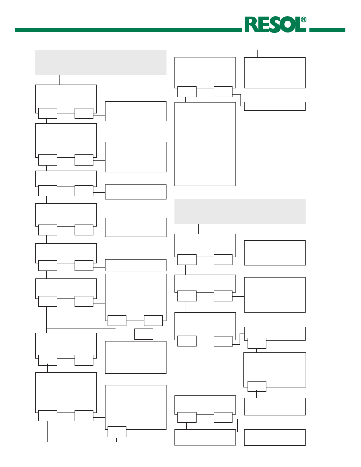
5. Troubleshooting
Operating control lamp off.
Check the power supply. Is it disconnected?
no
The fuse of the controller
could be blown. It can be
replaced after the front
cover has been removed
(spare fuse is enclosed in
the fuse holder).
Operating control lamp flashes red. The symbol and
the are shown.
Sensor fault. An error code instead of
a temperature is shown on the sensor
display channel.
-88.8888.8
Cab le i s broke n.
Check the cable.
Short-circuit.
Check the cable.
Disconnected Pt1000 temperature sen sors
can be checked with an ohmmeter. In the
following table, the resistance values
corresponding to different temperatures
are listed.
yes
Check the supply line and
reconnect it.
If a malfunction occurs, an error code will be indicated on
the display by means of symbols (see chap. 3.2.2).
Operating control lamp
Symbols
Fuse holder
The controller is protected by a fuse. The fuse holder (which
also holds the spare fuse) becomes accessible when the
cover is removed. To replace the fuse, pull the fuse holder
from the base.
°C °F Ω °C °F Ω
-10 14 961 55 131 1213
-5 23 980 60 140 1232
0 32 1000 65 149 1252
5 41 1019 70 158 1271
10 50 1039 75 167 1290
15 59 1058 80 176 1309
20 68 1078 85 185 1328
25 77 1097 90 194 1347
30 86 1117 95 203 1366
35 95 1136 100 212 1385
40 104 1155 105 221 1404
45 113 1175 110 230 1423
50 122 1194 115 239 1442
Resistance values of the Pt1000 temperature sensors

DeltaSol® AL
15 |
© RESOL 10341 deltasol_al.monus.indd
Pu mp starts for a sh ort mo men t, swit che s on/ off
again, etc.
Is the temperature difference at the controller
too small?
no yes
Wrong position of the
collector sensor?
yes
Change ∆Ton and ∆Toff
correspondingly.
Mount the collector sensor at solar flow (warmest
collector output); use the
immersion sleeve of the
respective collector.
Pump starts up very late.
The temperature difference between the tank and the collector increases enormously during operation; the collector
circuit cannot divert the heat.
Collector circuit pump
defective?
no yes
Heat exchanger calcified?
yes
Check / replace it
Decalify it
no
Heat exchanger blocked?
yesno
Clean it
Heat exchanger too
small?
yes
Replace with correctly
sized one
no
Plausibility control of the
tube collector function
Change ∆Ton and ∆Toff
correspondingly
Switch-on temperature
difference ∆Ton too
large?
no yes
Non -ide al posi tion of
col lecto r sen sor (e.g.
flatscrew sensor instead
of sensor in immersion
sleeves?)
o.k.no
Pump is overheated, but no heat transfer from the collector to the tank, flow and return have the same temperature; perhaps also bubbles in the pipes
Vent the system; in crease
sys tem pressu re to at
least static primary pressure plus 0.5 bar (7.25 psi);
if necessary increase the
pressure, switch the pump
on and off for a short time
Air in the system?
no yes
Is the collector circuit
blocked at the dirt trap?
yes
Clean the dirt trap
5.1Various
Activate tube collector
function if necessary.
yes
o.k.
DeltaSol® AL
| 16
© RESOL 10341 deltasol_al.monus.indd
Tanks cool down at night.
Does the collector
circuit pump run during
the night?
no yes
Check controller.
At nig ht, the colle ctor
tem per ature is high er
than the outdoor temperature.
no yes
Ch eck th e non-re turn
valve in flow and return
pipe with regard to the
functional efficiency.
Sufficient tank insulation?
yes no
Increase insulation.
Insulation close enough
to the tank?
yes no
Replace insulation or increase it.
Are the tank connections
insulated?
yes no
Insulate the connections.
Warm water flows
upwards?
no yes
Change connection and
let the water flow sidewards or through a siphon
(bow downwards); less
tank losses now?
Does warm water circulation run for a very long
time?
no yes
Use the circulation pump
with timer and switch-off
thermostat (energy efficient circulation)
The solar circuit pump does not run although the collector
is significantly warmer than the tank.
Does the operating control lamp flash?
yes no
Does the pump start up
in manual operation?
yes
No current; check fuses
/ replace them and check
power supply.
The adjusted temperature
difference for starting the
pump is to high; choose a
value which makes more
sense.
no
Is the pump current released by the controller?
yes
Is the pump stuck?
Turn the pump shaft using
a screwdriver; now passable?
Pump is defective - replace it
Are the controller fuses
o.k.?
Controller might be defective - replace it.
no
yes
no
no yes
Replace the fuses.
Circul ation pum p a n d
blocking valve should be
switched off for one night;
less tank losses?
yes no
Check whether the pumps
of the after-heating circuit runs at night, check
non-return valve; problem
solved?
no
no yes
o.k.
Ch eck th e non-re turn
valve in warm water circulation – o.k.?
yes no
Further pumps which are
connected to the solar
tank must also be checked.
The gravity circu lation in
the circulation line is too
strong; insert a stronger
valve in the non-return
valve or an electric 2-port
valve behind the circulation pump; in pump operation, the 2-port valve
is open, other wise it is
closed, conect pump and
2-por t valve in parallel;
activate circulation again!
Clean or replace
a
a b
b
DeltaSol® AL
17 |
© RESOL 10341 deltasol_al.monus.indd
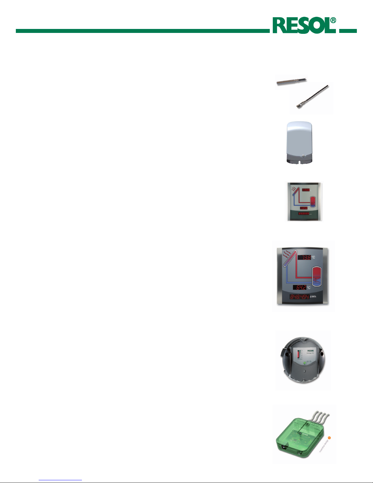
6. Accessories
Overvoltage protection device
In order to avoid overvoltage damage at collector sensors (e.g. caused by local lightning
storms), we recommend the overvoltage protection RESOL SP10.
RESOL SP10 Article no.: 180 110 70
Sensors
Our product range includes high-precision platinum temperature sensors, flatscrew sensors,
outdoor temperature sensors, indoor temperature sensors, cylindrical clip-on sensors, also
as complete sensors with sensor wells.
For more information, see our catalogue and price list.
Smart Display SD3
The RESOL Smart Display is designed for simple connection to RESOL controllers with
RESOL VBus
®
. It is used for visualizing data issued by the controller: collector temperature,
storage temperature and energy yield of the solar thermal system. The use of high-efficient
LEDs and filter glass assures a high optical brilliance and good readability even in poor
visibility conditions and from a larger distance. An additional power supply is not required.
RESOL SD3 Article no.: 180 004 93
Large Display GA3
The RESOL Large Display GA3 is designed for simple connection to RESOL controllers via
the RESOL VBus
®
. It is used for visualizing the data issued by the controller: collector and
tank temperature as well as heat quantity produced in the solar system.
The use of high-efficient LEDs and antireflective filter glass assures a high optical brilliance
and good readability - even in poor lighting conditions and at a larger distance.
RESOL GA3 Article no.: 180 006 53
DL2 Datalogger
This additional module enables the acquisition and storage of large amounts of data (such
as measuring and balance values of the solar system) over a long period of time. The DL2
can be configured and read-out with a standard internet browser via its integrated web
interface. For transmission of the data stored in the internal memory of the DL2 to a PC,
an SD card can be used.
The DL2 is appropriate for all controllers with RESOL VBus
®
. It can be connected directly
to a PC or router for remote access and thus enables comfortable system monitoring for
yield monitoring or for diagnostics of faults.
RESOL DL2 Article no.: 180 007 10
VBus®/USBinterfaceadapter
The new VBus
®
/ USB interface adapter is the interface between the controller and a
personal computer. With its standard mini-USB port it enables a fast transmission of system
data for processing, visualizing and archiving as well as the parameterization of the controller
via the VBus®. A full version of the RESOL ServiceCenter software is included.
RESOLVBus
®
/USBinterfaceadapter Article no.: 180 008 50

DeltaSol® AL
| 18
© RESOL 10341 deltasol_al.monus.indd
Notes

DeltaSol® AL
19 |
© RESOL 10341 deltasol_al.monus.indd
Notes

DeltaSol® AL
| 20
© RESOL 10341 deltasol_al.monus.indd
Distributed by:
RESOL-ElektronischeRegelungenGmbH
Heiskampstraße 10
45527 Hattingen / Germany
Tel.: +49 (0) 23 24 / 96 48 - 0
Fax: +49 (0) 23 24 / 96 48 - 755
www.resol.de
info@resol.de
Please note:
The design and the specifications can be changed without prior notice.
The illustrations may differ from the original product.
Reprinting / copying
This mounting- and operation manual including all parts
is copyrighted. Another use outside the copyright requires
the approval of RESOL - Elektronische Regelungen GmbH.
This especially applies for copies, translations, microfilms and the storage into electronic systems.
Editor: RESOL - Elektronische Regelungen GmbH
Important notice:
The texts and drawings in this manual are correct to the
best of our knowledge. As faults can never be excluded,
please note: Your own calculations and plans, under con sideration of the current standards should only be basis for your
projects. We do not offer a guarantee for the completeness of
the drawings and texts of this manual - they only represent
some examples. They can only be used at your own risk.
No liability is assumed for incorrect, incomplete or false
information and / or any resulting damages.
 Loading...