

Page 1
*11206694*
11206694
Thank you for buying this product.
Please read this manual carefully to get the best performance from this unit.
Please keep this manual safe.
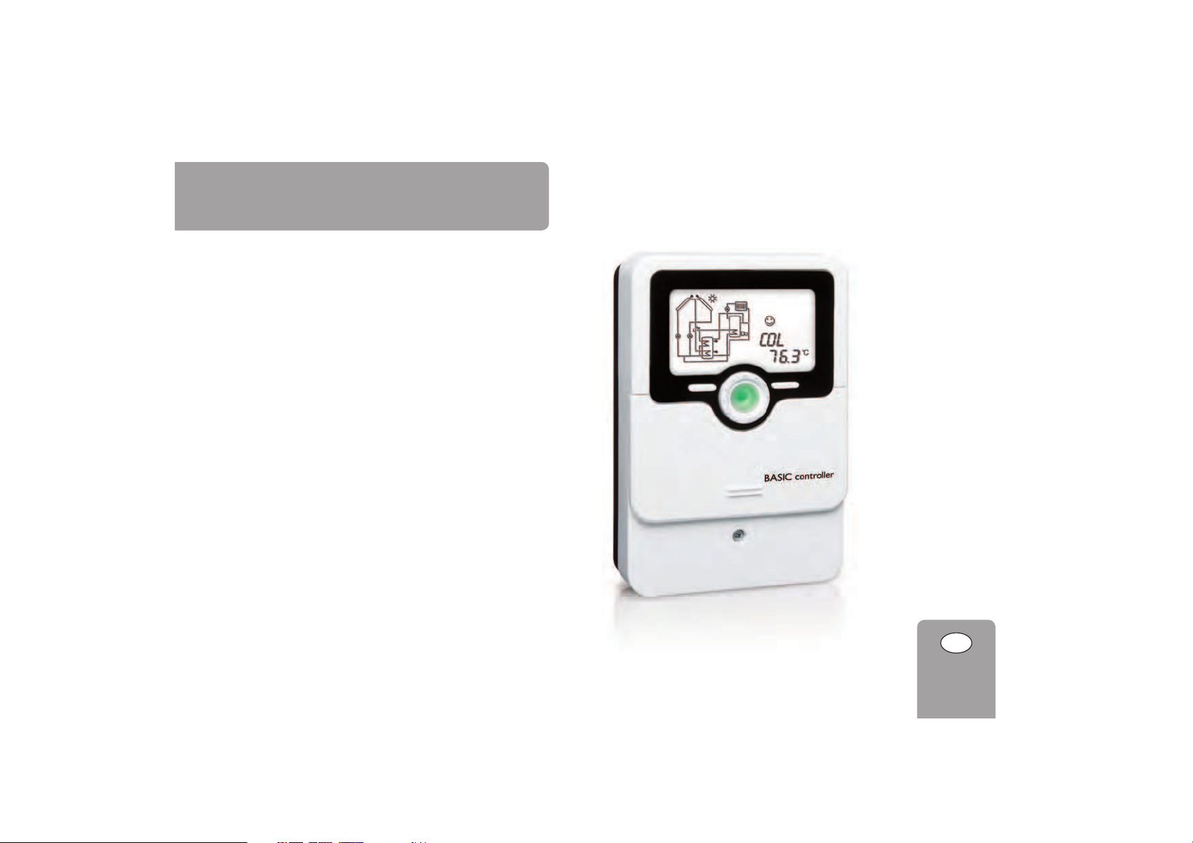
BASIC controller
Manual
en
Solar controller
Manual for the
specialised craftsman
Installation
Operation
Functions and options
Troubleshooting
Page 2
2
en
© 20141209_11206694_HR_Solar_BASIC_controller.monen
Safety advice
Please pay attention to the following safety advice in order to avoid danger and
damage to people and property.
Instructions
Attention must be paid to the valid local standards, regulations and directives!
Information about the product
Proper usage
The solar controller is designed for electronically controlling standard solar thermal
systems and heating systems in compliance with the technical data specified in this
manual.
Improper use excludes all liability claims.
CE Declaration of conformity
The product complies with the relevant directives and is therefore
labelled with the CE mark. The Declaration of Conformity is available
upon request, please contact the manufacturer.
Note
Strong electromagnetic fields can impair the function of the controller.
Î Make sure the controller as well as the system are not exposed to
strong electromagnetic fields.
Subject to technical change. Errors excepted.
Target group
These instructions are exclusively addressed to authorised skilled personnel.
Only qualified electricians should carry out electrical works.
Initial installation must be effected by the system owner or qualified personnel
named by the system owner.
Description of symbols
WARNING!
Warnings are indicated with a warning triangle!
Î They contain information on how to avoid the danger
described.
Signal words describe the danger that may occur, when it is not avoided.
• WARNING means that injury, possibly life-threatening injury, can occur.
• ATTENTION means that damage to the appliance can occur.
Note
Notes are indicated with an information symbol.
Î Arrows indicate instruction steps that should be carried out.
Disposal
• Dispose of the packaging in an environmentally sound manner.
• Dispose of old appliances in an environmentally sound manner. Upon request we
will take back your old appliances bought from us and guarantee an environmentally sound disposal of the devices.
Page 3
3
en
1 Overview .............................................................................................. 4
2 Installation ...........................................................................................5
2.1 Montage .........................................................................................................................5
2.2 Electrical connection ...................................................................................................5
2.4 System overview ..........................................................................................................6
2.3 Data communication / Bus ..........................................................................................6
2.5 Systems ...........................................................................................................................7
3 Operation and function ....................................................................10
3.1 Buttons and adjustment dial ....................................................................................10
3.2 Microbuttons for manual mode and holiday mode ............................................10
3.3 Control lamp ...............................................................................................................11
3.4 Menu structure ...........................................................................................................11
3.5 Selecting menu points and adjusting values .........................................................11
3.6 Resetting balance values ...........................................................................................12
4 System-Monitoring-Display .............................................................. 12
4.1 System screen .............................................................................................................12
4.2 Further indications ....................................................................................................13
BASIC controller
With its versatile software, the BASIC controller can control even complex systems
easily and reliably. 3 pre-configured system layouts facilitate the commissioning. The
operation via 2 main buttons and 1 adjustment dial, the Lightwheel
®
, still follows
the well-known operating concept. The multicoloured LED, integrated in the Light-
5 Status level / Measurement values ....................................................14
6 Balance values....................................................................................15
7 Commissioning ..................................................................................15
8 Indications, functions and options....................................................17
8.1 Status level ...................................................................................................................17
8.2 Menu overview ...........................................................................................................20
9 Messages .............................................................................................36
10 Troubleshooting .................................................................................37
11 Accessories ........................................................................................40
11.1 Sensors and measuring instruments ......................................................................41
11.2 VBus
®
accessories ......................................................................................................41
11.3 Interface adapters ......................................................................................................41
12 Index ...................................................................................................42
Contents
wheel®, offers many possibilities to signal different system states. 2 microbuttons for
quick access to the manual mode and the holiday function are located underneath
the slidable housing cover, the slider.
Page 4
4
en
1 Overview
• 2 relay outputs (incl. 1 potential-free extra-low voltage relay)
• 4 inputs for Pt1000, Pt500 or KTY temperature sensors
• 1 V40 impulse input
• 1 PWM output for speed control of high-efficiency pumps
• 3 systems
• Automatic function control according to VDI 2169
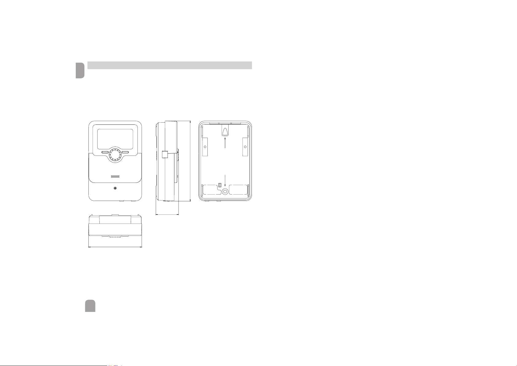
110
166
130
47
Technical data
Inputs: 4 inputs for Pt1000, Pt500 or KTY temperature sensors, 1 V40 impulse
input
Outputs: 1 semiconductor relay, 1 potential-free extra-low voltage relay, 1 PWM
output (switchable to 0-10 V)
Switching capacity:
1 (1) A 240 V~ (semiconductor relay)
1 (1) A 30 V
(potential-free relay)
Total switching capacity: 2 A 240 V~
Power supply: 100 … 240 V~ (50 … 60 Hz)
Supply connection: type Y attachment
Power consumption < 1 W (standby)
Mode of operation: type 1.B.C.Y action
Rated impulse voltage: 2.5 kV
Data interface: VBus
®
VBus® current supply: 60 mA
Functions: operating hours counter, tube collector function, pump speed control,
heat quantity measurement, adjustable system parameters and optional functions
(menu-driven), balance and diagnostics function, function control according to VDI
2169
Housing: plastic, PC-ABS and PMMA
Mounting: wall mounting, also suitable for mounting into patch panels
Indication / Display: System-Monitoring-Display, for visualisation of the systems,
16-segment-display, 8 symbols for indication of the system status, Lightwheel
®
(ad-
justment dial) and background illumination
Operation: 4 push buttons and 1 Lightwheel
®
Protection type: IP 20 / DIN EN 60529
Protection class: I
Ambient temperature: 0 … 40 °C
Degree of pollution: 2
Dimensions: 110 x 166 x 47 mm
Page 5
en
5
InstallationIndications, functions and optionsMessages Commissioning Operation and function
2 Installation
2.1 Montage
WARNING!
Electric shock!
Upon opening the housing, live parts are exposed!
Î Always disconnect the device from power supply
before opening the housing!
Note
Strong electromagnetic fields can impair the function of the controller.
Î Make sure the controller as well as the system are not exposed to
strong electromagnetic fields.
The device must only be located in dry interior rooms.
The controller must additionally be supplied from a double pole switch with contact
gap of at least 3 mm.
Please pay attention to separate routing of sensor cables and mains cables.
In order to mount the device to the wall, carry out the following steps:
Î Unscrew the crosshead screw from the cover and remove it along with the
cover from the housing.
Î Mark the upper fastening point on the wall. Drill and fasten the enclosed wall
plug and screw leaving the head protruding.
Î Hang the housing from the upper fastening point and mark the lower fastening
points (centres 130 mm).
Î Insert lower wall plugs.
Î Fasten the housing to the wall with the lower fastening screw and tighten.
Î Carry out the electrical wiring in accordance with the terminal allocation (see
page 5).
Î Put the cover on the housing.
Î Attach with the fastening screw.
2.2 Electrical connection
ATTENTION!
ESD damage!
Electrostatic discharge can lead to damage to electronic components!
Î Take care to discharge properly before touching the
inside of the device! To do so, touch a grounded surface such as a radiator or tap!
WARNING!
Electric shock!
Upon opening the housing, live parts are exposed!
Î Always disconnect the device from power supply
before opening the housing!
Note
Connecting the device to the power supply must always be the last step
of the installation!
Note
The pump speed must be set to 100 % when auxiliary relays or valves are
connected.
The controller is supplied with power via a mains cable. The power supply of the
device must be 100 … 240 V~ (50 … 60 Hz).
The controller is equipped with 2 relays in total to which loads such as pumps,
valves, etc. can be connected:
• Relay 1 is a semiconductor relay, designed for pump speed control:
Conductor R1
Neutral conductor N
Protective conductor
• Relay 2 is a potential-free extra-low voltage relay
Depending on the product version, mains cables and sensor cables are already connected to the device. If that is not the case, please proceed as follows:
Connect the temperature sensors (S1 to S4) to the following terminals with
either polarity:
S1 = Sensor 1 (collector sensor)
S2 = Sensor 2 (store sensor base)
S3 = Sensor 3 (e. g. store sensor top)
S4 = Sensor 4 (e. g. washing machine)
A V40 flowmeter can be connected to the terminals V40 and GND (either po-
larity).
Page 6
en
6
Installation Indications, functions and options MessagesCommissioningOperation and function
2.4 System overview
The terminal marked PWM is a control output for a high-efficiency pump (convertible to 0-10 V signal outputs, see page 10).
The mains connection is at the terminals:
Neutral conductor N
Conductor L
Protective conductor
Note
The connection depends on the system layout selected (see page 6).
Note
For more details about the commissioning procedure see page 15.
2.3 Data communication / Bus
The controller is equipped with a VBus
®
for data transfer and energy supply to
external modules. The connection is to be carried out at the terminals marked
VBus (any polarity).
One or more VBus
®
modules can be connected via this data bus, such as:
• DL2 Datalogger
• DL3 Datalogger
Furthermore, the controller can be connected to a PC or integrated into a net-
work via the VBus
®
/USB or VBus®/LAN interface adapter (not included). Different
solutions for visualisation and remote parameterisation are availabe on the website
www.resol.com.
Note
More accessories on page 40.
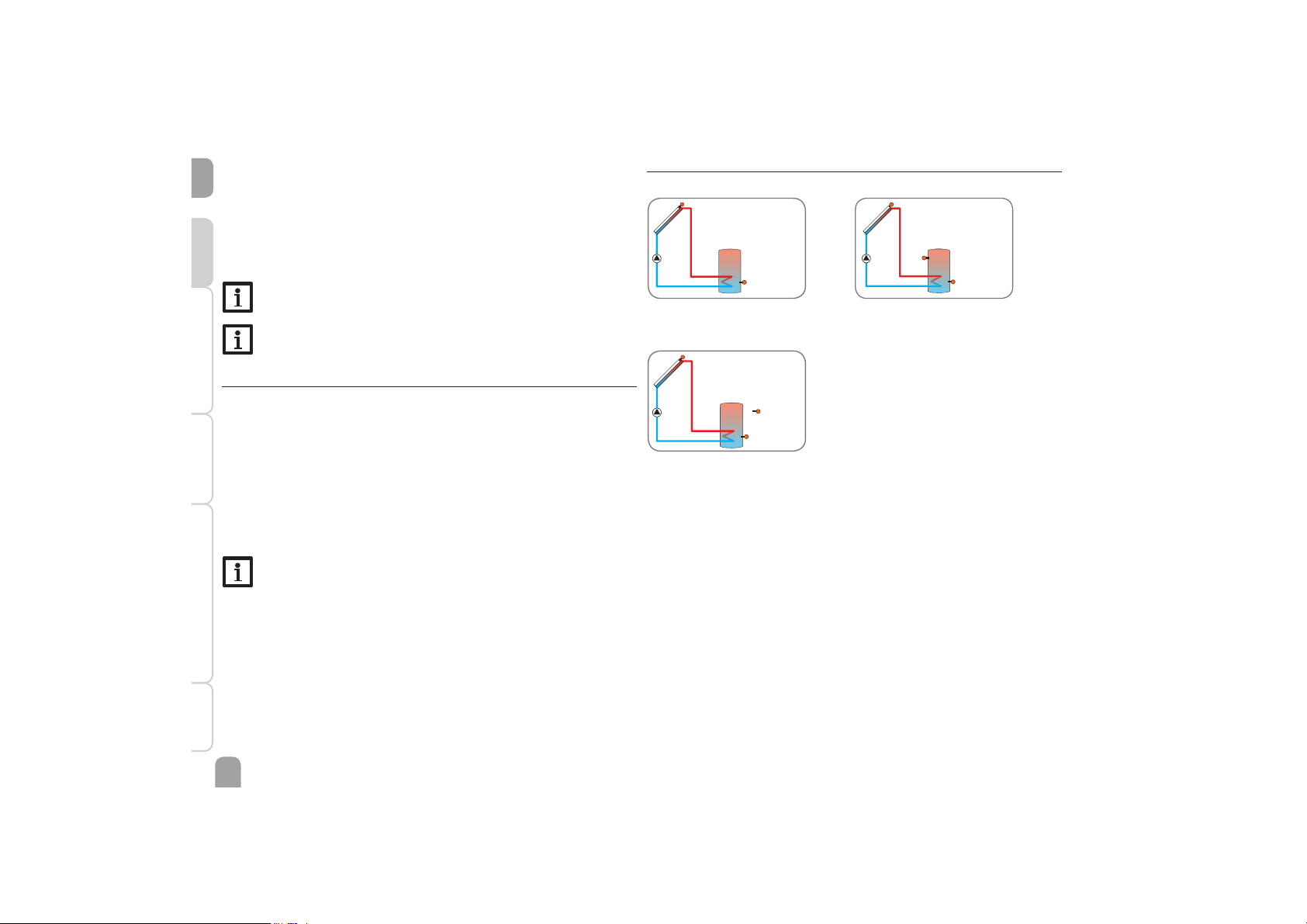
1
Solar system with 1 store (7)
3
Solar system with 1 store (9)
2
Solar system with 1 store and afterheating (8)
Page 7
en
7
InstallationIndications, functions and optionsMessages Commissioning Operation and function
2.5 Systems
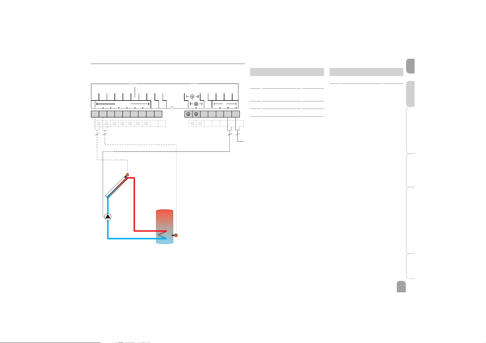
System 1: Standard solar system with 1 store
The controller calculates the temperature difference between collector sensor
S1 and store sensor S2. If the difference is larger than or identical to the adjusted
switch-on temperature difference, the pump (R1) will be switched on and the store
will be loaded until the switch-off temperature difference or the maximum store
temperature is reached.
Sensors
S1 Temperature
collector
1 / GND
S2 Temperature store
base
2 / GND
S3 Free 3 / GND
S4 Free 4 / GND
V40 Free V40 / GND
Relay
R1 Solar pump R1 / N / PE
R2 Free R2 / R2
S2
R1
S1
VBus
VBus
S5/V40
S3
S4
GND
Sensors
Relais
S2
S1
N
R1
L
R2
PWM A
0-10 V
R2
N N N N
R1 L
1 2 3 4
5 6 7 8 9
10 11
332
2
Mains
Page 8
en
8
Installation Indications, functions and options MessagesCommissioningOperation and function
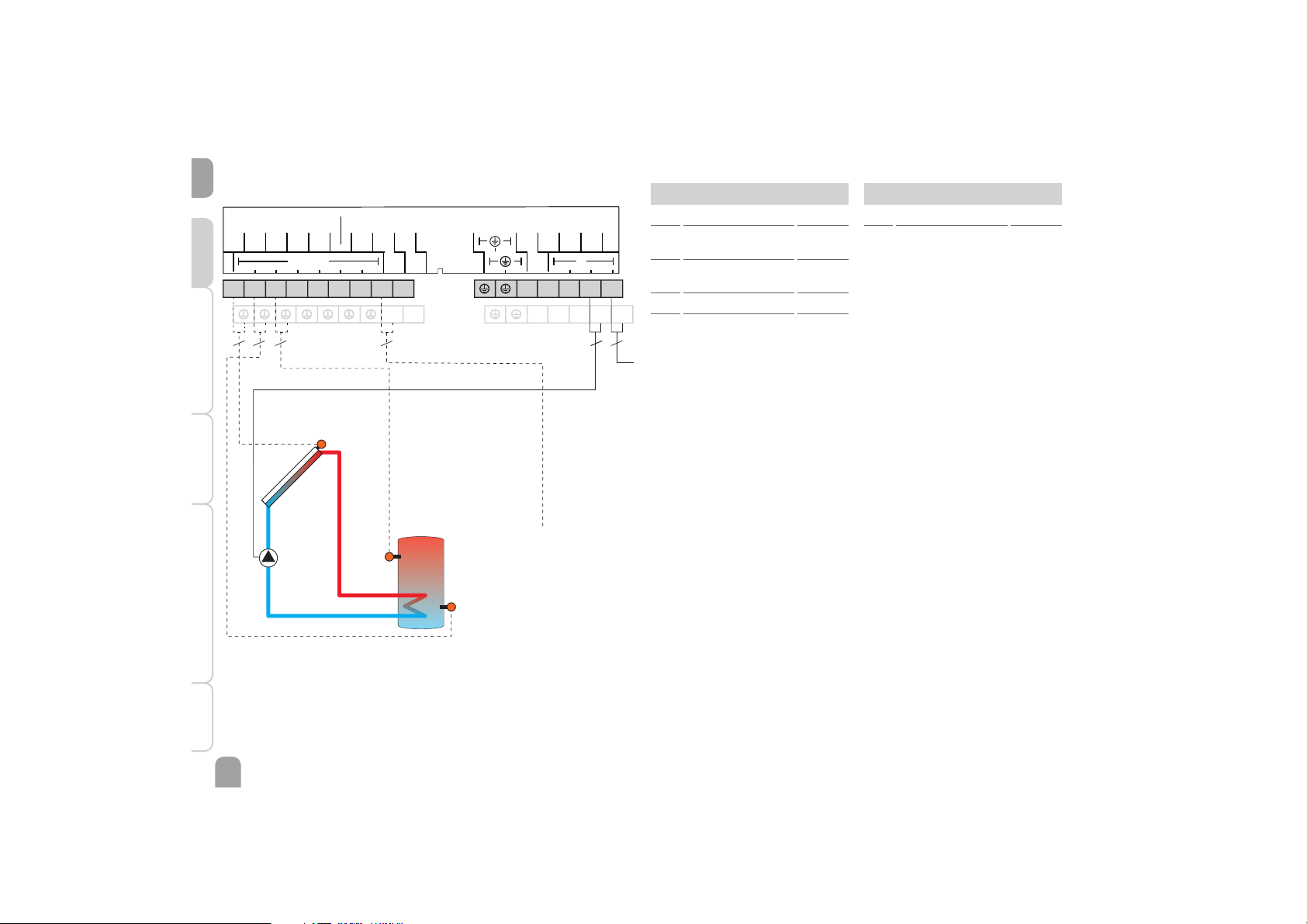
System 2: Solar system with 1 store and afterheating
The controller calculates the temperature difference between collector sensor
S1 and store sensor S2. If the difference is larger than or identical to the adjusted
switch-on temperature difference, the pump (R1) will be switched on and the store
will be loaded until the switch-off temperature difference or the maximum store
temperature is reached.
Afterheating (R2) can be carried out with a thermostat function (S3). If the value
at S3 reaches the switch-on temperature for the afterheating, the relay is switched
on. If the value exceeds the switch-off temperature for the afterheating, the relay
is switched off again.
R1
S2
S1
R2
VBus
VBus
V40
S3
S4
GND
Sensors
Relais
S2
S1
N
R1
L
R2
PWM A
0-10 V
R2
N N N N
R1 L
1 2 3 4
5 6 7 8 9
10 11
332
2 2
2
S3
Sensors
S1 Temperature collector 1 / GND
S2 Temperature store
base
2 / GND
S3 Temperature
afterheating
3 / GND
S4 Free 4 / GND
V40 Free 5 / GND
Relay
R1 Solar pump R1 / N / PE
R2 Afterheating R2 / R2
Mains
Page 9
en
9
InstallationIndications, functions and optionsMessages Commissioning Operation and function
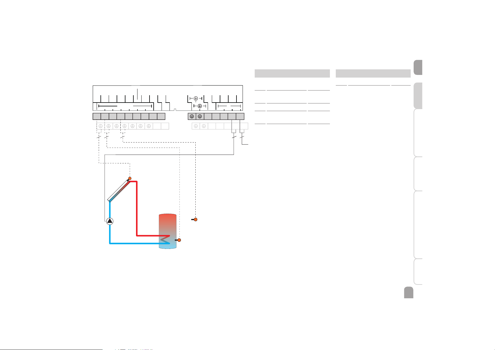
System 3: Standard solar system with 1 store
The controller calculates the temperature difference between collector sensor
S1 and store sensor S2. If the difference is larger than or identical to the adjusted
switch-on temperature difference, the pump (R1) will be switched on and the store
will be loaded until the switch-off temperature difference or the maximum store
temperature is reached.
Preheating of the washing machine inlet (R2) can be carried out with a thermostat
function. If the value at S4 reaches the switch-on temperature for the washing
machine function, the function will be switched on and the temperature will be
maintained at the desired value for the adjusted time by means of the valve. After
the adjusted time has elapsed, the relay will be deactivated for the same duration.
Sensors
S1 Temperature
collector
1 / GND
S2 Temperature store
base
2 / GND
S3 Free 3 / GND
S4 Temperature washing
machine inlet
4 / GND
V40 Free V40 / GND
Relay
R1 Solar pump R1 / N / PE
R2 Valve washing machine R2 / R2
S2
R1
S1
VBus
VBus
S5/V40
S3
S4
GND
Sensors
Relais
S2
S1
N
R1
L
R2
PWM A
0-10 V
R2
N N N N
R1 L
1 2 3 4
5 6 7 8 9
10 11
332
2
S4
2
Mains
Page 10
en
10
Installation Indications, functions and options MessagesCommissioningOperation and function
3 Operation and function
3.1 Buttons and adjustment dial
The controller is operated via 2 buttons and 1 adjustment dial (Lightwheel®) below
the display:
Left button (") - escape button for changing into the previous menu
Right button () - confi rming / selecting
Lightwheel
®
- scrolling upwards / scrolling downwards, increasing adjustment
values / reducing adjustment values
3.2 Microbuttons for manual mode and holiday mode
The controller is equipped with two microbuttons for quick access to the manual
mode and the holiday function. The microbuttons are located underneath the slidable housing cover, the slider.
Mircobutton : If the microbutton is briefl y pressed, relay 1 will be set to the
manual mode for 1 minute
Microbutton : The microbutton is used for activating the holiday function
(see 29). If the microbutton is pressed and held down for approx. 3 s, the adjustment channel DAYS appears, allowing to en-
ter the number of days for an absence. If the parameter is set to
a value higher than 0, the function becomes active using the adjustments that have previously been made in the H-DAY menu.
The days will be counted backwards at 00:00. If the value is set to
0, the function is deactivated.
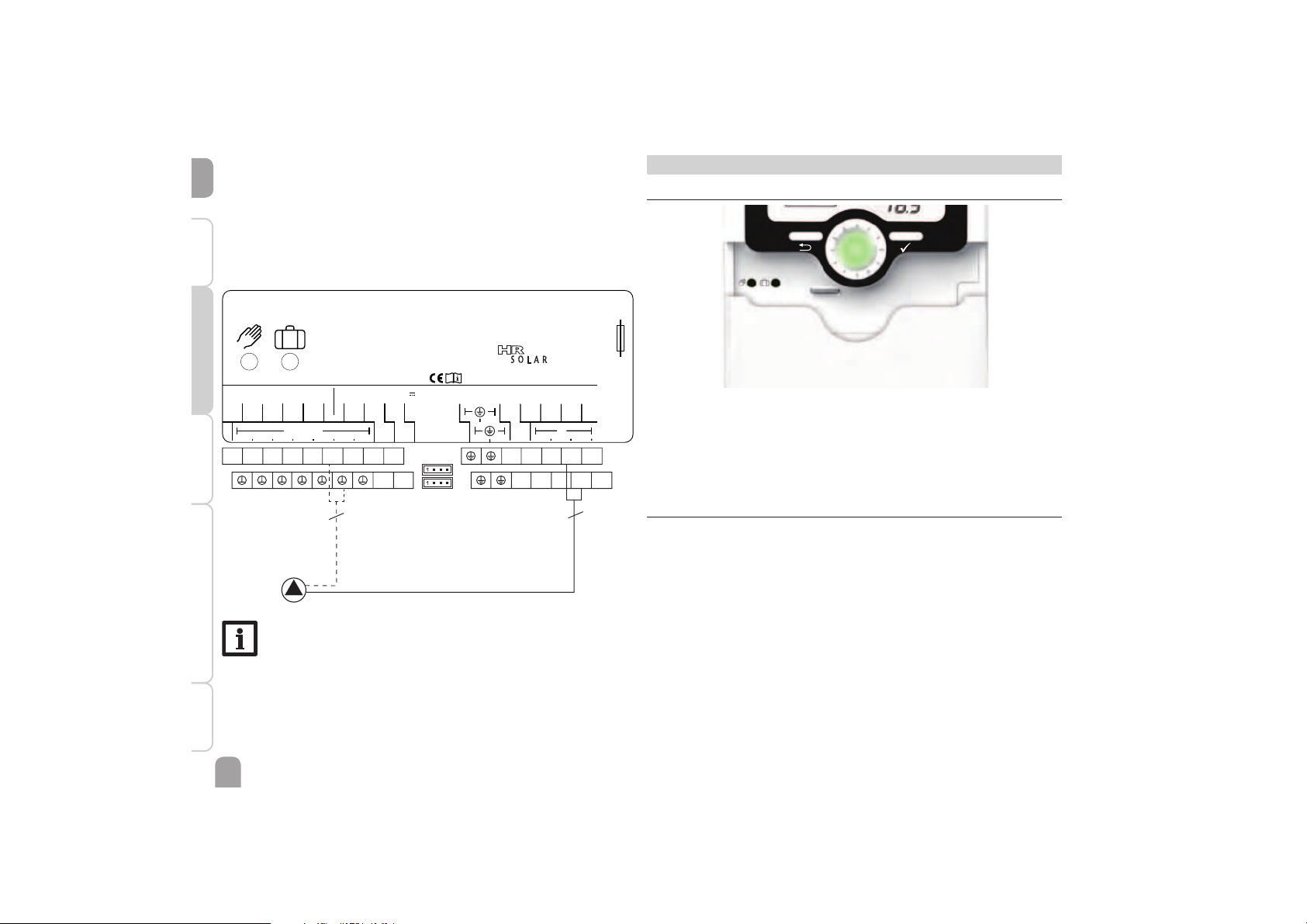
Electrical connection of a high-effi ciency pump ( HE pump)
Speed control of a HE pump is possible via a PWM signal / 0-10 V control. The pump
has to be connected to the relay (power supply) as well as to one of the PWM A/B
outputs of the controller. In the REL adjustment channel one of the PWM control
types as well as a relay have to be selected (see page 28).
N N N N
R3 R2 R1 L
1 2 3 4
5 6 7 8 9
10 11
3
2
VBus
VBus
V40
S3
S4
GND
SIMPLE CONTROLLER
NL-3151 XP Hoek van Holland
Sensors
S2
S1
100 ... 240 V
T1A
50-60 Hz
N
R1
L
R1|1 (1) A 240 V~R2|1 (1) A 30V
IP 20
R2
PWM A
0-10 V
R2
Note
For more information about relay control, see page 28.
Page 11
en
11
InstallationIndications, functions and optionsMessages Commissioning Operation and function
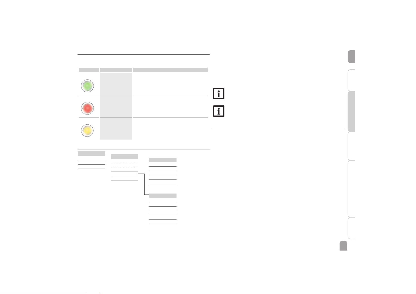
3.3 Control lamp
The controller is equipped with a multicolour LED in the centre of the Lightwheel
®
,
indicating the following states:
Colour Permanently shown Flashing
Green
Everything OK Manual mode: at least one relay HAND ON / min-
imum speed / maximum speed
Red
Sensor line break, sensor short circuit, fl ow rate
monitoring, overpressure, low pressure
Yellow
Holiday function
active
'T too high, night circulation, FL/RE interchanged,
store emergency temperature exceeded
3.4 Menu structure
Confi guration
DT O
DT F
DT S
S SET
S MAX
SMAXS
…
Menu level
BALAN
Adjustment level
SYS
LOAD
COL
…
Status level
TCOL
TSTB
TSTT
…
Balance values
h R1
h R2
DAYS
MAXS1
MINS1
…
The menu structure of the controller consists of 2 levels: the status level and the
menu level.
The status level consists of different display channels which indicate display values
and messages.
The menu level consists of the balance value menu and several menu items each of
which consist of sub-menus and adjustment channels.In order to activate or deactivate a function, it must be selected in the menu level. The display changes to the
adjustment menu in which all adjustments required can be carried out.
Note
Some of the menu items depend on the selected system and the adjusted
options. Therefore, they are only displayed if they are available.
Note
The abstract from the menu structure is for information on the structure
of the controller menu and is therefore not complete.
3.5 Selecting menu points and adjusting values
During normal operation of the controller, the display shows the status level with
the indication channels. If no button is pressed for 1 min, the display illumination
goes out. If no button is pressed for further 3 min, the display indicates the status
level.
Î Press any key to reactivate the display illumination.
Î In order to scroll through the display channels, turn the Lightwheel
®
.
Accessing the adjustment level:
Î Press the right button () for approx. 3 s.
The display changes to the adjustment level. All menus contain adjustment channels
and are marked with PUSH below the the menu item.
Î In order to access the desired menu, press the right button ().
Page 12
en
12
Installation Indications, functions and options MessagesCommissioningOperation and function
4 System- Monitoring-Display
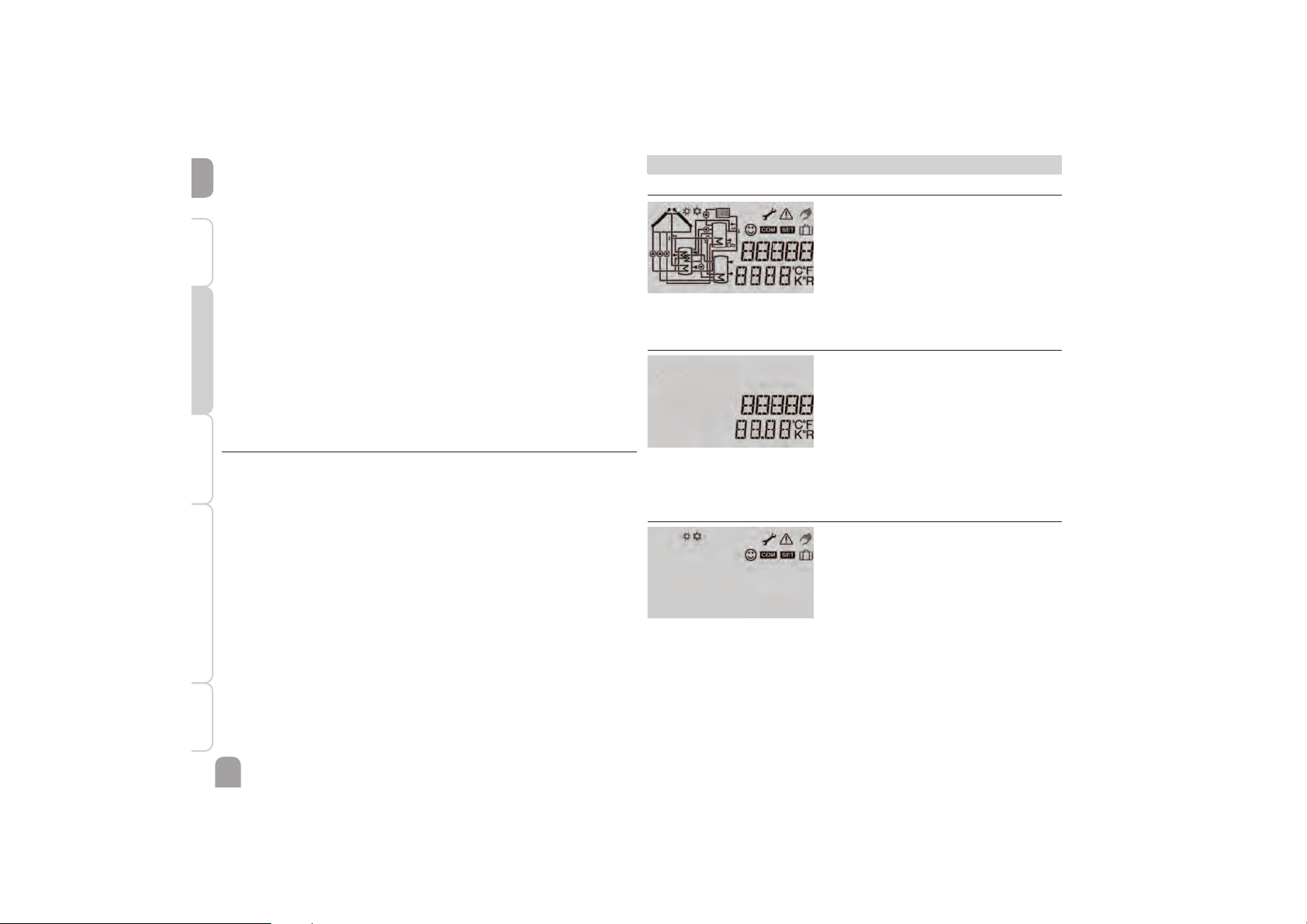
System-Monitoring- Display
The System-Monitoring-Display consists of 3 blocks: channel display, tool bar and
system screen.
Channel display
The channel display consists of 2 lines. The upper display line is an alphanumeric
16-segment display. In this line, mainly channel names and menu items are displayed.
In the lower 16-segment display, values are displayed.
Tool bar
The additional symbols in the tool bar indicate the current system state.
Selecting and adjusting options / functions
An option or function containing adjustment values are marked with PUSH.
Î In order to access the sub-menu of the option, select the option by turning the
Lightwheel
®
and press the right button ().
Î In order to activate an option, select ON. In order to deactivate it, select OFF.
The adjustment channels are characterised by the indication .
Î Select the desired adjustment channel by turning the Lightwheel
®
.
Î Confi rm your selection with the right button (). starts fl ashing (ad-
justment mode).
Î Adjust the value by turning the Lightwheel
®
.
Î Confi rm your selection with the right button (). permanently appears,
the adjustment has been saved.
BACK PUSH appears as the last display.
Î In order to get back to the menu selection, press the right button ().
If no button has been pressed within a couple of minutes, the adjustment is cancelled and the previous value is retained.
3.6 Resetting balance values
Heat quantity, operating hours of the relays as well as minimum and maximum
temperatures can be set back to zero. In order to reset a value, proceed as follows:
Î Select the desired value and press the right button (). starts fl ashing.
Î Turn the Lightwheel
®
anticlockwise.
The value is set back to 0.
Î Press the right button ().
The message DEL will be displayed.
Î Turn the Lightwheel
®
clockwise.
YES instead of NO will be displayed.
Î Confi rm your selection with the right button ().
The value will be set back to zero and the symbol will be permanently displayed.
In order to interrupt this process, press the left button (").
Page 13
en
13
InstallationIndications, functions and optionsMessages Commissioning Operation and function
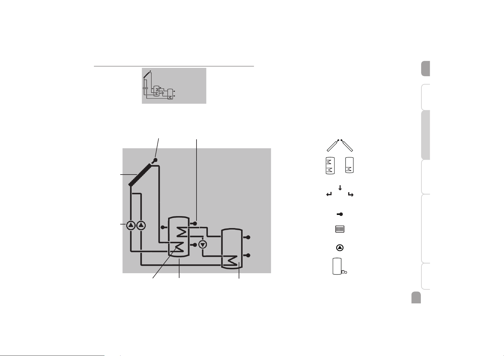
4.1 System screen
The system selected is indicated in the System-Monitoring-Display. It consists of
several system component symbols which are – depending on the current status of
the system – either flashing, permanently shown or hidden.
Sensor
Collector 1
Pumps
StoreStore heat exchanger Store 2
Sensor
Collectors
with collector sensor
3-port valve
Only the flow direction or
current switching position
is indicated.
Store 1 and 2
with heat exchanger
Pump
Heating circuit
(return preheating)
Afterheating
with burner symbol
Temperature sensor
Page 14

en
14
Installation Indications, functions and options MessagesCommissioningOperation and function
4.2 Further indications
Smiley
If the controller operates faultlessly (normal operation), a smiley is displayed.
Fault indication
If the controller detects a malfunction, the control LED flashes red and the symbols
of the warning triangle and the wrench are additionally displayed.
Short text and ticker
Functions, options, measurement and balance values as well as messages are indicated as both short text and ticker. After the short text has been displayed, the
corresponding long text will be indicated as a ticker from right to left.
Symbol Permanently shown Flashing
Status indications:
Store maximum limitation active
(store maximum temperature has
been exceeded)
Collector cooling function active,
system cooling or store cooling active
Antifreeze option activated Collector temp. below minimum
temp., antifreeze function active
Collector emergency shutdown active
+
Manual mode active
+
Store emergency shutdown active
Adjustment mode
Holiday function active
Normal operation
Fault indication:
+
Sensor fault
5 Status level / Measurement values
During normal operation of the controller, the display is in the status menu indicating the values shown in the table (depending on the system selected).
In addition to the display values, possible error messages are indicated in the status
menu (see page 36).
Display Description (long text)
TCOL Temperature collector
TSTB Temperature store base
TSTT Temperature store top
TAH Temperature afterheating
S3 Temperature sensor 3
n1 % Speed relay 1
L/h Flow rate sensor V40
TFHQM Heat quantity measurement flow temperature
TRHQM Heat quantity measurement return temperature
kWh Heat quantity in kWh
MWh Heat quantity in MWh
BLPR Blocking protection relay 1
BLPR2 Blocking protection relay 2
INIT Initialisation drainback
FLLT Filling time drainback
STAB Stabilisation drainback
TIME
DATE
Page 15
en
15
InstallationIndications, functions and optionsMessages Commissioning Operation and function
6 Balance values
The balance value menu indicates the balance values.
Display Description
h R1 Operating hours relay 1
h R2 Operating hours relay 2
DAYS Operating days of the controller (cannot be set back to zero)
MAXS1 Maximum temperature sensor 1
MINS1 Minimum temperature sensor 1
MAXS2 Maximum temperature sensor 2
MINS2 Minimum temperature sensor 2
MAXS3 Maximum temperature sensor 3
MINS3 Minimum temperature sensor 3
MAXS4 Maximum temperature sensor 4
MIN S4 Maximum temperature sensor 4
7 Commissioning
When the hydraulic system is filled and ready for operation, connect the controller
to the mains.
The controller runs an initialisation phase in which all symbols are indicated in the
display. The Lightwheel
®
flashes red.
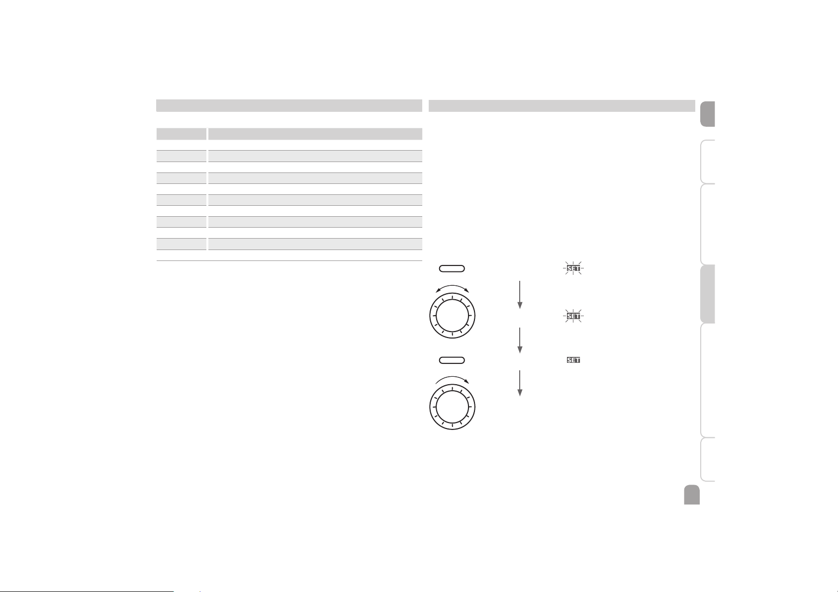
When the controller is commissioned or when it is reset, it will run a commissioning menu after the initialisation phase. The commissioning menu leads the user
through the most important adjustment channels needed for operating the system.
Commissioning menu
The commissioning menu consists of the channels described in the following. In
order to make an adjustment, press the right button (). starts flashing and
the adjustment can be made. Confirm the adjustment with the right button ().
Turn the Lightwheel
®
, the next channel will appear on the screen.
Adjustment mode flashing
Operation
Changing a value flashing
Confirming a value not flashing
to the next parameter
Page 16
en
16
Installation Indications, functions and options MessagesCommissioningOperation and function
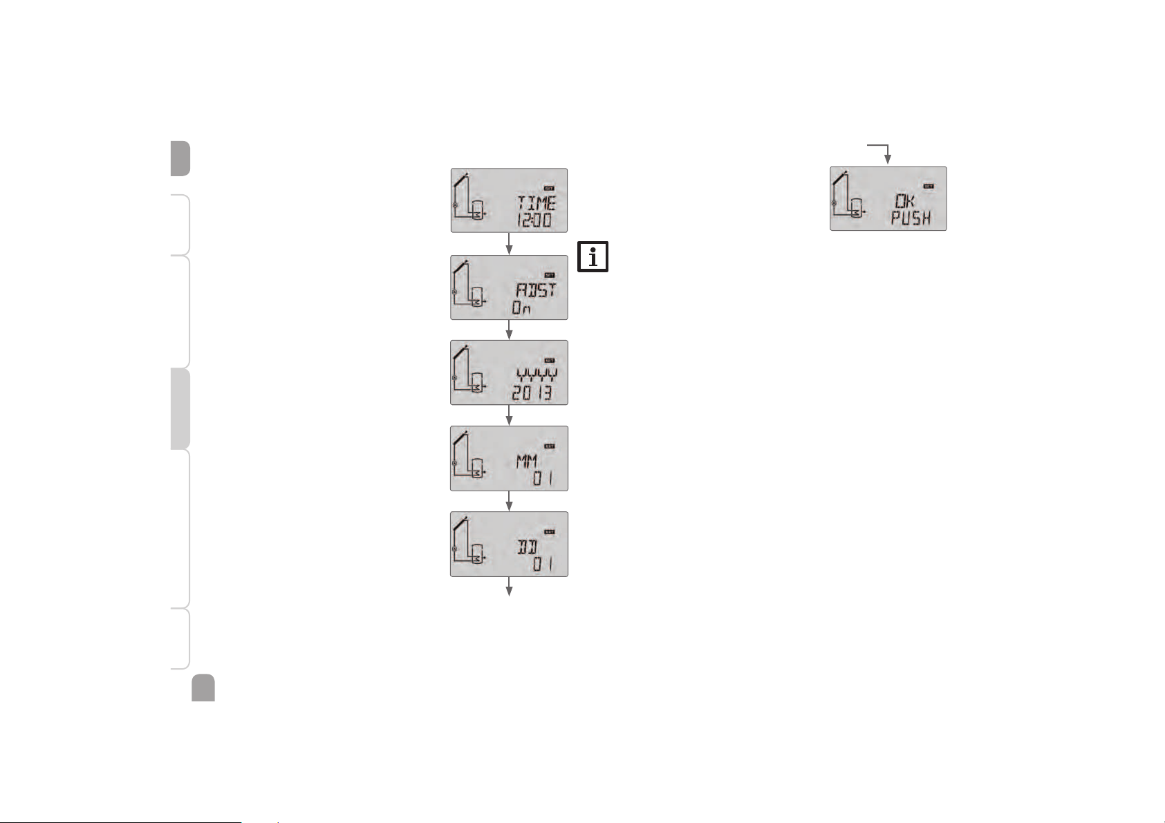
1. Time:
Î Adjust the clock time. First of all adjust the hours,
then the minutes.
2. Daylight savings time adjustment:
Î Activate or deactivate the automatic daylight sav-
ings time adjustment.
3. Date:
Î Adjust the date. First of all adjust the year, then the
month and then the day.
Î Complete the commissioning menu by
pressing the right button ().
The controller is then ready for operation and normally the factory settings will give close to optimum
operation.
Note
The adjustments carried out during commissioning can be changed anytime in the corresponding adjustment channel. Additional
functions and options can also be activated or
deactivated (see page 17).
Commissioning
Page 17
en
17
InstallationIndications, functions and optionsMessages Commissioning Operation and function
8 Indications, functions and options
Note
The values and adjustment channels as well as the adjustment ranges depend on the system selected, the functions and options as well as the
system components connected to the controller.
An additional document including a list with all options and parameters
can be downloaded at www.resol.com.
8.1 Status level
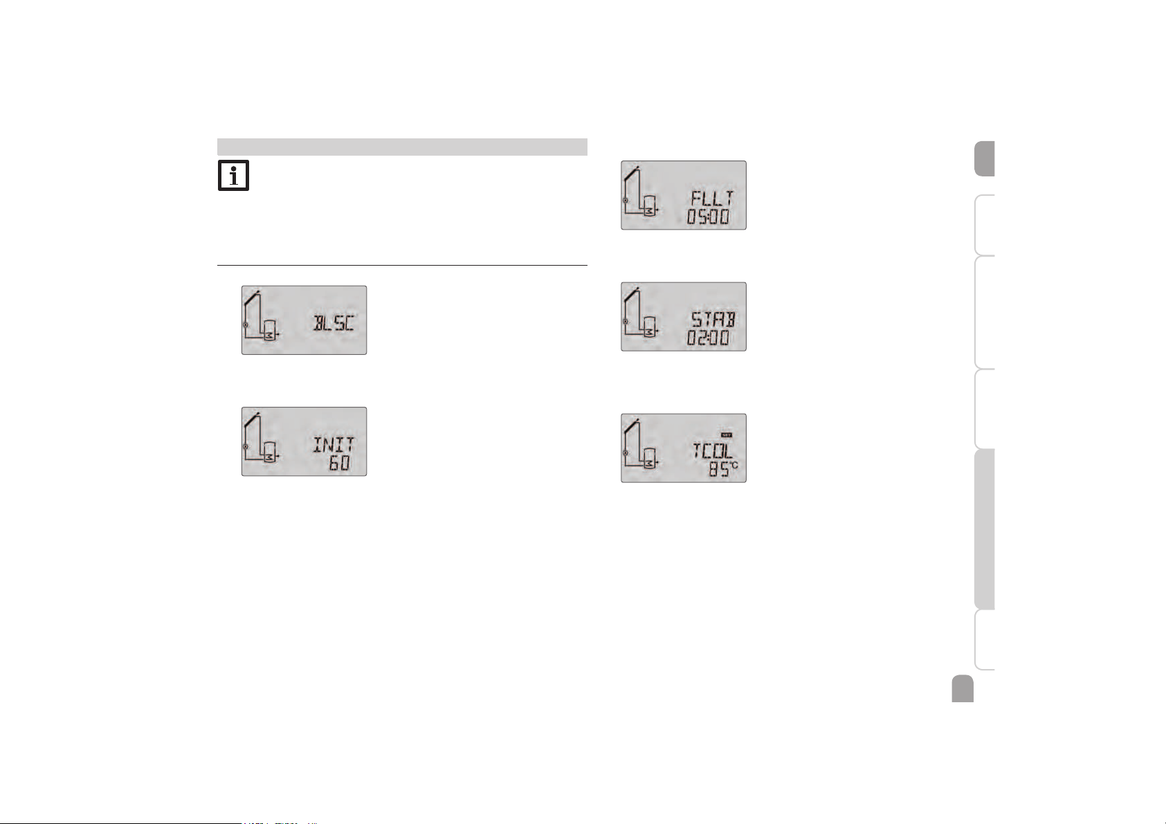
Display of blocking protection time
BLSC(2, 3)
Blocking protection active
Display of drainback time periods
INIT
Initialisation active
Indicates the time adjusted in tDTO, running backwards.
FLLT
Filling time active
Indicates the time adjusted in tFLL, running backwards.
STAB
Stabilisation
Indicates the time adjusted in tSTB, running backwards.
Display of collector temperatures
TCOL
Collector temperature
Display range: -40 … +260 °C
Displays the current collector temperature.
Page 18
en
18
Installation Indications, functions and options MessagesCommissioningOperation and function
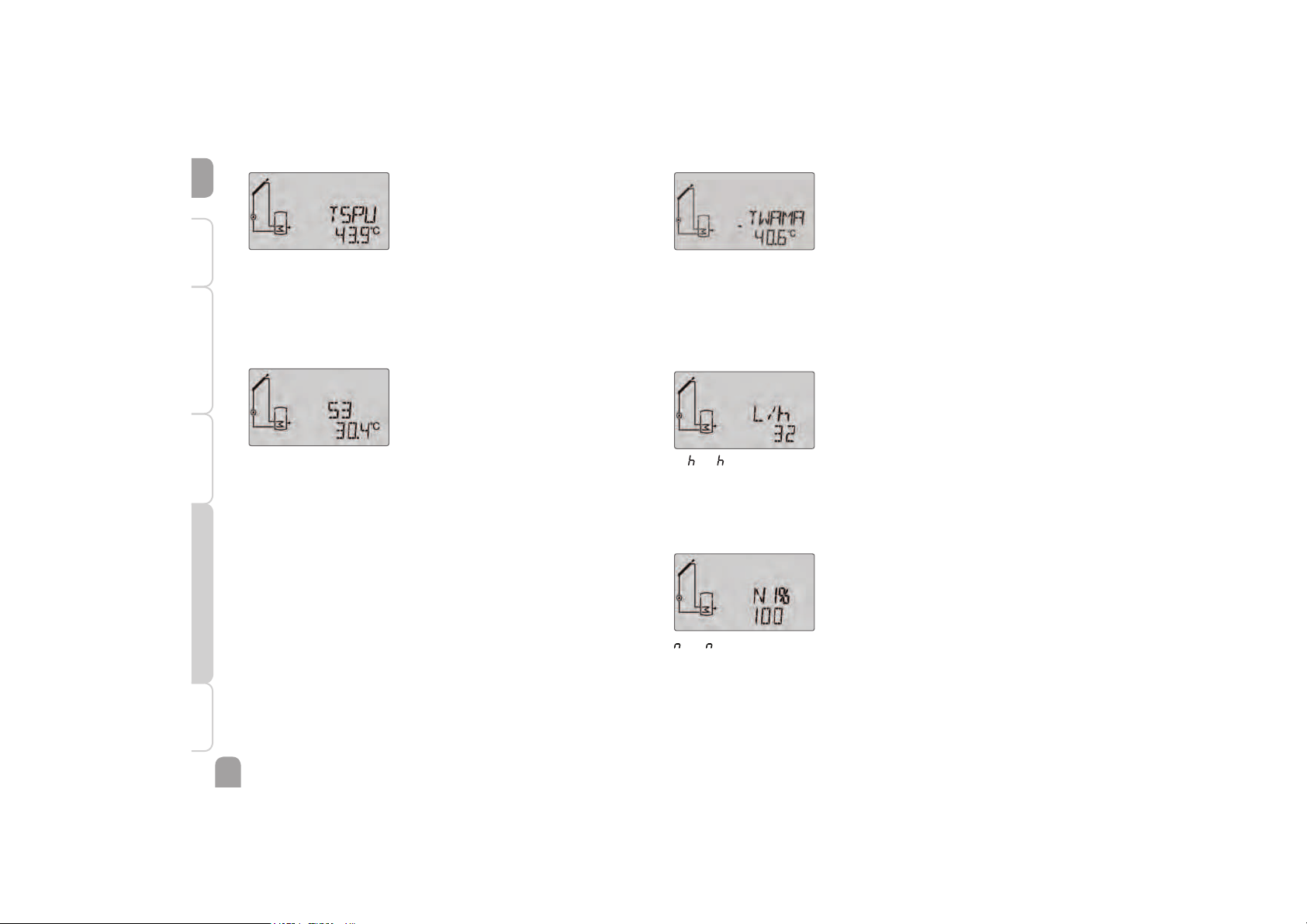
Display of store temperatures
TSTB, etc.
Store temperatures
Display range: -40 … +260 °C
Displays the current store temperature.
• TSTB : Store temperature base
• TSTT : Store temperature top
Display of temperatures at S3
S3
Sensor temperatures
Display range: -40 … +260 °C
Indicates the current temperature at the corresponding additional sensor
(without control function).
• S3 : Temperature sensor 3
Display of other temperatures
TWAMA, etc.
Other measured temperatures
Display range: -40 … +260 °C
Indicates the current temperature at the washing machine inlet. The display of
this temperature depends on the system selected.
• Temperature, washing machine, inlet
Display of fl ow rate
L/ , G/
Flow rate
Display range: 0 … 9999 l/h
Indicates the currently measured fl ow rate. This value is used for calculating
the heat quantity supplied (V40).
Display of speed
1 %, 2 %
Current pump speed
Display range: 20 … 100 % (standard pump / HE pump)
Indicates the current speed of the corresponding pump.
Page 19
en
19
InstallationIndications, functions and optionsMessages Commissioning Operation and function
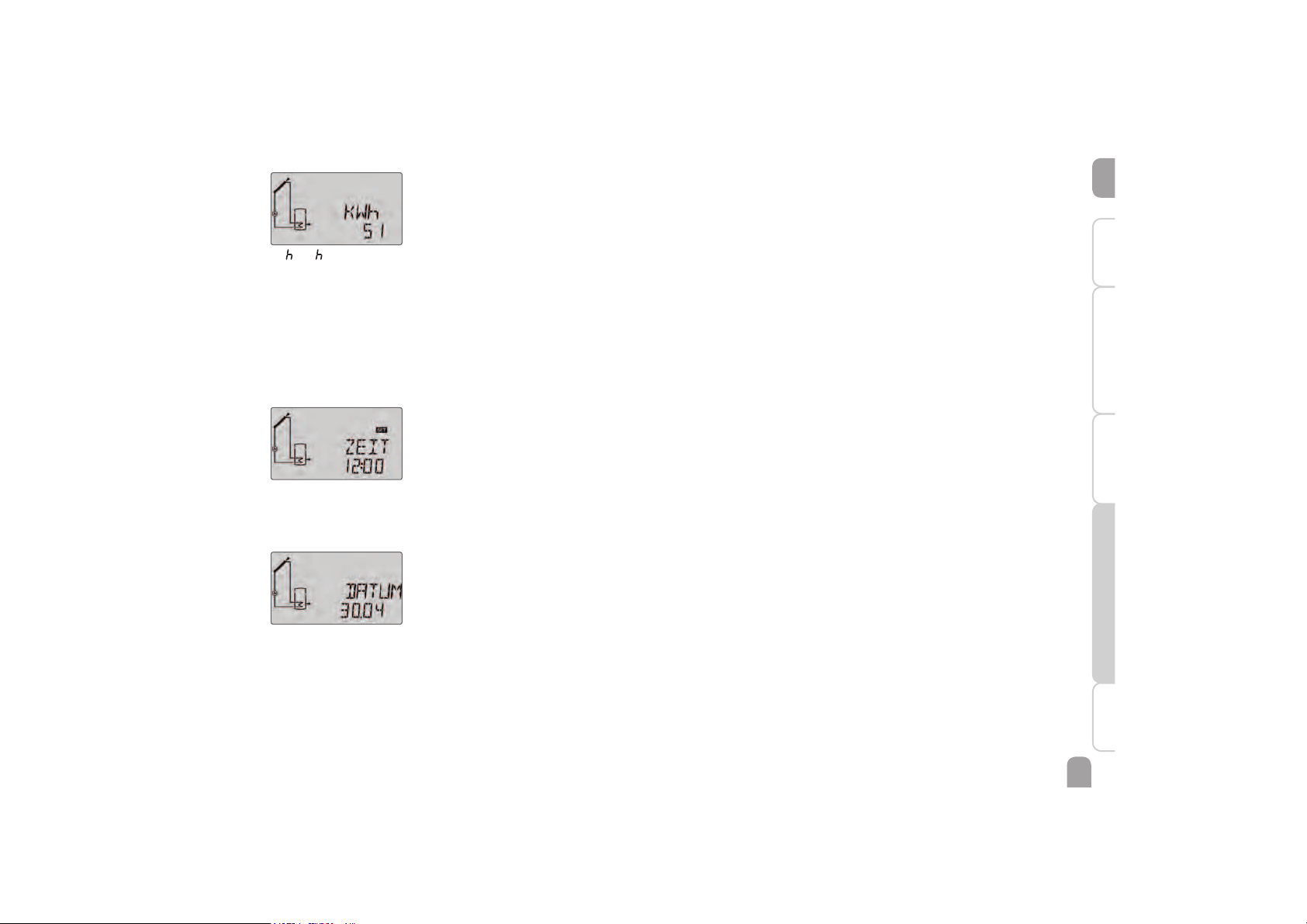
Display of heat quantity
kW /MW
Heat quantity in kWh / MWh
Indicates the heat quantity produced in the system. For this purpose, the heat
quantity measurement option has to be enabled. The fl ow rate as well as the
values of the reference sensors fl ow and return are used for calculating the
heat quantity supplied. It is shown in kWh in the kWh channel and in MWh
in the MWh channel. The overall heat quantity results from the sum of both
values.
The accumulated heat quantity can be set back to zero (see page 12).
Display of time
Time
Time
Indicates the current clock time.
Display of date
DATE
Date
Indicates the current date.
Page 20
en
20
Installation Indications, functions and options MessagesCommissioningOperation and function
8.2 Menu overview
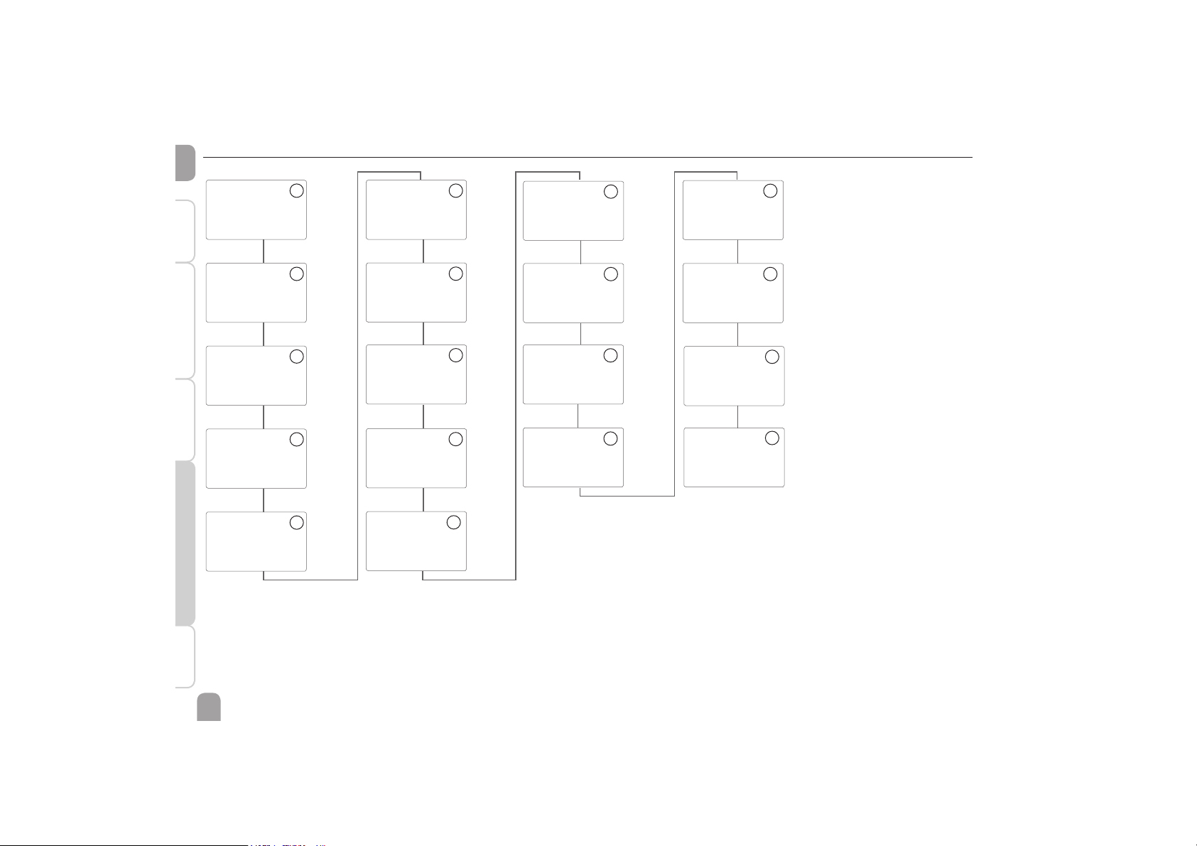
BALAN 1
BALANCE VALUES
WAMA 6
REL 9
RELAY
ADJUSTMENT
OHQM 13
HEAT QUANTITY
MEASUREMENT
BLPR 12
BLOCKING
PROTECTION
SYS 2
SYSTEM SELECTION
COOL 7
COOLING
FUNCTIONS
H-DAY 10
HOLIDAY
FUNCTION
SENS 14
SENSORS
COL 4
COLLECTOR
AH 8
AFTERHEATING
DATE 15
DATE
LOAD 3
LOADING STORE
MAN 11
MANUAL MODE
VDI 17
FUNCTION
CONTROL VDI 2169
RESET 18
FACTORY SETTING
ODB 5
DRAINBACK
LANG 16
LANGUAGE
» 21 » 26
» 28
» 31
» 22
» 27
» 29
» 32
» 22
» 30
» 34
» 30
» 35
» 23
» 27
» 33
» 25
» 33
Page 21
en
21
InstallationIndications, functions and optionsMessages Commissioning Operation and function
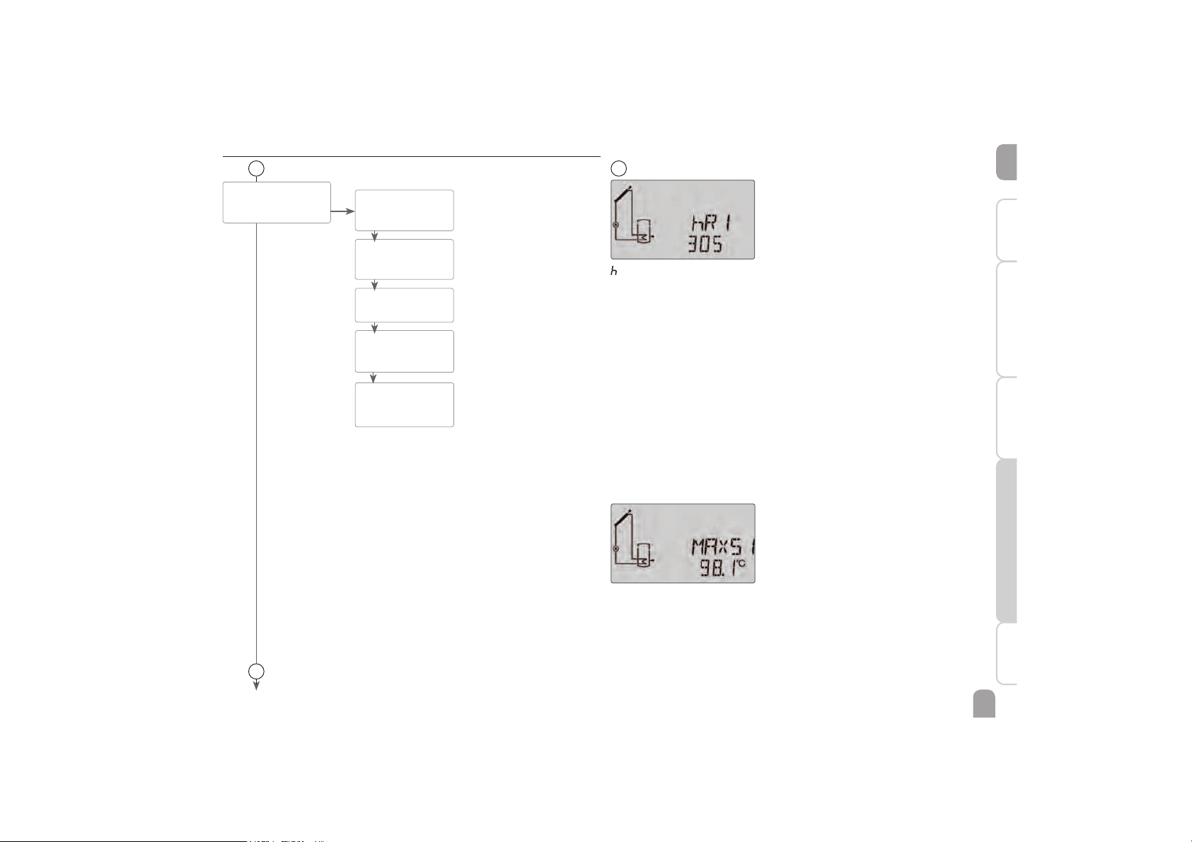
BALAN 1
PUSH
hR 1 (… 2)
Oper. hours
Relay 1 … 2
WAMA
Washing machine
cycles
DAYS
Operating days
MAXS1 (… 3)
Maximum temp.
Sensors 1 … 3
MINS1 (… 3)
Minimum temp.
Sensors 1 … 3
2
1
Operating hours counter
R (1, 2)
Operating hours counter
The operating hours counter accumulates the operating hours of the relay
(h R1 / h R2). Full hours are displayed.
The accumulated operating hours can be set back to zero (see page 12).
Washing machine cycles
WAMA
Indicates the number of washing machine cycles.
Operating days
DAYS
Display of operating days since commissioning or last reset. The operating days
cannot be set back to zero.
Minimum and maximum temperatures
MAXS1(2, 3)
Maximum temperatures at S1 … S3
MINS1(2, 3)
Minimum temperatures at S1 … S3
Indication of the minimum and maximum temperatures at S1…S3.
The temperature indication can be set back to zero (see page 12).
1
Balance values
OK
Page 22
en
22
Installation Indications, functions and options MessagesCommissioningOperation and function
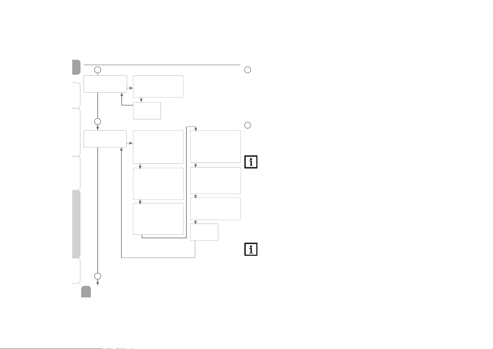
LOAD 3
PUSH
DTO
Switch-on temperature diff.
Adjustment range:
1.0 … 50.0 K
in steps of 0.5 K
Factory setting: 6.0 K
SMAXS
Sensor store maximum
temp.
Adjustment range:
S2, S3
Factory setting: S2
SMAX
Maximum store temperature
Adjustment range: 4 … 95 °C
in steps of 1 °C
Factory setting: 85 °C
HYST
Adjustment range: 0.1 … 10°
in steps of 0.1K
Factory setting 2K
DTF
Switch-off temperature diff.
Adjustment range:
0.5 … 49.5 K
in steps of 0.5 K
Factory setting: 4.0 K
DTS
Set temperature difference
Adjustment range:
1.5 … 50.0 K
in steps of 0.5 K
Factory setting: 10.0 K
2
System
Selecting the system
Each system has pre-programmed options and adjustments which can be activated
or changed respectively if necessary. Select the system first (see page 10).
3
'T control
The controller works as a standard differential controller. If the temperature reaches or exceeds the switch-on temperature difference, the pump switches on. When
the temperature difference reaches or falls below the adjusted switch-off temperature difference, the respective relay switches off.
Note
The switch-on temperature difference must be 0.5 K higher than the
switch-off temperature difference. The set temperature difference must be
at least 0.5 K higher than the switch-on temperature difference.
Speed control
If the temperature difference reaches or exceeds the switch-on temperature difference, the pump switches on at 100% speed for 10 s. Then, the speed is reduced to
the minimum pump speed value.
If the temperature difference reaches the adjusted nominal value, the pump speed
increases by one step (10 %). The response of the controller can be adapted via the
parameter Rise. Each time the difference increases by the adjustable rise value, the
pump speed increases by 10 % until the maximum pump speed of 100% is reached.
If the temperature difference decreases by the adjustable rise value, pump speed
will be decreased by one step.
Note
To enable speed control, the corresponding relay has to be set to AUTO,
MIN, MAX or ADAP (adjustment channel MAN) and relay control to
PULS, PSOL, PHEA or 0-10 V (adjustment channel REL).
SYS 2
PUSH
SYS
Basic system
Adjustment range: 1 … 3
Factory setting: 1
BACK
PUSH
BACK
PUSH
2
Adjustment level
4
3
Page 23
en
23
InstallationIndications, functions and optionsMessages Commissioning Operation and function
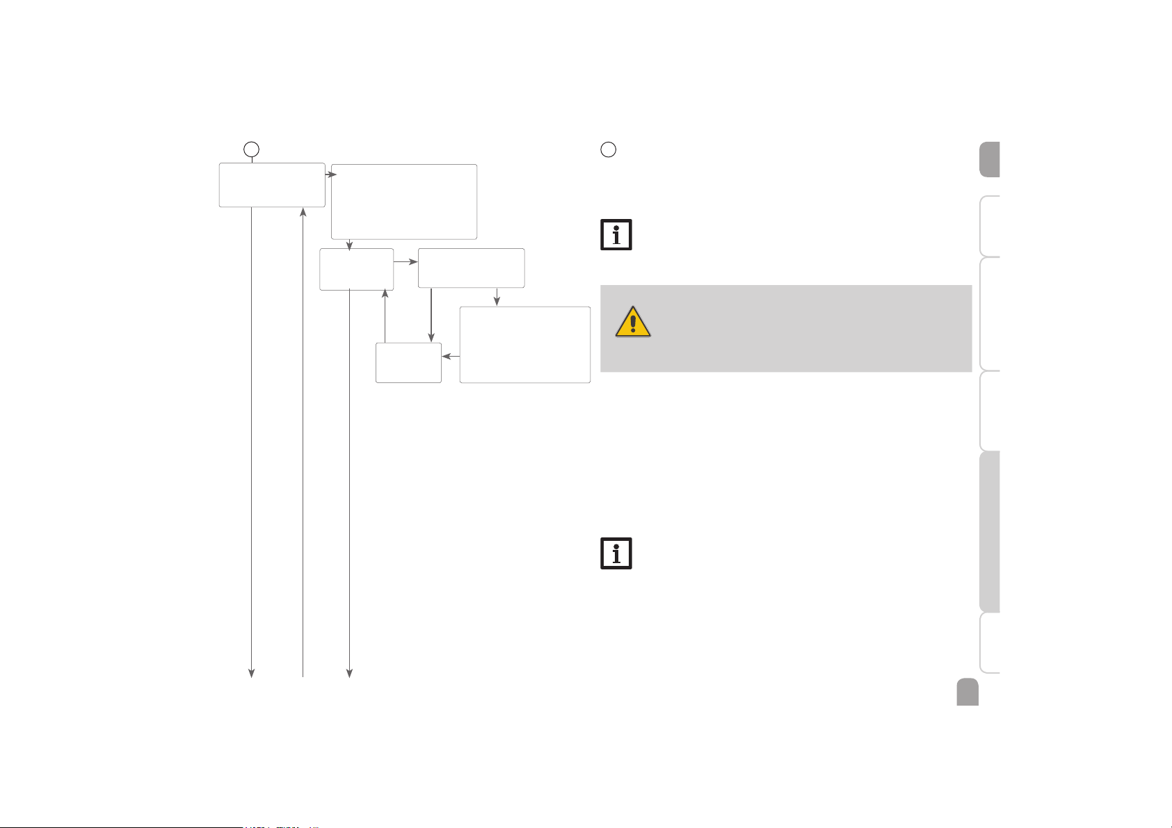
4
Collector emergency shutdown
When the collector temperature exceeds the adjusted collector emergency temperature, the solar pump (R1 / R2) switches off in order to protect the system
components against overheating (collector emergency shutdown). If the maximum
collector temperature is exceeded, is displayed (flashing).
Note
If the drainback option is activated, the adjustment range of the collector
emergency temperature is changed to 80 … 95 °C. Factory setting will be
95 °C.
WARNING!
Risk of injury! Risk of system damage by pressure surge!
If water is used as the heat transfer fluid in pressureless systems,
water will boil at 100 °C.
Î In pressureless systems with water as the heat trans-
fer fluid, do not set the collector limit temperature
higher than 95 °C.
Collector cooling
The collector cooling function keeps the collector temperature within the operating range by heating the store. If the store temperature reaches 95 °C the function
will switch off for safety reasons.
When the store temperature exceeds the adjusted maximum store temperature,
the solar system switches off. If the collector temperature increases to the adjusted
maximum collector temperature, the solar pump is activated until the collector
temperature falls below the maximum collector temperature. The store temperature may then exceed the maximum temperature, but only up to 95°C (emergency
shutdown of the store).
If the collector cooling is active, is displayed (flashing).
Note
This function is only available if the system cooling function and the heat
dump function are not activated.
CMAX
Collector maximum temp.
Adjustment range: 70 … 160 °C
in steps of 1 °C
Factory setting: 105 °C
Switch-on hysteresis: -5K
OCCO
Selection: OFF / ON
Factory setting: ON
OK
OFF ON
OCCO
PUSH
COL 4
PUSH
CEM
Collector emergency temperature
Adjustment range: 80 … 200 °C
in steps of 1 °C
Factory setting: 140 °C
Switch-on hysteresis: -10 K
a c
BACK
PUSH
4
b
Page 24
en
24
Installation Indications, functions and options MessagesCommissioningOperation and function
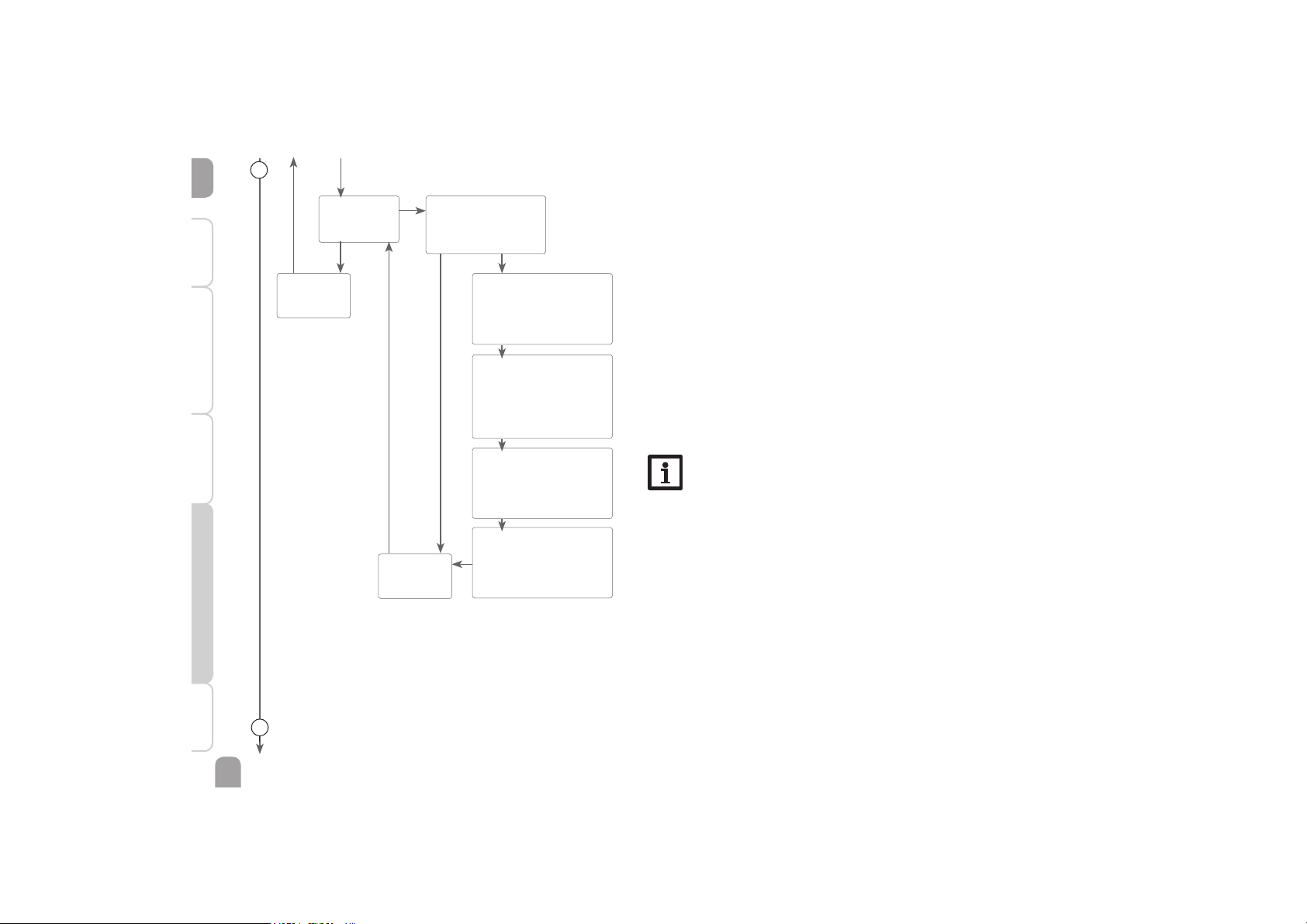
Tube collector function
This function is used for improving the switch-on behaviour in systems with
non-ideal sensor positions (e. g. with some tube collectors).
This function operates within an adjusted time frame. It activates the collector
circuit pump for an adjustable runtime between adjustable pauses in order to compensate for the delayed temperature measurement.
If the runtime is set to more than 10 s, the pump will be run at 100 % for the first
10 s of the runtime. For the remaining runtime, the pump will be run at the adjusted
minimum speed.
If the collector sensor is defective or the collector is blocked, this function is suppressed or switched off.
2-collector systems
In 2-collector systems, the tube collector function is available for each individual
collector field.
In 2-collector systems, the tube collector function will affect the inactive collector
field only. The solar pump of the active collector field will remain switched on until
the switch-off conditions are fulfilled.
Note
If the drainback option is activated, the tube collector function will not
be available.
OTCO (2)
Tube collector function
Selection: ON / OFF
Factory setting: OFF
TCST (2)
Starting time
Adjustment range:
00:00 … 23:00
Factory setting: 07:00
TCRU (2)
Runtime
Adjustment range: 30 … 600 s
in steps of 5 s
Factory setting: 30 s
TCEN (2)
Ending time
Adjustment range:
00:30 … 23:30
in steps of 00:30
Factory setting: 19:00
TCIN (2)
Standstill intervall
Adjustment range: 5 … 60 min
in steps of 00:01
Factory setting: 30 min
OTCO
PUSH
OK
OFF
ON
ca
BACK
PUSH
BACK
PUSH
4
b
5
Page 25
en
25
InstallationIndications, functions and optionsMessages Commissioning Operation and function
BACK
PUSH
5
5
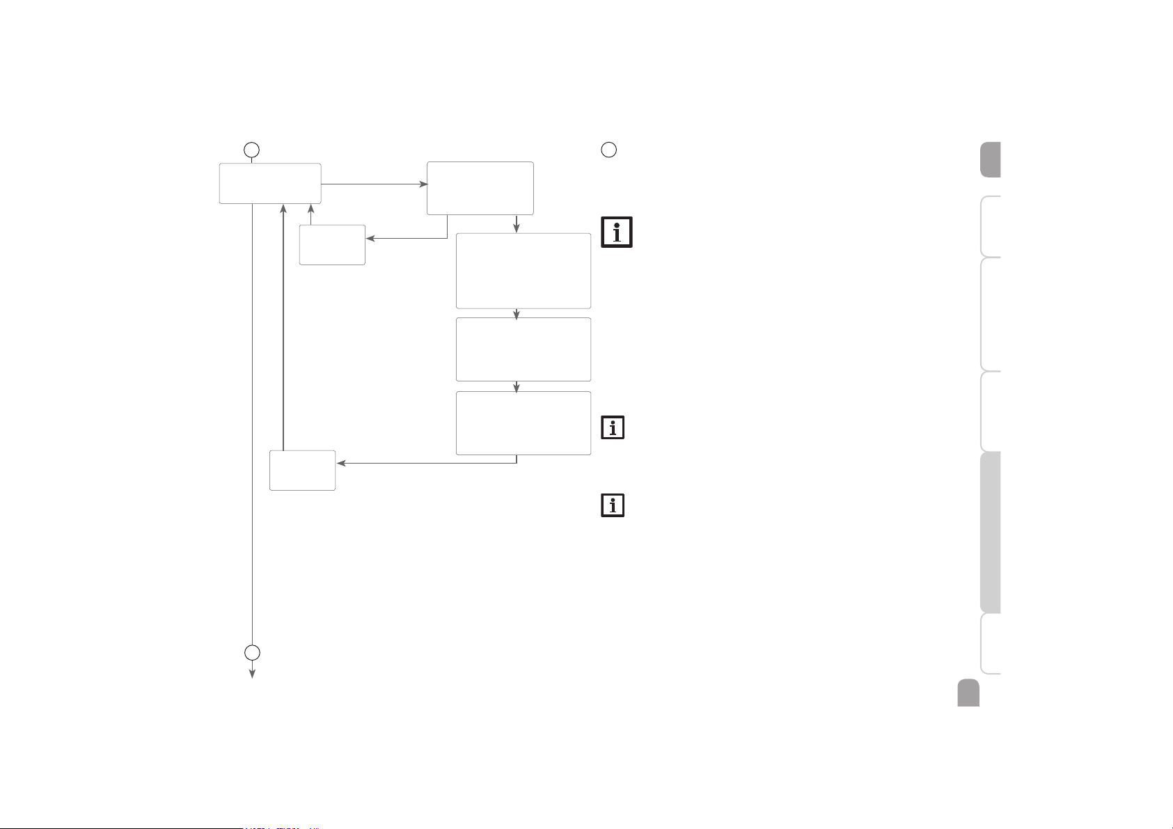
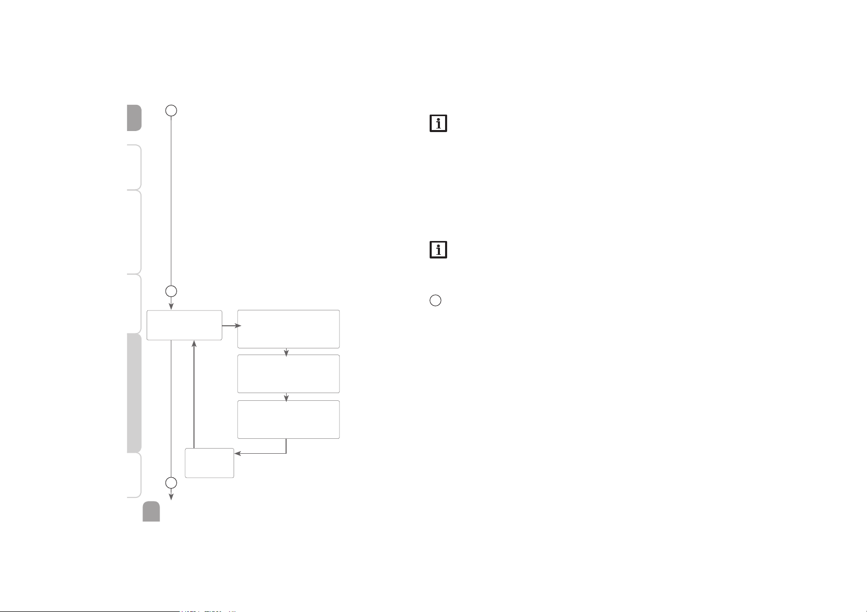
Drainback option
In a drainback system the heat transfer fluid will flow into a holding tank if solar
loading does not take place. The drainback option initiates the filling process if solar
loading is about to start. If the drainback option is activated, the following adjustment can be made:
Note
A drainback system requires additional components such as a holding tank.
The drainback option should only be activated if all components required
are properly installed.
Time period – switch-on condition
The parameter tDTO is used for adjusting the time period during which the
switch-on condition DT O must be permanently fulfilled.
Filling time
The filling time can be adjusted using the parameter tFLL. During this period, the
pump runs at 100 % speed.
Stabilisation
The parameter tSTB is used for adjusting the time period during which the switch-
off condition will be ignored after the filling time has ended.
Note
If the drainback option is activated, the cooling function and the antifreeze
function will not be available.
The H-DAY menu (holiday function) will also not be available and cannot be
selected by means of the microbutton .
Note
The drainback option is only available, if the cooling function is deactivated.
tDTO
Time period – switch-on
condition
Adjustment range: 1 … 100 s
in steps of 1 s
Factory setting: 60 s
tSTB / Stabilisation
Adjustment range:
1.0 … 15.0 min
in steps of 0.5 min
Factory setting: 2.0 min
tFLL / Filling time
Adjustment range:
1.0 … 30.0 min
in steps of 0.5 min
Factory setting: 5.0 min
5
BACK
PUSH
ODB
Drainback option
Selection: OFF / ON
Factory setting: OFF
ODB 5
PUSH
OK
ON
Page 26
en
26
Installation Indications, functions and options MessagesCommissioningOperation and function
BACK
PUSH
WAMA 6
PUSH
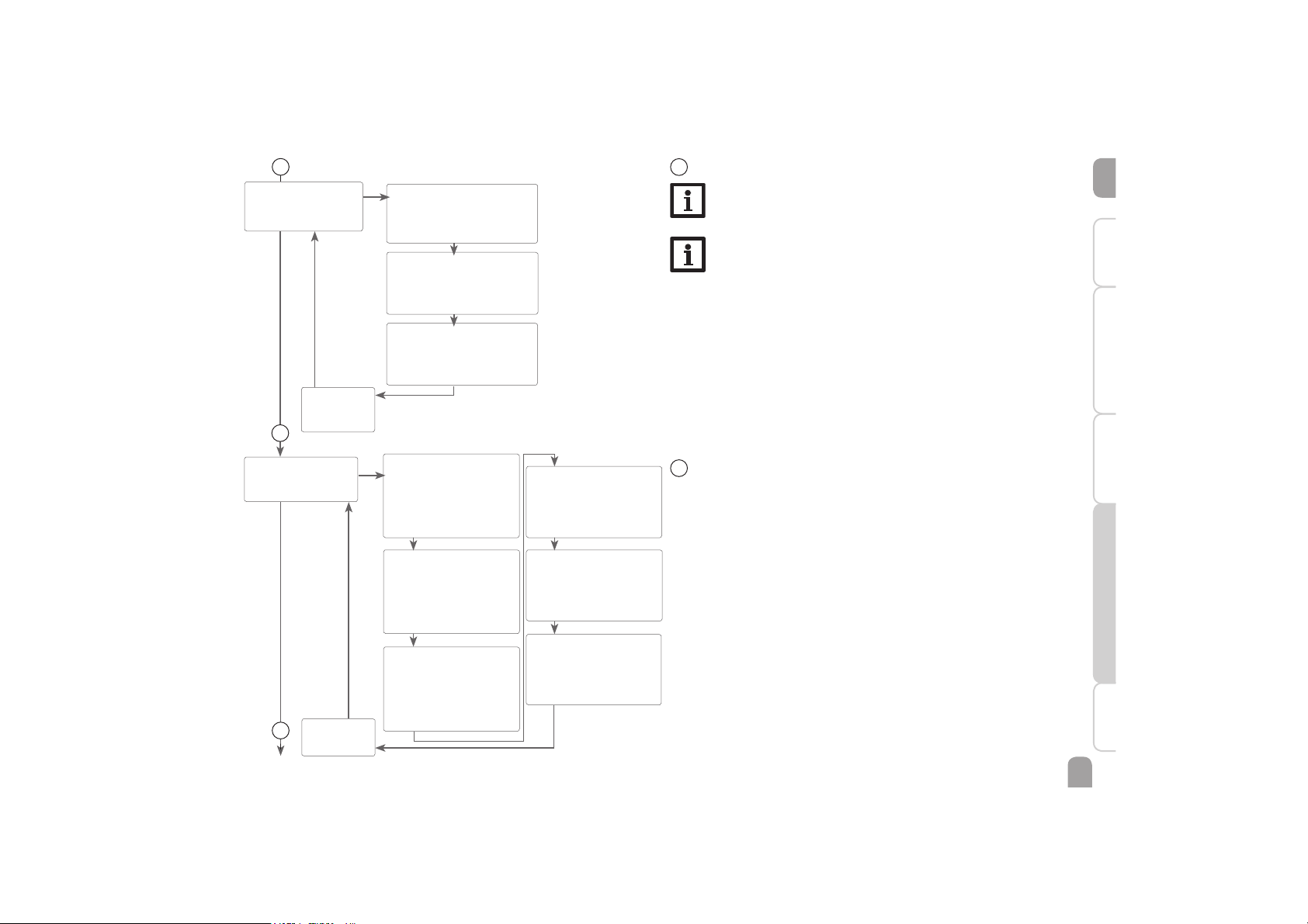
TWAMA
Switch-on temperature
Adjustment range: 20 … 90 °C
Factory setting: 40 °C
TIMER
Timer
Adjustment range: 01:00 … 60:00
Factory setting: 45:00
HYST
Switch-on hysteresis
Adjustment range: 0.0 … 10 K
Factory setting: 1 K
6
Washing machine water preheating
Preheating of the washing machine inlet (R2) can be carried out with a thermostat
function.
If the value at S4 reaches the switch-on temperature for the washing machine function, the function will be switched on and the temperature will be maintained at the
desired value for the adjusted time by means of the valve. After the adjusted time
has elapsed, the relay will be deactivated for the same duration.
7
Note
If the drainback function ODB is activated, the factory settings of the parameters DT O, DT F und DT S will be adapted to values suiting drainback
systems:
DT O = 10 K
DT F = 4 K
DT S = 15 K
Additionally, the adjustment range and the factory setting of the collector
emergency shutdown CEM will change:
Adjustment range: 80 … 120°C; Factory setting: 95 °C
Adjustments previously made in these channels will be overridden and have
to be entered again if the drainback option is deactivated later on.
Note
If the holiday function is activated, the drainback option will not be available.
6
5
Page 27
en
27
InstallationIndications, functions and optionsMessages Commissioning Operation and function
BACK
PUSH
7
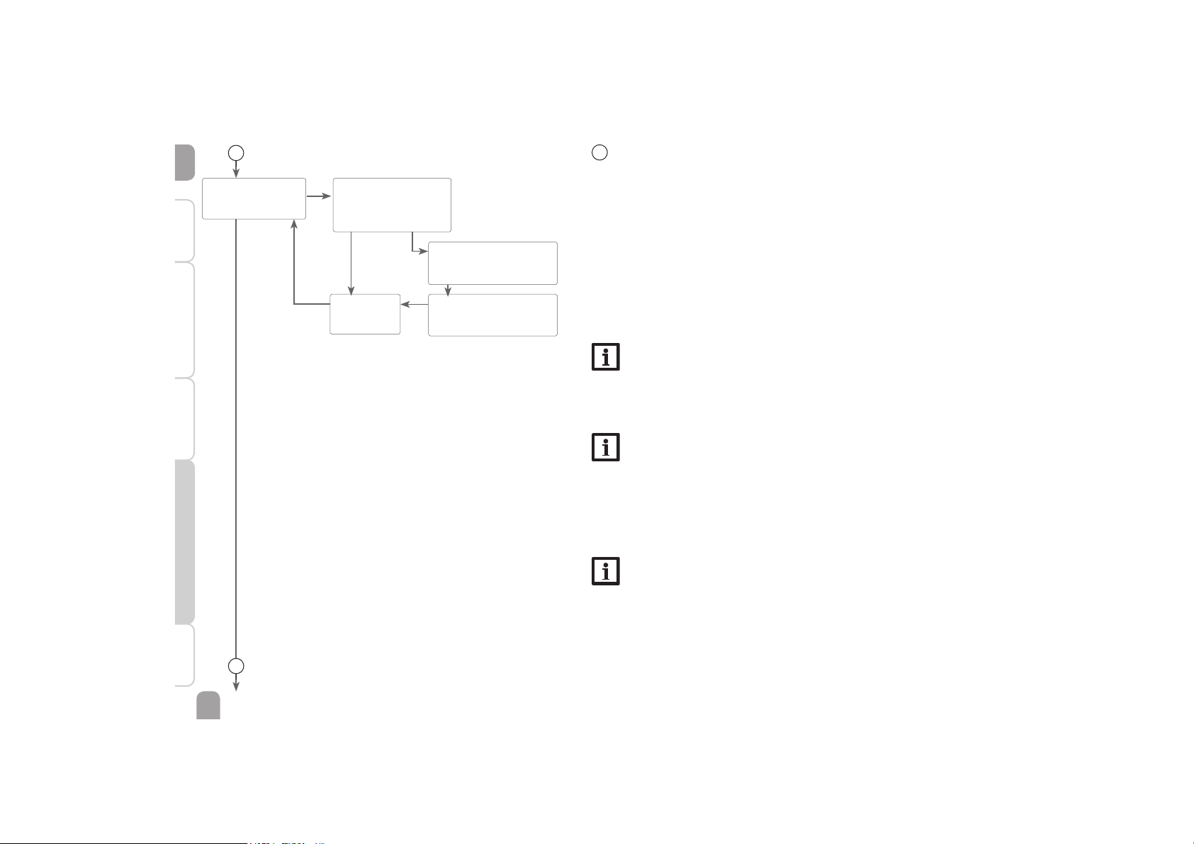
Cooling function
Note
If the temperature at the store sensor reaches 95 °C, the cooling function
will be blocked. The switch-on hysteresis is -5 K.
Note
If the cooling function is activated, the drainback option will not be available.
Store cooling
When the store cooling function is activated, the controller aims to cool down the
store during the night in order to prepare it for solar loading on the following day.
If the adjusted maximum store temperature is exceeded and the collector temperature falls below the store temperature, the system will be reactivated in order to
cool down the store.
DTCO and DTCF are used as the reference temperature differences.
DTCO
Switch-on temperature diff.
Adjustment range: 1.0 … 30.0 K
Factory setting: 20.0 K
DTCF
Switch-off temperature diff.
Adjustment range: 0.5 … 29.5 K
Factory setting: 15.0 K
OSTC
Store cooling option
Adjustment range: OFF / ON
Factory setting: OFF
OK
COOL 7
PUSH
8
7
BACK
PUSH
AH 8
PUSH
AH O
Thermostat switch-on temp.
Adjustment range:
0.5 … 95.0 °C
in steps of 0.5 °C
Factory setting: 55.0 °C
AH F
Thermostat switch-off temp.
Adjustment range:
0.5 … 94.5 °C
in steps of 0.5 °C
Factory setting: 60.0 °C
t1O
Switch-on time 1
Adjustment range:
00:00 … 23:45
Factory setting: 00:00
in steps of 15 min
t2 (3) O
Switch-on time 2 (3)
Adjustment range:
00:00 … 23:45
Factory setting: 00:00
t1F
Switch-off time 1
Adjustment range:
00:00 … 23:45
Factory setting: 00:00
t2 (3) F
Switch-off time 2 (3)
Adjustment range:
00:00 … 23:45
Factory setting: 00:00
OK
9
8
Afterheating / Thermostat function
The thermostat function works independently from the solar operation and can
e. g. be used for using surplus energy or for afterheating.
• AH O < AH F
thermostat function for afterheating
• AH O > AH F
thermostat function for using surplus energy
In order to block the thermostat function for a certain period, there are 3 time
frames t1 … t3. The switch-on and switch-off times can be adjusted in steps of
15 min. If the switch-on and the switch-off times are identical, the time frame is
inactive.
If the thermostat function is supposed to run from 06:00 a.m. and 09:00 a.m. only,
adjust t1 O to 06:00 a.m. and t1 F to 09:00 a.m.
If all time frames are set to 00:00, the thermostat function is solely temperature
dependent.
Page 28
en
28
Installation Indications, functions and options MessagesCommissioningOperation and function
10
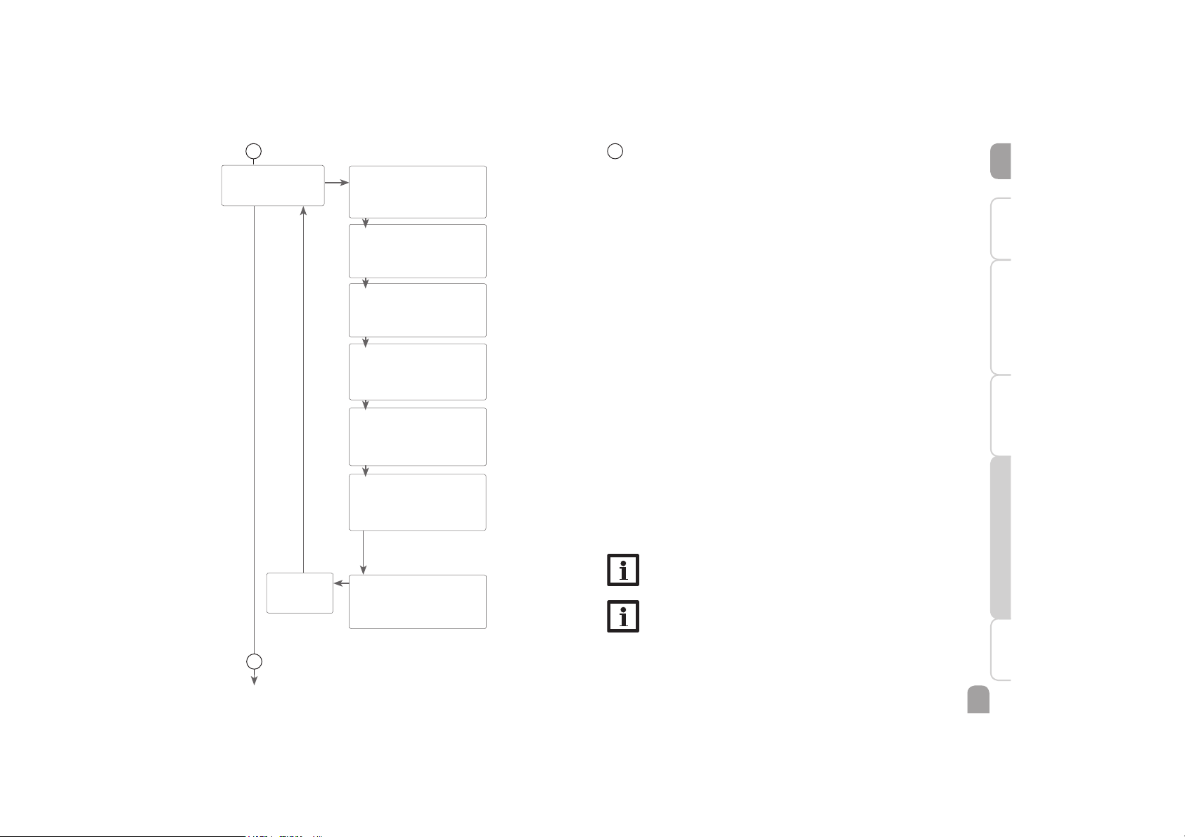
REL / Relay control
Selection: ONOF, Puls,
PSOL, PHEA, 0 - 10, ADAP
Factory setting: PSOL
REL 9
PUSH
MAX / Maximum speed
Adjustment range: 20 … 100 %
Factory setting: 100 %
MIN / Minimum speed
Adjustment range: 15 … 100 %
Factory setting: 30 %
9
Relay control
With this parameter, the relay control type can be adjusted. The following types
can be selected:
Adjustment for standard pump without speed control
• ONOF : Pump on / pump off
Adjustment for standard pump with speed control
• PULS : Burst control via semiconductor relay
Adjustment for high-efficiency pump (HE pump)
• PSOL : PWM profile solar pump
• PHEA : PWM profile heating pump
• 0-10 : Speed control via a 0 - 10 V signal
• ADAP : Speed control signal via a VBus
®
/ PWM interface adapter
Note
For more information about connecting HE pumps see page 10.
Minimum speed
In the adjustment channel MIN a relative minimum speed for a pump connected
can be allocated to the output R1.
Note
When loads which are not speed-controlled (e. g. valves) are used, the
pump speed value of the corresponding relay must be set to 100 % or the
control type must be set to ONOF in order to deactivate pump speed
control.
Maximum speed
In the adjustment channel MAX a relative maximum speed for a pump connected
can be allocated to the output R1.
Note
When loads which are not speed-controlled (e. g. valves) are used, the
pump speed value of the corresponding relay must be set to 100 % or the
control type must be set to ONOF in order to deactivate pump speed
control.
9
OK
ONOF Puls, PSOL,
PHEA,
0 - 10, ADAP
BACK
PUSH
Page 29
en
29
InstallationIndications, functions and optionsMessages Commissioning Operation and function
10
Holiday function
The holiday function is used for operating the system when no water consumption
is expected, e. g. during a holiday absence. This function cools down the system in
order to reduce the thermal load.
Only if the holiday function has been activated with the parameter DAYS will the
adjustments described in the following become active.
2 cooling functions are available: Collector cooling and store cooling
The collector cooling function keeps the collector temperature within the operating range by heating the store. If the store temperature reaches 95 °C the function
will switch off for safety reasons.
When the store temperature exceeds the adjusted maximum store temperature,
the solar system switches off. If the collector temperature increases to the adjusted
maximum collector temperature, the solar pump is activated until the collector
temperature falls below the maximum collector temperature. The store temperature may then exceed the maximum temperature, but only up to 95°C (emergency
shutdown of the store).
If the collector cooling is active, is displayed (flashing).
The store cooling option is activated by default and can be deactivated with the
parameter OSTC. Store cooling starts when the store temperature exceeds the
collector temperature by the adjustable value DTCO. It switches off if the store
temperature reaches THOL or if the temperature difference falls below DTCF.
The parameter THOL is used for adjusting the temperature for store cooling.
The parameter DAYS can be used for entering the number of days for a holiday
absence. If the parameter is set to a value higher than 0, the function becomes
active using the adjustments that have previously been made in the H-DAY menu.
The days will be counted backwards at 00:00. If the value is set to 0, the function
is deactivated.
Note
The parameter DAYS can be accessed via the microbutton only (see
page 29).
Note
The adjustments described in this chapter are independent of those in the
COOL menu, which are inactive during a holiday.
H-DAY 10
PUSH
10
DTCO
Switch-on temperature diff.
Adjustment range: 1.0 … 30.0 K
Factory setting: 20.0 K
DTCF
Switch-off temperature diff.
Adjustment range: 0.5 … 29.5 K
Factory setting: 15.0 K
THOL
Temp. store cooling holiday
Adjustment range: 4 … 95 °C
Factory setting: 45 °C
OSTC
Store cooling option
Adjustment range: OFF / ON
Factory setting: ON
CMAX
Collector maximum temp.
Adjustment range: 70 … 130 °C
Factory setting: 105 °C
OCCO
Collector cooling option
Adjustment range: OFF / ON
Factory setting: OFF
OK
AHOFF
Afterheating Holiday
Selection: ON / OFF
Factory setting: OFF
system with
DHW heating
BACK
PUSH
10
Page 30
en
30
Installation Indications, functions and options MessagesCommissioningOperation and function
BACK
PUSH
BACK
PUSH
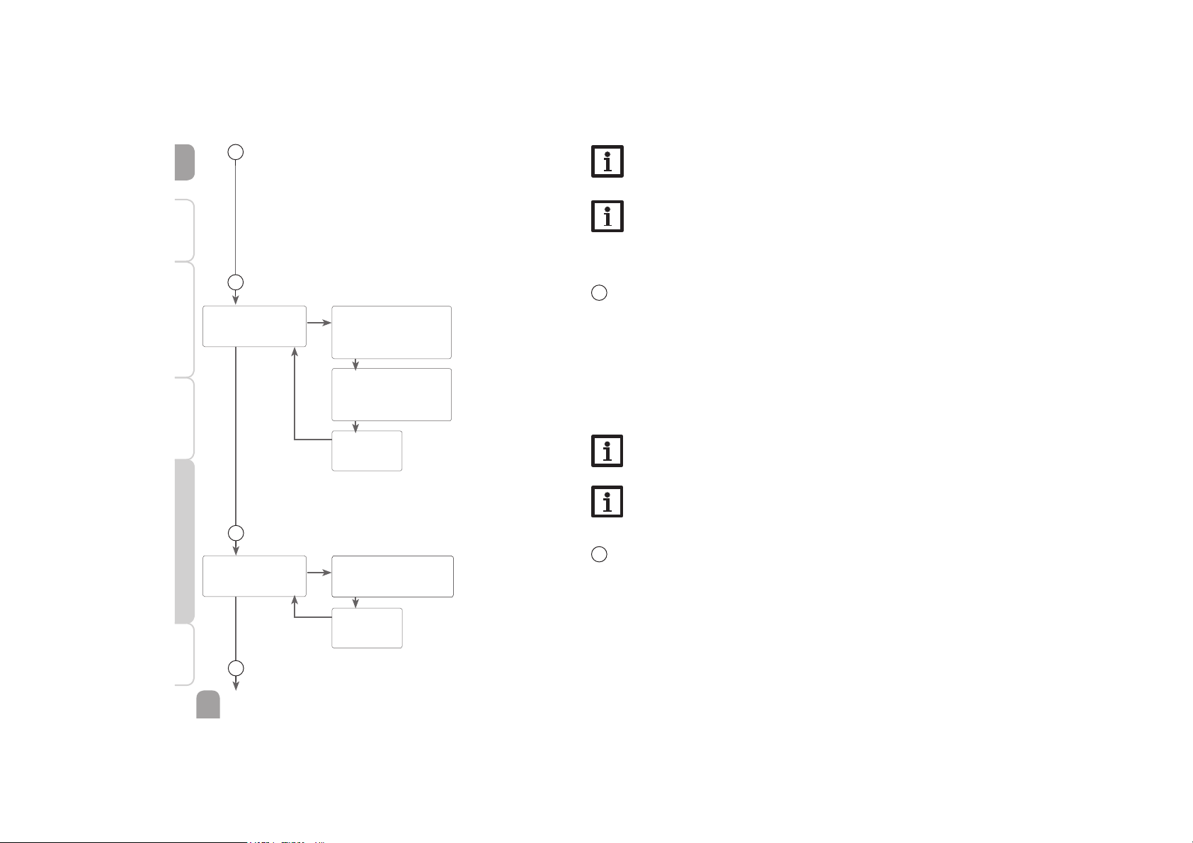
11
Manual mode
For control and service work, the operating mode of the relays can be manually
adjusted. For this purpose, select the adjustment channel MAN1(2) (for R1, 2) in
which the following adjustments can be made:
Operating mode
AUTO : relay in automatic mode
OFF : relay is switched off
MIN : relay is switched with adjusted minimum speed (not if REL = ONOF)
MAX : relay is switched with adjusted maximum speed
Note
After service and maintenance work, set the relay mode back to AUTO.
Normal operation is not possible in manual mode.
Note
For information about the control LED in the Lightwheel® see page 10.
MAN 11
PUSH
BLPR 12
PUSH
MAN1
Adjustment range: AUTO,
ON, OFF, MIN, MAX
Factory setting: AUTO
BLPR
Adjustment range: ON, OFF
Factory setting: OFF
MAN2
Adjustment range:
AUTO, ON, OFF
Factory setting: AUTO
12
Blocking protection
In order to protect the pumps against blocking after standstill, the controller is
equipped with a blocking protection function. This function switches on the relays
one after another every day at 12:00 a.m. for 10 s at 100 %.
OK
OK
12
11
13
10
Note
When the drainback option is activated, the holiday function will not be
available and cannot be selected by means of the microbutton .
Note
If the holiday function is activated, the drainback option will not be available.
Page 31
en
31
InstallationIndications, functions and optionsMessages Commissioning Operation and function
13
OHQM 13
PUSH
FMAX
Flow rate in l/min
Adjustment range: 0.5 … 100.0
in steps of 0.1
Factory setting: 6.0
MEDT
Heat transfer fluid
Adjustment range: 0 … 3
Factory setting: 3
MED%
Antifreeze concentration in vol.
% (MED% will not be displayed
when MEDT 0 or 3 is used)
Adjustment range: 20 … 70 %
in steps of 1 %
Factory setting: 45 %
FTYPE
Heat quantity measurement type
Selection: 1, 2, 3
Factory setting: 1
OHQM
Heat quantity measurement option
Adjustment range: OFF / ON
Factory setting: OFF
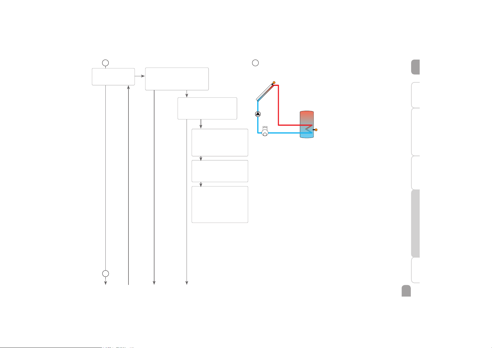
13
Heat quantity measurement
The heat quantity measurement can be carried out in 3 different ways: without V40
flowmeter, with V40 flowmeter or with Grundfos Direct Sensor
TM
.
Flow sensor
V40 /
Flowmeter
Return
sensor
Example of flow and return sensor positions for heat quantity measurement with a fixed flow
rate value (flowmeter) or a V40 flowmeter.
Î Enable the heat quantity measurement option in the channel OHQM.
Î Select the type of flow rate detection in the channel FTYPE.
Flow rate detection type:
1 : Fixed flow rate value
2 : V40 flowmeter
3 : Grundfos Direct Sensor
TM
Heat quantity measurement with fixed flow rate value
The heat quantity balancing (estimation) uses the difference between the flow and
return temperatures and the entered flow rate (at 100 % pump speed).
Î Adjust 1 in the channel FTYPE
Î Read the flow rate (l/min) and adjust it in the FMAX channel.
Î Adjust the antifreeze type and concentration of the heat transfer fluid in the
channels MEDT and MED%.
Antifreeze type:
0 : Water
1 : Propylene glycol
2 : Ethylene glycol
3 : Tyfocor
®
LS / G-LS
OK
OFF ON
13
FTYPE = 1
a b c
Page 32
en
32
Installation Indications, functions and options MessagesCommissioningOperation and function
13
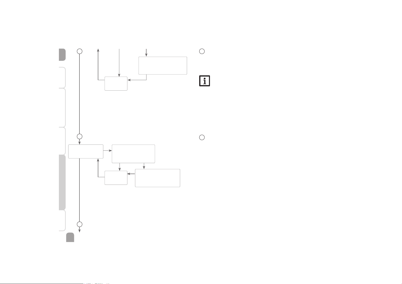
Heat quantity measurement with V40 flowmeter:
The heat quantity measurement uses the difference between the flow temperature
measured at S3 and the adjusted return temperature Tcold and the flow rate
transmitted by the flowmeter.
Î Adjust 2 in the channel FTYPE
Note
If the flow rate detection type V40 has been adjusted, the impulse rate of the
corresponding sensor must be adjusted in the SENS menu (see page 32).
Heat quantity measurement with Grundfos Direct SensorTM:
The heat quantity measurement uses the difference between the flow temperature
measured at the Grundfos Direct Sensor
TM
and the adjusted return temperature
Tcold and the flow rate transmitted by the Grundfos Direct SensorTM.
Î Adjust 3 in the channel FTYPE
SENS 14
PUSH
SEN 1 (…4) / Sensor type
Selection: Pt1000, KTY, Pt500
(S5: Pt1000, KTY, Pt500, V40)
Factory setting: Pt1000
VIMP / Impulse rate of the V40
Adjustment range: OFF,
0,5 … 100,0 l/imp
Factory setting: OFF
14
Sensors
The sensor type can be selected for the sensor inputs S1 to S4.
The impulse rate of the sensor connected can be adjusted for the sensor input V40.
OFF
OK
ON
BACK
PUSH
14
15
13
Tcold
Cold water temperature
Adjustment range: 0 … 20 °C
Factory setting: 10 °C
BACK
PUSH
a b c
Page 33
en
33
InstallationIndications, functions and optionsMessages Commissioning Operation and function
DATE 15
PUSH
TIME / Time
Adjustment range: 00:00 … 23:59
Factory setting: 12:00
ADST
Automatic daylight savings time
adjustment
Selection: ON / OFF
Factory setting: ON
MM / Month
Adjustment range: 01 … 12
Factory setting: 03
YYYY / Year
Adjustment range: 2010 … 2099
Factory setting: 2010
DD / Day
Adjustment range: 01 … 31
Factory setting: 15
15
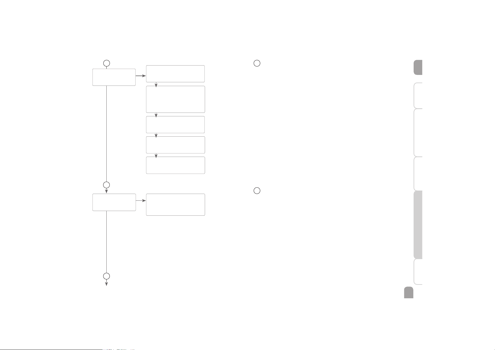
Time and date
The controller is equipped with a real time clock required e. g. for the thermostat
function.
In the display, the lower line indicates the day followed by the month.
15
16
Language
In this adjustment channel the menu language can be chosen.
• NL : Dutch
• EN : English
• DE : German
• FR : French
• ES : Spanish
• IT : Italian
LANG 16
PUSH
LANG
Language
Selection: NL, EN, DE, FR, ES, IT
Factory setting: NL
OK
OK
16
17
Page 34
en
34
Installation Indications, functions and options MessagesCommissioningOperation and function
17
VDI 17
PUSH
NIGHT
Night circulation monitoring option
Selection: ON
/ OFF
Factory setting: ON
FL / RE
FL / RE interchange monitoring option
Selection: ON / OFF
Factory setting: ON
'T HI
'T too high option
Selection: ON / OFF
Factory setting: ON
17
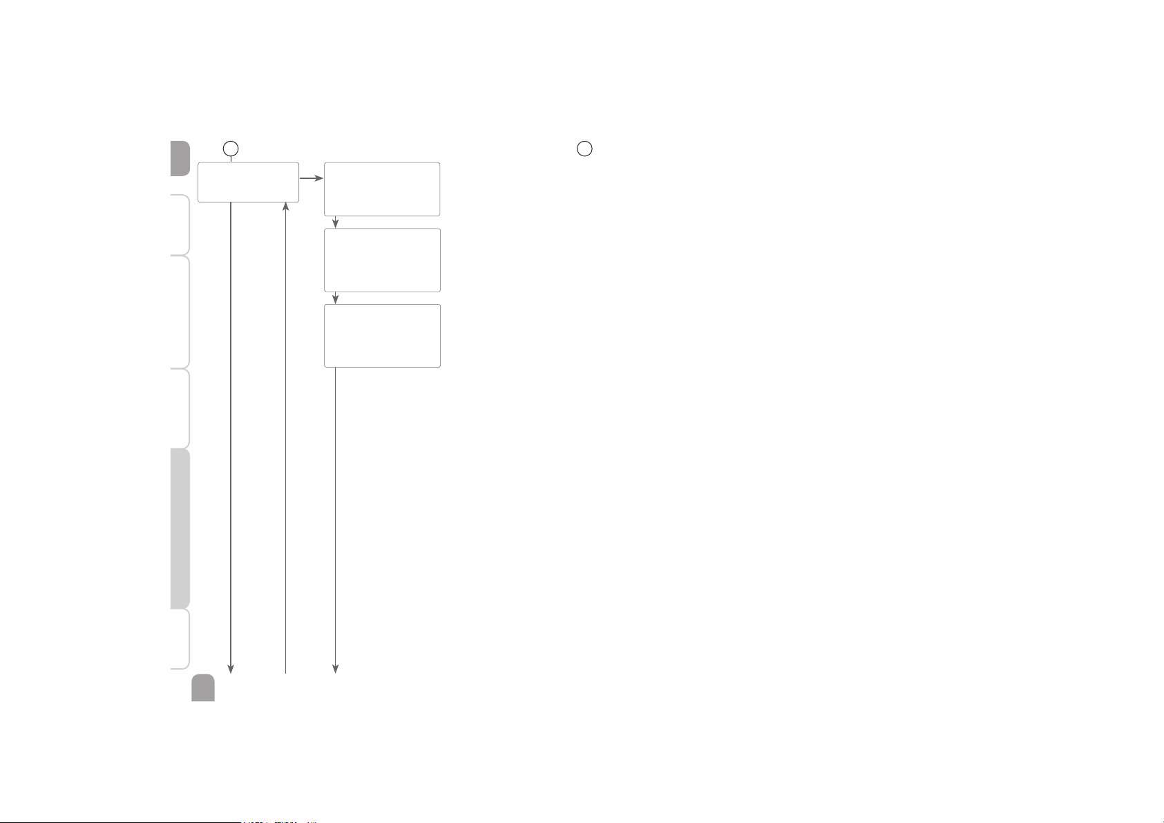
Function control
'T monitoring
This function is used for monitoring the temperature difference.. The message 'T
too high is shown, if solar loading has been carried out for a period of 20 min with a
differential higher than 50 K. Normal operation is not aborted or inhibited, but the
system should be checked for the cause of the warning.
Possible causes are:
• pump power too weak
• blocked system components
• circulation problems in the collector
• air inside the pipework
• defective valve/ defective pump
Night circulation
This function can be used for detecting thermal circulation inside the solar circuit
that leads to an unwanted cooling of the store. A warning message will appear when
the following condition has been detected for at least 1 min during the period between 11 p.m. and 5 a.m.:
• collector temperature exceeds 40 °C
The delay time of 1 min ensures that the message is not triggered by short-term
fault conditions.
Possible causes are:
• defective non-return valves
• defective valve
• wrongly adjusted time
Flow and return interchanged
This function is used for detecting an interchange of the flow and return pipe or a
badly placed collector sensor. For this purpose, the collector temperature is monitored for plausibility during the switch-on phases of the solar pump. An error message will appear, if the plausibility criteria have not been met 5 times in a row.
OK
a b
c
Page 35
en
35
InstallationIndications, functions and optionsMessages Commissioning Operation and function
ST1(2)
Maximum store temperature
monitoring store 1, 2
Selection: ON / OFF
Factory setting: ON
ST1(2)MX
Maximum store temperature
exceedance counter
STMAX
Maximum store temperature
monitoring option
Selection: ON / OFF
Factory setting: ON
STMAX
PUSH
17
Maximum store temperature
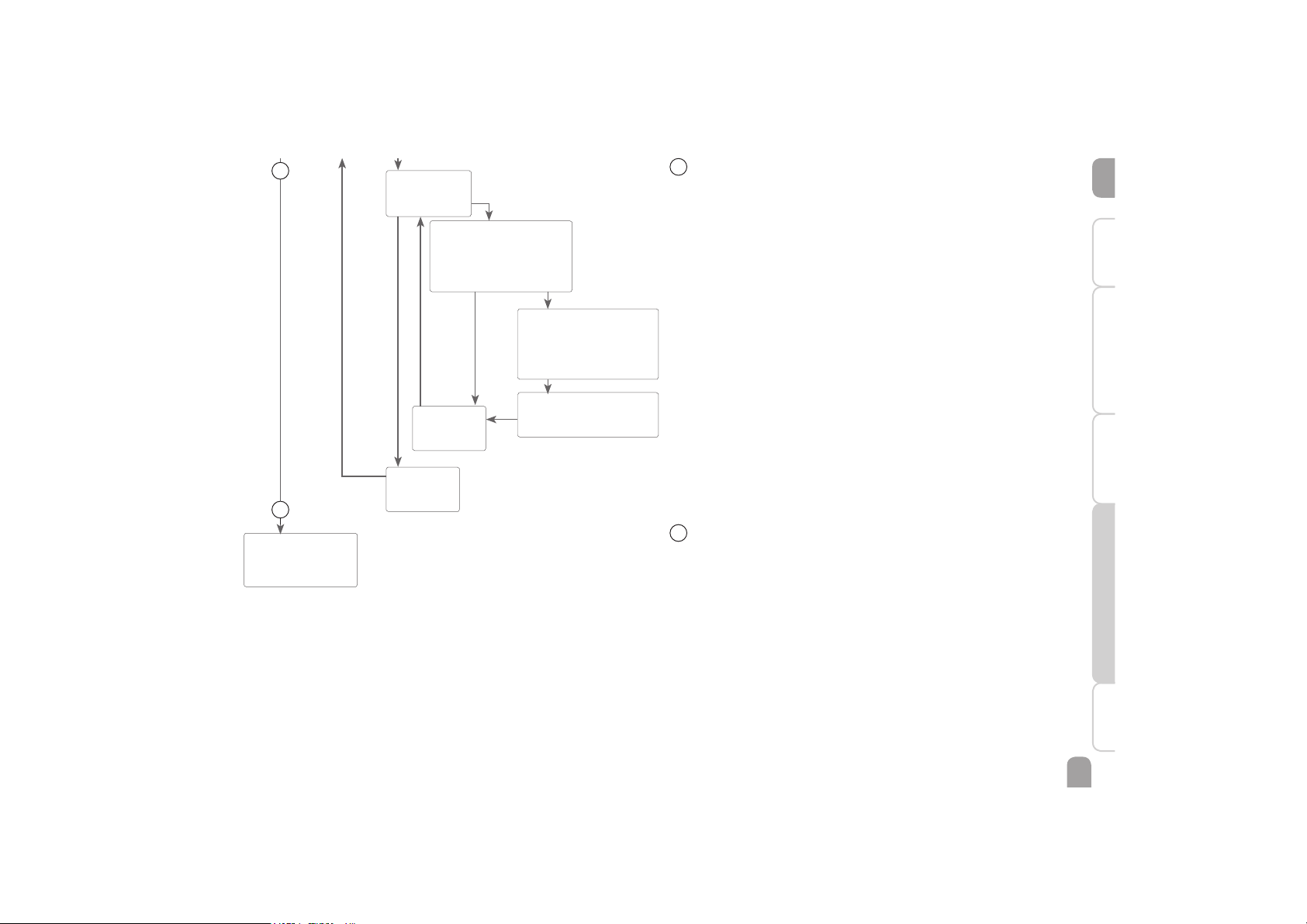
This function is used for detecting and indicating if the adjusted maximum store
temperature has been exceeded. The controller compares the current store temperature to the adjusted maximum store temperature, thus monitoring the store
loading circuits.
The maximum store temperature is considered exceeded when the temperature
measured at the store sensor exceeds the adjusted maximum store temperature by
at least 5 K. The monitoring becomes active again as soon as the store temperature
falls below the adjusted maximum store temperature.
The channels ST1, ST2 can be used for selecting the stores to be monitored. The
number of exceedances is displayed in the ST(2)MX channels. A possible cause for
an unwanted exceedance of the maximum store temperature is a defective valve.
OFF ON
OK
a b
c
BACK
PUSH
BACK
PUSH
18
Reset
By means of the reset function, all adjustments can be set back to the factory
settings.
18
RESET 18
PUSH
17
Page 36
en
36
Installation Indications, functions and options MessagesCommissioningOperation and function
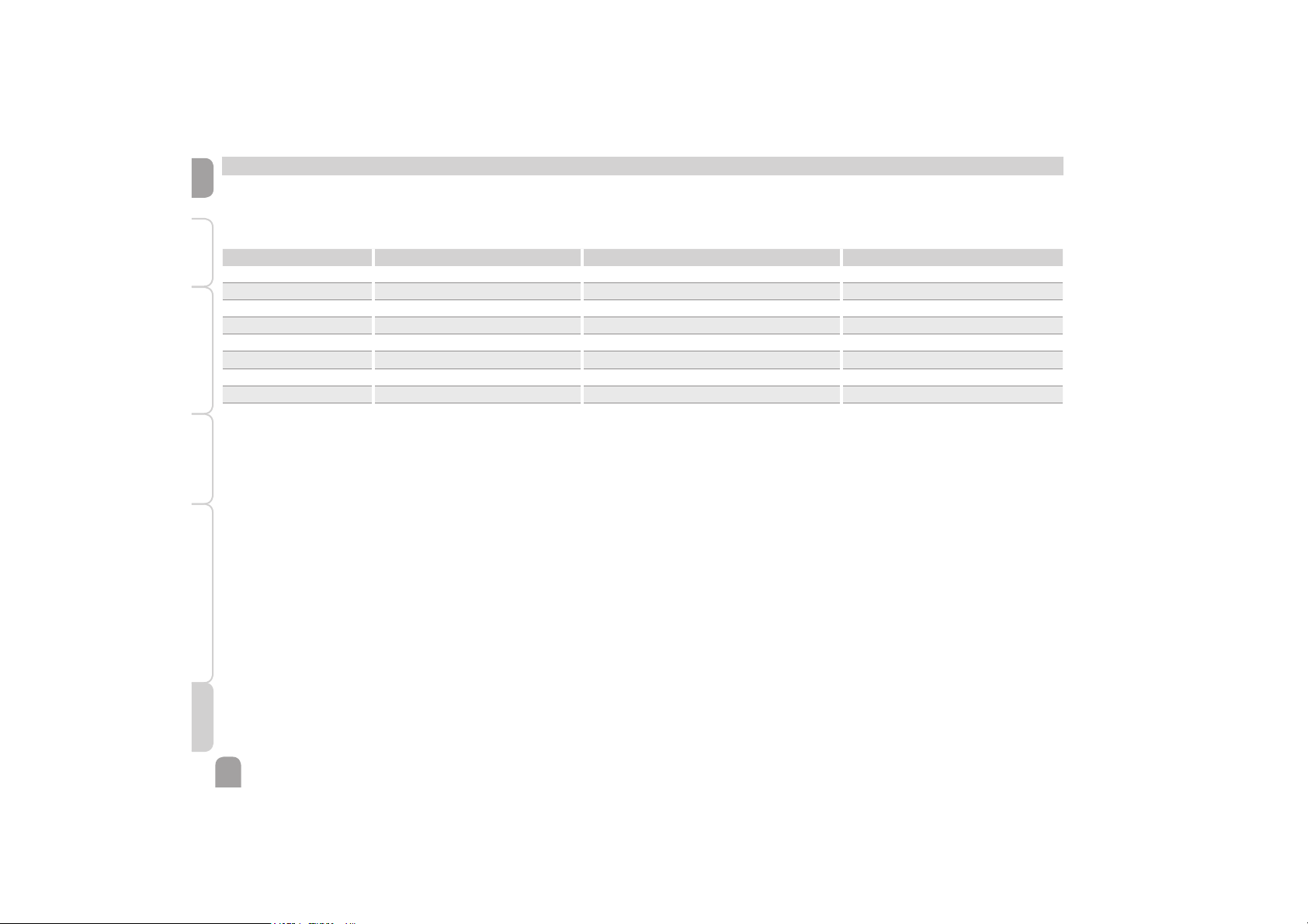
In the case of an error, the control LED starts flashing red and a message is indicated
in the status display. A warning triangle is additionally indicated. If more than one
error or fault condition has occurred, only the one with the highest priority will be
displayed as a message in the status display.
Error code display Plain text display Monitoring function Cause
0001 !LINE BREAK SENSOR X! Sensor line break Sensor line broken
0002 !SHORT CIRCUIT SENSOR X! Sensor short circuit Sensor line short-circuited
0011 !'T TOO HIGH! 'T too high Collector 50 K > than store to be loaded
0021 !NIGHT CIRCULATION! Night circulation Betw. 11 p.m. and 5 a.m. col. temp > 40 °C
0031 !FL/RE INTERCHANGED! FL/RL interchanged Col. temp. does not rise after switching on
0041 !FLOW RATE MONITORING! Flow rate monitoring No flow rate at sensor
0061 !DATA MEMORY DEFECTIVE! Storing and changing adjustments not possible
0081 STORE MAX EXCEEDED Maximum store temperature St. max has been exceeded
CODE 0000 0000 / 0262 User code
After the error has been removed and acknowledged, the error message disappears.
Î In order to acknowledge an error message, select the message and press the left button (
") for 2 s.
In the case of a sensor error, the system switches off, and a message appears on the
display. Additionally, a corresponding value for the error type assumed is indicated.
9 Messages
Page 37
en
37
InstallationIndications, functions and optionsMessages Commissioning Operation and function
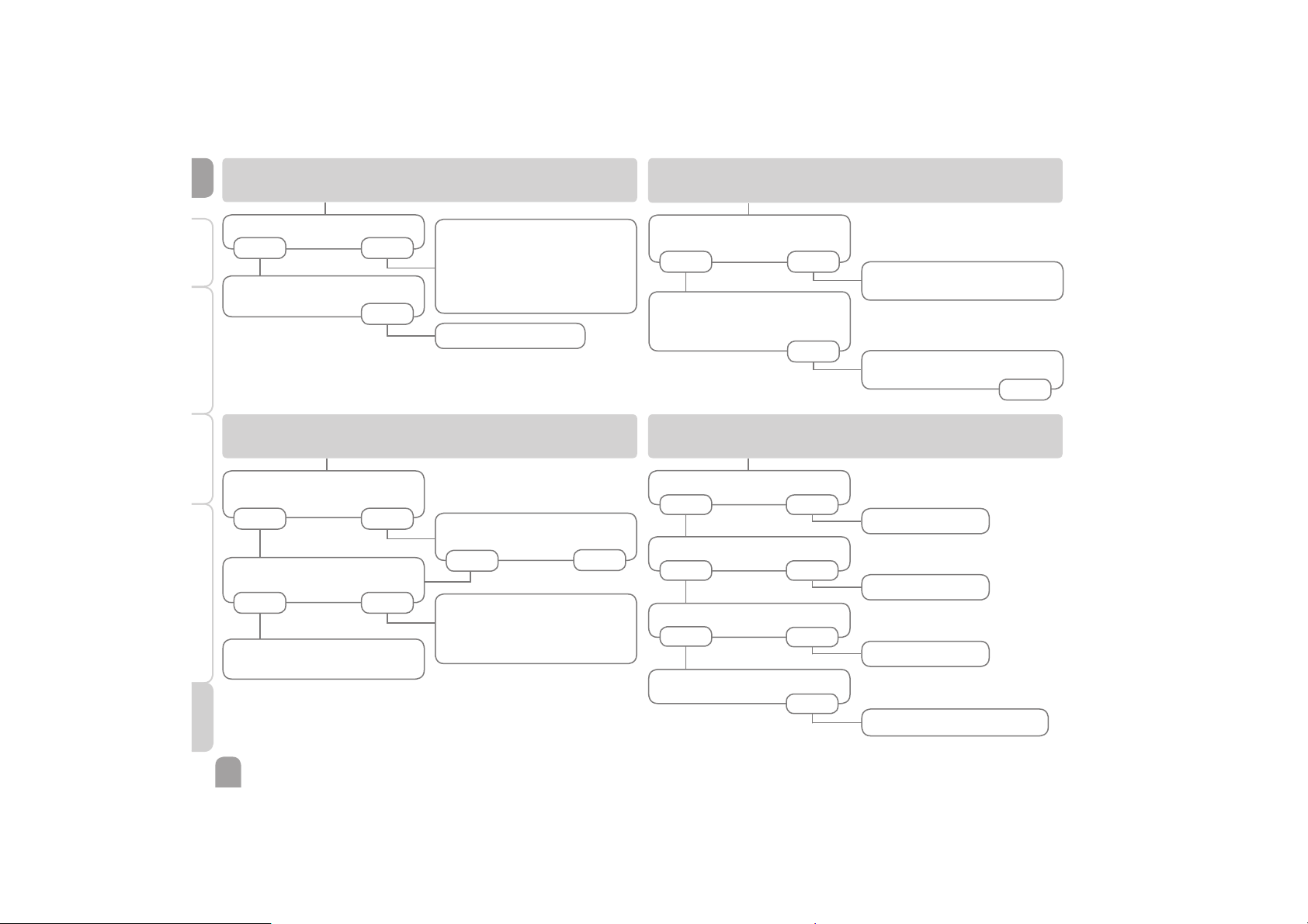
10 Troubleshooting
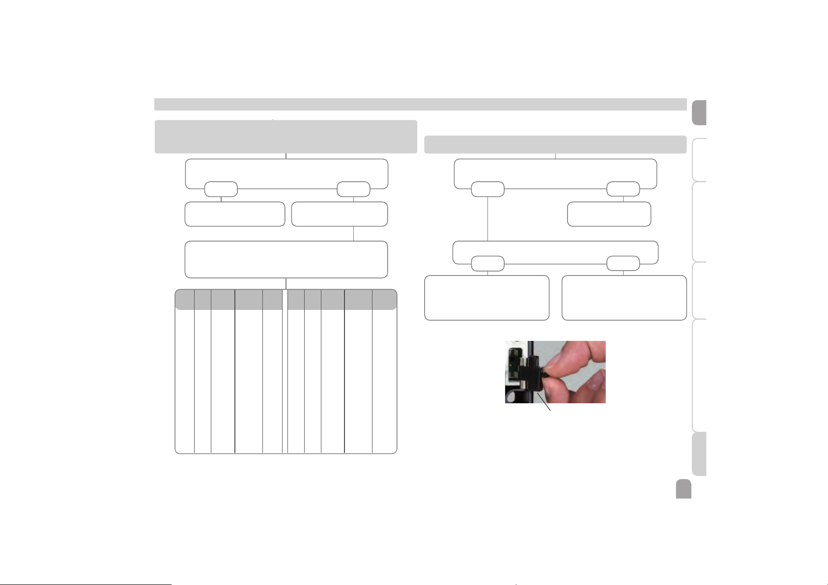
If a malfunction occurs, a message will appear on the display of the controller.
Fuse
Lightwheel® or display are permanently off.
Press the right button (). Display illuminated?
no yes
Controller has been in
standby, everything o.k.
Check the supply line and recon-
nect it.
The fuse of the controller could be
blown. The fuse becomes accessible
when the cover is removed.The fuse
can then be replaced.
Check the power supply of the controller. Is it disconnected?
no yes
Disconnected temperature sensors can be checked with an
ohmmeter. Please check if the resistance values correspond
with the table.
°C °F ȍ
Pt500ȍPt1000
ȍ
KTY
°C °F ȍ
Pt500ȍPt1000
ȍ
KTY
-10 14 481 961 1499 55 131 607 1213 2502
-5 23 490 980 1565 60 140 616 1232 2592
0 32 500 1000 1633 65 149 626 1252 2684
5 41 510 1019 1702 70 158 636 1271 2778
10 50 520 1039 1774 75 167 645 1290 2874
15 59 529 1058 1847 80 176 655 1309 2971
20 68 539 1078 1922 85 185 664 1328 3071
25 77 549 1097 2000 90 194 634 1347 3172
30 86 559 1117 2079 95 203 683 1366 3275
35 95 568 1136 2159 100 212 693 1385 3380
40 104 578 1155 2242 105 221 702 1404 3484
45 113 588 1175 2327 110 230 712 1423 3590
50 122 597 1194 2413 115 239 721 1442 3695
Control LED in the Lightwheel® is flashing red. The symbol is indicated on the
display and the symbol flashes.
Sensor fault. An error code instead of a temperature is shown
on the corresponding sensor display channel.
- 88.8888.8
Cable is broken.
Check the cable.
Short circuit.
Check the cable.
Page 38
en
38
Installation Indications, functions and options MessagesCommissioningOperation and function
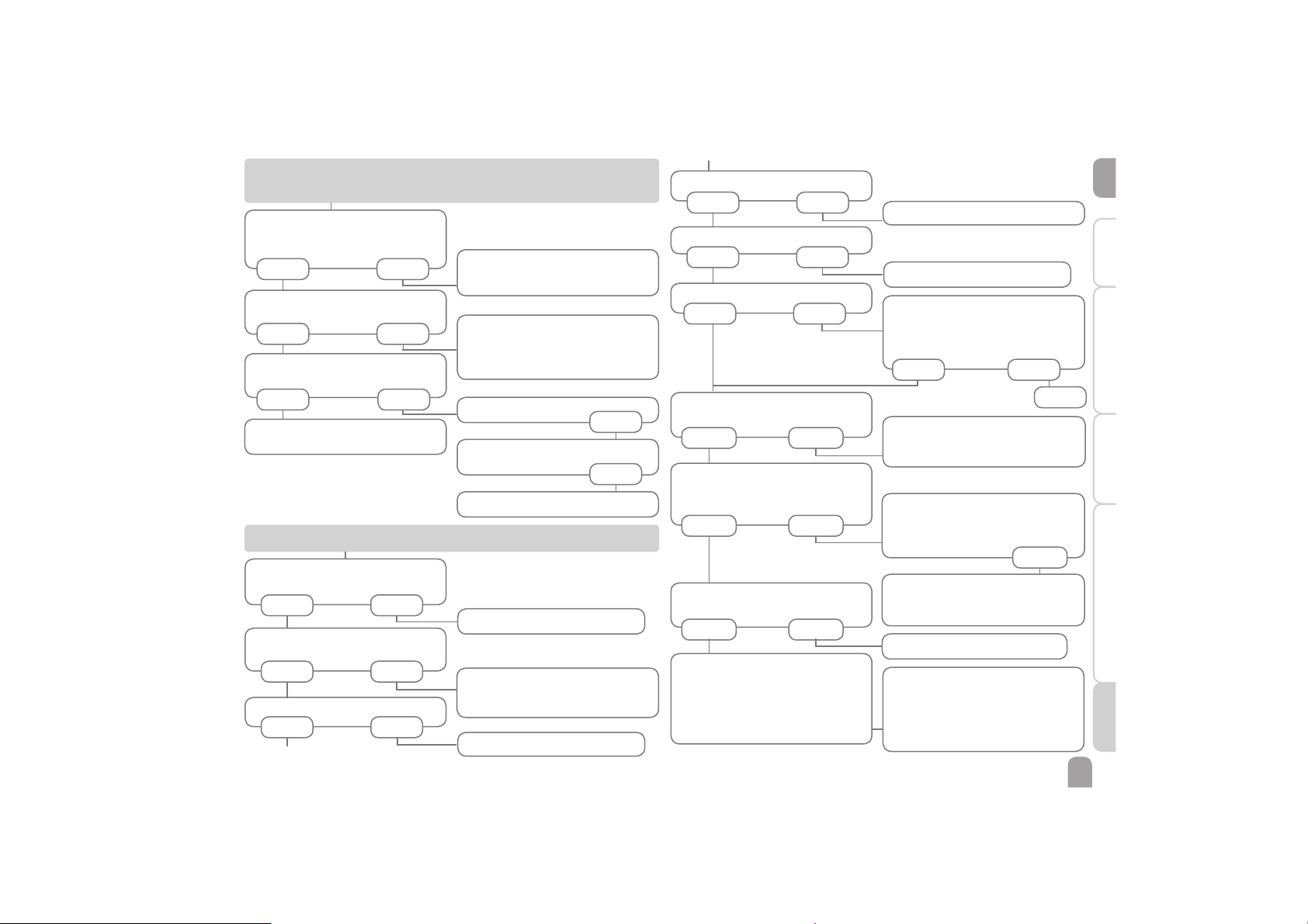
Pump is overheated, but no heat transfer from the collector to the store, flow
and return have the same temperature; perhaps also bubbling in the lines.
Air or gas bubbles in the system?
no yes
Is the collector circuit blocked at
the dirt trap?
yes
Clean dirt trap.
Pump starts for a short moment, switches off, switches on again, etc.
Temperature difference at the
controller too small?
no yes
Wrong position of collector
sensors?
yes
Change 'Ton and 'Toff correspond-
ingly.
Mount the collector sensor at solar
flow (warmest collector output); use
immersion sleeve of the respective
collector.
no
no
o.k.
Pump starts up very late.
The temperature difference between store and collector increases enormously during operation; the collector circuit cannot dissipate the heat.
Collector circuit pump defective?
no
yes
Heat exchanger calcified?
yes
Check / replace it.
Decalcify it.
no
Heat exchanger blocked?
yes
no
Clean it.
Heat exchanger too small?
yes
Change 'Ton and 'Toff corre-
spondingly.
Switch-on temperature difference
'Ton too large?
no yes
Vent the system; increase the
system pressure to a static primary
pressure of at least plus 0.5 bar;
if necessary continue to increase
pressure; switch the pump on and off
for a short time.
Plausibility control of the option
tube collector special function.
Replace with correctly sized one.
Non-ideal position of the collector
sensor (e. g. flatscrew sensor instead
of sensor in immersion sleeves).
yes
Activate tube collector function if
necessary.
o.k.
Page 39
en
39
InstallationIndications, functions and optionsMessages Commissioning Operation and function
Is the pump current enabled by the
controller?
LED in Lightwheel® illuminated? If
not, press the right button. Display
illuminated again?
Does the pump start up in manual
operation?
The solar circuit pump does not work, although the collector is considerably
warmer than the store.
yes no
yes
There is no current; check fuses / re-
place them and check power supply.
The adjusted temperature difference for starting the pump is too
high; choose a value which makes
more sense.
no
yesno
Stores cool down at night.
Collector circuit pump runs during
the night?
no yes
Check controller.
Check the non-return valves in the
flow and the return pipe for function-
al efficiency.
Sufficient store insulation?
yes no
Increase insulation.
Insulation close enough to the store?
yes no
Replace insulation or increase it.
Are the store connections insulated?
yes no
Insulate the connections.
Warm water outflow upwards?
no yes
Change connection and let the
water flow sidewards or through a
siphon (downwards); less store losses
now?
no yes
o.k.
a
Collector temperature at night is
higher than the outdoor temperature.
no yes
Controller might be defective -
replace it.
Is the pump stuck?
Turn the pump shaft using a screw-
driver; now passable?
Pump is defective - replace it.
yes
no
Does the DHW circulation run for
a very long time?
no yes
Use the circulation pump with timer
and switch-off thermostat energy-efficient circulation).
Circulation pump and blocking valve
should be switched off for 1 night; less
store losses?
yes no
Check whether the pumps of the after-heating circuit run at night; check
whether the non-return valve is defective; problem solved?
no
Check the non-return valve in
warm water circulation - o.k.
yes no
a
The gravitation circulation in the
circulation line is too strong; insert
a stronger valve in the non-return
valve or an electrical 2-port valve behind the circulation pump; the 2-port
valve is open when the pump is activated, otherwise it is closed; connect
pump and 2-port valve electrically in
parallel; activate the circulation again.
Deactivate pump speed control!
Clean or replace it.
Further pumps which are connected
to the solar store must also be
checked.
Page 40
40
en
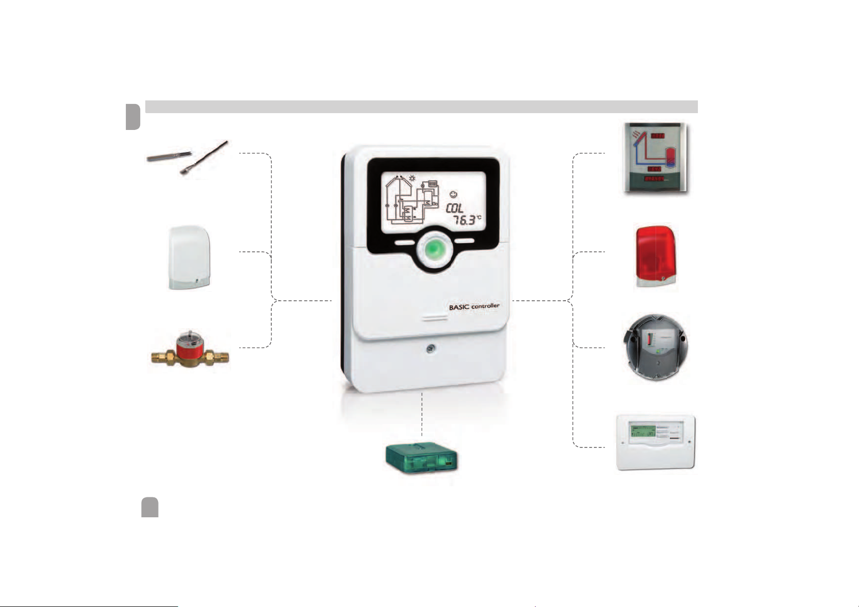
11 Accessories
Sensors
Overvoltage protection
device
V40 fl owmeter
SD3 Smart Display /
GA3 Large Display
AM1 Alarm module
DL3 Datalogger
DL2 Datalogger
VBus® / USB & VBus® / LAN
interface adapters
Page 41

41
en
11.1 Sensors and measuring instruments
Sensors
The product range includes high-precision platinum temperature sensors, flatscrew
sensors, outdoor temperature sensors, indoor temperature sensors, cylindrical clipon sensors, also as complete sensors with immersion sleeve.
Overvoltage protection device
In order to avoid overvoltage damage at collector sensors (e.g. caused by local lightning storms), we recommend installing the overvoltage protection SP10.
V40 flowmeter
The V40 is a measuring instrument for detecting the flow of water or water/glycol
mixtures. After a specific volume has passed, the V40 reed switch sends an impulse
to the calorimeter. The heat quantity used is calculated by the calorimeter using
these impulses and the measured temperature difference with the help of pre-defined parameters (glycol type, concentration, heat capacity, etc.).
11.2 VBus
®
accessories
SD3 Smart Display / GA3 Large Display
The Smart Display is designed for simple connection to controllers with VBus
®
. It
is used for visualising data issued by the controller: collector temperature, store
temperature and energy yield of the solar thermal system. The use of high-efficiency
LEDs and filter glass assures a high optical brilliance and good readability even in
poor visibility conditions and from a larger distance. An additional power supply is
not required. One module is required per controller.
The GA3 is a completely mounted large display module for visualisation of collector- and store temperatures as well as the heat quantity yield of the solar system via
one 6-digit and two 4-digit 7-segment displays. An easy connection to all controllers
with VBus
®
is possible. The front plate is made of antireflective filterglass and is
printed with a light-resistant UV-lacquering. The universal VBus® allows the parallel
connection of 8 large displays as well as additional VBus® modules.
AM1 Alarm module
The AM1 Alarm Module is designed to signal system failures. It is to be connected
to the VBus
®
of the controller and issues an optical signal via the red LED if a failure
has occurred. The AM1 also has a relay output, which can e. g. be connected to a
building management system (BMS). Thus, a collective error message can be issued
in the case of a system failure.
DL3 Datalogger
Be it solar thermal, heating or DHW heat exchange controllers – with the DL3
you can easily and conveniently log system data of up to 6 controllers. Get a comprehensive overview of all controllers connected with the large full graphic display.
Transfer data with an SD memory card, or use the LAN interface to view and
process data on your PC.
DL2 Datalogger
This additional module enables the acquisition and storage of large amounts of data
(such as measuring and balance values of the solar system) over a long period of
time. The DL2 can be configured and read-out with a standard Internet browser
via its integrated web interface. For transmission of the data stored in the internal
memory of the DL2 to a PC, an SD card can be used. The DL2 is appropriate for all
controllers with VBus
®
. It can be connected directly to a PC or router for remote
access and thus enables comfortable system monitoring for yield monitoring or for
diagnostics of faults.
11.3 Interface adapters
VBus
®
/ USB & VBus® / LAN interface adapters
The VBus
®
/ USB interface adapter is the interface between the controller and a
personal computer. With its standard mini-USB port it enables a fast transmission of
system data for processing, visualising and archiving data via the VBus®. A full version
of the ServiceCenter software is included.
The VBus
®
/ LAN interface adapter is designed for the direct connection of the controller to a PC or router. It enables easy access to the controller via the local network of the owner. Thus, controller access and data charting can be effected from
every workstation of the network. The VBus® / LAN interface adapter is suitable for
all controllers equipped with a VBus®. A full version of the ServiceCenter software
is included.
Page 42
42
en
A
Accessories.......................................................................................................................................... 40, 41
Afterheating function ................................................................................................................................ 5
B
Balance values ..................................................................................................................................... 15, 21
Blocking protection ................................................................................................................................. 30
C
Collector cooling ..................................................................................................................................... 23
Collector emergency shutdown ........................................................................................................... 23
Commissioning ......................................................................................................................................... 15
Control lamp ............................................................................................................................................. 11
Cooling function ....................................................................................................................................... 27
D
'T control ................................................................................................................................................. 22
Data communication / Bus ........................................................................................................................ 6
Diaplays ...................................................................................................................................................... 12
Drainback option ..................................................................................................................................... 25
E
Electrical connection ................................................................................................................................. 5
Error messages ......................................................................................................................................... 36
F
Flow rate monitoring .............................................................................................................................. 10
Function control ....................................................................................................................................... 34
H
HE pump .................................................................................................................................................... 10
Holiday function ....................................................................................................................................... 33
L
Language ..................................................................................................................................................... 27
Lightwheel
®
................................................................................................................................................ 11
M
Manual mode ............................................................................................................................................. 30
Menu overview ......................................................................................................................................... 27
Menu structure ......................................................................................................................................... 11
Messages .................................................................................................................................................... 36
MicroSD ..................................................................................................................................................... 14
Minimum and maximum temperatures ............................................................................................... 10
Monitoring-Display .................................................................................................................................. 21
Mounting .................................................................................................................................................... 12
N
Night circulation ....................................................................................................................................... 27
O
Operating days .......................................................................................................................................... 21
P
Priority logic .............................................................................................................................................. 29
R
Resetting balance values ......................................................................................................................... 12
Return preheating .................................................................................................................................... 28
S
Sensor type ................................................................................................................................................ 32
Speed control ............................................................................................................................................ 22
Spreaded loading ...................................................................................................................................... 33
Successive loading .................................................................................................................................... 14
System overview ...................................................................................................................................... 13
System screen ........................................................................................................................................... 22
T
Technical data .............................................................................................................................................. 6
Temperature differential control ('T control) .................................................................................... 4
Thermal disinfection ................................................................................................................................ 22
Time and date ........................................................................................................................................... 20
Troubleshooting ........................................................................................................................................ 37
12 Index
Page 43

43
en
Page 44
Distributed by:
HR Solar
Leehove 4
2678 MC De Lier
Niederlande
tel 0031 0174-523303
fax 0031 0174384687
[email protected]
www.hrsolar.nl
© All contents of this document are protected by copyright.
 Loading...