

Page 1
VS III™
User Manual
English
Respiratory Care solutions
Making quality of care easy
Page 2

Respiratory Care solutions
Making quality of care easy
Page 3

Contents
1 Introduction . . . . . . . . . . . . . . . . . . . . . . . . . . . . . . . . . . . . . . . 1
1.1 Definitions 1
1.2 User/Owner responsibility 1
1.3 Medical information 2
2 Description of the device . . . . . . . . . . . . . . . . . . . . . . . . . . . . 3
2.1 Components 3
2.2 Your device 4
2.3 Respiratory circuit 7
3 Connection procedures . . . . . . . . . . . . . . . . . . . . . . . . . . . . . 7
3.1 Connecting to a power supply 8
3.2 Connecting the respiratory circuit 9
3.3 Connecting the mask 11
3.4 Example of a fully-assembled system 11
4 How to use . . . . . . . . . . . . . . . . . . . . . . . . . . . . . . . . . . . . . . 12
4.1 Starting ventilation 12
4.2 Switching programs (during ventilation) 13
4.3 Viewing data (during ventilation) 14
4.4 Setting the date and time (while ventilation is stopped) 15
4.5 Turning off the device 16
5 Cleaning and maintenance . . . . . . . . . . . . . . . . . . . . . . . . . 17
6 Troubleshooting . . . . . . . . . . . . . . . . . . . . . . . . . . . . . . . . . . 19
7 Technical specifications . . . . . . . . . . . . . . . . . . . . . . . . . . . . 21
7.1 Dimensions 21
7.2 Weight (without external power supply) 21
7.3 Power supply 21
7.4 Transport 22
8 Appendix . . . . . . . . . . . . . . . . . . . . . . . . . . . . . . . . . . . . . . . . 22
9 Symbols displayed on the screen . . . . . . . . . . . . . . . . . . . . 23
Index . . . . . . . . . . . . . . . . . . . . . . . . . . . . . . . . . . . . . . . . . . . 25
iii
Page 4

iv
Page 5

1 Introduction
Please read this manual carefully before using the device.
This manual is provided with the VS III™ device you have received. It
does not in any way replace the clinical manual supplied to your
physician or HME provider.
The VS III is designed to provide ventilation to all patients, whether or not
they are ventilator-dependent. It can deliver invasive ventilation (via a
tracheostomy tube, for example) or non-invasive ventilation (via a mask
or mouthpiece, for example); however, the illustrations and text describe
mask setups only.
1.1 Definitions
This manual contains special terms and icons that appear in the margins
to draw your attention to specific and important information.
CAUTION
Explains special measures for the safe and effective use of the
device.
WARNING
Alerts you to possible injury.
Note: Is an informative or helpful note.
: Signals an action for you to perform.
1.2 User/Owner responsibility
The owner or user of this device shall have sole responsibility and liability
for any injury to persons or damage to property resulting from:
• The device being set up, operated or cleaned in a manner which does
not comply with the instructions provided
• The device being set up, maintained or altered by unauthorised
persons and/or in a manner which does not comply with the
instructions.
Introduction
1
Page 6

1.3 Medical information
Purpose of your ventilation device
The VS III is intended to ventilate both adults and children. Patients may
use it at home and/or in a hospital.
The device is used with either a single or double respiratory circuit.
Two ventilation programs can be set up by your physician. You can
switch from one to the other while ventilation is running.
Warnings
• This manual must be read and understood in full before the device is
used.
• The advice contained in this manual does not replace the instructions
given by your prescribing physician (or HME provider), who will
already be familiar with the operation of the device through the
clinical manual provided.
• The device settings must be entered by competent and trained staff
under the supervision of a physician.
• The device must be used with the accessories recommended by the
manufacturer and by your prescribing physician. The use of
inappropriate accessories is likely to affect the operation of the
device.
• If you have any questions about setting up, operating or maintaining
your ventilator or its accessories, contact your HME provider.
• The ventilator must be transported in its travel bag.
• In the case of externally visible faults, cease using the device.
• If the performance of the device becomes erratic, and you find it
difficult to breathe or trigger a breath, contact your HME provider.
• To avoid the risk of electrocution, do not open the device casing.
Repairs and internal servicing should only be performed by an
authorised service agent.
• If there is interference on the electrical network, operate the
ventilator on battery power.
• Your HME provider must ascertain the electromagnetic
characteristics of the environment in which this ventilator will be
used. In particular, your HME provider must ensure that:
• When the ventilator is operated in proximity to other electrical
devices, including cell phones, there is no interference, and the
ventilator performs correctly
• The ventilator is never placed on or under other devices
2
Page 7
• There is an adequate distance between the ventilator and other
P
Your device
Travel bag Interface (such as a mask
or tracheostomy tube)
External power
supply unit
Respiratory circuit
electrical devices in your home.
• In accordance with Directive 2002/96/EC concerning waste electrical
and electronic equipment, this ventilator must be sorted and
disposed of separately from other types of rubbish. It must not be
disposed of with ordinary municipal waste. Contact your HME
provider for more information.
The above are general warnings. Other specific warnings and notes will
be found throughout the text of the manual.
2 Description of the device
2.1 Components
The picture below shows the components available from your HME
provider:
Figure 1: Components available from your HME provider
Description of the device
3
Page 8
2.2 Your device
P
Control panel
(screen and keypad)
Respiratory circuit connection area
Air outlet
Single circuit support with
exhalation and pressure
line connection
Air outlet
Double circuit support (air return)
Front view
Figure 2: Front view of the device (single circuit)
There is a different type of circuit support for double circuits (see next
figure).
4
Figure 3: Detailed view of circuit support (double circuit)
Page 9
Rear view
Dust filter
(air inlet)
Powe r socke t
Oxygen supply:
• Max. pressure:
400 kPa
• Max. flow:
8 L/min
VS III
Alarm Silence
button
LEDs
LCD screen
On/Off
button
Enter button
Adjustment
buttons
Menu button
On the rear of the device, take particular note of the location of the
following:
• The power supply socket
• The dust filter, which you will have to replace (see “Cleaning and
maintenance” on page 17).
CAUTION
Never block the air vents. This symbol appears on the rear
of the device.
Figure 4: Rear view of the device
Device control panel
The device control panel comprises an LCD screen and a keypad.
Figure 5: Detailed view of the control panel
The keypad consists of buttons and LED indicator lights.
The buttons on the keypad are listed in the table below.
Description of the device
5
Page 10
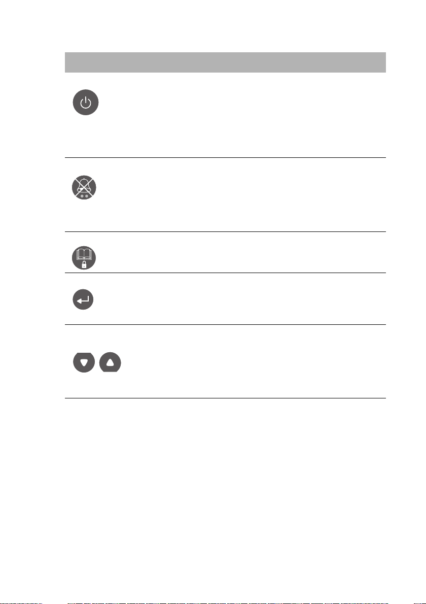
Table 1: Buttons on the device control panel
Button Function
On/Off button Turns the device on.
Stops the device by displaying an options screen.
The user can choose to stop ventilation (if
ventilation is being delivered) or turn off the
device (if ventilation is not being delivered).
Press twice to stop ventilation (press and hold the
second time).
Alarm Silence button Silences the audible alert. After the button is
pressed once, the alarm details stay on the
screen. Press the button a second time to remove
them.
Either the orange or red LED will start flashing,
depending on the type of alarm.
Menu button Opens the menu (viewing data, setting date and
time) or returns to the previous screen.
Enter button Starts ventilation.
Confirms the selected menu or text.
Lets you enter/exit edit mode (for setting the
date).
Adjustment button (Up/
down arrows)
6
Lets you navigate from one selected menu item
to another: selects the previous item (up arrow) or
the next item (down arrow).
In edit mode (date setting): Increases/decreases
the value of a unit. The device beeps when the
maximum or minimum value is reached.
Page 11

Screen appearance while device operating
Displays the
instantaneous
pressure
measurement
(in a bar graph)
27/06/2008 16:48
cm
H2O
9
60
50
40
30
20
10
0
PS.Vs
Stop
Charge level of
internal battery
Shows that the device is
in the Patient menu
(closed padlock)
Time
Message to help you navigate
Current ventilation program
Date displayed as
Day/Month/Year
Figure 6: Appearance of the screen while the device is operating
2.3 Respiratory circuit
According to the ventilation mode prescribed by your physician, you will
be using one of the following:
• A single circuit
• A single circuit with expiratory valve and with or without a pressure
line
• A double circuit.
To determine the type of respiratory circuit prescribed for you and for
instructions on connecting it to the device, see “Connecting the
respiratory circuit” on page 9.
3 Connection procedures
The device must be placed on a flat surface. Ensure the area is dust-free,
and cleared of any objects that could block the dust filter.
CAUTION
Be careful not to place the device where it could be knocked over
or where someone is likely to trip over the power cord.
Connection procedures
7
Page 12

3.1 Connecting to a power supply
1
2
3
Fastening clip
To connect the ventilator to mains power:
1. Plug the power supply connector into the rear of the ventilator (into
the socket marked , see next figure) .
2. Plug the power cord into the power supply box and fasten to
prevent accidental disconnection .
3. Connect the other end of the power cord to the mains .
Figure 7: Connecting the device to the mains power supply
Note: Skip step 2 if using a power supply unit with a fixed power cord.
Your device is now in standby mode.
WARNING
The power cord is equipped with a push-pull locking connector.
Gently pull the power cord to remove from the ventilator. Do not
twist its outer housing.
Notes:
If your device is fitted with a rechargeable internal battery it can be used
without a mains power supply for a period of 2–4 hours, depending on
your settings.
The battery recharges automatically when the device is connected to
the mains supply.
8
Page 13

3.2 Connecting the respiratory circuit
P
1
Corrugated tube
Symbol identifying air outlet
CAUTION
Only the circuit supplied by your HME provider may be used with
your device. Using a different type of circuit may reduce the
effectiveness of your treatment.
Option 1 – Single circuit
1. Connect one end of the corrugated tube firmly to the air outlet, as
shown in the next figure :
Figure 8: Connecting a single circuit to the device
Once your circuit is connected to the device, you can connect the mask
to the other end of the tube.
Option 2 – Single circuit with expiratory valve and
pressure line
1. Connect the air outlet firmly to one branch of the corrugated
tube .
2. Connect the expiratory valve tube (the only one fitted with a
white connector) to the valve control , then turn the connector
slightly to the right to make the connection secure.
3. Finally, connect the other tube (with no connector fitted) to the
pressure line .
Note: If your circuit configuration does not include a pressure line,
this third step will not apply.
Connection procedures
9
Page 14

Figure 9: Connecting a single circuit with expiratory valve and pressure line
P
1
2
3
2
3
Expiratory valve tube
Expiratory valve control
Pressure line
(Prox. P.)
P
Pressure line tube
1
2
Symbol
identifying
air outlet
Symbol
identifying
air return
Once your circuit is connected to the device, you can connect the mask
to the other end of the circuit.
Option 3 – Double circuit
1. Firmly connect one limb of the circuit to the air outlet .
2. Then connect the other limb .
Figure 10: Connecting a double circuit
10
Page 15

Once your circuit is connected to the device, you can connect the mask
P
to the other end of the circuit.
Note: These three circuit configurations may not be exactly as shown in
this illustration. It may also include a humidification system, antibacterial
filter or water traps. Contact your HME provider if you have any
questions about connecting your respiratory circuit.
3.3 Connecting the mask
Refer to the instructions given by your physician or HME provider.
CAUTION
It is essential to use only the mask supplied by your physician or
HME provider.
3.4 Example of a fully-assembled system
Figure 11: Example of a fully-assembled system (single circuit with valve
and pressure line)
If your setup does not have any accessories (oxygen accessories,
external battery or remote alarm), you can now switch your device on
(see next paragraph).
Connection procedures
11
Page 16

4How to use
1
2
VS III
24/08/2008 15:29
cm
H2O
0
60
50
40
30
20
10
0
24/08/2008 15:29
cm
H2O
0
60
50
40
30
20
10
0
Start ventilation
Start ventilation
PS.Vs
Prog1: PS.Vs
Prog2: PS.Vt
VS III
Software version: x.xx
Autotest in progress ...
1500h
Regardless of whether the
device is running on battery or
mains power, press .
The device performs its self
test.
The main screen is displayed.
• Either press to start
ventilation
• Or use to select
“Prog1” or “Prog2”, then
press to start ventilation.
1 program 2 programs
This ventilator and its accessories must be operated in a dust-free
environment and kept away from direct sunlight.
The ventilator is a medical device. To ensure smooth operation, keep the
ventilator out of reach of pets, and ensure children do not have
unsupervised access to it.
You can:
• Turn your device on and off
• Switch from one ventilation program to the other, if your treatment
includes two different programs
• Display data for each ventilation program: the settings and alarm
thresholds entered by your physician, measurements for the
current ventilation program, technical data, and the Event and
Alarm Log.
• Set the date and time.
4.1 Starting ventilation
12
Figure 12: Turning the device on: self test performed and ventilation start
screen displayed with one program (lower left screen) or two programs
(lower right screen)
Page 17

4.2 Switching programs (during ventilation)
1
2
27/09/2008 17:50
cm
H2O
9
60
50
40
30
20
10
0
Prog1: PS.Vs
Prog2: PS.Vt
Stop
27/09/2008 17:50
cm
H2O
11
60
50
40
30
20
10
0
Prog2: PS.Vt
Prog1: PS.Vs
Stop
Confirmation
cm
H2O
9
60
50
40
30
20
10
0
Confirm
No
Yes
Program change?
!
LP
While the device is delivering
ventilation under “Prog1”, press .
On the program change confirmation
screen, use to select “Yes”, then
press to confirm.
The device is now delivering ventilation
under “Prog2”.
27/09/2008 17:50
cm
H2O
11
60
50
40
30
20
10
0
Prog2: PS.Vt
Prog1: PS.Vs
Stop
LP
LPLP
cmH2O
11
27/09/2008 17:50
cm
H2O
11
60
50
40
30
20
10
0
Prog2: PS.Vt
Prog1: PS.Vs
Stop
cmH2O
11
With “Mouthpiece/Speaking”
option deactivated
Symbol displayed when
the “Mouthpiece/Speaking”
option has been selected for
Prog 2 (in valve ventilation
modes only).
With “Mouthpiece/
Speaking” option activated
LP
Figure 13: Switching programs during ventilation
Note: Once the “Mouthpiece/Speaking” option is activated by your
physician, you are able to speak without triggering the low pressure
alarm during expiration.
Ensure that a caregiver is able to supervise the use of the device while
this option is activated.
How to use
13
Page 18

4.3 Viewing data (during ventilation)
1
2
27/08/2008 17:20
cm
H2O
9
60
50
40
30
20
10
0
PS.Vs
Stop
cm
H2O
12
60
50
40
30
20
10
0
Back
PS.Vs
Menu
View settings/alarms
Technical information
Events/Alarms Log
View Monitoring
With the main screen displayed, press
to access the “Menu” screen.
Use to select the option you wish to
display:
• the ventilation settings and alarm
thresholds;
• the measurements (monitoring);
• the technical information or;
• the Event and Alarm Log, then press
to confirm.
cm
H2O
10
60
50
40
30
20
10
0
cm
H2O
0
60
50
40
30
20
10
0
27/08/2008 16:49
cm
H2O
0
60
50
40
30
20
10
0
PS.Vs
View alarm thresholds
min max
f -- 20
bpm
Vt 0.25 0.80
L
FiO2 21 100 %
cm
H2O
0
60
50
40
30
20
10
0
PS.Vs
PEEP 4
fmin 15
Rise t
Vts 0.50 Timax 2.0
Timin 0.3
TgE A U TO
TgI( V ) NO
TgI( P ) AU T O
PS 10
cmH2O
cmH2O
bpm
Ls
s
2
View settings
: Alarm thresholds
: Settings
27/06/2011 16:48
cm
H2O
0
60
50
40
30
20
10
0
DATE & TIME ALL EVENTS CODE
Events #1 to 8 of 17
: Alarms only: Scroll
/
21
25
21
01
3
2
1
0
High FiO2:%FiO2:
High FiO2:%FiO2:
Low FiO2:%FiO2:
Start of ventilation: prog:
Loss of power supply:
Switched to internal battery:
Switched to external supply:
Switched to mains supply:
28/06/2011 18:38:48
28/06/2011 18:54:40
27/06/2011 09:52:43
25/06/2011 08:13:03
24/06/2011 11:06:22
23/06/2011 09:52:23
22/06/2011 10:32:03
21/06/2011 19:55:54
27/06/2011 16:49
cm
H2O
0
60
50
40
30
20
10
0
DATE & TIME ALARM EVENTS CODE
Events #1 to 8 of 11
: All events: Scroll
/
21
25
21
--
--
--
--
--
High FiO2:%FiO2:
High FiO2:%FiO2:
Low FiO2:%FiO2:
Mains supply
Mains supply
Patient disconnection
Patient disconnection
External battery
28/06/2011 18:38:48
28/06/2011 18:54:40
27/06/2011 09:52:43
20/06/2011 08:13:03
20/06/2011 08:13:20
13/06/2011 09:52:23
13/06/2011 09:52:30
01/06/2011 19:55:54
PS.Vs
View Monitoring
f = 15 bpm FiO2 = 21 %
I:E = 1:2.3 Leaks = 0 %
Ti = 1.00 s
Vti = 0.60 L
MV
I
= 9.0 L/min
Patient hours= 1650h
Machine hours= 2000h
Turbine wear= 0%
Circuit type= Valve
Software version= x.xx
Ventilation settings and alarm thresholds:
Measurements:
Technical information:
Event and Alarm Log:
Figure 14: Viewing data
The following figure shows the screens for each option:
14
Figure 15: Information screens (examples)
For any further information, please contact your HME provider.
Page 19

4.4 Setting the date and time (while ventilation is
3
4
1
2
cmH2O
0
60
50
40
30
20
10
0
24/08/2008 16:53
cm
H2O
0
60
50
40
30
20
10
0
25/08/2008 16:54
cm
H2O
0
60
50
40
30
20
10
0
24/08/2008 16:53
24/08/2008 16:48
cm
H2O
0
60
50
40
30
20
10
0
Start ventilation
PS.Vs
Date and Time
Day: 24
Month: 8
Year: 2008
Hour: 10
Minute: 13
Date and Time Setting
Day: 25
Month: 8
Year: 2008
Hour: 10
Minute: 13
Date and Time Setting
Day: 25
Month: 8
Year: 2008
Hour: 10
Minute: 13
Back
PS.Vs
Menu
View settings/alarms
Technical information
Events/Alarms Log
Date and Time Setting
cmH2O
0
60
50
40
30
20
10
0
The “Day”, “Month”, “Year”, “Hour” and
“Minute” fields appear. The “Day” field is
selected by default.
Press to edit the “Day” field.
The highlighted area reduces in size to cover
only the editable field and the words “Set Date
and Time” are displayed in the message area.
Use to change the day of the month.
Press to confirm the change.
The highlighted area returns to its original size
and moves to the next field.
Press to access the “Menu” screen.
Use to select “Date and Time Setting”,
then press .
stopped)
Figure 16: Setting the date and time
Repeat steps 3 and 4 for the “Month”, “Year”, “Hour” and “Minute”
fields.
Press twice to return to the main screen.
How to use
15
Page 20

4.5 Turning off the device
27/09/2008 16:48
cm
H2O
9
60
50
40
30
20
10
0
27/09/2008 17:50
cm
H2O
9
60
50
40
30
20
10
0
27/09/2008 16:48
cm
H2O
0
60
50
40
30
20
10
0
27/09/2008 17:50
cm
H2O
0
60
50
40
30
20
10
0
cm
H2O
6
60
50
40
30
20
10
0
!
Stop ventilation 1s
Turn off ventilator
Cancel
Disconnect O2 before stop!
Confirm
PS.Vs
Stop
Stop
Start ventilation
Start ventilation
PS.Vs
Prog1: PS.Vs
Prog2: PS.Vt
Prog1: PS.Vs
Prog2: PS.Vt
Confirmation
1 program
2 programs
Press .
Press again and hold
for 1 second, or confirm
“Stop ventilation” by
pressing .
The message “Wait a few
moments” is displayed.
The main screen displays:
• Either the current
program (if only one
program is configured)
• Or the currently selected
program (if two programs
are configured).
Stopping ventilation
Figure 17: Stopping ventilation
16
Note: When stopping ventilation, the device will beep continuously.
Press to confirm.
Page 21

Shutting down the device
1
2
27/09/2008 19:17
cm
H2O
0
60
50
40
30
20
10
0
PS.Vs
Start ventilation
27/09/2008 19:18
cm
H2O
9
60
50
40
30
20
10
0
PS.Vs
Stop
cm
H2O
0
60
50
40
30
20
10
0
!
cm
H2O
9
60
50
40
30
20
10
0
!
Confirmation Confirmation
Turn off ventilator 1s
Cancel
Disconnect O2 before stop!
Stop ventilation 1s
Turn off ventilator
Cancel
Disconnect O2 before stop!
Confirm
Confirm
While ventilation is
stopped
During ventilation
Press .
Press again and hold
for 1 second (left-hand
screen), or confirm “Turn
off ventilator” by pressing
(right-hand screen).
The alarm will sound.
The message “Wait a few
moments” is displayed
(you have to wait for the
circuit to empty), then the
device will beep. Press .
Wait a few moments
Figure 18: Shutting down the device
5 Cleaning and maintenance
We recommend that you maintain your device and accessories regularly.
CAUTION
If you use any of the following accessories:
• Mask
• Humidifier
• Antibacterial filter
• Water traps,
follow the instructions provided in the manual for your accessory,
and the instructions of your physician or HME provider.
Cleaning and maintenance
17
Page 22

CAUTION
Do not use bleach-, chlorine-, alcohol-, or aromatic-based
solutions (including all scented oils), or moisturising or
antibacterial soaps. These solutions may cause hardening and
reduce the life of the plastic components.
Table 2: Frequency of maintenance
Component Frequency Maintenance
Respiratory circuit Follow specific recommendations from your HME
provider.
Mask Before first use, then
weekly.
Mask headgear Monthly. Wash the headgear in
Exterior of the
device
P
Dust filter Check once a month that
Monthly. Wipe with a damp cloth
it is in good condition and
replace if necessary.
Replace at least once
every six months.
Clean the mask in warm
soapy water, rinse well
and dry thoroughly.
warm soapy water.
and soapy water.
CAUTION
Keep the device away
from water.
Pull the filter out of its
housing and replace with
a new filter.
WARNING
To avoid any risk of electric shock, never immerse the device or
power cord in water. Always unplug the device before cleaning
and be sure that it is dry before plugging it back in.
CAUTION
Do not attempt to open the device casing. Repairs and internal
servicing should only be performed by an approved technician.
18
Page 23

6 Troubleshooting
Alarms will alert you to any problems with your device. The instructions
in this section will help you to identify the cause of the problem. If the
fault persists or cannot be identified, do not try to open the device.
Instead, contact your HME provider.
If an alarm is triggered you will notice the following:
• An audible signal will sound
• The symbol will appear at the top of the screen, followed by
the name of the alarm
• The red or orange LED will flash.
If you know which alarm has been triggered, consult the following
tables, otherwise contact your HME provider.
Table 3: Ventilation alarms (not an exhaustive list)
Alarm name Cause Solution
Mains Disconnect
Ext. Battery Lost
Low battery
Empty Battery
Connect Circuit
The mains power cord
has been disconnected.
The external battery cord
has been disconnected.
This alarm can be
triggered only if an
external battery is
connected to your
device.
The charge level of the
internal battery is low
(less than 20%).
The internal battery is flat
(charge level less than
5%).
A component in your
patient circuit is wrongly
connected or is
disconnected.
Reconnect the mains
power cord.
Reconnect the external
battery cord.
Connect the device to
the mains power supply
without delay to
recharge the internal
battery.
Connect the device to
the mains power supply
immediately.
Reconnect the patient
circuit.
Troubleshooting
19
Page 24

Alarm name Cause Solution
The connected circuit is
different from the one for
Change Circuit
Prox. P. Lost
Low Pressure
High Pressure
Low Vti or Low Vte
High Vti High inspired volume. Check your circuit and
which the device is
configured.
The pressure line is
disconnected (see Figure
9 on page 10).
This alarm also indicates
a wrongly connected or
disconnected patient
circuit.
A component in your
respiratory circuit is
blocked.
Low inspired volume or
low expired volume.
Connect the correct
circuit.
Reconnect the pressure
line.
Reconnect the patient
circuit.
Clean, empty or replace
the components of your
respiratory circuit.
Contact your HME
provider if this alarm
persists.
Check your circuit.
make sure there are no
leaks.
Table 4: Technical alarms (not an exhaustive list)
Alarm name Cause Solution
Tech [n] Technical alarm. The
alarm number indicates
the type of incident.
Turbine Alarm indicating that the
turbine has stopped.
The temperature of the
internal battery is too
Temp Out Of
Range
Check Date&Time
20
high or too low.
The charge level of the
backup battery (internal
clock memory) is low.
Contact your HME
provider and give the
number of the alarm.
Contact your HME
provider.
Contact your HME
provider.
Connect the device to
the mains power supply
without delay and check
the date and time.
Page 25

7 Technical specifications
7.1 Dimensions
275 mm
145 mm
P
221 mm
7.2 Weight (without external power supply)
2.9 kg
P
7.3 Power supply
Mains power
Input: 100–240 V AC, 50/60 Hz, Max. 1.8 A.
Output: 30 V DC; 2.33 A.
CAUTION
Use only the power supply unit provided with the device.
Internal battery
NiMH 24 V, 2.1 Ah.
Internal battery life
2–4 hours, depending on settings.
External battery
26 V DC ± 10, Max. 3 A.
Technical specifications
21
Page 26

External battery life (ResMed Power Station)
At least four times longer than the life of the internal battery (when the
internal battery is fully charged).
7.4 Transport
Storage and transport temperature
-10 to +50°C.
Relative humidity
10 to 90%.
CAUTION
This device is fragile and must be kept dry. It must be transported
in its carry bag together with its accessories.
Normal use
• Operating temperature: +5°C to +40°C.
• Ambient relative humidity: 10%–95%.
• Atmospheric pressure: 600–1100 hPa.
Extraordinary use
• Operating temperature: -5°C to +40°C.
Note: Between -5°C and +5°C, it takes the device 30 minutes to reach
optimal performance. To obtain optimal performance immediately in
this temperature range, operate the device at ambient temperature
prior to use.
8 Appendix
Travelling with your device
For long journeys it is advisable to carry your device in its travel bag, with
the following accessories:
• The mains power cord and the external power supply
• The circuit and its accessories
• The mask
• The oxygen coupling (if you use oxygen).
If you intend to travel by air with the device, ask your HME provider about
the required formalities.
22
Page 27

9 Symbols displayed on the screen
LP
1500h
40
30
20
10
0
<Alarm>
Symbol Meaning
External power supply (mains)
External battery
Internal battery (the device is detecting whether
the battery is charging or discharging)
Up arrow indicates the internal battery is charging
(coloured black or white depending on the charge
level)
Down arrow indicates the internal battery is
discharging
Indicates the Patient menu
Indicates that the LP expi alarm was deactivated
following the selection of the “Mouthpiece/
Speaking” option.
Patient hours on the welcome screen
Signals a confirmation or reset screen
!
Bar graph with pressure bar (cmH
Alarm symbol followed by the name of the alarm
Menu button
Enter button
On/Off button
Symbols displayed on the screen
O)
2
23
Page 28

24
Page 29

Index
A
air outlet 10
air return
Alarm Silence button
4
6
B
battery life
8, 21
C
circuit support (for double circuit)
control panel
corrugated tube
5
9
D
double circuit
dust filter
2, 4, 7
7
E
Event and alarm log
expiratory valve
14
9, 10
H
HME provider 1
I
internal battery
8
K
5
keypad
R
respiratory circuit
9, 10, 18
S
5
screen
single circuit
standby
2, 7, 10
8
T
4
troubleshooting
19
W
warnings 2
L
LEDs 5
M
maintenance
dust filter 18
headgear
mask
18
18
respiratory circuit
mask
11
medical information
monitoring
14
O
On/Off button
6
P
pressure line
9, 10
18
2
Index
25
Page 30

26
Page 31

Respiratory Care solutions
Making quality of care easy
Page 32

0123
NOT014930-4 2012-01
VS III
USER
ENG
HME provider contact details
ResMed Paris, 240 rue de la Motte 77550 Moissy-Cramayel, France.
See www.resmed.com for other ResMed locations worldwide. Protected by the following patents: FR 2839893, US 7891353. VS
III is a registered trademark of ResMed Paris. The technical specifications may be changed without notice. © 2012 ResMed Paris.
Global leaders in sleep and respiratory medicine www.resmed.com
 Loading...