

Page 1
User guide
(RCM1)
English
Page 2
A
AirView
RCM
Compatible device*
*
兼容装置 / 相容裝置
B
1
2
6
AirView
3
C
1
4
5
2
3
4
7
8
D
Page 3
ENGLISH
Introduction
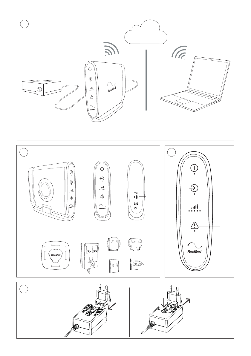
Refer to illustration A.
ResMed Connectivity Module (RCM) provides cellular connection between a compatible ResMed
ventilation device and the ResMed AirView
RCM sends therapy and device data recorded in the ventilation device to the cloud-based AirView
™
system.
system once a day from home, wirelessly and automatically, to assist the remote display of patient
data.
RCM also sends data to AirView on demand when requested via AirView (eg, for remote display and
troubleshooting).
Compatible devices
RCM is compatible with the following ventilation devices:
• Astral
• Stellar
™
100/150
™
100/150.
Intended use
RCM is intended to be used in the home environment, for the collection and transmission of
respiratory data to AirView. RCM will not control any clinical devices, nor provide interpretation of
data.
RCM is not intended for use on an aircraft.
General warnings and cautions
The following are general warnings and cautions. Specific warnings, cautions and notes appear with
the relevant instructions in the guide.
WARNING
• Only use the power supply unit and plug blade attachments provided with RCM.
• Beware of electrocution. Do not immerse RCM or any of its components in water. Always
unplug RCM before cleaning and make sure that all parts are dry before plugging it back in.
• Do not open or modify the device. There are no user serviceable parts inside. Repairs and
servicing should only be performed by an authorized ResMed service agent.
CAUTION
Do not use RCM outdoors.
English 1
Page 4
RCM at a glance
1.
Stand
6.
Wall mount
2.
Wall mounting socket
7.
Power Supply Unit (PSU)
3.
Indicator panel
8.
Plug blade attachments
4.
Micro-USB port
9.
USB cable (not shown)
5.
Power inlet
Refer to illustration B.
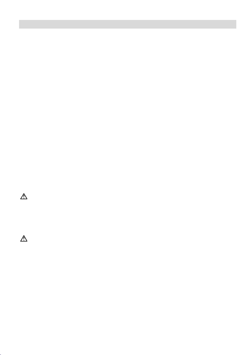
Indicators
Refer to illustration C.
RCM provides indication of the current operating state. When the Power and Vent. Input indicators
illuminate and you have network reception, RCM is ready to use.
Indicator Status
1 Power – Green
Indicates whether RCM is powered on.
On: The power is on.
Off: The power is off.
2 Vent. Input – Blue
Indicates whether RCM is connected to the powered-on
ventilation device.
On: Connected to the ventilation device.
Off: Disconnected from the ventilation device.
Blinking: Establishing connection to the ventilation device.
3 Signal – Blue
Indicates connectivity to the cellular network and the signal
strength.
On: Connected to the cellular network. The signal strength
is indicated by the number of blue dots (more dots mean a
stronger signal).
Off: No cellular network detected.
4 Error – Yellow
Indicates whether RCM has an error.
Note: The Vent. Input and Signal indicators will dim in 5 minutes and will return to full brightness
when RCM is connected to the ventilation device or powered on again.
On: An error has occurred.
Off: No error
Assembling the PSU
Refer to illustration D.
1. Insert the plug blade attachment suitable for your region into the PSU.
2. To remove the plug blade attachment from the PSU, press the button under the arrow and slide
it out.
CAUTION
• Do not leave the plug blade attachment in a power outlet alone.
• Do not plug the PSU upside down into a power outlet. Ensure that the power cord extends
downward.
2
Page 5

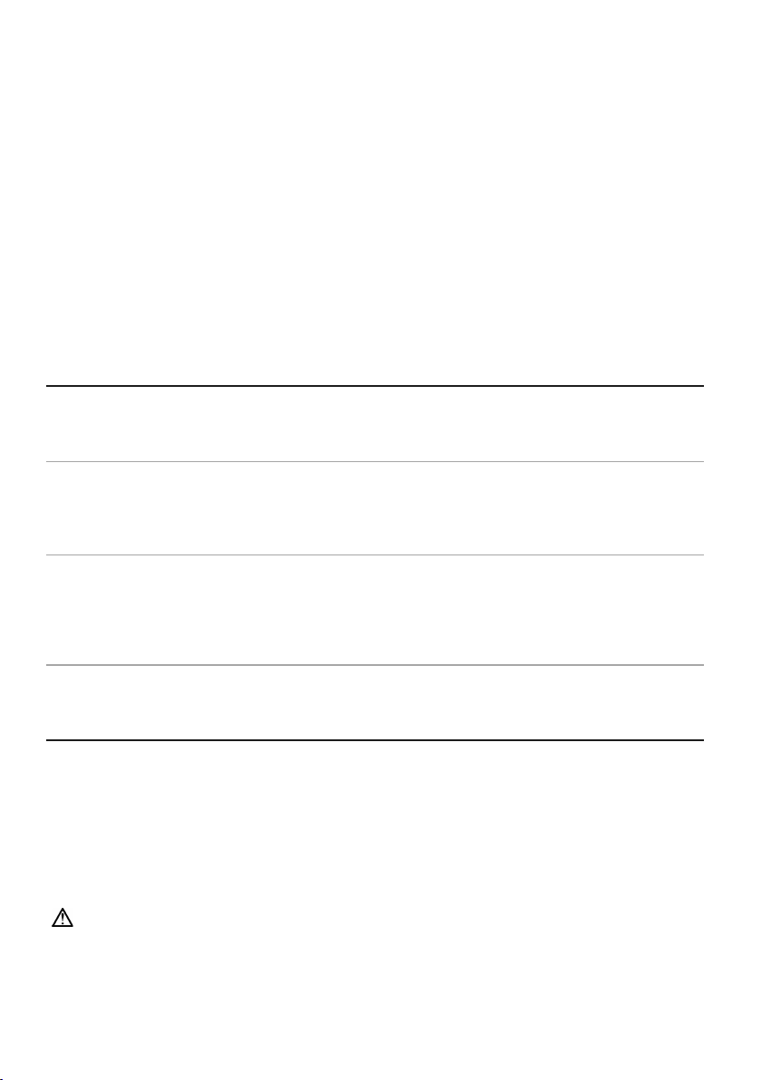
Setup
Refer to illustration E.
RCM can only be connected to one ventilation device at a time.
1. Connect the RCM to the power using the PSU. Ensure that the Power indicator illuminates.
2. Position RCM where the Signal indicator shows that you have network reception, and ensure
that RCM is:
• more than 2 cm away from the body during operation.
• in an area that will not be affected by moisture.
• ideally 30 cm away from the ventilation device or other electrical equipment and 3'3" (1 m)
from mobile communication devices.
3. Ensure that the RCM is secured with the stand or wall mount. Refer to the Using the stand/wall
mount section.
4. Connect one end of the USB cable to the micro USB port of RCM, and the other end to the mini
USB port at the rear of the powered-on ventilation device (refer to the illustration). Ensure that
the Vent. Input indicator illuminates.
5. To ensure correct times are shown in AirView, ensure that the clock on the ventilation device is
correct (change if appropriate).
Notes:
• For further assistance, contact your care provider or ResMed representative.
• To stop RCM, unplug the power cord from the power outlet.
Using the stand/wall mount
Stand
Refer to illustration F.
1. Place the stand on a stable level surface.
2. Insert the longer edge of the stand into RCM, ensuring that it clicks into place.
3. To remove the stand, release the clip on the stand.
Wall mount
Refer to illustration G.
Use appropriate fittings to attach the wall mount. For example, use the round holes or the slots of
the wall mount for screws or cable ties (not provided).
WARNING
Ensure that the wall mount is securely fixed in place.
1. Hold RCM at an angle and push it onto the wall mount. Adjust the angle to fit RCM in place.
2. Turn RCM clockwise until it clicks into place.
3. To remove RCM from the wall mount, turn it counterclockwise.
English 3
Page 6

Sending data to AirView
RCM automatically sends the previous 24 hours of data to AirView once a day from approximately
12 pm (based on the clock of the connected ventilation device).
If automatic data transmission is missed or interrupted, it will resume when the connection is
re-established. No data will be lost.
To ensure daily automatic data transmission, ResMed recommends you to connect RCM once a day
for one hour, with the Vent. Input and Signal indicators on.
Note: Data more than seven calendar days old will not be sent to AirView.
Cleaning and maintenance
The exterior of RCM and the PSU can be cleaned with a damp cloth and an approved mild cleaning
solution.
The following cleaners and disinfectants are compatible for use when cleaning external surfaces of
RCM:
• isopropyl alcohol
• bleach (1:10) (may also be known as ‘diluted hypochlorite’).
Always follow the manufacturer's recommended cleaning instructions.
WARNING
Ensure that the RCM and PSU are dry before reconnecting to the power outlet and ventilation
device.
Troubleshooting
Problem/possible cause Solution
The Power indicator does not illuminate.
The Vent. Input indicator does not illuminate.
Check that the PSU is connected correctly to the power outlet and the
rear of RCM.
Check that the plug blade attachment is inserted into the PSU correctly.
Check that the PSU is the one provided with RCM.
Check that the ventilation device is turned on.
Check that the USB cable is connected correctly to the rear of RCM and
the ventilation device.
The Signal indicator does not illuminate.
Change the position of RCM.
Check that you have network reception.
Ensure that RCM is ideally 12" (30 cm) away from the ventilation device
or other electrical equipment.
The Error indicator is on.
Switch RCM off, then on again, to see if this removes the error. If the
Error indicator displays again, contact your care provider or ResMed
representative.
Automatic data transmission was interrupted or
missed at 12 pm (eg, no signal,
RCM/ventilation device disconnected or
Re-establish the connection between RCM, ventilation device, and
AirView (refer to the Setup section). Automatic data transmission will
resume to send any outstanding data.
powered off).
If the problem cannot be solved, contact your care provider or ResMed representative.
4
Page 7

Technical specifications
Dimensions (H x W x L)
RCM only:134 mm x 44 mm x 150 mm
Weight
RCM only: 280 g
Power supply unit (PSU)
AC 100–240 V, 0.35–0.70 A, 50–60 Hz
Housing construction
Flame retardant engineering thermoplastic and silicon
Environmental conditions
Electromagnetic compatibility
Product complies with all applicable electromagnetic compatibility
devices are kept at least 1 m away from the device.
IEC 60601-1 classification
Non-transit operable, portable equipment
Compatible software versions
AirView: 4.1 or higher
Wireless module
Declaration of Conformity to
ResMed declares that the RCM device is in compliance with the essential
www.resmed.com/downloads/devices.
Separation
The RCM device should be used at a minimum distance of 2 cm from the body
and ideally 30 cm from the ventilation device during operation.
Design life
5 years
The stand will add 3 mm to the height and 6 mm to the width.
The stand will add 30 g and the wall mount will add 10 g.
DC 24 V, 1.25 A
Cable length 1.8 m
Class II, suitable for continuous operation
Typical power consumption; <3W
Maximum power consumption: <5W
Operating temperature:
Operating humidity:
Operating altitude:
Storage and transport temperature:
Storage and transport humidity:
0oC to +40oC
10%–95% non-condensing
Sea level to 3000 m
o
C to +70oC
-25
10%–95% non-condensing
requirements (EMC) according to IEC60601-1-2, for residential, commercial and
light industry environments. It is recommended that mobile communication
Astral: SX544-0401 or higher
Stellar: SX483-0250 or higher
Technology used: 3G/2G
1999/5/EC (DoC to the R&TTE
Directive)
requirements and other relevant provisions of Directive 1999/5/EC. A copy of
the declaration of conformity (DoC) can be found on
The RCM and PSU do not contain any serviceable parts.
Note: The manufacturer reserves the right to change these specifications without notice.
Guidance and manufacturer’s declaration electromagnetic
emissions and immunity
Medical electrical equipment needs special precautions regarding EMC and needs to be installed
and put into service according to EMC information provided in this document.
English 5
Page 8

Guidance and manufacturer’s declaration—electromagnetic emissions
Emissions test
Compliance
Electromagnetic environment — guidance
RF emissions CISPR 11
Group 1
The device uses RF energy only for its internal
electronic equipment.
Immunity test
IEC60601-1-2 test
level
Compliance level
Electromagnetic environment — guidance
Electrostatic
IEC 61000-4-2
±6 kV contact
±6 kV contact
Floors should be wood, concrete or ceramic tile. If
humidity should be at least 30%.
Electrical fast
±2 kV for power
lines
±2 kV for power supply
lines
Mains power quality should be that of a typical
IEC60601-1-2:2007
These devices are intended for use in the electromagnetic environment specified below. The
customer or the user of the device should assure that the device is used in such an environment.
function. Therefore, its RF emissions are very low and
are not likely to cause any interference in nearby
RF emissions CISPR 11 Class B The device is suitable for use in all establishments,
Harmonic Emissions IEC 61000-3-2 Class A
Voltage Fluctuations/Flicker Emissions
IEC 61000-3-3
Complies
including domestic establishments and those directly
connected to the public low-voltage network that
supplies buildings used for domestic purposes.
WARNING
• The device should not be used adjacent to or stacked with other equipment. If adjacent or
stacked use is necessary, the device should be observed to verify normal operation in the
configuration in which it will be used.
• The use of cables other than those specified for the device is not recommended. They may
result in increased emissions or decreased immunity of the device.
Guidance and manufacturer’s declaration – electromagnetic immunity
These devices are intended for use in the electromagnetic environment specified below. The
customer or the user of the device should assure that the device is used in such an environment.
discharge (ESD)
transient/burst
IEC 61000-4-4
±8 kV air
supply lines
±1 kV for input/output
±8 kV air
lines
±1 kV for input/output
floors are covered with synthetic material, the relative
commercial or hospital environment.
Surge
IEC 61000-4-5
6
±1 kV differential
mode
±2 kV common mode
±1 kV differential
mode
±2 kV common mode
Mains power quality should be that of a typical
commercial or hospital environment.
Page 9

Immunity test
IEC60601-1-2 test
level
Compliance level
Electromagnetic environment — guidance
Voltage dips,
<5% Ut (>95% dip in
100V
Mains power quality should be that of a typical
Power
3 A/m
3 A/m
Power frequency magnetic fields should be at levels
Conducted RF
3 Vrms
3 Vrms
Portable and mobile RF communications equipment
frequency of the transmitter.
Radiated RF
10 V/m
10 V/m
Recommended separation distance
symbol:
short
interruptions
and voltage
variations on
power supply
input lines
IEC 61000-4-11
frequency
(50/60 Hz)
magnetic field
IEC 61000-4-8
IEC 61000-4-6
IEC 61000-4-3
Ut) for 0.5 cycle
40% Ut (60% dip in
Ut) for 5 cycles
70% Ut (30% dip in
Ut) for 25 cycles
<5% Ut (>95% dip in
Ut) for 5 sec
150 kHz to 80 MHz
80 MHz to 2.5 GHz
240V
150 kHz to 80 MHz
80 MHz to 2.5 GHz
commercial or hospital environment.
If the user of the device requires continued operation
during power mains interruptions, it is recommended
that the device be powered from an uninterruptible
power source.
characteristic of a typical location in a typical
commercial or hospital environment.
should be used no closer to any part of the device,
including cables, than the recommended separation
distance calculated from the equation applicable to the
d = 0.35 √P
d = 0.35 √P 80 MHz to 800 MHz
d = 0.70 √P 800 MHz to 2.5 GHz
Where (P) is the maximum output power rating of the
transmitter in watts (W) according to the transmitter
manufacturer and d is the recommended separation
distance in meters (m). Field strengths from fixed RF
transmitters, as determined by an electromagnetic site
a
survey,
should be less than the compliance level in
each frequency range.
b
Interference may occur in the
vicinity of equipment marked with the following
a
Field strengths from fixed transmitters, such as base stations for radio (cellular/cordless) telephones and land mobile
radios, amateur radio, AM and FM radio broadcast and TV broadcast cannot be predicted theoretically with accuracy. To
assess the electromagnetic environment due to fixed RF transmitters, an electromagnetic site survey should be considered.
If the measured field strength in the location in which the device is used exceeds the applicable RF compliance level above,
the device should be observed to verify normal operation. If abnormal performance is observed, additional measures may
be necessary, such as reorienting or relocating the device.
b
Over the frequency range 150 kHz to 80 MHz, field strengths should be less than 10 V/m.
Notes:
• Ut is the AC mains voltage prior to application of the test level.
• At 80 MHz and 800 MHz, the higher frequency range applies.
• These guidelines may not apply in all situations. Electromagnetic propagation is affected by
absorption and reflection from structures, objects and people.
English 7
Page 10

Recommended separation distances between portable and mobile RF
Rated maximum output
Separation distance according to frequency of transmitter (m)
150 kHz to 80 MHz
80 MHz to 800 MHz
800 MHz to 2.5 GHz
0.01
0.035
0.035
0.070
0.1
0.11
0.11
0.22
1
0.35
0.35
0.70
10
1.1
1.1
2.2
100
3.5
3.5
7.0
communications equipment and the device
These devices are intended for use in an environment in which radiated RF disturbances are
controlled. The customer or the user of the device can help prevent electromagnetic interference by
maintaining a minimum distance between portable and mobile RF communications equipment
(transmitters) and the device as recommended below, according to the maximum output power of
the communications equipment.
power of transmitter (W)
d = 0.35 √P
d = 0.35 √P
d = 0.7 √P
For transmitters rated at a maximum output power not listed above, the recommended separation
distance d in metres (m) can be determined using the equation applicable to the frequency of the
transmitter, where P is the maximum output power rating of the transmitter in watts (W) according
to the transmitter manufacturer.
Notes:
• At 80 MHz and 800 MHz, the separation distance for the higher frequency range applies.
• These guidelines may not apply in all situations. Electromagnetic propagation is affected by
absorption and reflection from structures, objects and people.
WARNING
• Portable RF communications equipment (including peripherals such as antenna cables and
external antennas) should be used no closer than 12" (30 cm) to any part of the device,
including cables specified by the manufacturer. Otherwise, degradation of the performance
of this equipment could result.
Symbols
The following symbols may appear on the product or packaging:
Follow instructions for use. Manufacturer. European Authorized Representative.
Batch code. Catalog number. Serial number. Direct current. Humidity
limitation.
these devices to sale by or on the order of a physician).
insertion of fingers and against vertically dripping water.
RCM certification. Canadian Standards Associations. Non-ionising radiation. USB
connector.
2014/53/EU.
Temperature limitation. Prescription only (In the US, Federal law restricts
European RoHS. Protection against
Keep dry. Fragile, handle with care.
Power indicator. Vent. Input (Ventilator Input) indicator. Signal indicator.
CE labelling in accordance with EC directive 93/42/EEC and Radio Equipment Directive
Polarity of DC power connector. Indicates a warning or caution.
8
Page 11

Environmental information
This device should be disposed of separately, not as unsorted municipal waste. To dispose of your
device, you should use appropriate collection, reuse and recycling systems available in your region.
The use of these collection, reuse and recycling systems is designed to reduce pressure on natural
resources and prevent hazardous substances from damaging the environment.
If you need information on these disposal systems, please contact your local waste administration.
The crossed-bin symbol invites you to use these disposal systems. If you require information on
collection and disposal of your ResMed device please contact your ResMed office, local distributor
or go to www.resmed.com/environment.
Limited warranty
ResMed Ltd (hereafter 'ResMed') warrants that your ResMed product shall be free from defects in
material and workmanship for a period of 12 months from the date of purchase by the initial
consumer. This warranty is not transferable.
If the product fails under conditions of normal use, ResMed will repair or replace, at its option, the
defective product or any of its components.
This Limited Warranty does not cover: a) any damage caused as a result of improper use, abuse,
modification or alteration of the product; b) repairs carried out by any service organization that has
not been expressly authorized by ResMed to perform such repairs; c) any damage or contamination
due to cigarette, pipe, cigar or other smoke; and d) any damage caused by water being spilled on or
into an electronic device.
Warranty is void on product sold, or resold, outside the region of original purchase.
Warranty claims on defective product must be made by the initial consumer at the point of
purchase.
This warranty replaces all other expressed or implied warranties, including any implied warranty of
merchantability or fitness for a particular purpose. Some regions or states do not allow limitations on
how long an implied warranty lasts, so the above limitation may not apply to you.
ResMed shall not be responsible for any incidental or consequential damages claimed to have
resulted from the sale, installation or use of any ResMed product. Some regions or states do not
allow the exclusion or limitation of incidental or consequential damages, so the above limitation may
not apply to you.
This warranty gives you specific legal rights, and you may also have other rights which vary from
region to region. For further information on your warranty rights, contact your local ResMed dealer
or ResMed office.
Warranty information for Australian customers
Our goods come with guarantees that cannot be excluded under the Australian Consumer Law. You
are entitled to a replacement or refund for a major failure and for compensation for any other
reasonably foreseeable loss or damage. You are also entitled to have the goods repaired or replaced
if the goods fail to be of acceptable quality and the failure does not amount to a major failure.
In addition to your rights and remedies under Australian Consumer Law (and any other applicable
law), ResMed Ltd ABN 30 003 765 142 of 1 Elizabeth Macarthur Drive, Bella Vista NSW 2153
(ResMed) warrants that your ResMed product will be free from defects in material and
workmanship from the date of purchase for the period specified below.
English 9
Page 12

Product Warranty period
• Mask systems (including mask frame, cushion, headgear and tubing)—
• Batteries for use in ResMed internal and external battery systems
• Clip-type finger pulse sensors
• CPAP, bilevel and ventilation devices (including integrated humidifiers and
excluding single-use devices
• Accessories—excluding single-use devices
• Flex-type finger pulse sensors
• Humidifier water tubs (non-reusable)
90 days
6 months
1 year
• CPAP and bilevel device data modules
• Oximeters and CPAP and bilevel device oximeter adapters
• Humidifiers and humidifier water tubs (reusable)
• Titration control devices
• ResMed Connectivity Module (RCM and RCMH)
external power supply units)
• Battery accessories
• Portable diagnostic/screening devices
2 years
To make a claim under this warranty you should contact the ResMed accredited outlet from which
you purchased your ResMed product or send your claim to ResMed at 1 Elizabeth Macarthur Drive,
Bella Vista NSW 2153 (phone number (02) 8884 1000) (email: reception@resmed.com.au). All claims
under this warranty must be accompanied by your original receipt.
You will then need to deliver the ResMed product you claim is defective to the ResMed accredited
outlet from which you purchased your ResMed product or your closest ResMed accredited outlet at
your expense. A similar product will normally be lent to you by your ResMed accredited outlet while
your product is assessed.
The product you claim as defective must be delivered from the ResMed accredited outlet to the
ResMed Service Centre within the relevant warranty period referred to above. ResMed will not be
responsible for the cost of the transport of your ResMed product to the ResMed Service Centre.
You must pay any necessary costs to the ResMed accredited outlet. If ResMed determines that
your warranty claim is valid, we will return the repaired product, or a replacement product, to your
ResMed accredited outlet at ResMed’s expense. If ResMed determines that your warranty claim is
valid you may claim any reasonable expenses you have incurred in making the claim by posting to us
at 1 Elizabeth Macarthur Drive, Bella Vista NSW 2153 a claim in writing attaching original receipts for
the expenses claimed. If ResMed determines that your warranty claim is not valid, we will notify
your ResMed accredited outlet by providing a quotation of the cost of repair. Your ResMed
accredited outlet will then contact you and you will have the option of taking up the quotation offer,
valid for 30 days, or have your product returned unrepaired to your ResMed accredited outlet at
ResMed’s expense.
This manufacturer's warranty is void on product sold, or resold, outside the region of original
purchase. Manufacturer’s warranty claims on defective product must be made by the initial
consumer at the point of purchase or to us directly as specified above.
This warranty gives you specific legal rights. For further information on your warranty rights, contact
your local ResMed dealer or ResMed office.
10
Page 13

If you are provided with a replacement or repaired product, the warranty continues to apply to the
replacement or repaired device but does not continue beyond the original warranty period referred
to above.
If you have any questions or would like the address of your nearest ResMed accredited outlet,
please contact our friendly customer service consultants.
English 11
Page 14

E
F G
Page 15

ResMed Ltd
278197
1 Elizabeth Macarthur Drive Bella Vista NSW 2153 Australia
See ResMed.com for other ResMed locations worldwide. AirView, Astral and Stellar are trademarks and/or registered trademarks of the
ResMed family of companies. For patent and other intellectual property information, see ResMed.com/ip.
© 2018 ResMed Ltd. 278197/3 2018-04
ResMed.com
 Loading...