

Page 1

Stellar™ 100
Stellar
InvasIve and nonInvasIve
ventIlator
User Guide
English
™
150
Respiratory Care Solutions
Making quality of care easy
Page 2

Respiratory Care Solutions
Making quality of care easy
Page 3

Stellar™ 100
Stellar™ 150
User Guide
English
Page 4

Contents
Introduction . . . . . . . . . . . . . . . . . . . . . . . . . . . . . . . . . . . . . . . . . . . . . . . . 1
Indications for use 1
Contraindications 1
Adverse effects 1
Stellar at a glance . . . . . . . . . . . . . . . . . . . . . . . . . . . . . . . . . . . . . . . . . . . 2
Patient interface 3
Humidification 3
Internal battery 3
ResMed USB stick 3
Use on an aircraft 3
Mobile use 4
Setting up for noninvasive use . . . . . . . . . . . . . . . . . . . . . . . . . . . . . . . . 4
Attaching the H4i heated humidifier for noninvasive use 5
Setting up for invasive use . . . . . . . . . . . . . . . . . . . . . . . . . . . . . . . . . . . 5
Working with other optional accessories . . . . . . . . . . . . . . . . . . . . . . . 7
Attaching the pulse oximeter 7
Adding supplemental oxygen 7
Starting therapy using oxygen 8
Stopping therapy using oxygen 8
Using the FiO2 monitoring sensor 8
Attaching an antibacterial filter 9
Stellar basics . . . . . . . . . . . . . . . . . . . . . . . . . . . . . . . . . . . . . . . . . . . . . . 10
About the control panel 10
LCD screen 11
Starting therapy . . . . . . . . . . . . . . . . . . . . . . . . . . . . . . . . . . . . . . . . . . . . 11
Performing a functional test 11
Starting therapy 12
Stopping therapy 12
Turning off the power 13
Working with alarms 13
Tailoring treatment setup options 14
Using mask-fit 14
Using the menus . . . . . . . . . . . . . . . . . . . . . . . . . . . . . . . . . . . . . . . . . . . 15
Setup menu . . . . . . . . . . . . . . . . . . . . . . . . . . . . . . . . . . . . . . . . . . . . . . . 16
Setup menu: Clinical Settings (Mask Type) 16
Setup menu: Alarm Settings (Alarm Volume) 16
Setup menu: Options 16
Setup menu: Configuration Menu 17
Info menu . . . . . . . . . . . . . . . . . . . . . . . . . . . . . . . . . . . . . . . . . . . . . . . . 18
Event Summary 18
Used Hours 18
Device Information 18
Reminders 18
Data management . . . . . . . . . . . . . . . . . . . . . . . . . . . . . . . . . . . . . . . . . . 19
i
Page 5

Cleaning and maintenance . . . . . . . . . . . . . . . . . . . . . . . . . . . . . . . . . . 19
Daily 19
Weekly 20
Monthly 20
Replacing the air filter 20
Disinfection 20
Multipatient use 21
Servicing 21
Troubleshooting . . . . . . . . . . . . . . . . . . . . . . . . . . . . . . . . . . . . . . . . . . . 21
Alarm troubleshooting 21
Other troubleshooting 24
Technical specifications . . . . . . . . . . . . . . . . . . . . . . . . . . . . . . . . . . . . . 26
Guidance and manufacturer’s declaration – electromagnetic emissions
and immunity 28
Symbols 30
General warnings and cautions . . . . . . . . . . . . . . . . . . . . . . . . . . . . . . 30
Limited warranty . . . . . . . . . . . . . . . . . . . . . . . . . . . . . . . . . . . . . . . . . . . 32
ii
Page 6

Introduction
Read the entire manual before using the device. This User Guide is for a non-clinician user,
and does not contain all the information provided in the Clinical Guide.
Indications for use
The Stellar is intended to provide ventilation for non-dependent, spontaneously breathing
adult and paediatric patients (13 kg and above) with respiratory insufficiency, or respiratory
failure, with or without obstructive sleep apnoea. The device is for noninvasive use, or
invasive use with an uncuffed or deflated tracheostomy.
Users of the device include patients
therapists and other clinical staff. Operation of the device includes both stationary, such as
in hospital or home, or mobile, such as wheelchair usage.
Contraindications
The Stellar is contraindicated in patients who are unable to endure more than brief
interruptions in ventilation. The Stellar is not a life support ventilator.
If you have any of the following conditions, tell your docto
• pneumothorax or pneumomediastinum
• pathologically low blood pressure, particularly if associated wi
depletion
• cerebrospinal fluid leak, recent
• severe bullous lung disease
• dehydration.
The use of the Stellar or pulse
environment.
Adverse effects
You should report unusual chest pain, severe headache or increased breathlessness to
your prescribing physician.
The following side effects may arise during the cou
device:
• drying of the nose, mouth or throat
• nosebleed
• bloating
• ear or sinus discomfort
• eye irritation
• skin rashes.
and their caregivers, physicians, nurses, respiratory
r before using this device:
th intravascular volume
cranial surgery or trauma
oximetry (in
cluding XPOD) is contraindicated in an MRI
se of noninvasive ventilation with the
r
English
1Introduction
Page 7

Stellar at a glance
Handle
H4i connector
plug and AC
connection
Infrared connection
for humidifier
XPOD pulse oximeter connection
Air outlet
FiO2 sensor connection
Data port for USB stick
Data port for direct PC connection
Oxygen inlet
Air filter cover
DC power socket
AC power socket
Power-on/standby switch
The Stellar comprises:
• Stellar device • Hypoallergenic air filter • AC power cord • Carry bag • 2 m
air tubing •
ResMed USB stick • Low pressure oxygen connector.
The following optional components are compatible with S
• 3 m air tubing • SlimLine™ air tubing • Clear air tubing (disposable) • H4i™ heate
tellar:
d
humidifier • Antibacterial filter • Heat moisture exchanger filter (HMEF) • ResMed XPOD
oximeter • Nonin™ pulse oximetry sensors • FiO
adapter) • FiO
monitoring sensor • Stellar Mobility bag • ResMed leak port • Tubing wrap.
2
monitoring kit (external cable, T-piece
2
WARNING
The Stellar should only be used with air tubing and accessories recommended by
ResMed. Connection of other air tubing or accessories could result in injury or
damage to the device.
ResMed regularly releases new products. Please check the catalogue of ventilation
cessories on our website at www.resmed.com.
2
ac
Page 8

Patient interface
Both masks and tracheostomy tubes can be used with Stellar. To set the patient interface
type go to the Setup menu, select Clinical Settings, then Advanced Settings.
For information on using masks, see the
for this device, see the Mask/Device Compatibility List on www.resmed.com on the
Products page under Service & Support. If you do not have internet access, please
contact your ResMed representative.
mask manual. For a full list of compatible masks
Humidification
A humidifier is recommended especially for patients experiencing dryness of the nose,
throat or mouth. For information on using a humidifier as part of:
• noninvasive ventilation, see “Setting up for noninvasive use” on page 4.
• invasive ventilation, see “Setting up for invasive use” on page 5.
Internal battery
CAUTION
The internal battery must be replaced every two years from the manufacturing date
of the Stellar. Replacement of the internal battery should only be performed by an
authorised service agent.
Note: The battery duration depends on the state of c
the condition and age of battery, the device settings and the patient circuit configuration.
In case of a mains power disruption, the device will operate using the inte
there is no external battery connected to the device. The internal battery will operate for
approximately two hours under normal conditions (see “Technical specifications” on
page 26). The power status of the battery is displayed on top of th
battery status regularly while operating
device in time to mains power or alternatively to the external battery.
Additionally the Internal battery use alarm
to clear the alarm.
To recharge the internal battery, connect the device to main
hours to fully recharge the internal battery, however this can vary depending on
environmental conditions and if the device is in use.
the device with the internal battery and connect the
will be d
harge, the environmental conditions,
rnal battery if
e LCD screen. Check the
isplayed. Press the Alarm mute button
s power. It can take
up to three
Storing
The internal battery has to be discharged and recharged every six months.
1 Remove the power cord while the Stellar is providing therapy and let the device operate
with the internal battery to a charge level of 50%.
2 Reconnect the power cord to the mains power while the device is operating. The internal
battery will be recharged.
Note: If the
level of approximately 50% to increase the durability.
device is stored for a longer period the internal battery should be at the charge
ResMed USB stick
A ResMed USB stick may be used with the device either to help the clinician to monitor
your treatment or to provide you with updated device settings. For more information, see
“Data management” on page 19.
Use on an aircraft
ResMed confirms that the Stellar can be used during all phases of air travel without further
testing or approval by the airline operator. See “Technical specifications” on page 26.
English
3Stellar at a glance
Page 9

Mobile use
The Stellar Mobility bag allows the Stellar to be used in mobile situations, eg, in a
wheelchair. For setup and correct use, see the Stellar Mobility Bag User Guide. For
extended mobile use, the ResMed Power Station II external power supply unit can be used
as an additional power source. Limitations apply to the use of oxygen with the Stellar
Mobility Bag. For more information, contact your local ResMed representative.
Setting up for noninvasive use
WARNING
• The air filter cover protects the device in the event of accidental liquid spillage
onto the device. Ensure that the air filter and air filter cover are fitted at all times.
• Make sure that all the air inlets at the rear of the d
vents at the masks or at the leak port are unobstructed. If you put the device on
the floor, make sure the area is free from dust and clear of bedding, clothes or
other objects that could block the air inlets.
• Hoses or tubes must be non-conductive and antistatic.
• Do not leave long lengths of the air tubing or the cable for the finger pulse sensor
arou
nd the top of your bed. It could twist around your head or neck while you are
sleeping.
CAUTION
• Be careful not to place the device where it can be bumped or where someone is
likely to trip over the power cord.
• Make sure the area around the device is dry and clean.
Notes:
• ResMed recommends using the AC power cord supplied with the
power cord is required, contact your ResMed Service Centre.
• Place the device on a flat surface near the head
2
evice and under the device and
unit. If a replacement
of the bed.
3
4
5
1
AC power cord
AC locking clip
1 Connect the power cord.
2 Plug the free end of the power cord into a power outlet.
3 Attach the H4i heated humidifier to the front of the Stellar.
If the H4i is not in use, and if applicable, conn
outlet of the device (see “Attaching an antibacterial filter” on page 9).
ect the antibacterial filter firmly onto the air
4 Connect one end of the air tubing firmly onto the air outlet of the H4i.
5 Connect the mask system to the free end of the air tubing.
6 Select the mask type (select Setup menu, then Clinical Settings, then Advanced Settings).
7 Perform Learn Circuit (see “Setup menu: Options” on page 16).
4
Page 10

Attaching the H4i heated humidifier for noninvasive use
Use of the H4i heated humidifier may be recommended by your clinician. For information
on using the H4i, see the H4i user guide.
WARNING
• Always place the H4i on a level surface below the level of the patient to prevent
the mask and tubing from filling with water.
• Make sure that the water chamber is empty and thoroughly dried before
sporting the humidifier.
tran
• The H4i heated humidifier is not intended for mobile use.
• Do not overfill the water chamber, as during use this will cause water to spill into
th
e air circuit.
• For optimal accuracy and synchrony, perform Learn Circuit with a change of the
ci
rcuit configuration, in particular when adding or removing high impedance
components (eg, antibacterial filter, external humidifier, water trap, nasal pillow
type mask or air tubing). See “Setup menu: Options” on page 16.
CAUTION
Check the air circuit for water condensation. Use a water trap or a tubing wrap if
humidification is causing water condensation within the tube.
Notes:
• A humidifier increases resistance in the air
and
accuracy of display and delivered pressures. Therefore perform the Learn Circuit
function (see “Setup menu: Options” on page 16). The device adjusts the airflow
resistance.
• The heating feature of the H4i is disabled when the de
circuit and may affect triggering and cycling,
vice is not mains powered.
Setting up for invasive use
The Stellar can be used invasively only with the ResMed leak port and an uncuffed or
deflated cuff tracheostomy tube.
WARNING
• When using a Heated Moisture Exchange Filter (HMEF), replace the HMEF
regularly as specified in the instructions provided with the HMEF.
• The H4i is contraindicated for invasive use. An external humidifier approved for
invasi
ve use is recommended according to EN ISO 8185 with an absolute
humidity of > 33 mg/L.
• For optimal accuracy and synchrony, perform Learn Circuit with a change of the
ci
rcuit configuration, in particular when adding or removing high impedance
components (eg, antibacterial filter, external humidifier, water trap, nasal pillow
type mask or air tubing). See “Setup menu: Options” on page 16.
CAUTION
When using a humidifier check the breathing system regularly for accumulated
water.
Note: W
automatically enabled to alert you when the leak port has no vent holes or when the vent
holes are blocked.
hen the mask type is set to Tr
a c h , the Non-Vented Mask alarm will be
English
5Setting up for invasive use
Page 11

Leak Circuit
configuration
2
Antibacterial filter
Catheter mount**
ResMed leak port
HMEF*
1
5
3
6
4
External humidifier*
AC power cord
AC locking clip
Air tubing
1 Connect the power cord.
2 Plug the free end of the power cord into a power outlet.
3 Connect the antibacterial filter firmly onto the air outlet of the device.
4
Connect the external humidifier to the other side of the antibacterial filter.
*If not using an external humidifier, the HMEF can be connected to the leak port (at step 9).
5 Connect the air tubing to the external humidifier.
6 Connect the leak port to the air tubing.
7 Select the mask type Tr a c h (select Setup menu, then Clinical Settings, then Advanced
Settings).
8 Perform Learn Circuit (see “Setup menu: Options” on page 16).
9 If an external humidifier is not being used, you can connect the HMEF to the leak port if
necessary.
10 Connect the catheter mount.
** The leak port or the HMEF can be
including connector pieces like catheter mounts.
The catheter mount and the external humidifier are not part of
connected to standardised tracheostomy interfaces
the ResMed component.
10
6
Page 12
Working with other optional accessories
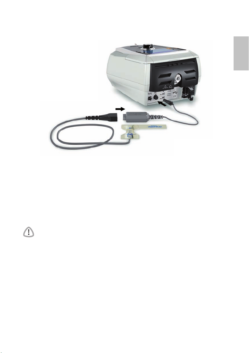
Attaching the pulse oximeter
1
2
Use of a pulse oximeter may be recommended by your clinician.
Contraindication
The pulse oximeter does not meet defibrillation-proof requirement per IEC 60601-1: 1990,
clause 17.h.
1 Connect the plug of the finger pulse sensor to the plug of the pulse oximeter.
2 Connect the plug of the pulse oximeter at the rear of the device.
To view the oximetry values, from the Monitoring menu, select Monitoring.
Adding supplemental oxygen
Oxygen may be prescribed by your clinician.
Note: Up to 30 L/min at maximum oxygen pressure of 50 mbar (0.73 psi) can be added.
WARNING
• Oxygen flow must be turned off when the device is not operating, so that unused
oxygen does not accumulate within the device and create a risk of fire.
• Use only certified, clean oxygen sources.
• ResMed strongly recommends adding oxygen into Stellar’s oxygen inlet at the
rear of th
a side port or at the mask, has potential to impair triggering and accuracy of
therapy/monitoring and alarms (eg, High Leak alarm, Non-vented mask alarm). If
used in this way, therapy and alarm operation must be verified each time oxygen
flow is adjusted.
• O
presence o
• The breathing system and the oxygen s
distance of 2 m away from any sources of ignition (eg, electrical devices).
•
Oxygen must not be used while the device is being operated within the mobility bag.
e device. Entraining oxygen elsewhere, ie into the breathing system via
xygen supports combustion. Oxygen must not be used while smoking or in the
f an open flame. Only use oxygen supply in well-ventilated rooms.
ource must be kept at a minimum
English
7Working with other optional accessories
Page 13

2
1
1
Press spring to release
connection after use
Starting therapy using oxygen
1 Fit the oxygen connector to the oxygen inlet of the device.
2 Attach the other end of the oxygen supply tubing to the oxygen supply.
3 Press to start treatment.
4 Turn on oxygen.
Stopping therapy using oxygen
1 Turn off oxygen.
2 Press to stop treatment.
Using the FiO2 monitoring sensor
Use of the FiO2 monitoring sensor may be recommended by your clinician.
CAUTION
Do not use the FiO2 monitoring sensor with the H4i humidifier.
Preparing to use a new sensor
1 Before use, leave the FiO
2 Attach a new FiO
2
3 Perform the sensor calibration (see “Setup menu” on page 16).
Note: The FiO
monitoring sensor must be replaced every 12 months.
2
monitoring sensor open to the air for 15 minutes.
2
monitoring sensor (as shown below).
Oxygen supply
2
3
5
1
2
8
4
Page 14

Connecting a sensor
1 Connect the air tubing to the T-piece adapter.
2 Connect the FiO
monitoring sensor to the T-piece adapter.
2
3 Connect the adapter to the air outlet of the device.
4 Connect one end of the cable to the FiO
monitoring sensor.
2
5 Connect the other end of the cable to the rear of the device.
6 Start calibration (see “Setup menu: Options” on page 16). This should be repeated
periodically at the recommendation of your clinician.
Attaching an antibacterial filter
The use of an antibacterial filter may be recommended by your clinician. One antibacterial
filter—product code 24966—can be purchased separately from ResMed.
Regularly check the filter for entry of moistu
replaced according to the manufacturer‘s specifications.
Note: ResMed recommends using a filter with a lo
60 L/min, eg, PALL BB 50 filter).
WARNING
Do not use the antibacterial filter (product code 24966) with the H4i.
re or other contaminants. The filter must be
w impedance (less than 2 cm H2O at
1
2
English
1 Fit the antibacterial filter to the air outlet of the device.
2 Attach the air tubing to the other side of the filter.
3 Attach the mask system to the free end of the air tubing.
4 Perform the Learn Circuit function (see “Setup menu: Options” on page 16). From the
Setup menu, select Options. This enables
introduced by the filters.
the device to compensate for the impedance
9Working with other optional accessories
Page 15

Stellar basics
About the control panel
Mains Power LED
On when operating on mains power.
External power supply
LED
On when external battery is
connected.
Internal battery LED
On when internal battery is in
use. Flashes when device is
turned off and battery is
charging.
LCD Screen
Monitoring menu
Setup menu
Alarm LED
Red or yellow during an
alarm or during alarm
testing.
Alarm mute button LED
On when is pressed.
Start/stop button
Key Function
Start/Stop • Starts or stops treatment.
Alarm mute • During therapy: Press once to mute an alarm. Press a
Menu keys Press the appropriate menu button (Monitoring, Setup, Info)
Info menu
(rotate/
arts the
• Extended hold for at least three seco
Push dial
click)
Therapy LED
On during treatment.
Flashes during maskfitting operation.
nds st
maskfitting feature.
second time to un-m
ute an alarm. If the problem is still
present, the alarm will sound again after two minutes.
See “Working with alarms” on page
13.
• In stand-by mode: Extended hold for at least three
seconds st
to enter and
the alarm LED and alarm buzzer test.
arts
scroll through the relevant menu.
10
Push dial Turning the dial allows you to scroll throug
change settings. Pushing the dial allows you to enter into a
menu or confirm your choice.
h the m
enu and
Page 16

LCD screen
The LCD screen displays the menus, monitoring screens and alarm status.
Warm-up feature H4i
ResMed USB stick
Mains power
External power supply
Internal battery
Title bar
Settings
Therapy status bar
Ramp time
Program
Therapy mode
Patient mode or
Clinical mode
Current screen/number of
screens within the menu
Scroll bar
Starting therapy
Performing a functional test
Make sure your device is functioning properly each time before starting therapy.
If any problems occur, see “Troubleshooting” on page 21. Please also check other
provided User Instructions for troubleshooting information.
1 Turn off the device by pressing the power switch at the back of the device.
2 Check condition of device and accessories.
Inspect the device and all the provided accessories. If there are any visible defects, the
system should
3 Check the circuit configuration.
Check the integrity of the circuit configuration (dev
to the setup descriptions in this User Guide and that all connections are secure.
4 Turn on the device and check alarms.
Press the power switch at the back of the device once to turn on the device.
Check that the alarm sounds a test beep and the LEDs (visual indicator) for the alarm
and the Alarm mute button flash. The device is ready for use when the Treatment screen
is displayed. If the display shows the Reminder page, follow the instructions, then press
to display the Tr
5 Check batteries.
Disconnect the device from the mains and external
powered by the internal battery. Check that the Battery use alarm is displayed and the
battery LED is on.
Note: If the charge state of the internal battery is too lo
alarm occurs. See the Alarm troubleshooting section on page 21 for further information.
Reconnect the external battery (if in use) and check that the LED for the external power
supply is lit. The External DC power use alarm will be displayed and the Alarm LED will light.
Reconnect the device to the mains.
6 Check H4i heated humidifier (if in use).
Check that the warm-up feature is displayed in the Tr
feature. Check that the humidifier warm-up symbol is displayed on top of the screen.
not be used.
ice and provided accessories) according
eatment screen.
battery (if in use) so that the device is
w, or if the battery is empty, an
eatment screen. Start the warm-up
English
signal
11Starting therapy
Page 17

Warm-up humidifier
You can use the warm-up feature to pre-heat
the water in the humidifier prior to starting
treatment. The humidifier will be
detected when the device is turned on. The
Treatment screen provides the option to start
warming the humidifier. If the humidifier is
heating, the related symbol is displayed at the
top of the LCD screen.
For more information, see the H4i User Guide.
Note:
The H4i in heating mode can only be used
when the device is connected to mains supply.
automatically
7 Check the FiO
Start the FiO
Options” on page 16). Follow the instructions on the display.
monitoring sensor (if in use).
2
sensor calibration. Select Setup menu, then Options (see “Setup menu:
2
8 Check pulse oximeter (if in use).
Attach the accessories according to the setup
oximeter” on page 7). From the Monitoring menu page g
that the values for SpO
and Heart rate are displayed.
2
descriptions (see “Attaching the pulse
o to the Monitoring screen. Check
9 Check oxygen connection (if in use).
Attach the accessories according to the setup
oxygen” on page 7).
descriptions (see “Adding supplemental
Starting therapy
CAUTION
The Clinical mode is only for clinicians. If the device is operating in clinical mode
press the power switch to re-start the device in patient mode
.
1 Fit your patient interface (mask or catheter mount) as described in the user instructions.
2 Lie down and arrange the air tubing so that it is free to move if you turn in your sleep or
arrange the tubing so it is comfortable in your wheelchair.
3 To start treatment, press or if the SmartStart/Stop function is enabled, simply breathe
into your patient interface and treatment will begin.
Stopping therapy
You can stop therapy at any time, simply remove the patient interface and press to stop
airflow or if SmartStart/Stop is enabled, simply remove the patient interf
will stop automatically.
Notes:
• SmartStop may not work if Full face or Tr a c h is selected as mask type; the High Leak
alarm o
r
the Low Min Vent alarm is enabled; “Confirm Therapy Stop“ is enabled; or the
mask-fitting feature is running.
• When the device is stopped and operating in standby mode with an inte
humidifier connected, it will continue to blow air gently to assist cooling of the
humidifier’s heater plate.
• Masks with high resistance (eg, paediatric masks) may cause the operation of the
Sm
artStop feature to be restricted.
• When using with oxygen, turn off oxygen flow before stopping therapy.
ace, and treatment
grated
12
Page 18

Turning off the power
1 Stop the therapy.
2 Press the power switch at the back of the device once and follow the instructions on
the display.
Note: T
o disconnect the device from the mains po
power socket.
wer pull out the power cord from the
Working with alarms
WARNING
This device is not intended to be used for vital signs monitoring. If vital signs
monitoring is required, a dedicated device should be used for this purpose.
This device is fitted with alarms
Alarm LED
Alarm mute key
Alarm messages are displayed along the top of the screen. High priority alarm
displayed in red, medium priority alarms in yellow and low priority alarms in light blue. The
Alarm LED lights red during high priority alarms and yellow during medium and low priority
alarms.
The alarm volume can be set Low, Medium or High. From
Settings. After the set value has been confirmed, the alarm will sound and the alarm LED
lights.
Alarm settings, see “Setup menu: Alarm Settings (Alarm Volume
You can mute an alarm by pressing once. By pressing the Alarm mute key again, the
alarm sounds again. When an alarm is muted, the Alarm
For a high or medium priority alarm, if after two minutes the problem is still present, the
alarm will sound again. Any active low priority alarm will be permanently muted and the
Internal Battery Use alarm will be cleared until the alarm condition is fulfilled again.
to alert you to changes that will affect your treatment.
Alarm message
s are
the Setup menu, select Alarm
)” on page 16.
mute key LED will light constantly.
English
13Starting therapy
Page 19

Tailoring treatment setup options
Setting Ramp
Ramp time
Ramp time is a feature that can be enabled
by your clinician by sett
time. Designed to make the beginning of
treatment more comfortable, ramp time is
the period during which the pressure
increases from a low start pressure to the
treatment pressure. See “Setup menu:
Options” on page 16.
ing a maximum ramp
Programs
Program
If the Clinician has selected both, ie, dual,
you can choose the program to use on the
eatment screen. If only a single program is
Tr
selected, the option does not display.
Using mask-fit
You can use mask-fit to help you fit your mask properly. This feature delivers constant
treatment pressure for a three-minute period, prior to starting treatment, during which you
can check and adjust your mask-fit to minimise leaks. The mask-fit pressure is the set
CPAP or EPAP pressure or 10 cm H
1 Put the mask on according to the mask user guide.
2 Hold down for at least three seconds until pressure delivery starts.
3
If necessary adjust the mask, mask cushion and headgear until you have a good mask fit.
After three minutes treatment will begin. Mask-fit can be stopped at any time by pressing .
Notes:
• Press for at least three seconds during mask-fit to start the treatment imm
• The mask-fitting feature is di
O, whichever is greater.
2
sabled when the mask type Tr a c h is selected.
ediately.
14
Page 20

Using the menus
The device has three menus (Monitoring, Setup, Info) accessed by the equivalent buttons
on the right of the LCD screen. In each menu there are screens that display settings, device
or therapy information.
MONITORING
Treatment
Monitoring
Pressure / Flow
Min Vent/Resp Rate
or MV/Va (iVAPS
Mode)
Leak
Tidal Volume
Synchronisation
Oximetry
SETUP
Clinical Settings
Alarm Settings
Options
INFO
Event Summary
Leak
Minute Ventilation
Tidal Volume
Respiratory Rate
I:E Ratio
Pressure Support
AHI
English
Note: iVAPS mode is only available in Stellar 150.
SpO
2
Used Hours
Device Information
Reminder
15Using the menus
Page 21

Page 22

Parameter Description
Learn Circuit The device is calibrated according to y
1. If in use, turn off the oxygen flow.
2. Select the mask type.
3. Set up the air circuit including access
Note: For invasive use, do not connect a catheter mount,
tracheostomy tub
on page 5).
4. Leave the air circuit unobstr
5. Press to start the Learn Circuit.
6. Wait for the device to complete its automated tests (<30 sec).
The results are displayed when complete. If the circuit
configuration has been successfully learn
unsuccessful, displays (see “Troubleshooting” on page 21).
Sensor
FiO
2
Calibration
R
amp Time If Max Ramp Time has been set by the
The device starts the calibration of the FiO2 monitoring sensor to
measure the oxygen concentration of the breathable air.
1. Press to start the FiO
2. Wait for the device to complete its calibration. The results are displayed when complete.
urn off the oxygen flow.
Note: T
value up to this time.
Options: 0 min-Max Ramp Time (max 45 minutes, 5 minutes
increm
ents)
Setup menu: Configuration Menu
Parameter Description
Language Sets the display language.
Brightness Sets the LCD backlight bright
Backlight Enables the LCD and keypad backlight.
Time format Sets the time format.
Date format Sets the date format.
To return to the Options screen press the Return button
Options: Depending on regional configuration
Options: 20-100%, 10% increments
If the AUTO setting is selected the backlight turns dark after five
minutes wi
pressed again or an alarm occurs.
Options: On, Auto
Options: 24 hrs,12 hrs
Options: dd/mm/yyyy, mm/dd/yyyy
thout any actions and turns on again if any button is
our air tubing system.
ories and patient interface.
e or HMEF, see “Setting up for invasive use”
ucted and open to the
t
sensor calibration.
2
clinician, you may select any
ness.
air.
, displays. If
English
17Setup menu
Page 23

Info menu
Event Summary
Used Hours
Device Information
Event summary displays the summary of three
types of events: changes in se
system events (eg, connection of ResMed USB
stick). There are up to 200 events of each type,
displayed in chronological order, with the most
recent event displayed at the top by default.
Used Hours during the last seven days of
treatment are displayed in a bar gr
compared to the data of the last 365 days.
This screen shows the serial number (displayed
as Device SN), software version and other
component versions. Data on th
requested for servicing or as part of problemsolving by a technician.
ttings, alarms and
aph and can be
is screen may be
18
Reminders
The Clinician uses the Reminders menu to alert
you to specific events; for example
replace the mask, when to replace the filter and
so on. The reminder appears in yellow as the date
approaches (within 10% of the reminder period).
The reminder also displays on the startup screen.
You can clear a reminder message by selecting
‘Reset’, which clears the current reminder date
to OFF, or displays the next pre-set Reminder
date.
, when to
Page 24

Data management
There are two data ports at the rear of the device for connecting a USB stick (see “Stellar
at a glance” on page 2). Therapy and device data can be stored on it or read from it to be
used with ResMed software applications.
WARNING
Do not connect any device to the data ports other than specially designed devices
recommended by ResMed. Connection of other devices could result in injury, or
damage to the Stellar (see “General warnings and cautions” on page 30).
CAUTION
Do not disconnect the ResMed USB stick while data transfer is in progress. Otherwise
loss of data or incorrect data may result. The download time depends on the data
volume.
Notes:
• You cannot connect two ResMed USB sticks simultaneou
• If data transfer is not possible or failed please read the troubleshooting
• Do not store files on the USB stick other th
application. Unknown files may be lost during data transfer.
an those created by the device or
1 Plug the ResMed USB stick to one of the two USB connections on the rear side of the
device.
The first dialogue for the USB data transfer is displayed automatically on the LCD. The device
checks if there is enough memory capacity on the USB stick and if readable data is available.
2 Select one of the available options
• Read sett
The settings will be transfered from the connected ResMed U
• Write settings
Se
• Write settings and loggings
Se
• Cancel
ings
ttings of the device will be stored on the ResMed U
ttings and loggings of the device will be stored on the ResMed USB stick.
3 Confirm the data transfer.
sly for data communication.
section.
SB stick to the Stellar.
SB stick.
English
Cleaning and maintenance
The cleaning and maintenance described in this section should be carried out regularly.
This also helps to prevent the risk of cross contamination. Refer to the mask, humidifier
and other accessories user guide for detailed instructions for care and maintenance.
WARNING
• Beware of electric shock. Do not immerse the device, pulse oximeter or power
cord in water. Turn off the device, unplug the power cord from the power socket
and the device before cleaning and be sure that it is dry before reconnecting.
• The mask system and air tubing are subject to normal wear and tear. Inspect
them regularly for damage.
CAUTION
The device cannot be sterilised.
Daily
Disconnect the air tubing from the device (and humidifier, if used) and hang it in a clean,
dry place until next use.
CAUTION
Do not hang the air tubing in direct sunlight as the tubing may harden over time and
eventually crack.
19Data management
Page 25

Weekly
1 Remove the air tubing from the device and the patient interface.
2 Wash the air tubing in warm water using mild detergent.
3 Rinse thoroughly, hang and allow to dry.
4 Reconnect the air tubing to the air outlet and patient interface.
CAUTION
Do not use bleach, chlorine, alcohol or aromatic-based solutions (including all
scented oils), moisturising or antibacterial soaps to clean the air tubing or the device.
These solutions may cause hardening and reduce the life of the product.
Monthly
1 Wipe the exterior of the device and the pulse oximeter (if used) with a damp cloth and mild
detergent.
2 Check the air filter to check if it is blocked by dirt or contains holes.
Replacing the air filter
Replace the air filter every six months (or more often if necessary).
WARNING
Do not wash the air filter. The air filter is not washable or reusable
1 Remove the air filter cover from the back of the device.
2 Remove and discard the old air filter.
3 Insert a new air filter.
4 Refit the air filter cover.
.
20
Air filter
Air filter cover
Disinfection
Disinfection of your device helps to prevent the risk of cross contamination.
Disinfect the exterior of the device, and especially the air outlet, with a damp cloth an
disinfection solution (eg, Microzid).
d a
Page 26

Multipatient use
WARNING
An antibacterial filter is mandatory if the device is used on multiple patients.
In a mulitpatient use environment, you must perform the following befo
provided to a new patient:
Air filter and the
antiba
cterial filter
Mask
Air tubing Replace the air tubing. Alternatively, consult the air tubing
Device Disinfect the Stellar as follows:
Humidifier As instructions for humidifiers va
Replace.
Reprocess; Cleaning, disinfection and sterilisation
instructions are available from the ResMed website,
www.resmed.com/masks/sterilization. If you do not have
Internet access, please contact your ResMed representative.
instructions for cleaning and disinfection information.
1. Apply undiluted mikrozid
clean non-dyed disposable cloth.
2. Wipe all surfaces of the device, including the
avoid liquid entering any openings in the device.
3. Leave the disinfectant to work for five minutes.
4. Wipe residual disinfectant from the de
dry non-dyed disposable cloth.
the humidifier in use.
®
AF or CaviCide® liquid to a
ry, see the user guide for
re the device is
vice w
Servicing
CAUTION
Inspection and repair should only be performed by an authorised agent. Under no
circumstances should you attempt to open, service or repair the device yourself.
This product should be inspected by an authorised Re
the date of manufacture, except for the internal battery which must be replaced every two
years from the manufacturing date of the device. Prior to this, the device is intended to
provide safe and reliable operation provided that it is operated and maintained in
accordance with the instructions provided by ResMed. Applicable ResMed warranty
details are provided with the device at the time of original supply. Of course, as with all
electrical devices, if any irregularity becomes apparent, you should exercise caution and
have the device inspected by an authorised ResMed service centre.
sMed service centre five years from
air outle
ith a clean,
t;
English
Troubleshooting
If there is a problem, try the following suggestions. If a problem cannot be solved, contact
ResMed.
Alarm troubleshooting
The most common reason for an alarm to sound is because the system has not been
properly assembled. Check that the air tubing has been properly attached to the device and
patient interface (and humidifier if used).
Notes:
• The alarm log and alarm settings are m
in the event of a power loss.
• If multiple alarms are active simultaneously, the alarm with the h
displayed first.
• If an alarm activates repeatedly, discontinue use and return the device for servicin
aintained when the device is powered down and
ighest priority will be
g.
21Troubleshooting
Page 27

Problem / possible cause Action
LCD: Internal Battery Empty!
The remaining battery charge is below
The device can be powered by the
15%.
internal battery for maximum 2 minutes.
Connect the device to mains power.
Note:
In case of a total power failure, the
therapy settings will be stored and therapy
will resume when the device is powered
again.
LCD: System Failure!
Component failure.
The device stops delivering air pressure
(sys
tem failure 6, 7, 9, 22, 38). Therapy
1. Power-off the device.
2. Power-on the device again.
cannot be started (system failure 21). Component failure (system failure 8, 25). 1. Power-off the device.
2. Power-on the device again.
LCD: Over Pressure!
The device generates a pressure
greater than 60 cm H
be stopped.
O. Treatment will
2
that is
1. Power-off the device.
2. Check that the air tubing is connected
properly.
Power-on the device again.
3.
4. Start Learn Circuit function.
Note: If the alarm activates repeatedly
internal components may be defective.
Discontinue use and return the device for
servicing.
LCD: Blocked Tube!
Air path is blocked. 1. Check the air path for any blockages.
2. Remove the blockages.
3. If the alarm is n
ot cleared
, stop
treatment.
4. Re-start treatment.
LCD: High Temperature [10, 11, 12, 13]!
The temperature inside the device is too
. T
reatment may lead to stop.
high
Ensure the ambient temperature is within
the specified operating range. If the
problem persists within the specified
operating conditions please return the
device for servicing.
Contact your clinician.
LCD: High Pressure!
Therapy pressure exceeds pre-set alarm
lev
el.
1. Stop treatment.
2. Re-start treatment. If the problem persists cont
act y
our
clinician.
LCD: Low Pressure!
The air tubing is not connected properly. 1. Check the air circuit integrity and
nnect.
reco
2.
If the alarm doesn‘t get cleared, stop
treatment.
Re-start treatment.
3.
22
Page 28

Problem / possible cause Action
LCD: Circuit disconnected!
The air tubing is not connected properly
to the humidifier or the device.
. Check that the air tubing is connected
1
properly to the humidifier or the
device.
2. If the alarm is n
treatment.
3. Re-start treatment.
LCD: Low Minute Ventilation!
Minute ventilation level has dropped
w
the alarm setting level.
belo
Contact your clinician.
LCD: Low Respiratory Rate!, High Respiratory Rate!
The respiratory rate level has dropped
or has exceeded the alarm setting
below
Contact your clinician.
level.
LCD: High Leak!
High mask leak for more than 20
seconds.
• Adjust the mask to minimise leak (see
“Using mask-fit” on page 14).
• Check the air circuit integrity and
reconnect.
• If the p
roblem persists c
clinician.
LCD: Non-Vented Mask!
• Connection of a non-vented mask.
• Mask vents may be blocked.
• ResMed leak port is missing or vent
blocked.
• Ensure the mask has vents.
• Ensure the mask vents are not
block
ed.
is
• Ensure the leak port is installed and
that the ve
nt is not blocked.
• Ensure oxygen (if in use) has only been
connected at the rear of the de
• If the problem persists c
clinician.
LCD: Apnoea!
The device detects an apnoea that has
ex
ceeded the pre-set alarm level.
• Breathe normally to disable the alarm.
• If the problem persists c
clinician.
LCD: Internal Battery Low!
The internal battery capacity is below
Connect the device to mains power.
30%.
LCD: Low SpO
has dropped below pre-set alarm
SpO
2
level.
!
2
• Check the attachment of the sensor.
• If the problem persists c
clinician.
LCD: SpO
The finger sensor is not connected
properly or delivers f
finger sensor failure!
2
aulty values.
Check if the finger sensor is attached
properly to the finger and connection to
the pulse oximeter.
LCD: Xpod oximeter disconnected!
The pulse oximeter is disconnected.
Check if the pulse oximeter is connected
properly to the device.
ot cleared
, stop
ontact your
vice.
ontact your
ontact your
ontact your
English
23Troubleshooting
Page 29

Problem / possible cause Action
LCD: Low FiO2 Level!
has dropped below the pre-set
FiO
2
alarm level.
• Perform FiO
• If the problem persists cont
sensor calibration.
2
act your
clinician.
LCD: High FiO
has exceeded the pre-set alarm
FiO
2
level.
Level!
2
• Perform FiO
• If the problem persists cont
sensor calibration.
2
act your
clinician.
LCD: Keypad Failure!
One of the keys was held down for more
than 1
0 seconds
or got stuck.
Remove any blockages from the keypad.
LCD: Attention High Temp [42, 43, 44, 45]!
The temperature inside the device is
high.
En
sure the ambient temperature
conditions are within the specified
operating range.
LCD: Internal Battery Use!
The device is using the internal battery. Check if the power cord is properly
vice if y
connected to the de
ou want to
run from mains power.
Press the Alarm mute button to cancel
the alarm.
LCD: External DC Power Use!
The device is powered by an external
batt
ery.
Check if the AC power cord is properly
connected to the device if you want to
run from mains power.
Note: The alarm will be cleared
automa
tically after one minute.
24
Other troubleshooting
Problem / possible cause Solution
No display
Power failure. The device stops delivering
air pressure.
Power not connected or device is not
switc
hed on.
Treatment pressure seems low
Ramp time is in use. Wait for air pressure to build up.
Air filter is dirty. Replace air filter.
Air tubing is kinked or punctured. Straighten or replace tubing.
Air tubing is not connected properly. Connect the air tubing firmly at both
Mask and headgear not positioned
ectly.
r
cor
Plug(s) missing from access port(s) on
.
mask
Remove the mask or the catheter mount
from the trache
ostomy tube until power
is restored.
Ensure the power cord is connected and
press the switch at the back of the device
once.
ends.
Adjust position of mask and headgear.
Replace plug(s).
Page 30

Problem / possible cause Solution
Pressure required for treatment may
have changed.
There is a large impedance (eg,
antibacterial filter) in the air circuit.
Humidifier control dial set too high,
lting in accumulation of water in the
resu
air tubing.
Treatment pressure seems high
Pressure required for treatment may
v
e changed.
ha
There is a change in the impedance in the
circuit configurations.
The device does not start when y
SmartStart/Stop not on. Consult your clinician.
Breath is not deep enough to trigger
tStart.
Smar
There is excessive leak. Adjust position of mask and headgear.
Plug(s) missing from port(s) on mask. Replace plug(s).
Air tubing is not connected properly. Connect firmly at both ends.
Air tubing is kinked or punctured. Straighten or replace tubing.
There is a large impedance (eg,
antibacterial filter) in the air circuit.
The device does not stop when you remove your mask
SmartStart/Stop is disabled. Consult your clinician.
Use of a full face mask or tracheostomy
ube.
t
Incompatible accessories (eg, humidifier
sk system) with high resistance
or ma
being used.
High Leak Alarm or Low Min Vent alarms
are se
t to ON.
“Confirm Stop” is enabled. Consult y
High Leak Alarm is enabled, but alarm does not activate when the mask
is remo
Incompatible air delivery system being
used
Pressure settings are too low f
delivery components being used.
Learn Circuit failed
• The circuit configuration is
• Too many components have been
ved during treatment
.
or the air
opriate as the impedance
inappr
detected is too high.
included or the impedan
accessories in use is above ResMed’s
recommendation, eg, type of filter,
external humidifier, air tubing.
ce of
See your clinician to adjust the pressure.
Perfom the Learn circuit function.
Turn humidifier control down and empty
the water from the air tubing.
Consult your clinician.
Perform the Learn Circuit function.
ou breathe into the mask
Take a deep breath in and out through the
mask.
Perform the Learn circuit function.
artStart is disabled if Full face mask or
Sm
Trach is selected as interface.
Use only equipment as recommended
and su
pplied by ResMed.
Consult your clinician.
our clinician.
Use only e
and supplied by ResMed.
Perform the Learn circuit function to
adjust the therapy pressure according to
your air tubing system.
Review the components included in the
circuit configuration and adjust as
appropriate,
“Setup menu” on page 16
quipment as recommended
un Learn Circuit (see
then rer
).
English
25Troubleshooting
Page 31

Problem / possible cause Solution
The delivered airflow is not humid/heated although the H4i humidifier is
in use
t
The humidifier is not properly at
ached. Correctly attach the humidifier.
The humidifier does not heat. The device is currently powered by
ery use or not connected to the
batt
mains.
The humidifier does not work. Return the device and the humidifier for
icing.
serv
The water chamber is empty. Fill the water chamber of the humidifier.
USB stick is not readable or writeable
The USB stick contains unreadable data,
does not hav
e enough space available, is
Consult your clinician.
not compatible with the device.
USB stick is defective. Replace the USB stick after consulting
y
our clinician.
sensor calibration failure
Fi
O
2
sensor is not attached properly. For the correct attachment of the FiO2
FiO
2
sensor, see “Using the FiO2 monitoring
sensor” on page 8.
FiO
sensor is used or defective. If the lifetime of the FiO2 sensor has
2
exceeded one year please replace the
FiO
sensor and start calibration again.
2
LCD: is displayed in the header
Battery is not charging.
•
Ensure the ambient temperature
conditions are within the specified
operating range. If the problem persists
within the specified operating conditions
please return the device for servicing.
• Power-off the device. Power-on the
device again.
26
Technical specifications
Operating pressure
ra
ge
n
Maximum single fault
essure
pr
Breathing resistance
under s
ingle fault
Maximum flow > 200 L/min at 20 cm H
Flow accuracy ± 6 L/min or 20% measured value, whichever is greater
• IPAP: 2 cm H
• PS: 0 cm H
• EPAP: 2 cm H
• CPAP: 4 cm H
• Min PS: 0 cm H
• Max PS: 0 cm H
Note: iVAPS mode is only available in Stellar 150.
60 cm H2O (in all modes)
2 cm H2O at 30 L/min;
7. 2 c m H
Test condition: T mode, IPAP: 40 cm H
2 cm H
Respiratory Rate: 10 bpm, with ResMed calibration cap.
O to 40 cm H2O (in S, ST, T, PAC mode)
2
O to 38 cm H2O (in S, ST, T, PAC mode)
2
O to 25 cm H2O (in S, ST, T, iVAPS, PAC
mode)
2
2
O to 20 cm H2O (in CPAP mode only)
2
O to 20 cm H2O (in iVAPS mode)
2
O to 30 cm H2O (in iVAPS mode)
2
O at 60 L/min
2
O
2
O, EPAP:
O, Rise Time: MIN, Fall Time: MIN, Ti: 4.0 sec,
2
Page 32

Therapy pressure
tolerance
IPAP: ± 0.5 cm H2O ± 10% of set pressure (end of
inspiration)
EPAP/PEEP: ± 0.5 cm H
CPAP: ± 0.5 cm H
Test condition: T mode, IPAP: 40 cm H
O, Rise Time: MIN, Fall Time: MIN, Ti: 4.0 sec,
H
2
Respiratory Rate: 10 bpm, with ResMed calibration cap.
O ± 4% of set pressure
2
O ± 10% of set pressure
2
O, EPAP: 2 cm
2
Sound pressure level 29 dBA as measured according to ISO 17510 – 1:2002.
32 dBA with uncertainty of 3 dBA as measured according
Alarm Volume Range
to ISO 1751
> 45 dBA - < 85 dBA at 1 meter (3 steps: low, medium, high)
0 – 1:2007.
Dimensions (L x W x H) 230 mm x 170 mm x 120 mm
Weight 2.1 kg
Air outlet 22 mm taper, compatible with ISO 5356-1:2004
Anaesthetic & Re
spiratory Equipment - Conical
Connectors
Pressure measurement Internally mounted pressure transducer
Flow measurement Internally mounted flow transducer
Power supply AC 100–240V, 50–60Hz, 2.2 A, max. 65 W
External DC Power
24 V, 3 A
Supply
Internal Battery Lithium-Ion battery, 14.4 V, 1.6 Ah, 23 Wh
Operating hours: 2 h with a new battery under normal
conditions (see belo
w).
Patient type: home chronic; pressure: IPAP/EPAP 15/5
cm H
O; mask type: Ultra Mirage; air tubing: 2 m; leak:
2
0; respiratory rate: 20 bpm; battery capacity: 100%
Patient type: hospital acute; pressure: IPAP/EPAP 20/5
cm H
O; mask type: Ultra Mirage; air tubing: 2 m; leak:
2
0; respiratory rate: 45 bpm; battery capacity: 100%
Housing construction Flame retardant engineering thermoplastic
vironmental
En
condition
s
• Operating temperature: 0°C to 35°C
• Operating humidity: 10%–95% non-condensing
• Storage and transport temperature: -20°C to 60°C
(+50°C*)
• Storage and transport humidity: 10%–95% non-
cond
ensing
ir pressure: 1,100hPa to 680hPa; Altitude: 3,500 m
• A
*NONIN XPOD
Electromagnetic
compatibility
P
roduct complies with all applicable electromagnetic
compatibility requirements (EMC) according to
IEC60601-1-2, for residential, commercial, and
light
industry environments. For further details see “Guidance
and manufacturer’s declaration – elec
tromagnetic
emissions and immunity” on page 28.
Air filter
Electro static fibre mesh with TPE frame structure. Bacterial
filtration efficiency of 99.540% on area weight 100g/m².
Air tubing Flexible plastic, 2 m or 3 m length (22 mm diameter)
SlimLine air tubing
Flexible plastic, 1.83 m length (15 mm diameter)
English
27Technical specifications
Page 33

IEC 60601-1
classif
ications
• Class II (Clause 3.14—double insulation). This
adherence means the need for an protective earthing
(ie, an earthed plug) is not necessary.
• Type BF
• Continuous operation
Air travel requirements Medical-Portable Electronic Devices (M-PED) that meet
the Federal A
viation Administration (FAA) requirements
of RTCA/DO-160 can be used during all phases of air
travel without further testing or approval by the airline
operator. ResMed confirms that the Stellar meets RTCA/
DO-160 requirements.
This device is not suitable for use in the p
esence of a flammable anesthetic mixture.
r
Notes:
• The manufacturer reserves the right to change these specification
• Pressure may be displayed in cm H
O or hPa.
2
s without notice.
Guidance and manufacturer’s declaration – electromagnetic emissions and immunity
Medical Electrical Equipment needs special precautions regarding EMC and needs to be
installed and put into service according to EMC information provided in this document.
Guidance and manufacturer’s declaration – electromagnetic emissions
The device is intended for use in the electromagnetic environment specified below. The customer or the user of the device should assure that it is used in such an environment.
Emissions test Compliance Electromagnetic environment - guidance
RF emissions CISPR11 Group 1 The device uses RF energy only for its internal function.
RF emissions CISPR 11 Class B The device is suitable for use in all establishments,
Harmonic Emissions
IEC 61000-3-2
Voltage Fluctuations/Flicker Emissions IEC 61000-3-3
Warnings: The device should not be used adjacent to or stacked with other equipment.
If adjacent or stacked use is necessary, the device should be observed to verify normal operation in the
configuration in which it will be used.
The use of accessories (eg, humidifiers) other than those specified in this manual is not recommended. They may
result in increased emissions or decreased immunity of the device.
Class A
Complies
Therefore, its RF emissions are very low and are not
likely to cause any interference in nearby electronic
equipment.
including domestic establishments and those directly
connected to the public low-voltage network that
supplies buildings used for domestic purposes.
28
Guidance and manufacturer’s declaration – electromagnetic immunity
The device is intended for use in the electromagnetic environment specified below. The customer or the user of the
vice should assure that it is used in such an environment.
de
Immunity test
Electrostatic discharge (ESD) IEC 61000-4-2
Electrical fast
transient/burst
IEC 61000-4-4
Surge IEC 61000-4-5
IEC606 01-1-2 tes t
lev
el
±6 kV contact ±8 kV air
±2 kV for power supply lines
±1 kV for input/output lines
±1 kV differential mode
±2 kV common mode
Compliance level Electromagnetic environment –guidance
±6 kV contact ±8 kV air
±2 kV
±1 kV
±1 kV differential mode
±2 kV common mode
Floors should be wood, concrete or ceramic tile. If floors are covered with synthetic material, the relative humidity should be at least 30%.
Mains power quality should be that of a typical commercial or hospital environment.
Mains power quality should be that of a typical commercial or hospital environment.
Page 34

Voltage dips,
short
interruptions
and voltage
variations on
power supply
input lines
IEC 61000-4-11
Powe r
frequency
(50/60 Hz)
magnetic field
IEC 61000-4-8
Conducted RF IEC 61000-4-6
Radiated RF IEC 61000-4-3
NOTE 1: Ut is the AC mains voltage prior to application of the test level.
NOTE 2: At 80 MHz and 800 MHz, the higher frequency range applies.
NOTE 3: These guidelines may not apply in all situations. Electromagnetic propagation is affected by absorption and reflection
om structures, objects and people.
fr
a
Field strengths from fixed transmitters, such as base stations for radio (cellular/cordless) telephones and land mobile radios,
amateur radio, AM and FM radio broadcast and TV broadcast cannot be predicted theoretically with accuracy. To assess the
electromagnetic environment due to fixed RF transmitters, an electromagnetic site survey should be considered. If the
measured field strength in the location in which the device is used exceeds the applicable RF compliance level above, the device
should be observed to verify normal operation. If abnormal performance is observed, additional measures may be necessary,
such as reorienting or relocating the device.
b
Over the frequency range 150 kHz to 80 MHz, field strengths should be less than 10 V/m.
<5% Ut (>95% dip in Ut) for 0.5 cycle
40% Ut (60% dip in Ut) for 5 cycles
70% Ut (30% dip in Ut) for 25 cycles
<5% Ut (>95% dip in Ut) for 5 sec
3 A/m 3 A/m Power frequency magnetic fields should be at
3 Vrms 150 kHz to 80 MHz
10 V /m 80 MHz to 2.5 GHz
< 12 V (>95% dip in 240V) for 0.5 cycle
96 V (60% dip in 240 V) for 5 cycles
168 V (30% dip in 240 V) for 25 cycles
<12 V (>95% dip in 240 V) for 5 sec
3 Vrms
3 V/m
Mains power quality should be that of a typical
commercial or hospital environment.
If the user of the device requires continued
operation during power mains interruptions, it is
recommended that the device be powered from
an uninterruptible power source.
levels characteristic of a typical location in a
typical commercial or hospital environment.
Portable and mobile RF communications
equipment should be used no closer to any part
of the device, including cables, than the
recommended separation distance calculated
from the equation applicable to the frequency of
the transmitter.
Recommended separation distance:
d = 1.17 √P
d = 0.35 √P 80 MHz to 800 MHz
d = 0.70 √P 800 MHz to 2.5 GHz
where P is the maximum output power rating of
the transmitter in watts (W) according to the
transmitter manufacturer and d is the
recommended separation distance in metres (m).
Field strengths from fixed RF transmitters, as
determined by an electromagnetic site survey,a
should be less than the compliance level in each
frequency range.b
Interference may occur in the vicinity of
equipment marked with the following symbol:
English
Recommended separation distances between portable and mobile RF communications equipment and the
device
The device is intended for use in an environment in which radiated RF disturbances are controlled. The customer or
the us
er of the device can help prevent electromagnetic interference by maintaining a minimum distance between
portable and mobile RF communications equipment (transmitters) and the device as recommended below, according
to the maximum output power of the communications equipment.
Separation distance according to frequency of transmitter (m)
Rated maximum output power of transmitter (W)
150 kHz to 80 MHz d = 1.17 √P
80 MHz to 800 MHz d = 0.35 √P
800 MHz to 2.5 GHz d = 0.7 √P
0.01 0.17 0.04 0.07
0.1 0.37 0.11 0.22
1 1. 17 0.35 0.7
29Technical specifications
Page 35

10 3.69 1. 11 2.21
F
100 11.7 0 3.50 7. 0
For transmitters rated at a maximum output power not listed above, the recommended separation distance d in
metres (m) can be determined using the equation applicable to the frequency of the transmitter, where P is the
maximum output power rating of the transmitter in watts (W) according to the transmitter manufacturer.
NOTE 1: At 80 MHz and 800 MHz, the separation distance for the higher frequency range applies.
NOTE 2: These guidelines may not apply in all situations. Electromagnetic propagation is affected by absorption and
reflection from structures, objects and people.
Symbols
Follow instructions for use; Class II equipment; Type BF equipment;
IP31 Device is protected against solid foreign objects of 2.5 mm diameter and greater and
vertically falling water drops; Caution; Standby or preparatory state for a part of
equipment; Connection for oxygen supply;
port; CE labeling in accordance with EC directive
+ 60 °C
+ 140 °
- 20 °C
Temperature limitation for storage and transport; Handle with care; Maximum
- 4 °F
max 30 l/min
(max 30 L/min); Data
93/42/EEC, class II b;
humidity; Keep dry; Manufacturer; Upside; Catalogue number;
Serial number;
away from sunlight; Do not use if package is damaged;
Batch code; Do not re-use; Use by date; Keep
LATEX
Latex-free
Environmental information This device must be disposed of in accordance with the laws
and regulations of the country in which disposal occurs.
The crossed-out wheeled bin symbol indicates that the product bearing this symbol
may not b
e disposed of together with general househo
ld waste, but instead requires
separate disposal. This requirement for separate disposal is based on the European
Directive 2002/96/EC for electrical and electronic equipment, and the European Directive
2006/66/EC for batteries. You can hand in the product at a municipal collection point, for
example. This reduces the impact on natural resources and prevents contamination of the
environment through the release of hazardous substances.
Batteries containing more than 0.0005 percent of mercury b
mass, more than 0.002
y
percent of cadmium by mass or more than 0.004 percent of lead by mass are marked
below the crossed-bin symbol with the chemical symbols (Hg, Cd, Pb) of the metals for
which the limit is exceeded.
For further information regarding product disposal, pl
ease contact your local ResMed office
or your specialist distributor, or visit our website at www.resmed.com.
Dispose of used air filters and air tubings according to the directives in
your country.
General warnings and cautions
WARNINGS
A warning alerts you to possible injury.
• Read the entire manual before using the device.
• This device should only be used with air t
ResMed or the prescribing clinician. Use of incorrect air tubing and accessories may
affect the functioning of this device.
• The device and the accessories are to be use
ubing and accessories recommended by
d for the specified intended use only.
30
Page 36

• The device must only be used with masks (and connectors
ResMed, or by a clinician or respiratory ther
apist. A mask should not be used unless
1
) recommended by
the device is turned on and operating properly. The vent hole or holes associated with
the mask should never be blocked.
Explanation:
The Stellar is intended to be used with special masks (or connectors1)
which have vent holes to allow continuous flow of air out of the mask. When the device
is turned on and functioning properly, new air from the device flushes the exhaled air out
through the mask vent holes. However, when the device is not operating, insufficient
fresh air will be provided through the mask, and the exhaled air may be rebreathed.
Rebreathing of exhaled air for longer than several minutes can, in some circumstances,
lead to suffocation. This applies to most Positive Airway Pressure devices.
• In the event of power failure
catheter mount from the tracheo
• Explosion hazard – do not use in the vicinity
• Do not use the device if there are obvious e
2
or machine malfunction, remove the mask or the
stomy tube.
of flammable anesthetics.
xternal defects, unexplained changes in
performance.
• Only use orignal and approv
Use only accessories from the original package. If the packaging is damaged, the
•
ed ResMed accessories and parts.
respective product must not be used, and should be disposed along with the packaging.
• Before using the device and the accessories for the first time, ensure that all
components are in a proper condition and that their operational safety is guaranteed. If
there are any defects, the system should not be used.
•
Additional equipment connected to medical electrical equipment must comply with the
respective IEC or ISO standards (eg, IEC 60950 for data processing equipment).
Furthermore all configurations shall comply with the requirements for medical electrical
systems (see IEC 60601-1-1 or clause 16 of the 3Ed. of IEC 60601-1, respectively).
Anybody connecting additional equipment to medical electrical equipment configures a
medical system and is therefore responsible that the system complies with the
requirements for medical electrical systems. Attention is drawn to the fact that local
laws take priority over the above mentioned requirements. If in doubt, consult your local
representative or the technical service department.
CAUTIONS
A caution explains special measures for the safe and effective use of the device.
• When using accessories, read the manufact
important information can be provided on the packaging, see also symbols on page 30.
• At low pressures, the flow through the mask v
exhaled gas, and some rebreathing may occur.
• The device may not be exposed to excessive force.
•
If the device should fall accidentally on the ground, please contact your authorised
service agent.
• Pay attention to leaks and other unusual sounds. If there is a problem, contact an
authorised service agent.
Notes:
A note advises to special product features.
• The above are general warnings and cautions. Furth
notes appear next to the relevant instructions in the user guide.
• Only trained and authorised personnel are allowed
urer’s User Manual. For consumables
ent holes may be inadequate to clear all
er specific warnings, cautions and
to make clinical setting changes.
English
1 Ports may be incorporated into the mask or in connectors that are near the mask.
2 During partial (below rated minimum voltage) or total power failure, therapy pressures will not be
red. When power is restored, operation can be proceeded with no change to settings.
delive
31General warnings and cautions
Page 37

Limited warranty
ResMed Ltd (hereafter ’ResMed’) warrants that your ResMed product shall be free from
defects in material and workmanship from the date of purchase for the period specified
below.
Product Warranty period
• Mask systems (including mask frame, cushio
ubing)—excluding single-use devices
and t
• Accessories—excluding single-use devices
• Flex-type finger pulse sensors
• Humidifier water tubs
• Batteries for use in ResMed internal and ex
systems
• Clip-type finger pulse sensors
• CPAP and bilevel device data modules
• Oximeters and CPAP and bilevel device o
• Humidifiers and humidifier cleanable wa
• Titration control de
• CPAP, bilevel and ventilation devi
power supply units)
• Battery accessories
• Portable diagnostic/screening devices
This warranty is only available to the initial consum
If the product fails under conditions of n
option, the defective product or any of its components.
This limited warranty does not cover: a) any damage caus
abuse, modification or alteration of the product; b) repairs carried out by any service
organization that has not been expressly authorized by ResMed to perform such repairs;
c) any damage or contamination due to cigarette, pipe, cigar or other sm
damage caused by water being spilled on or into an electronic device.
Warranty is void on product sold, or resold, outside the region of original purchase.
Warranty claims on defective product
purchase.
This warranty replaces all other expressed or implie
warranty of merchantability or fitness for a particular purpose. Some regions or states do
not allow limitations on how long an implied warranty lasts, so the above limitation may not
apply to you.
ResMed shall not be responsible for any incidental or consequential dam
have resulted from the sale, installation or use of any ResMed product. Some regions or
states do not allow the exclusion or limitation of incidental or consequential damages, so
the above limitation may not apply to you.
This warranty gives you specific legal rights, and you may also have other rights which vary
from region to region. For furt
ResMed dealer or ResMed office.
vices
ces (including external
ormal use, ResMed will repair or replace, at its
must be made by the initial consumer at the point of
her information on your warranty rights, contact your local
n, headgear
ternal battery
ximeter adapters
ter tubs
er. It is not transferable.
ed as a result of improper use,
d warranties, including any implied
90 days
6 months
1 year
2 years
oke; and d) any
ges claimed to
a
R001-325/2 09 09
32
Page 38

248551/1 2011-09
Stellar 100
Stellar 150
USER
A PAC
Manufacturer: ResMed Germany Inc. Fraunhoferstr. 16 82152 Martinsried Germany
Distributed by: ResMed Ltd 1 Elizabeth Macarthur Drive Bella Vista NSW 2153 Australia.
ResMed Corp 9001 Spectrum Center Blvd. San Diego, CA 92123 USA.
ResMed (UK) Ltd 96 Milton Park Abingdon Oxfordshire OX14 4RY UK.
See www.resmed.com for other ResMed locations worldwide.
Protected by patents: AU 2002306200, AU 2002325399, AU 2003204620, AU 2004205275, AU 2004216918, AU 2005200987, AU 2006201573, AU 697652, AU 699726,
AU 713679, AU 731800, AU 737302, AU 739753, AU 746101, AU 756622, AU 757163, AU 759703, AU 773651, AU 779072, CA 2235939, CA 2263126, CA 2266454, CA
2298547, CA 2298553, CN 20020814714.6, CN 200480006230.3, EP 0661071, EP 0858352, EP 0929336, EP 0996358, EP 1005829, EP 1005830, EP 1132106, EP 1175239,
EP 1277435, EP 1687052, JP 3558167, JP 3635097, JP 3638613, JP 3645470, JP 3683182, JP 3730089, JP 3902781, JP 4083154, JP 4597959, JP 4643724, JP 4158958,
JP 4162118, NZ 541914, NZ 546457, NZ 563389, NZ 567617, NZ 577484, US 6152129, US 6213119, US 6240921, US 6279569, US 6484719, US 6532957, US 6553992, US
6575163, US 6644312, US 6659101, US 6688307, US 6755193, US 6810876, US 6840240, US 6845773, US 6945248, US 7089937, US 7137389, US 7255103, US 7367337,
US 7520279, US 7628151, US 7644713, US 7661428. Other patents pending. Protected by design registrations: EU 1768045
ResMed, SmartStart, TiCONTROL, SlimLine, and Stellar are trademarks of ResMed Ltd. ResMed, SmartStart and Stellar are registered in U.S. Patent and Trademark
Office. © 2011 ResMed Ltd
Global leaders in sleep and respiratory medicine www.resmed.com
 Loading...