


‘linx-AV’ Quad IR Component Video/Audio Balun Transmitter (1:4)
www.resi-linx.com
INSTALLATION MANUAL
®
AV Distribution Range
RL-BV240A / RL-BV250B
IR Component Video/Audio Balun Receiver
RJ45 Output
OUTPUT II
A
B
C
Transmitter Receiver
G
IR
D E
OUTPUT I
RL-BV240A
F
RJ45 Input
J
RL-BV250B
H
I
Cable Requirements
4 pair twisted cable
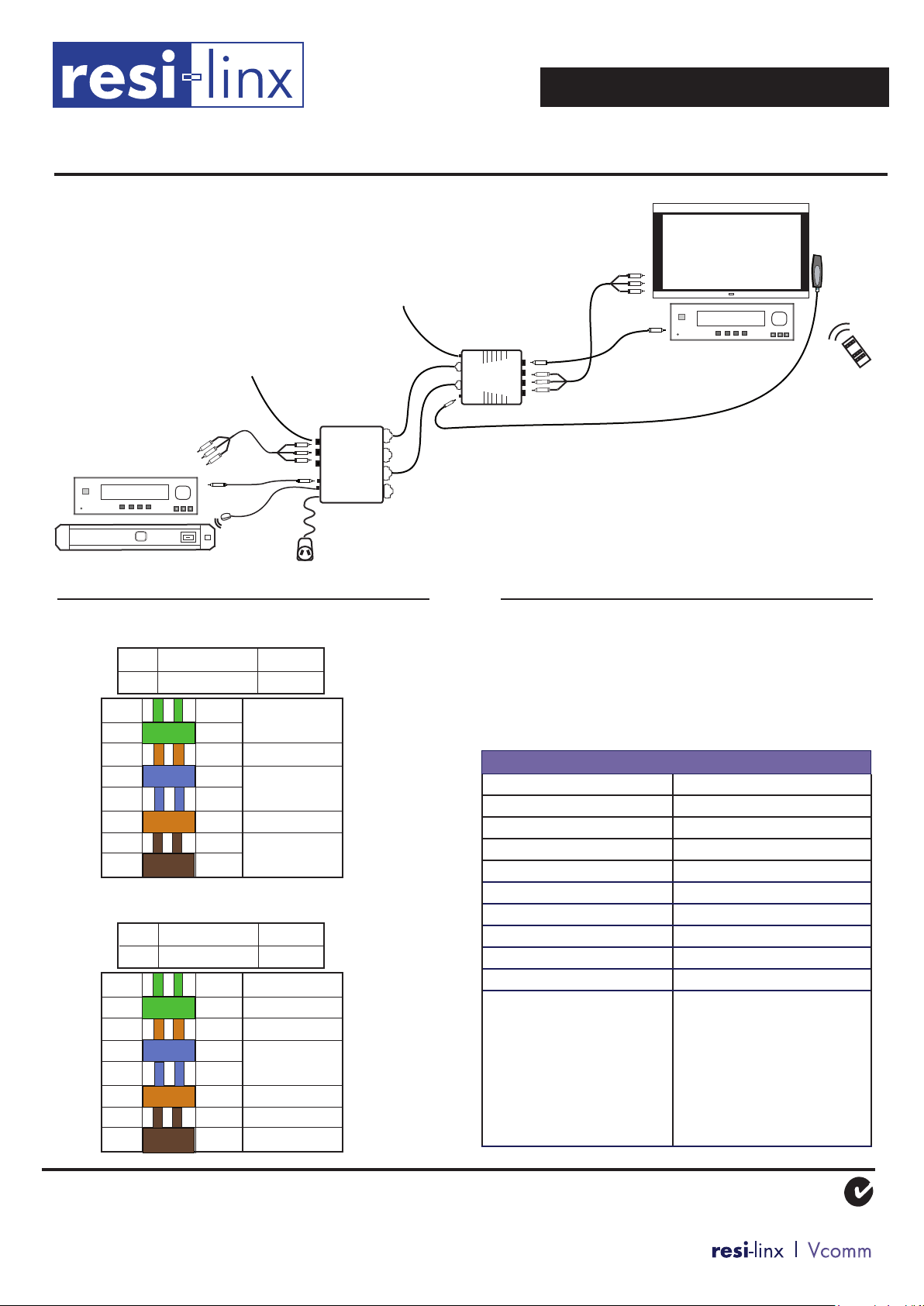
Hardware Connection
1. Ensure all power to equipment is switched off prior to
installation.
RL-BV240A
2. Connect RCA cables from Component source to terminals
A of Transmitter.
3. Connect RCA cable from Digital Audio ouput on
Component source to Digital Audio input C of transmitter
4. Connect audio cable from Analogue Audio output on
Component source to Analogue Audio input G on
transmitter (if required)
5. Connect a second RCA cable from loop through terminals
B of Transmitter to the Component input of the local AV
device (TV, etc).
6. Connect RL-IR700/800* IR emitter to output D of
Transmitter. Place the other end within 25cm of the
IR receiver on the Component source (depending on
environmental conditions).
A RCA Component Video inputs
K
B Loop Through RCA Comp. Video outputs
C RCA Digital Audio input
and Loop Through output
D IR Emitter output
E IR / Power LED’s
F 12V DC Power input
G Analogue Audio input
H RCA Component Video output
I RCA Digital Audio output
J IR Target input
K Analogue Audio output
RL-BV250B
8. Connect Component Video RCA lead (red, green,
blue) from RCA Video output H of Receiver to the
corresponding input on the component device (TV, etc).
9. Connect Digital Audio RCA lead (orange) from RCA
Digital Audio output I of Receiver to the corresponding
input on the component device (TV, etc).
10. Connect Analogue Audio lead (green) from Analogue
Audio output K of Receiver to corresponding input of
the component device (TV, etc).
11. Connect RL-BV500* IR target to input J of Receiver.
Flat target can be easily mounted (either directly using
adhesive backing, or by using RL-ACC150* Target
Mount) to the desired location, anywhere within the line
of sight of remote controls.
7. Connect 2 x RJ45 sockets of Transmitter (OUTPUT IA
and OUTPUT IIA) to corresponding INPUT I and INPUT
II Receiver in zone A via 4 pair twisted cable. Repeat for
zones B, C and D. (eg. OUTPUT IB and II B to zone B
INPUT I and II)
WARRANTY
Vcomm Pty Ltd states that the warrant that the customer can rely on is that
provided by the manufacturer. In the event of any warranty claim please
contact us and we will forward it to the manufacturer. The manufacturer will
then determine the extent of their liability. This expressly negates, to the
extent possible by Australian law, any warranty reliance on Vcomm Pty Ltd.
12. Repeat steps 8 - 11 for connection of zones B, C and D.
13. Connect supplied 12V DC switch mode power pack to
power input F on Transmitter.
14. Once installation is complete, switch on power to
all equipment. Check green PWR LE
Transmitter is illuminated.
D E on
* Sold separately
Vcomm Pty Ltd
ABN: 99 091 281 524
‘linx-AV’ Quad IR Component Video/Audio Balun Transmitter (1:4)
www.resi-linx.com
INSTALLATION MANUAL
®
AV Distribution Range
RL-BV240A / RL-BV250B
IR Component Video/Audio Balun Receiver
Loop Through terminals to
be connected to to local
AV device if required
Pin Conguration
RL-BV240A/250B input 1
+ SOLID POWER
- STRIPED POWER
1 GR/W
2 GR
3 OR/W
4 BL
5 BL/W
6 OR
7 BR/W
8 BR
RL-BV240/250 input 2
+ SOLID POWER
- STRIPED POWER
1 GR/W IR / EARTH
2 GR IR / +12V
3 OR/W
4 BL
5 BL/W
6 OR
7 BR/W
8 BR IR / OP
RL-BV240A
VIDEO
Y
VIDEO Pb / Cb
VIDEO
Pr / Cr
VIDEO Pb / Cb
DIGITAL
AUDIO
AUDIO R
AUDIO
L
AUDIO R
Analogue Audio
if required
Output IIA
Output IA
Zone A
RL-BV250B
Connection to zones B, C and D
as above
Troubleshooting
IR LED indicator on RL-BV240A Transmitter illuminates
briey upon receipt of IR commands.
NOTE: Some brands of TV/Monitors can reduce the
range of the IR Receiver head, which is outside the
scope of the warranty.
RL-BV240A/250B
Power - BV240A
Maximum video input - BV240A
Return loss
Common mode rejection
Maximum distance cable Up to 100m
Video Signal Component
Audio Signal Digital / Analogue
Conguration 1:4
IR capability Yes
Loop Through capability Yes
Connections In/Out - BV240A
- BV250B
12V DC 500mA Switch Mode
>15dB to 1,000 MHz
>40dB @ 1,000 MHz
2 sets - 3 x RCA
1 x IR Emitter
1 x Analogue Audio
3 x RCA Video
1 x RCA Audio
1 x IR Target
1 x Analogue Audio
RL-BV500
Remote
Control
1.2V P-P
8 x RJ45
2 x RJ45
WARRANTY
Vcomm Pty Ltd states that the warrant that the customer can rely on is that
provided by the manufacturer. In the event of any warranty claim please
contact us and we will forward it to the manufacturer. The manufacturer will
then determine the extent of their liability. This expressly negates, to the
extent possible by Australian law, any warranty reliance on Vcomm Pty Ltd.
Vcomm Pty Ltd
ABN: 99 091 281 524
 Loading...