


1
User’s Manual
for
FlexiLogics
TM

2
COPYRIGHT NOTICE
This manual is a publication of Renu Electronics Pvt. Ltd. and is provided for use by its customers only.
The contents of the manual are copyrighted by Renu Electronics; reproduction in whole or in part, for use other than in
support of Renu Electronics equipment, is prohibited without the specific written permission of Renu Electronics.
SERVICE
If service is required then pack the unit in its original packaging container or, if unavailable, any suitable rigid container.
If a substitute container is used, surround the unit with shock absorbing material; damage in shipment is not covered
by the warranty. Include a letter with the unit describing the dif ficulty and Hardware Revision and Software Version.
Send to the following address:
Renu Electronics Pvt. Ltd.
Survey No. 2/6,
Baner Road,
Pune-411045
All returns will be tested to verify customer claims of noncompliance with the product warranty. Improper return
packaging, which makes verification impossible, will void the warranty . If noncompliance is verified and is not due to
customer abuse or the other exceptions described with product warranty , Renu Electronics will, at its option, rep air or
replace the Product returned to it, freight prepaid, which fail to comply with the foregoing warranty , provided REPL is
notified of such noncompliance within the one-year warranty period.
ASSISTANCE
This manual is designed to provide the necessary information for trouble-free installation and operation of your new
FlexiLogics Series. However, if you need assistance, please call Renu Electronics Pvt. Lt d. at 91-20-27292840 or
visit our web site at www.renuelectronics.com
MANUAL REVISION
If you contact us in reference to this manual, please include the following document number
Name : User Manual For FlexiLogics
Part Number : URML104
Document : UMAN\FL\0110
Revision : 1.02B

3
Revision Number Document Number Date Description
Rev 1.00 UMAN\FL\01 10 21-01-2010 First Release
Rev 1.01 UMAN\FL\01 10 10-09-2010 FlexiLogics features revised
Rev 1.02 UMAN\FL\01 10 10-09-2010 FlexiLogics manual revised for images &
other corrections
Rev 1.02A UMAN\FL\01 10 12-01- 201 1 Timings of ON/OFF pulse width is corrected on Pg. 85,
86, 88 & 90.
Rev 1.02B UMAN\FL\01 10 27-08- 201 1 Battery life specifications are corrected and
addition of communication baud rates.
Product configuration GUI changed.
Weights for FL series models are updated.
Revision History:

4
Warranty Certificate
For New product: This product is warranted against defects in materials and workmanship for a period of 12 months
from the date of shipment to Buyer.
For Rectified Products: Any product that will be replaced will have W arranty for 6 months or upto Original Product
Warranty period whichever is greater .
The warranty is limited to repair or replacement of the defective unit at the option of the manufacturer . This warranty is
void if the product has been altered, misused, dismantled, or otherwise abused.
ALL OTHER WARRANTIES, EXPRESSED OR IMPLIED, ARE EXCLUDED, INCLUDING BUT NOT LIMITED TO THE
IMPLIED WARRANTIES OF MERCHANTABILITY AND FITNESS FOR A PA R TICULAR PURPOSE.
MAINTENANCE & SERVICE : There are no parts that can be serviced by the user. Service should be performed on a
unit substitution basis only . Do not attempt to remove, replace or service any printed circuit board, components or any
hardware/software related with display product. If problem within the display product occurs, contact the factory for
service information or repair .
NOTE : Renu Electronics Pvt. Ltd. is dedicated to providing complete customer service and customer satisfaction. If you
have any comments or criticisms about how to improve the product features/reliability, please make a note of the
problem/improvement and notify us. We are always open to new ideas and improvements. So please let us know your
ideas and comments.
IMPORTANT
FlexiLogics Series Products are Programmable Logic Controller modules which
actually take control actions. It is assumed that the user is well acquainted with the PLC
system being used and Windows based software usage, in general.
Never use
FlexiLogics units to perform emergency STOP applications. It is advised that separate
switches be used outside the PLC for ANY emergency Stops.
Any Mechanical or Electrical Modification to this Unit will
void all Warranties.

Table of Content
5
Doc No: UMAN/FL/01 10
Rev No.: 1.00
Table of Contents
INTRODUCTION 7
1.1 Purpose of this manual 8
1.1.1 FlexiLogics Basics 8
1.1.2 Hardware Requirements 9
1.2 Features 10
1.3 FlexiLogics Overview 11
1.3.1 What is a FlexiLogics series unit? 11
1.3.2 How FlexiLogics Works? 13
1.4 Specifications of FlexiLogics Series 21
1.4.1 Comparison between basic models (FL010 & FL011) 22
1.4.2 Comparison between basic models (FL050 & FL051) 23
1.4.3 Specification for Basic Models 24
FL010 24
FL01 1 27
FL050 28
FL051 29
1.4.4 Specification for Expansion Models 30
FLD1600 30
FLD0016P (PNP Type transistor output) 31
FLD0016N (NPN T ype transistor output) 32
FLD0016R (Relay T ype output) 33
FLD0808R (Relay T ype transistor output) 34
FLD0808P (PNP Type transistor output) 34
FLD0808N (NPN T ype transistor output) 34
FLA0800L 38
FLA0800R 40
FLA0004 42
FLA0402U 44
HARDWARE 48
2.1 Unpacking The Unit 49
2.2 Managing Electrostatic Discharge 49
2.3 CE Compliance 49
2.4 Environmental Consideration 49
2.5 Safety Precaution 50
2.6 Installation Instruction 5 0
2.7 Installation Instructions 52
2.7.1 Panel Mounting 52
2.8 Wiring Diagram 56
2.9 Communication Ports 56
2.10 Communication Cables 58
BEFORE YOU BEGIN 63
3.1 Installing FlexiSoft configuration software: 64
3.2 Step s for starting FlexiSoft Software 67
3.3 Uninstalling FlexiSoft Software 67
3.4 Procedure to launch ladder in FlexiSoft 68
3.5 Creating sample ladder 70
CONFIGURATION 73
4.1 Configuring unit using FlexiSoft 74
4.2 Tag Database 77

Table of Content
6
Doc No: UMAN/FL/01 10
Rev No.: 1.00
4.3 Input (XW), Output (YW) and configuration (MW) Register allocation 81
SPECIAL INPUT AND OUTPUT 84
5.1 Special I/O Function overview 85
5.2 High Speed Counter Design 86
5.2.1 Single Phase Counter 89
5.2.2 Single Phase speed - counter 90
5.2.3 Quadrature bi-pulse counter 91
5.2.4 Interrupt Input Function 93
5.2.5 Pulse Output Function 93
5.2.6 PWM Output Function 94
OPERATING SYSTEMS OVERVIEW 95
6.1 Operating System Overview 96
PROGRAMMING INFORMA TION 97
7.1 Devices Registers 98
7.2 Memory Allocation of XW, YW and MW 105
7.3 Index Modification 107
7.4 Real-time clock / calendar 109
7.5 User program 110
7.5.1 Main Program 1 10
7.5.2 Sub-program # 1 111
7.5.3 Timer interrupt program 111
7.5.4 I/O interrupt program 1 11
7.5.5 Subroutines 112
7.6 Programming Language 113
7.7 Program execution sequence 114
TROUBLESHOOTING 115
8.1 Troubleshooting Procedure 1 16
8.1.1 Power Supply Check 117
8.1.2 CPU Check 117
8.1.3 Program Check 117
8.1.4 Input Check 118
8.1.5 Output Check 119
8.1.6 Environmental Problem 120
8.2 Self Diagnosis 121
MAINTENANCE AND CHECKS 126
9.1 Precautions during operation 127
9.2 Daily Checks 128
9.3 Periodic Checks 129
9.4 Spare Parts 130

Introduction
7
Doc No: UMAN\FL\01 10
Rev . No.: 1.02B
INTRODUCTION
In this chapter. . . .
♦ Purpose of this manual
FlexiLogics Basics
Hardware Configuration
♦ FlexiLogics Features
♦ FlexiLogics Overview
What is FlexiLogics series unit?
How FlexiLogics works?
FlexiLogics Specifications

Introduction
8
Doc No: UMAN\FL\01 10
Rev . No.: 1.02B
1.1 Purpose of this manual
Thank you for purchasing FlexiLogics Series Products from Renu Electronics. FlexiLogics Series Products are
versatile high-performance programmable controllers with Microsoft® Windows based configuration Software.
This Manual explains the operation of the FlexiLogics Series and how to implement available features using the
FlexiSoft Software. This manual will help you to install, configure and operate your FlexiLogics product.
1.1.1 FlexiLogics Basics
FlexiLogics provide much more versatility than traditional programmable controllers. FlexiLogics unit supports basic
relay ladder functions. In addition to this it provides functions such as data operations, arithmatic operations, various
functions etc. Furthermore, its high speed counter functions, pulse output functions, and data communication
functions allow its application to a wide scope of control systems.
What is a Project?
A project is an user created application in FlexiSof t Software. A project cont ains information such as FlexiLogics
model, Network Configuration, ladder information, etc.
What is a Ladder?
Y ou use Ladder Logic to write your project application. Ladder is based on Boolean principals. Ladder Diagrams are
composed of different types of contact, coil and function block elements. These elements are placed in nets.
In any Ladder Diagram, the contacts represent input conditions. They lead power from the left rail to the right
rail. Coils represent output instructions. In order for output coils to be activated, the logical state of the contacts
must allow the power to flow through the net to the coil.

Introduction
9
Doc No: UMAN\FL\01 10
Rev . No.: 1.02B
1.1.2 Hardware Requirements
The following basic PC hardware configuration is needed to configure and operate your FlexiSoft Configuration Software.
Minimal PC configuration for Windows2000 / XP:
DEVICE RECOMMENDED
Processor 800MHz Pentium processor OR euivalent processor
Operating System Microsoft Windows 2000 with SP4
Microsoft Windows XP Professional / Home Edition with SP2
RAM 256MB
Hard Disk Sp ace 800MB (including 200MB for the .NET Framework Redistributable)
Display 1024 x 768 High Color 16-bit
Mouse/Keyboard Required
Minimal PC configuration for Vista:
DEVICE RECOMMENDED
Processor 1GHz Pentium processor or equivalent processor
Operating System Microsoft Windows Vista Home and Vista Business edition
RAM 1GB
Hard Disk Sp ace 800MB (including 200MB for the .NET Framework Redistributable)
Display 1024 x 768 High Color 16-bit
Mouse/Keyboard Required
These are the minimum system requirements for a computer running the FlexiSoft Configuration software.

Introduction
10
Doc No: UMAN\FL\01 10
Rev . No.: 1.02B
1.2 Features
Expansion Models:
The following are the digital expansion models:
-> 16 points DC input
-> 16 points DC output (NPN T ype)
-> 16 points DC output (PNP T ype)
-> 16 points DC output (Relay T ype)
-> 8 DC inputs + 8 DC outputs (NPN type)
-> 8 DC inputs + 8 DC outputs (PNP type)
-> 8 DC inputs + 8 DC outputs (Relay type)
The following are the analog expansion models:
-> 4 Universal Analog input s & 2 analog outputs (V-I Type)
-> 8 Analog input s (Linear Type)
-> 8 Analog input s (RTD T ype)
-> 4 Analog outputs (V -I T ype)
Built-in high speed counter:
Two single-phase or one quadrature (2-phase) pulses can be counted. In single phase mode, up to 50KHz
and in quadrature mode, up to 5KHz frequency can be counted.
High speed processing:
Sophisticated machine control applications require high speed data manipulations. The FL is designed to
meet these requirements.
· 1.4 ms per contact · 2.3 ms per coil
· 4.2 ms per 16-bit transfer · 6.5 ms per 16-bit addition
The FlexiLogics also supports interrupt input function (DC input type only). This allows immediate operation
independent of program scan.
High performance software:
The FlexiLogics offer various basic ladder instructions and other functional instructions. Subroutines,
Interrupt functions, Indirect addressing, For/Next loops, Pre-derivative real PID, etc. are standard on the
FlexiLogics unit. These functions allow the unit to be applied to the most demanding control applications.
Pulse output / PWM output:
One point of variable frequency pulses (max. 5 kHz) or variable duty pulses can be output. These functions
can be used to drive a stepping motor or to simulate an analog output. (DC input type only)
Removable terminal blocks:
The FlexiLogics are equipped with removable terminal blocks. This supports the easy maintenance work.
Real-time clock/calendar function:
The FlexiLogics has the real-time-clock/calendar function (year, month, day, day of the week, hours,
minutes, seconds) that can be used for performing scheduled operations, data gathering with time stamps,
etc. The real-time-clock/calendar data is backed up by a removable and replacable battery .
RS-485 multi-purpose communication port:
The FlexiLogics unit has an RS-485 multi-purpose communication port. Using this port, one of the following
communication modes can be selected.
Computer link mode: T-series computer link protocol can be used in this mode. Up to 32 FlexiLogics can
be connected to a master computer. By using this mode, MMI/SCADA system can be easily configured.
Data link mode: T wo PLCs can be directly linked together . This direct link is inexpensive, easily configured and requires no special programming.
Free ASCII mode: User defined ASCII messages can be transmitted and received through this port. A
terminal, printer, bar-code reader , or other serial ASCII device can be directly connected.
Introduction
11
Doc No: UMAN\FL\01 10
Rev . No.: 1.02B
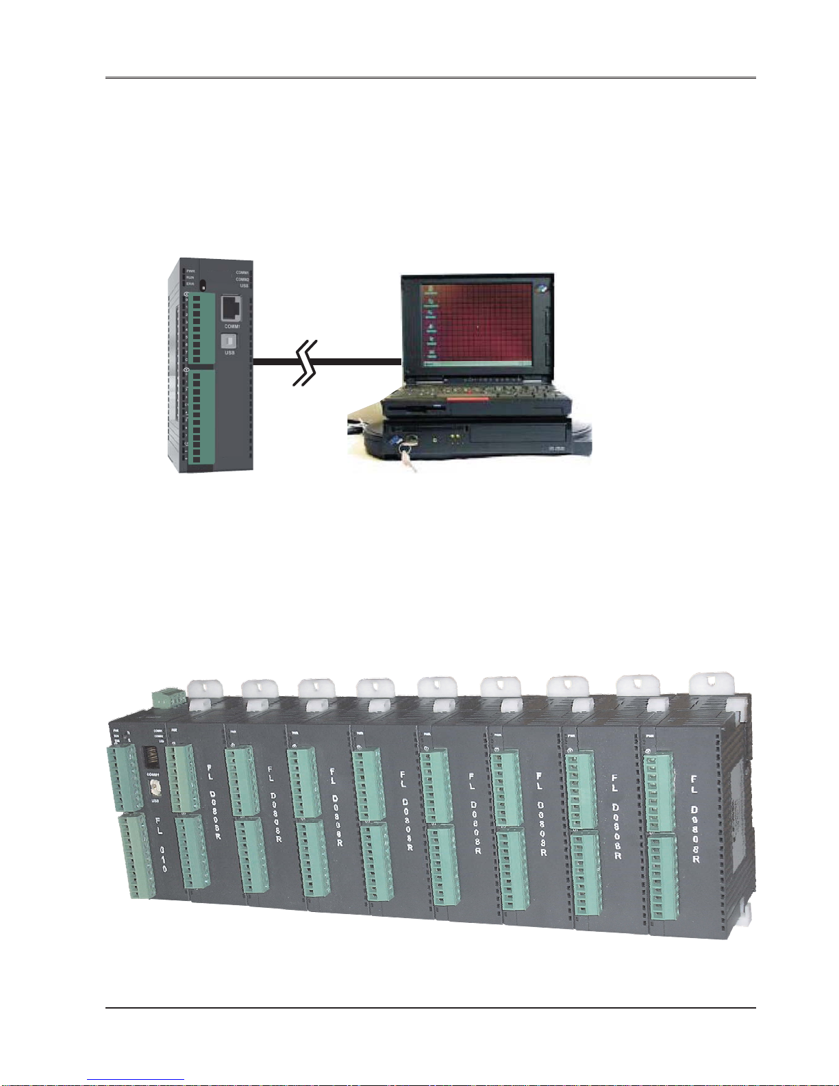
1.3 FlexiLogics Overview
1.3.1 What is a FlexiLogics series unit?
FlexiLogics Series units are compact, easy-handling block style programmable controller . It also has modular
expandability.
Configuration of FlexiLogics unit:
Each FlexiLogics base unit has to be configured using the FlexiSoft Software before connecting it to the system.
Normal Operation:
The FlexiLogics family is designed to offer practical PLC features in a compact and expandable design, and at the
same time offer a simple-to-use philosophy . An external powered FlexiLogics series base models by itself can be
used as a complete PLC system with optional built-in I/O points, or the system can be expanded with the addition of
up to eight I/O modules.
The FlexiLogics can be mounted in DIN rail plate. The base CPU and I/O modules are connected together via an
expansion port on the sides of the modules. A variety of I/O modules are available for flexible and optimal system
configuration.
R
H
F
L
0
1
0
FIG-1: FlexiLogics Base with eight expansions

Introduction
12
Doc No: UMAN\FL\01 10
Rev . No.: 1.02B
Application Examples1:
HMI FlexiLogics PLC base unit PLC
As shown above, FlexiLogics base unit can be connected to another PLC as well as to HMI. Thus can be worked
with two different protocols at a time.
Application Examples2:
SCADA FlexiLogics PLC base unit HMI
As shown above, FlexiLogics base unit can be connected to SCADA as well as HMI.

Introduction
13
Doc No: UMAN\FL\01 10
Rev . No.: 1.02B
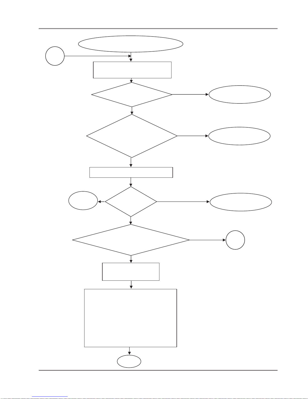
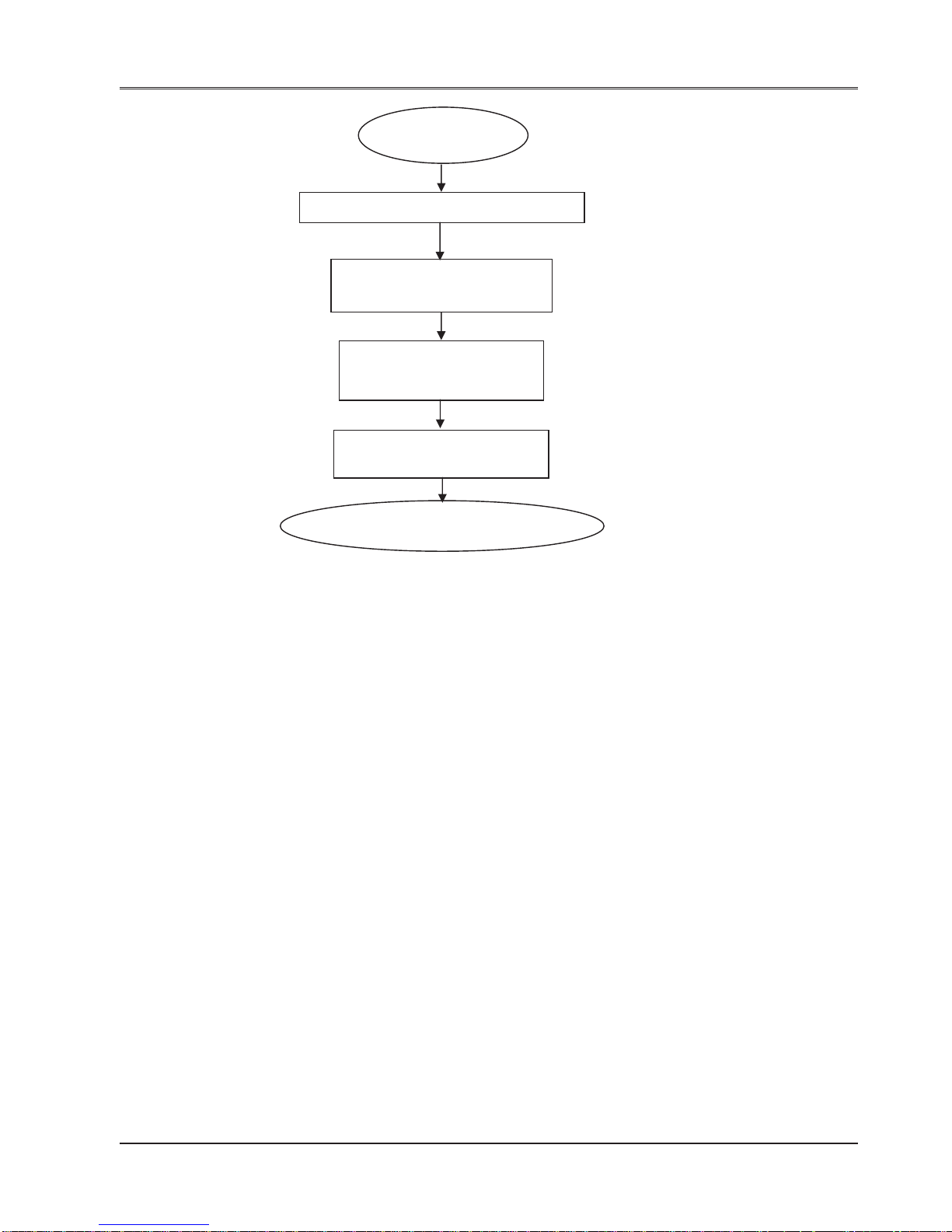
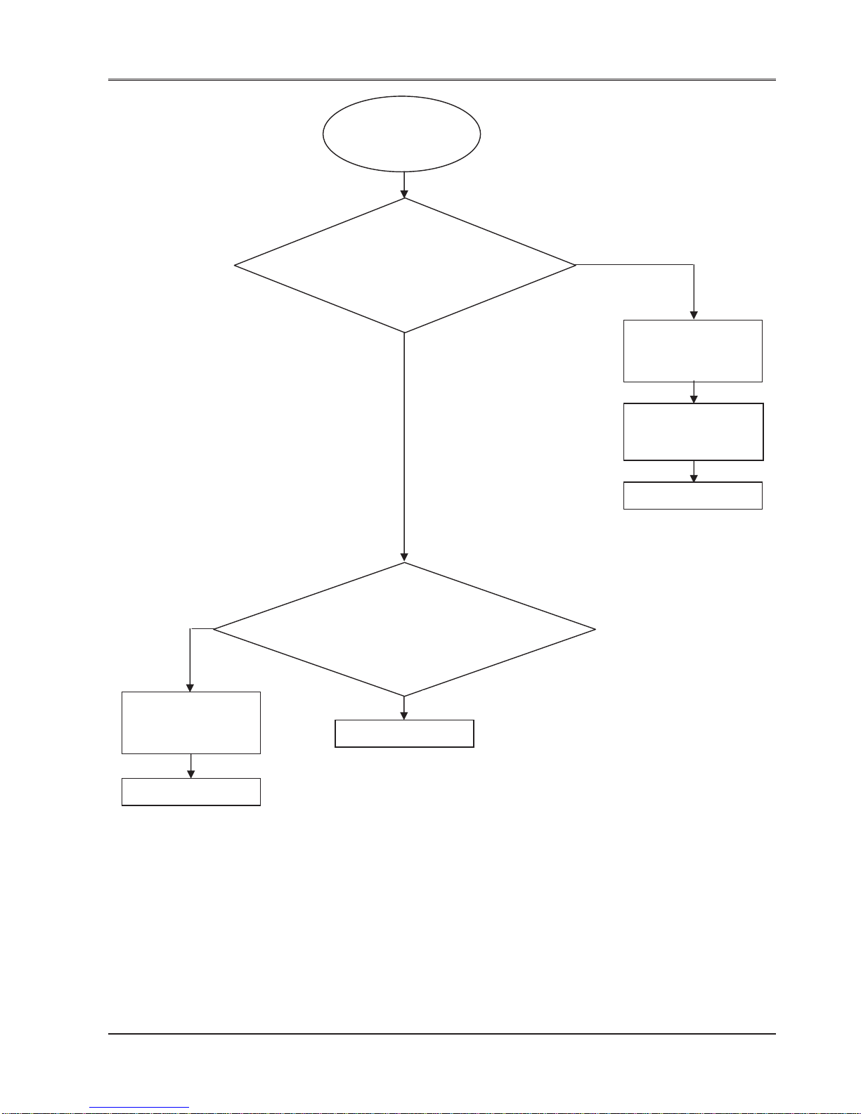
1.3.2 How FlexiLogics Works?
The FlexiLogics follows a specific sequence and the sequence is as shown below:
No
Yes
Initialize
Watchdog
Check for
valid
Ladder
Check for
Valid
Firmware
Initialize serial and
USB ports
Wait till Firmware
Download. Flash
Error and RUN led
at 1 sec interval
Soft restart
Initialize serial and
USB ports
Wait till Ladder
Download.
Flash Error led at 1
sec interval.
Soft restart
Ye s
Check for
valid
Application
Initialize serial and
USB ports
Wait till Application
Download.
Flash Error led at 1
sec interval.
Soft restart
No
No
A
START
Ye s

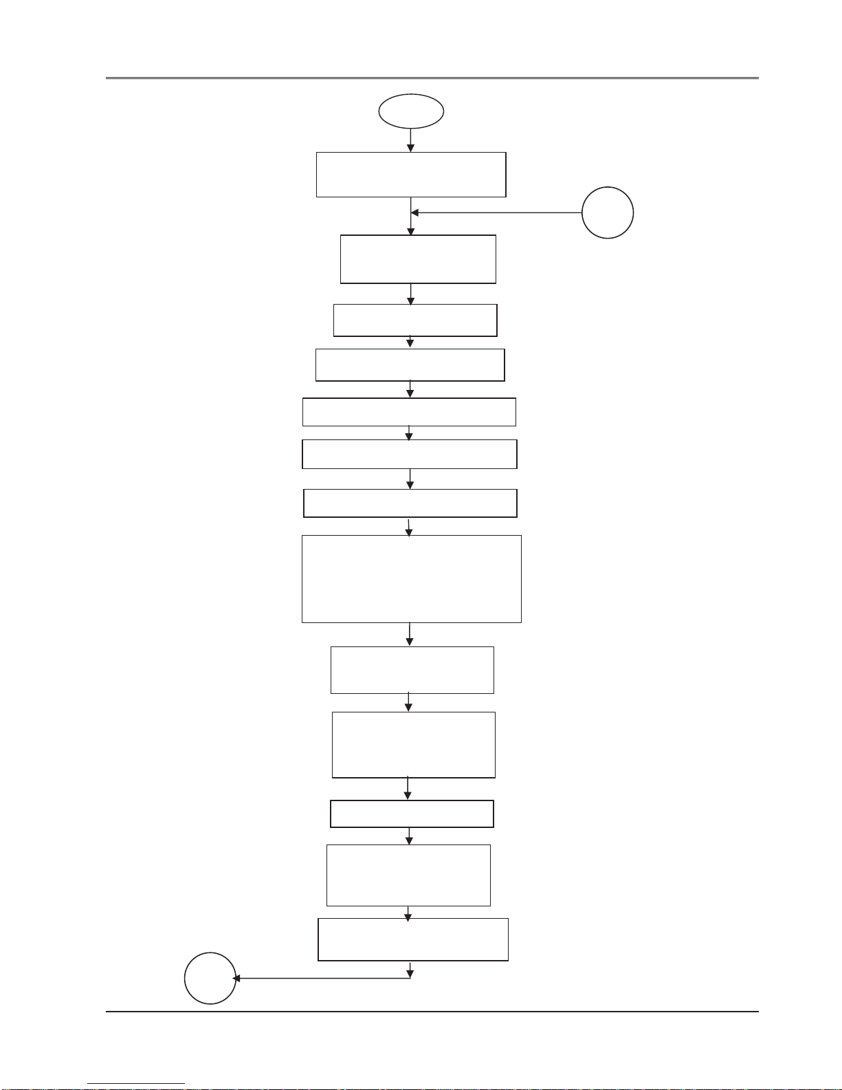
Introduction
14
Doc No: UMAN\FL\01 10
Rev . No.: 1.02B
Set internal configuration according
to application. ( Base Timer,
(100uSec) Timer 1, IO configuration
and other system parameter read )
Initialize USB
Restore Keep memory data,
Event History
A
Detect the expansion modules and
update Expansion module information
( Only at Power on)
Read the ladder address information.
Main Loop Start
Clear All PLC registers
expansion module
information and event history
Configure communication channel and
detect slave serial devices.( if master )
Check for
type of
restart
Power On Reset
Soft restart
Clear All PLC registers
except keep memory,
CPU Watchdog reset
Power Up Self Diagnosis
Set Power On system bit to ‘1’
Introduction
15
Doc No: UMAN\FL\01 10
Rev . No.: 1.02B
RUN Position
Read
RUN/STOP
Switch
Turn On RUN Led
Clear non retentive PLC registers.
Execute Power-On Tasks.
Execute Power-Up ladder.
Enable User Timer Interrupt.
Initialize digital filter constant to
default 10 mSec.
Reset Power On system bit to ‘0’
HALT MODE
STOP Position
Self Diagnosis
ERROR MODE
Error Down
OK
Mode
check
RUN Mode or Switch position
change from Stop to RUN
Halt Mode
HALT MODE
Start counting Main Loop
Scan Time
Update PLC mode from software
Main Loop Start
HOLD
If power On System
bit is ‘1’
Hold Mode
Ye s
No
B
Scan Local and
expansion inputs
C
D
Introduction
16
Doc No: UMAN\FL\01 10
Rev . No.: 1.02B
Scan Local and
expansion inputs
Execute Global Tasks
B
Feed the CPU watch-dog
Execute main Ladder
Execute First Scan operations
(1. Initialize special inputs and
outputs. 2. Load Digital filter
constant.)
Update High speed
counter registers
Update local,
expansion and PWM
outputs
Feed watch-dog
Respond to the
monitor query (if any)
on USB.
Start counting ladder scan time
Stopcountingladderscantime
Stop counting main loop
scan time
Update local, expansion.
C
D
Introduction
17
Doc No: UMAN\FL\01 10
Rev . No.: 1.02B
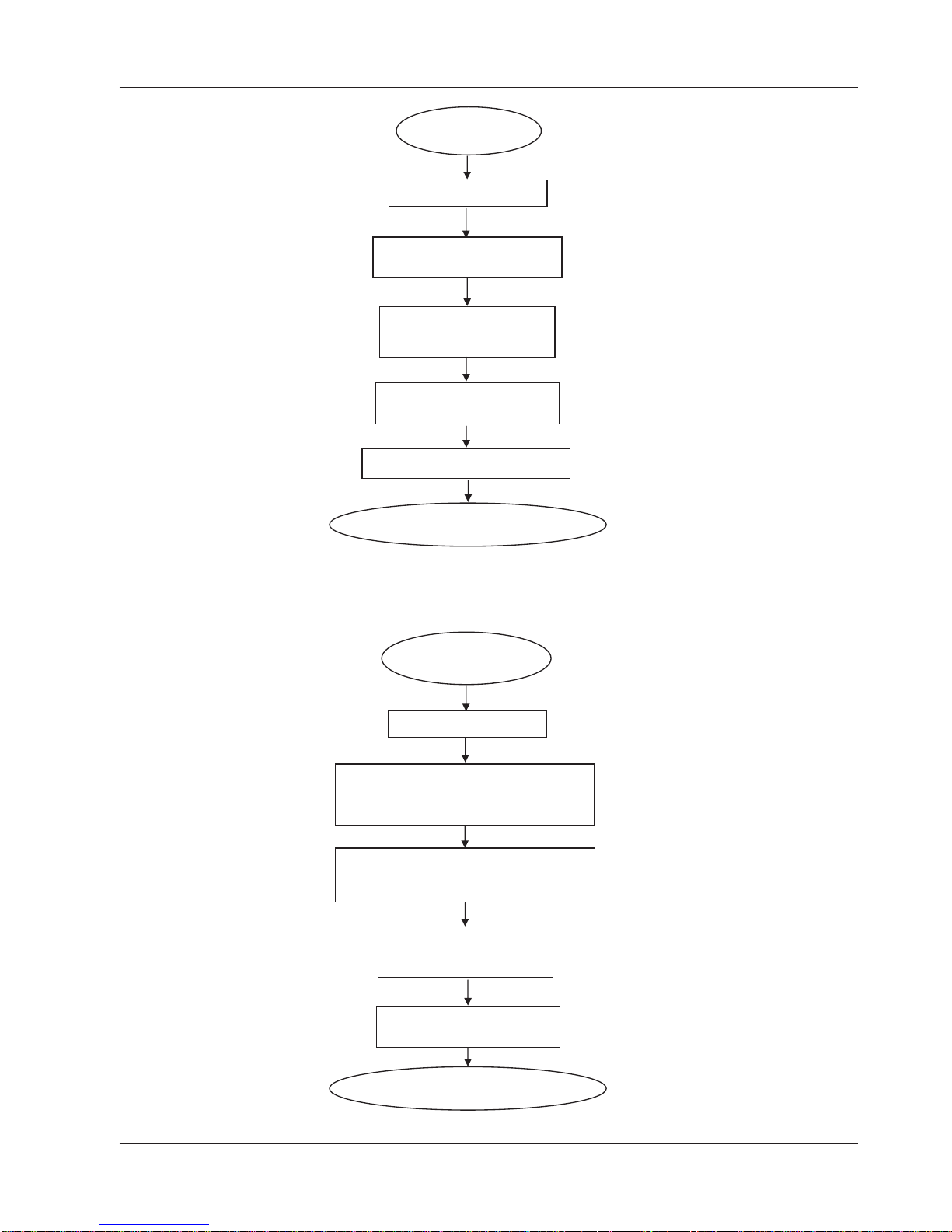
HALT MODE
Feed Watch-dog
Turn OFF all Outputs and
RUN Led
Respond to the monitor
query (if any) on USB.
Stop counting main loop
scan time
Main Loop Start
Set Power On system bit to ‘1’
Feed Watch-dog
Turn ON ERROR Led.
Turn OFF RUN Led.
ERROR MODE
Set the state of output as per ‘ERROR
STATE OUTPUT CONDITION’
(Local, expansion and PWM)
Respond to the monitor
query (if any) on USB.
Stop counting main loop
scan time
Main Loop Start
Introduction
18
Doc No: UMAN\FL\01 10
Rev . No.: 1.02B
HOLD MODE
Read Local and Expansion Inputs
Update Local, Expansion
and PWM outputs
Respond to the monitor
query (if any) on USB.
Stop counting main loop
scan time
Main Loop Start

Introduction
19
Doc No: UMAN\FL\01 10
Rev . No.: 1.02B
Power-Up Self
Diagnosis
if
1. IO Mismatch
2. CPU Watchdog reset
Log event in
Event History
Set Error down
mode flag
Return
if
1. RTC error
2. Retentive data loss
Return
No
Ye s
Log event in
Event History
Return
Ye s
No
Introduction
20
Doc No: UMAN\FL\01 10
Rev . No.: 1.02B
Self Diagnosis
if
1. IO BCC error
Log event in
Event History
Set Error down
mode flag
Return
if
1. User watchdog error
2. Scan time over error
Return
No
Ye s
Log event in
Event History
Return
Ye s
No

Introduction
21
Doc No: UMAN\FL\01 10
Rev . No.: 1.02B
1.4 Specifications of FlexiLogics Series
The FlexiLogics series models possess powerful programmable logic features. User can implement logic, specific to
application using standard Ladder programming.
FlexiLogics models need +24VDC power from an external supply.
Models included in the FlexiLogics Series are as follows:
Basic Models:
FL010 PLC Base model with 8 digital I/Ps and 8 Digital O/Ps
FL01 1 PLC card with 16 digital I/Ps and 16 Digital O/Ps
FL0 50 PLC Base model with ethernet
FL0 5 1 PLC card with ethernet and 16 digital I/Ps and 16 Digital O/Ps
Expansion models:
FLD1600 16 Input Digital Module
FLD0016P 16 PNP type transistor output digital module
FLD0016N 16 NPN type transistor output digital module
FLD0016R 16 Relay type output digital module
FLD0808P 8 Digital input, 8 PNP type transistor output digital module
FLD0808N 8 Digital input, 8 NPN type transistor output digital module
FLD0808R 8 Digital input, 8 Relay type output digital module
FLA0800L 0-10 VDC or 4-20 mA (16 Bit), 8 channels input.
FLA0800R RTD PT100 (16 Bit), 8 channels input.
FLA0004 4 channel 0-10 VDC or 4-20 mA (16 Bit) Output.
FLA0402U 4 channel Universal Analog Inputs ( RTD PT100, TC, 4-20 mA, 0-20mA, 0-
50mV , 0 - 100mV, 0-10VDC), 16 Bit
2 channel 0-10 VDC or 4-20 mA (16 Bit) Output

Introduction
22
Doc No: UMAN\FL\01 10
Rev . No.: 1.02B
1.4.1 Comparison between basic models (FL010 & FL011)
Functional Specific. FL0 10 FL01 1
Case FlexiLogics Case Open PCB with DIN rail Mounting
Ladder Program 8K Steps 8K Steps
Memeory
Expansion I/O capacity Maximum 8 expansion None
modules
Expansion Bus SPI (1MHz) SPI (1MHz)
Local I/Os 16 ( 8 IN / 8 OUT). 32 ( 16 IN / 16 OUT )
Processing time 1 uSec. for NO/NC 1 uSec. for NO/NC
Input registers 400 Words Max. 400 Words Max.
Output registers 400 Words Max. 400 Words Max.
Data registers 4096 words 4096 words
Retentive registers 1400 words (EEPROM) 1400 words (EEPROM)
System registers 256 words 256 words
Configuration Register 1600 words Max. 1600 words Max.
Timer Registers 256 words 256 words
Counter Registers 256 words 256 words
Timer Devices 256 points 256 points
Counter Devices 256 points 256 points
HS Counter 2 HS counter inputs, single 2 HS counter inputs, single
phase. (50KHz). 32 bit. phase. (50KHz). 32 bit.
System Coil 100 points 100 points
Communication ports 2 COM ports. 2 COM ports.
COM1: RS232 and RS485. COM1: RS232.
COM2: 2-wire RS-485 COM2: 2-wire RS-485
One USB port for programming. One USB port for programming.
Ethernet - -
Power Supply Spec.:
Supply Volt age 24VDC, +/-15% 24VDC, +/-15%
Maximum Input current 150mA at 24VDC 150mA at 24VDC (Without expansion)
(Without expansion)
Inrush Current 8A at 24VDC (Without 8A at 24VDC (Without expansion)
expansion)
Dielectric Strength 1500 VDC, 1 minute 1500 VDC, 1 minute
(PS and internal circuit)
Insulation Resistance Minimum 5M ohm Minimum 5M ohm
(PS and internal circuit)

Introduction
23
Doc No: UMAN\FL\01 10
Rev . No.: 1.02B
1.4.2 Comparison between basic models (FL050 & FL051)
Functional Specific. FL0 50 FL0 51
Case FlexiLogics Case Open PCB with DIN rail Mounting
Ladder Program 8K Steps 8K Steps
Memeory
Expansion I/O capacity Maximum 8 expansion None
modules
Expansion Bus SPI (1MHz) SPI (1MHz)
Local I/Os - 32 ( 16 IN / 16 OUT )
Processing time 1 uSec. for NO/NC 1 uSec. for NO/NC
Input registers 400 Words Max. 400 Words Max.
Output registers 400 Words Max. 400 Words Max.
Data registers 4096 words 4096 words
Retentive registers 1400 words (EEPROM) 1400 words (EEPROM)
System registers 256 words 256 words
Configuration Register 1600 words Max. 1600 words Max.
Timer Registers 256 words 256 words
Counter Registers 256 words 256 words
Timer Devices 256 points 256 points
Counter Devices 256 points 256 points
HS Counter - 2 HS counter inputs, single
phase. (100KHz). 32 bit.
System Coil 100 points 100 points
Communication ports 2 COM ports. 2 COM ports.
COM1: RS232 and RS485. COM1: RS232.
COM2: 2-wire RS-485 COM2: 2-wire RS-485
One USB port One USB port
Ethernet 10/100 Mbps ethernet port 10/100 Mbps ethernet port
Power Supply Spec.:
Supply Volt age 24VDC, +/-15% 24VDC, +/-15%
Maximum Input current 330mA at 24VDC 330mA at 24VDC (Without expansion)
(Without expansion)
Inrush Current 8A at 24VDC (Without 8A at 24VDC (Without expansion)
expansion)
Dielectric Strength 1500 VDC, 1 minute 1500 VDC, 1 minute
(PS and internal circuit)
Insulation Resistance Minimum 5M ohm Minimum 5M ohm
(PS and internal circuit)

Introduction
24
Doc No: UMAN\FL\01 10
Rev . No.: 1.02B
1.4.3 Specification for Basic Models
FL010
Power Supply 24VDC, 330mA
Input per channel 24 VDC, 5mA & 20mA (for CH0 & CH1)
Output per channel 230V / 2A or 24VDC / 2A for Relay,
0.5A at 24VDC for transistor
Approvals CE, UL
Memory
Total Program Memory 8K Steps
User Data
Input Registers 400 Words / 6400 pts. (Max.*)
Outout Registers 400 Words / 6400 pts. (Max.*)
Data Registers 4096 words
Retentive Registers 1400 words (EEPROM)
System Registers 256 words
Timer Registers 256 words
Counter Register 256 words
Timer Devices 256 points
System Devices 100 points
Counter Devices 256 points
Configuration Register 1600 Words / 25600 pts. (Max.*)
Communication Ports
2 COM Ports: COM1: RS232 and RS485
COM2: 2-wire RS485
1 USB: For programming
Special Input Function
HS Counter 2HS Counter inputs, single
phase (50 KHZ), 32 Bit
Dual Phase 1X, 2X, 4X (5KHz)
Interrupt Input 2 Points
PWM Output CW / CCW OR PLS / DIR
Connection method Removable terminals
(3.81mm pitch)
General
Operating Temperature 0 to 55 deg.C.
Storage Temperature -20 to 85 deg.C.
Operating Humidity 10% to 90% (Non
condensing)
Vibration Tests Frequency 10Hz to 150hz
Displacement +/- 0.35mm
Crossover frequency 59Hz
Acceleration: 2g
Sweep rate : 1 octave per min
Duration : 20 Sweeps / Axis
app (2Hr 30min) Axis , X,Y, Z
Shock Test 25 g acceleration with 11 ms
3 Shocks each AXIS (a total
of 18 Shocks)
Mechanical Dimension 100mm X 35mm X 70mm
Weight Approx. 180 gm.
IO Specifications:
Expansion IO capacity 8 expansion modules
Expansion Bus SPI (1 MHz)
Local IOs 16 (8 IN / 8 OUT)
Digital Inputs 8 Bidirectional Digital inputs (2 High
Speed inputs of upto 50KHz). 8 points
per common.
Rated Input voltage 24VDC
Rated Input Current Upto 5mA. (20mA for High Speed I/Ps)
Input Impedance 5.4Kohm (1.2Kohm for High Speed
i/ps)
Minimum ON voltage 9.6 VDC
Maximum OFF voltage 3.6 VDC
Turn ON time 10 msec
Turn OFF time 10 msec
Isolation Optically isolated from internal circuit
Digital outputs 6 Relay (Form A) outputs. 3 points per
common. 2 Transistor Output
Output Capacity 2A per o/p for Relay (6A per
common), 0.5 A for transistor
Rated load 230V / 2A, 30VDC / 2A for Relay ,
0.5 A at 24VDC for transistor
Note:
* : Depends upon I/O allocation.
R
H
F
L
0
1
0

Introduction
25
Doc No: UMAN\FL\01 10
Rev . No.: 1.02B
Wiring Diagram for Digital I/Ps and O/Ps of model FL010:
1. Wiring diagram for testing digital inputs:
Note: X0 and X1 are high speed input
Wiring for transistor type outputs:
X0
X1
X2
X3
X4
X5
X6
X7
24VDC
+
-
SW1
SW2
SW3
SW4
SW5
SW6
SW7
SW8
C
Closing Swx will turn on respective inputs
R
H
F
L
0
1
0
LOAD
Internal
Circuit
Y1
-
+
24VDC
LOAD
Internal
Circuit
Y2
-
+
24VDC
Transistor
type O/P
R
H
F
L
0
1
0

Introduction
26
Doc No: UMAN\FL\01 10
Rev . No.: 1.02B
*L1 to L6 are A.C. Load.
R
H
F
L
0
1
0
L2
L3
L1
230 VAC
P
N
L5
L6
L4
230 VAC
P
N
Wiring for output connections:

Introduction
27
Doc No: UMAN\FL\01 10
Rev . No.: 1.02B
FL011
Power Supply 24VDC, 330mA
Input per channel 24 VDC, 5mA & 20mA for High Speed
inputs (CH1 & CH2)
Output per channel 24VDC; 0.5A
Approvals CE, UL
Memory
Total Program Memory 8K Steps
User Data
Input Registers 400 Words / 6400 pts. (Max.*)
Outout Registers 400 Words / 6400 pts. (Max.*)
Data Registers 4096 words
Retentive Registers 1400 words (EEPROM)
System Registers 256 words
Timer Registers 256 words
Counter Register 256 words
Timer Devices 256 points
System Devices 100 points
Counter Devices 256 points
Configuration Register 1600 Words / 25600 pts. (Max.*)
Communication Ports
2 COM Ports: COM1: RS232
COM2: 2-wire RS485
1 USB: For programming
Special Input Function
HS Counter 2HS Counter inputs, single
phase (50 KHZ), 32 Bit
Dual Phase 1X, 2X, 4X (5KHz)
Interrupt Input 2 Points
Connection method FRC T ype
connector
General
Operating Temperature 0 to 55 deg.C.
Storage Temperature -20 to 85 deg.C.
Operating Humidity 10% to 90% (Non
condensing)
Vibration Tests Frequency 10Hz to 150hz
Displacement +/- 0.35mm
Crossover frequency 59Hz
Acceleration: 2g
Sweep rate : 1 octave per min
Duration : 20 Sweeps / Axis
app (2Hr 30min) Axis , X,Y, Z
Shock Test 25 g acceleration with 11 ms
3 Shocks each AXIS (a total
of 18 Shocks)
Mechanical Dimension 155mm X 102mm
Weight 180 gm
IO Specifications:
Expansion IO capacity None
Expansion Bus SPI (1 MHz)
Local IOs 32 (16 IN / 16 OUT)
Digital Inputs 16 Bidirectional Digital inputs (2 High
Speed inputs of upto 50KHz). 16 points
per common.
Rated Input voltage 24VDC
Rated Input Current Upto 5mA. (20mA for High Speed I/Ps)
Input Impedance 5.4Kohm (1.2Kohm for High Speed
i/ps)
Minimum ON voltage 9.6 VDC
Maximum OFF voltage 3.6 VDC
Turn ON time 10 msec
Turn OFF time 10 msec
Isolation Optically isolated from internal circuit
Digital outputs 16 PNP transistor outputs.
Output Capacity 0.5 A for transistor
Rated load 0.5 A at 24VDC for transistor
Note:
* : Depends upon I/O allocation.

Introduction
28
Doc No: UMAN\FL\01 10
Rev . No.: 1.02B
FL050
F
L
0
5
0
Power Supply 24VDC, 150mA
Input per channel NA
Output per channel NA
Standards CE, UL
Memory
Total Program Memory 8K Steps
User Data
Input Registers 400 Words / 6400 pts. (Max.*)
Outout Registers 400 Words / 6400 pts. (Max.*)
Data Registers 4096 words
Retentive Registers 1400 words (EEPROM)
System Registers 256 words
Timer Registers 256 words
Counter Register 256 words
Timer Devices 256 points
System Devices 100 points
Counter Devices 256 points
Configuration Register 1600 Words / 25600 pts. (Max.*)
Communication Ports
2 COM Ports: COM1: RS232/RS485
COM2: 2-wire RS485
1 USB: For programming
1 Ethernet: 10/100 MBBS
For PLC communication and
Configuration
Note:
* : Depends upon I/O allocation.
IO Specifications:
Expansion IO capacity 8 expansion modules
Expansion Bus SPI (1 MHz)
Local I/Os None
General
Mechanical Dimension 100mm X 35mm X 70mm
Weight Approx. 125 gm.

Introduction
29
Doc No: UMAN\FL\01 10
Rev . No.: 1.02B
FL051
Power Supply 24VDC, 150mA
Input per channel 24 VDC, 5mA & 20mA for high speed
inputs (CH1 & CH2)
Output per channel 24VDC; 0.5A
Standards CE, UL
Memory
Total Program Memory 8K Steps
User Data
Input Registers 400 Words / 6400 pts. (Max.*)
Outout Registers 400 Words / 6400 pts. (Max.*)
Data Registers 4096 words
Retentive Registers 1400 words (EEPROM)
System Registers 256 words
Timer Registers 256 words
Counter Register 256 words
Timer Devices 256 points
System Devices 100 points
Counter Devices 256 points
Configuration Register 1600 Words / 25600 pts. (Max.*)
Communication Ports
2 COM Ports: COM1: RS232 and RS485
COM2: 2-wire RS485
1 USB: For programming
1 Ethernet: 10/100 MBBS For PLC communication
and Configuration
IO Specifications:
Expansion IO capacity None
Expansion Bus SPI (1 MHz)
Local IOs 32 (16 IN / 16 OUT)
Digital Inputs 16 Bidirectional Digital inputs (2 High
Speed inputs of upto 50KHz). 16 points
per common.
Rated Input voltage 24VDC
Rated Input Current Upto 5mA. (20mA for High Speed I/Ps)
Input Impedance 5.4Kohm (1.2Kohm for High Speed
i/ps)
Minimum ON voltage 9.6 VDC
Maximum OFF voltage 3.6 VDC
Turn ON time 10 msec
Turn OFF time 10 msec
Isolation Optically isolated from internal circuit
Digital outputs 16 PNP Transistor Output
Output Capacity 0.5 A for transistor
Rated load 0.5 A at 24VDC for transistor
Special Input Function
HS Counter 2HS Counter inputs, single
phase (50 KHZ), 32 Bit
Dual Phase 1X, 2X, 4X (5KHz)
Interrupt Input 2 Points
Connection method FRC T ype
connector
General
Operating Temperature 0 to 55 deg.C.
Storage Temperature -20 to 85 deg.C.
Operating Humidity 10% to 90% (Non
condensing)
Vibration Tests Frequency 10Hz to 150hz
Displacement +/- 0.35mm
Crossover frequency 59Hz
Acceleration: 2g
Sweep rate : 1 octave per min
Duration : 20 Sweeps / Axis
app (2Hr 30min) Axis , X,Y, Z
Shock Test 25 g acceleration with 11 ms
3 Shocks each AXIS (a total
of 18 Shocks)
Mechanical Dimension 155mm X 102mm
Weight Approx. 180 gm
Note:
* : Depends upon I/O allocation.

Introduction
30
Doc No: UMAN\FL\01 10
Rev . No.: 1.02B
1.4.4 Specification for Expansion Models
FLD1600
Wiring Diagram for FLD1600
Digital Inputs 16 Normal Inputs, 8 points per
common. Bidirectional type.
Input per channel 5mA, 24VDC
Output per channel NA
Input Impedance 5.4K ohm
Minimum ON voltage 9.6 VDC
Maximum OFF voltage 3.6 VDC
Turn ON time 10 msec
Turn OFF time 10 msec
Isolation Digital inputs are optically isolated
from the internal circuit
Connection method Removable terminals
(3.81mm pitch)
Digital outputs 0
General
Mechanical Dimension 100mm X 35mm X 70mm
Weight Approx. 120 gm.
Power Rating (Back Plane)
Voltage Rating 3.75 VDC derived from
base model
Current Rating Upto 80mA
Closing Swx will turn on respective inputs
X0
X1
X2
X3
X4
X5
X6
X7
24VDC
+
-
SW1
SW2
SW3
SW4
SW5
SW6
SW7
SW8
C1
X
0
1
2
3
4
5
6
7
C1
X8
X9
X10
X11
X12
X13
X14
X15
24VDC
+
-
SW9
SW10
SW11
SW12
SW13
SW14
SW15
SW16
C2
8
9
10
11
12
13
14
15
C2
Introduction
31
Doc No: UMAN\FL\01 10
Rev . No.: 1.02B
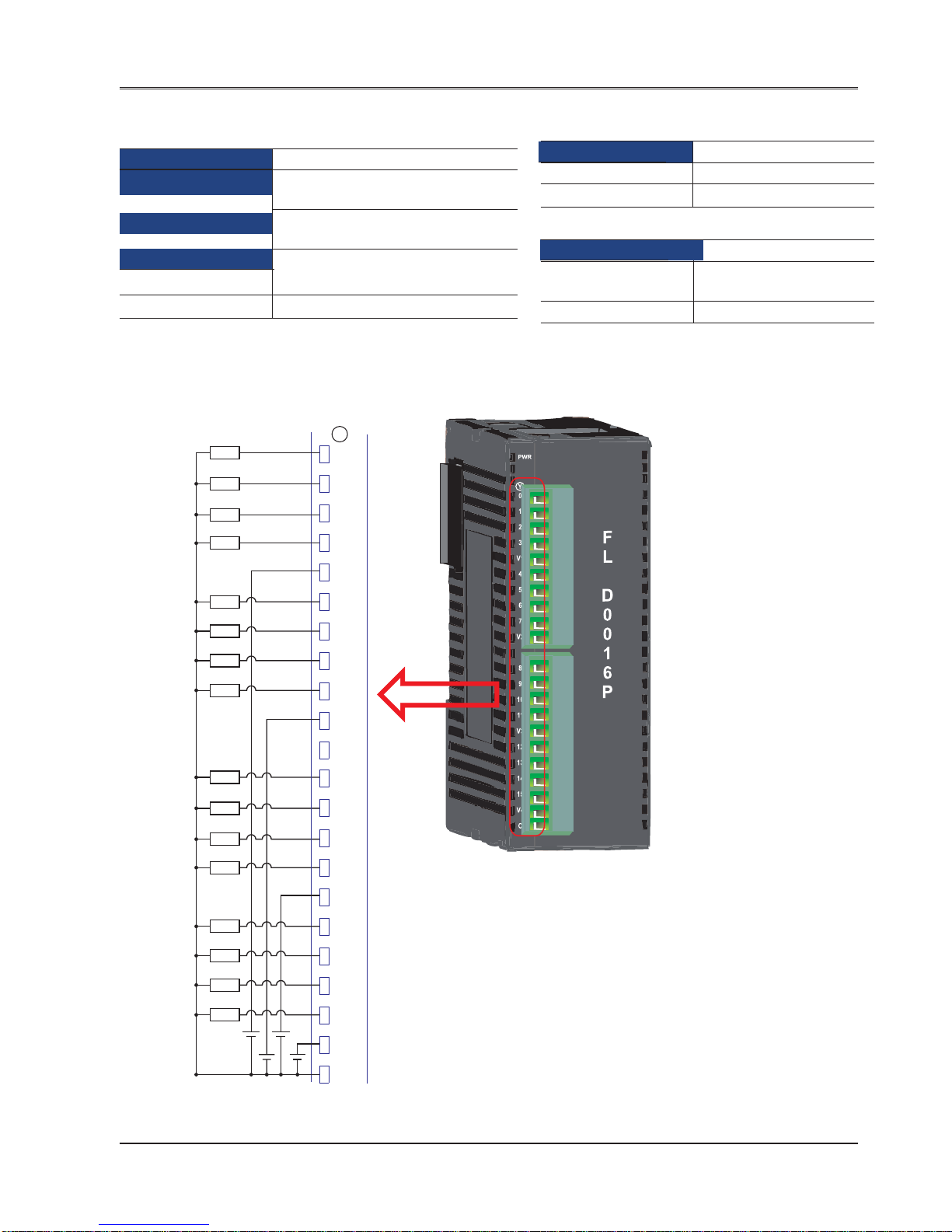
FLD0016P (PNP Type transistor output)
Digital Inputs 0
Digital outputs 16 PNP type Transistor output. 4
points per common
Rated load 500mA max for PNP and NPN type
transistor output
General
Mechanical Dimension 100mm X 35mm X 70mm
Weight Approx. 120 gm.
Wiring Diagram for FLD0016P
Y
0
1
2
3
V1
4
5
6
7
V2
L
L
L
L
L
L
L
L
8
9
10
11
V3
12
13
14
15
V4
C
+
+
-
L
L
L
L
L
L
L
L
+
-
+
Power Rating (Back Plane)
Voltage Rating 3.75 VDC derived from
base model
Current Rating Upto 80mA
Power Supply 24VDC, 300mA
Input per channel NA
Output per channel 0.5A, 24VDC per output
Introduction
32
Doc No: UMAN\FL\01 10
Rev . No.: 1.02B
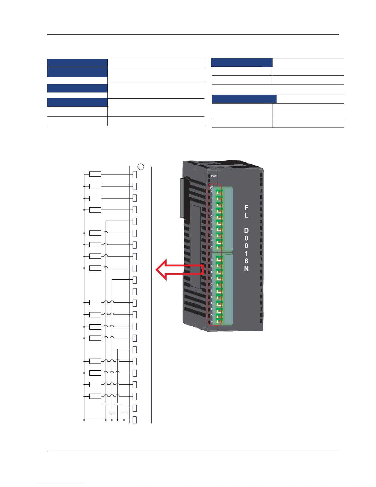
FLD0016N (NPN Type transistor output)
Digital Inputs 0
Digital outputs 16 NPN type Transistor output. 4
points per common
Rated load 500mA max for PNP and NPN type
transistor output
General
Mechanical Dimension 100mm X 35mm X 70mm
Weight Approx. 120 gm.
Wiring Diagram for FLD0016N
Y
0
1
2
3
C1
4
5
6
7
C2
L
L
L
L
L
L
L
L
8
9
10
11
C3
12
13
14
15
C4
+
+
-
+
-
L
L
L
L
L
L
L
L
+
-
+
-
Power Rating (Back Plane)
Voltage Rating 3.75 VDC derived from
base model
Current Rating Upto 80mA
Power Supply 24VDC, 300mA
Input per channel NA
Output per channel 0.5A, 24VDC per output

Introduction
33
Doc No: UMAN\FL\01 10
Rev . No.: 1.02B
FLD0016R (Relay Type output)
Digital Inputs 0
Digital outputs 16 Relay (Form A) output. 4
points per common
Rated load 230V / 2A, 30VDC / 2A
General
Mechanical Dimension 100mm X 35mm X 70mm
Weight Approx. 180 gm.
Wiring Diagram for FLD0016R
Power Rating (Back Plane)
Voltage Rating 3.75 VDC derived from
base model
Current Rating Upto 80mA
Power Supply 24VDC, 300mA
Input per channel NA
Output per channel 230V, 2A / 30 VDC, 2A per
output
Y
0
1
2
3
C1
4
5
6
7
C2
8
9
10
11
C3
12
13
14
15
C4
L2
L4
L1
230 VAC
P
N
L3
L6
L8
L5
230 VAC
P
N
L7
L10
L12
L9
230 VAC
P
N
L11
L14
L16
L13
230 VAC
P
N
L15
*L1 to L16 are A.C. Load.

Introduction
34
Doc No: UMAN\FL\01 10
Rev . No.: 1.02B
Digital Inputs 8 Normal inputs 4 points per common.
Bidirectional type.
Digital outputs 8 Relay (Form A) outputs. 4 points per
common.
8 PNP type Transistor output. 4 points per
common.
8 NPN type Transistor output. 4 points per
common.
Rated Input voltage 24VDC
Rated Input Current Upto 5mA
Input Impedance 5.4K ohm
Minimum ON voltage 9.6 VDC
Maximum OFF voltage 3.6 VDC
Turn ON time 10 msec
Turn OFF time 10 msec
Isolation Optically isolated from the internal circuit
Connection method Removable terminals (3.81mm pitch)
Output Capacity 2A per o/p. 8A per common for Relay type
output
500mA max for PNP and NPN type
transistor output
Rated load 230V / 2A, 30VDC / 2A (for Relay),
500mA at 24VDC (for transistor)
General
Operating Temperature 0 to 55 deg.C.
Storage Temperature -20 to 85 deg.C.
Operating Humidity 10% to 90% (Non condensing)
Vibration 10Hz to 150Hz ,displacement of 0.2 mm
(peak) (3 mutually perpendicular axes)
Shock 490.5 m/s2,2 half-sine shocks per axis,
on 3 mutually perpendicular axes)
Mechanical Dimension 100mm X 35mm X 70mm
Weight For FLD0808N and FLD0808P:
Approx. 120 gm.
For FLD0808R: Approx. 160gm
FTB IEC61000-4-4 [2.2kV (Power- Direct
(Fast Transient / Burst) Injection), 1.2KV (I/O - Capacitive clamp).]
Electrostatic discharge IEC61000-4-2 Level 3
Electromagnetic field IEC61000-4-3, 10 V/m AM modulation
(80 MHz to 1 GHz)
RF Immunity IEC61000-4-6, 10 V/m AM modulation
(0.15MHz to 80 MHz)
Dumped Oscillatory wave IEC61000-4-12
Surge Immunity IEC61000-4-5 Level 2
Radiated emission EN50081-2
FLD0808R (Relay Type transistor output)
FLD0808P (PNP Type transistor output)
FLD0808N (NPN Type transistor output)
Power Rating (Back Plane)
Voltage Rating 3.75 VDC derived from
base model
Current Rating Upto 80mA
Power Supply: 24VDC, 50mA
100mA for relay coil supply
Input per channel: 24VDC, 5mA
Output per channel: 0.5 A, 24VDC and
For FLD0808R: 230V, 2A /
24VDC, 2A
Introduction
35
Doc No: UMAN\FL\01 10
Rev . No.: 1.02B
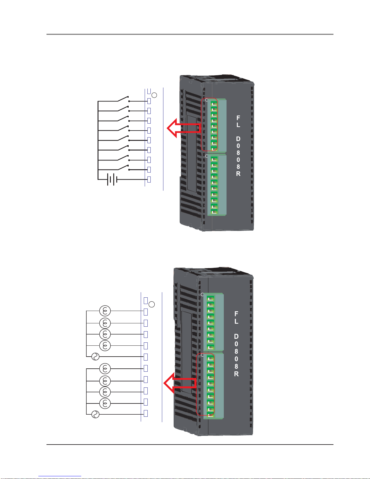
Wiring Diagram for FLD0808R:
1. Wiring diagram for testing digital inputs:
2. Wiring diagram for output connections:
X0
X1
X2
X3
X4
X5
X6
X7
24VDC
+
-
SW1
SW2
SW3
SW4
SW5
SW6
SW7
SW8
C
X
0
1
2
3
4
5
6
7
C
X
0
1
2
3
4
5
6
7
C
Y
PWR
0
1
2
3
C1
4
5
6
7
C2
Closing Swx will turn on respective inputs
X
0
1
2
3
4
5
6
7
C
Y
PWR
0
1
2
3
C1
4
5
6
7
C2
*L1 to L8 are A.C. Load.
Y
0
1
2
3
C1
4
5
6
7
C2
L2
L4
L1
230 VAC
P
N
L3
L6
L8
L5
230 VAC
P
N
L7

Introduction
36
Doc No: UMAN\FL\01 10
Rev . No.: 1.02B
Wiring Diagram for FLD0808P:
1. Wiring diagram for testing digital inputs:
2. Wiring diagram for output connections:
Y
0
1
2
3
V1
4
5
6
7
V2
C
+
+
-
L
L
L
L
L
L
L
L
24VDC
+
-
X0
X1
X2
X3
X4
X5
X6
X7
SW1
SW2
SW3
SW4
SW5
SW6
SW7
SW8
C
X
0
1
2
3
4
5
6
7
C
Closing Swx will turn on respective inputs
+
-

Introduction
37
Doc No: UMAN\FL\01 10
Rev . No.: 1.02B
Wiring Diagram for FLD0808N:
1. Wiring diagram for testing digital inputs:
2. Wiring diagram for output connections:
Closing Swx will turn on respective inputs
X0
X1
X2
X3
X4
X5
X6
X7
24VDC
+
-
SW1
SW2
SW3
SW4
SW5
SW6
SW7
SW8
C
X
0
1
2
3
4
5
6
7
C
Y
0
1
2
3
C1
4
5
6
7
C2
+
+
-
+
-
L
L
L
L
L
L
L
L

Introduction
38
Doc No: UMAN\FL\01 10
Rev . No.: 1.02B
FLA0800L
Analog Inputs 8 input channels
Volt age Input 0 - 10 V
Current Input 4- 20 mA
Analog Outputs 0
Isolation Isolation between analog and
digital section. No
interchannel isolation. Power
supply is isolated
Connection method Removable terminals
(3.81mm pitch)
Resolution 16 Bit
Accuracy 0.2 % of Full Scale
Nonlinearity 0.04% Max.
Input Impedence 470K ohm (voltage mode)
100 ohm (Current mode)
Temperatur Drift 60 ppm
General
Operating Temperature 0 to 55 Degree.
Storage Temperature (-20) to 85 deg.C.
Operating Humidity 10 to 90 %
(Non condensing)
Vibration 10Hz to 150Hz ,displace-
ment of 0.2 mm (peak) (3
mutually perpendicular
axes)
Shock 490.5 m/s2,2 half-sine
shocks per axis, on 3
mutually perpendicular
axes)
Mechanical Dimension 100mm X 35mm X 70mm
Weight Approx. 155 gm.
FTB IEC61000-4-4 [2.2kV (Fast
Transient / Burst) (Power- Direct Injection),
1.2KV (I/O - Capacitive
clamp).]
Electrostatic discharge IEC61000-4-2 Level 3
Electromagnetic field IEC61000-4-3, 10 V/m AM
modulation (80 MHz to 1 GHz)
RF Immunity IEC61000-4-6, 10 V/m AM
modulation (0.15MHz to 80
MHz)
Dumped Oscillatory wave IEC61000-4-12
Surge Immunity IEC61000-4-5 Level 2
Radiated emission EN50081-2
PWR
F
L
A
0
8
0
0
L
AIN1
AIN2
AIN3
AIN4
AGND
AGND
AGND
AGND
AGND
AGND
AGND
AGND
AIN5
AIN6
AIN7
AIN8
Power Rating (Back Plane)
Digital Side: Power derived from expansion slot connector
Voltage Rating 3.75 VDC derived from
base model
Current Rating Upto 80mA
Power Supply: 24VDC, 100mA
Introduction
39
Doc No: UMAN\FL\01 10
Rev . No.: 1.02B
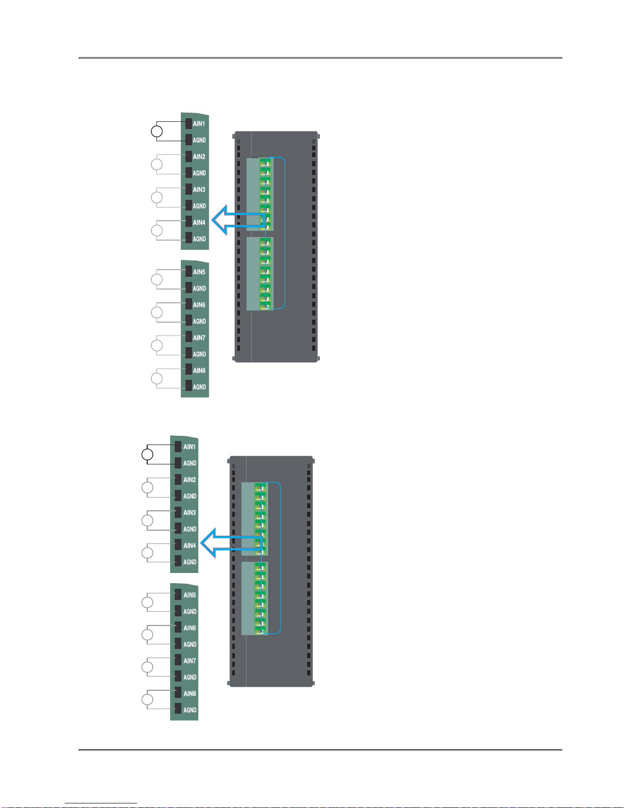
Wiring Diagram of input connection for FLA0800L:
1. Volt age Mode connections::
2. Current mode connections:
PWR
F
L
A
0
8
0
0
L
AIN1
AIN2
AIN3
AIN4
AGND
AGND
AGND
AGND
AGND
AGND
AGND
AGND
AIN5
AIN6
AIN7
AIN8
V
+
-
V
+
-
V
+
-
V
+
-
V
+
-
V
+
-
V
+
-
V
+
-
PWR
F
L
A
0
8
0
0
L
AIN1
AIN2
AIN3
AIN4
AGND
AGND
AGND
AGND
AGND
AGND
AGND
AGND
AIN5
AIN6
AIN7
AIN8
mA
+
-
4to20mA
mA
+
-
4to20mA
mA
+
-
4to20mA
mA
+
-
4to20mA
mA
+
-
4to20mA
mA
+
-
4to20mA
mA
+
-
4to20mA
mA
+
-
4to20mA
Introduction
40
Doc No: UMAN\FL\01 10
Rev . No.: 1.02B
FLA0800R
Analog Inputs 8 input channels
RTD PT100
Analog Outputs 0
Isolation Isolation between analog
and digital section. No
interchannel isolation.
Power supply is isolated
Connection method Removable terminals
(3.81mm pitch)
Resolution 16 Bit
Accuracy 0.2 % of Full Scale
Nonlinearity 0.04% Max.
Input Impedence 470K ohm (voltage mode)
100 ohm (Current mode)
Temperatur Drift 60 ppm
General
Operating Temperature 0 to 55 Degree.
Storage Temperature (-20) to 85 deg.C.
Operating Humidity 10 to 90 %
(Non condensing)
Vibration 10Hz to 150Hz ,displace-
ment of 0.2 mm (peak) (3
mutually perpendicular
axes)
Shock 490.5 m/s2,2 half-sine
shocks per axis, on 3
mutually perpendicular
axes)
Mechanical Dimension 100mm X 35mm X 70mm
Weight Approx. 155 gm.
FTB IEC61000-4-4 [2.2kV (Fast
Transient / Burst) (Power- Direct Injection),
1.2KV (I/O - Capacitive
clamp).]
Electrostatic discharge IEC61000-4-2 Level 3
Electromagnetic field IEC61000-4-3, 10 V/m AM
modulation (80 MHz to 1 GHz)
RF Immunity IEC61000-4-6, 10 V/m AM
modulation (0.15MHz to 80
MHz)
Dumped Oscillatory wave IEC61000-4-12
Surge Immunity IEC61000-4-5 Level 2
Radiated emission EN50081-2
Power Rating (Back Plane)
Digital Side: Power derived from expansion slot
connector
Voltage Rating 3.75 VDC derived from
base model
Current Rating Upto 80mA
Power Supply: 24VDC, 100mA
PWR
F
L
A
0
8
0
0
R
CS1
CS3
AIN1
AIN3
CS2
CS4
AIN2
AIN4
AGND
AGND
CS5
CS7
AIN5
AIN7
CS6
CS8
AIN6
AIN8
AGND
AGND
Introduction
41
Doc No: UMAN\FL\01 10
Rev . No.: 1.02B
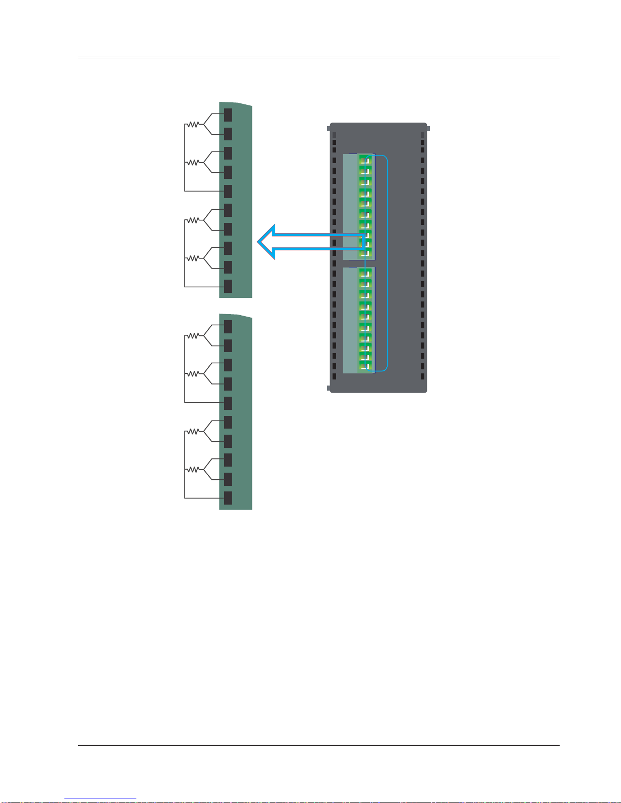
Wiring Diagram of input connection for FLA0800R:
PWR
F
L
A
0
8
0
0
R
CS1
CS3
AIN1
AIN3
CS2
CS4
AIN2
AIN4
AGND
AGND
CS5
CS7
AIN5
AIN7
CS6
CS8
AIN6
AIN8
AGND
AGND
RTD
PT1000
Note:
CSx: Current source(x equals to 1 to 8)
AINx: Analog input(x equals to 1 to 8)
AGND: Analog ground.Analog ground for
all channels is internally shorted on PCB
Connect RTD PT100 as shown in the above
diagram between the points CS, AIN and AGND
CS1
CS3
AIN1
AIN3
CS2
CS4
AIN2
AIN4
AGND
AGND
CS5
CS7
AIN5
AIN7
CS6
CS8
AIN6
AIN8
AGND
AGND
Input Channel 0
Input Channel 1
Input Channel 2
Input Channel 3
Input Channel 4
Input Channel 5
Input Channel 6
Input Channel 7

Introduction
42
Doc No: UMAN\FL\01 10
Rev . No.: 1.02B
FLA0004
Analog Inputs 0
Analog Outputs 4 Output channels
Voltage 0 - 10 V (Min Load 1000 ohm)
Current 4 - 20 mA(Max load 500 ohm)
Isolation Isolation between analog and digital
section. No interchannel isolation.
Power supply is isolated
Connection method Removable terminals (3.81mm pitch)
Resolution 16 Bit
Accuracy 0.2 % of Full Scale
Nonlinearity 0.04% Max.
General
Operating Temperature 0 to 55 Degree.
Storage Temperature (-20) to 85 deg.C.
Operating Humidity 10 to 90 % (Non condensing)
Vibration 10Hz to 150Hz ,displacement of
0.2 mm (peak) (3 mutually
perpendicular axes)
Shock 490.5 m/s2,2 half-sine shocks per
axis, on 3 mutually perpendicular
axes)
Mechanical Dimension 100mm X 35mm X 70mm
Weight Approx. 155 gm.
FTB IEC61000-4-4 [2.2kV (Power- Direct
(Fast Transient / Burst) Injection), 1.2KV (I/O - Capacitive
clamp).]
Electrostatic discharge IEC61000-4-2 Level 3
Electromagnetic field IEC61000-4-3, 10 V/m AM modulation
(80 MHz to 1 GHz)
RF Immunity IEC61000-4-6, 10 V/m AM modulation
(0.15MHz to 80 MHz)
Dumped Oscillatory wave IEC61000-4-12
Surge Immunity IEC61000-4-5 Level 2
Radiated emission EN50081-2
Power Rating (Back Plane)
Digital Side: Power derived from expansion slot
Voltage Rating 3.75 VDC derived from
base model
Current Rating Upto 80mA
Power Supply: 24VDC, 150mA
VO1
IO1
AGND
AGND
VO2
IO2
AGND
AGND
VO3
VO4
IO3
IO4
PWR
F
L
A
0
0
0
4
Introduction
43
Doc No: UMAN\FL\01 10
Rev . No.: 1.02B
Wiring Diagram of input connection for FLA0004:
1. Current Output Connection Diagram:
2. Voltage Output Connection Diagram:
VO1
IO1
AGND
AGND
VO2
IO2
AGND
AGND
VO3
VO4
IO3
IO4
PWR
F
L
A
0
0
0
4
VO1
IO1
AGND
AGND
VO2
IO2
AGND
AGND
VO3
VO4
IO3
IO4
Iout
Iout
Iout
Iout
VO1
IO1
AGND
AGND
VO2
IO2
AGND
AGND
VO3
VO4
IO3
IO4
PWR
F
L
A
0
0
0
4
Vout
VO1
IO1
AGND
AGND
VO2
IO2
AGND
AGND
VO3
VO4
IO3
IO4
Vout
Vout
Vout

Introduction
44
Doc No: UMAN\FL\01 10
Rev . No.: 1.02B
FLA0402U
Analog Inputs 4 Universal Input Channels
Volt age Input 0 - 10 V
Current Input 0-20mA, 4-20mA
RTD PT100 (alpha1, alpha2)
Thermocouple(TYPE
B,R,S,E,J,K,N,T.)
mV 0-100mV, 0-50 mV
Analog Outputs 2 Output channels
Voltage 0 - 10 V (Min Load 1000 ohm)
or
Current 4 - 20 mA (Max load 500 ohm)
Isolation Isolation between analog and digital
section. No interchannel isolation.
Power supply is isolated
Connection method Removable terminals (3.81mm pitch)
Resolution 16 Bit
Accuracy 0.2 % of Full Scale
Nonlinearity 0.04% Max.
Input Impedence 1Mohm (Voltage/mV/TC/RTD mode)
typically 30 ohm (Current mode)
Excitation Current for RTD 0.5 mA
General
Operating Temperature 0 to 55 Degree.
Storage Temperature (-20) to 85 deg.C.
Operating Humidity 10 to 90 % (Non condensing)
Vibration 10Hz to 150Hz ,displacement of 0.2
mm (peak) (3 mutually perpendicular
axes)
Shock 490.5 m/s2,2 half-sine shocks per
axis, on 3 mutually perpendicular
axes)
Mechanical Dimension 100mm X 35mm X 70mm
Weight Approx. 155 gm.
FTB IEC61000-4-4 [2.2kV (Power- Direct
(Fast Transient / Burst) Injection), 1.2KV (I/O - Capacitive
clamp).]
Electrostatic discharge IEC61000-4-2 Level 3
Electromagnetic field IEC61000-4-3, 10 V/m AM modulation
(80 MHz to 1 GHz)
RF Immunity IEC61000-4-6, 10 V/m AM modulation
(0.15MHz to 80 MHz)
Dumped Oscillatory wave IEC61000-4-12
Surge Immunity IEC61000-4-5 Level 2
Radiated emission EN50081-2
VO1
IO1
AGND
VO2
IO2
CS11
AGND
CS21
AGND
I1-
IN2+
IN1+
I2-
CS31
AGND
IN3+
CS41
AGND
IN4+
I3-
I4-
F
L
A
0
4
0
2
U
PWR
Power Rating (Back Plane)
Digital Side: Power derived from expansion slot
Voltage Rating 3.75 VDC derived from
base model
Current Rating Upto 80mA
Power Supply: 24VDC, 150mA

Introduction
45
Doc No: UMAN\FL\01 10
Rev . No.: 1.02B
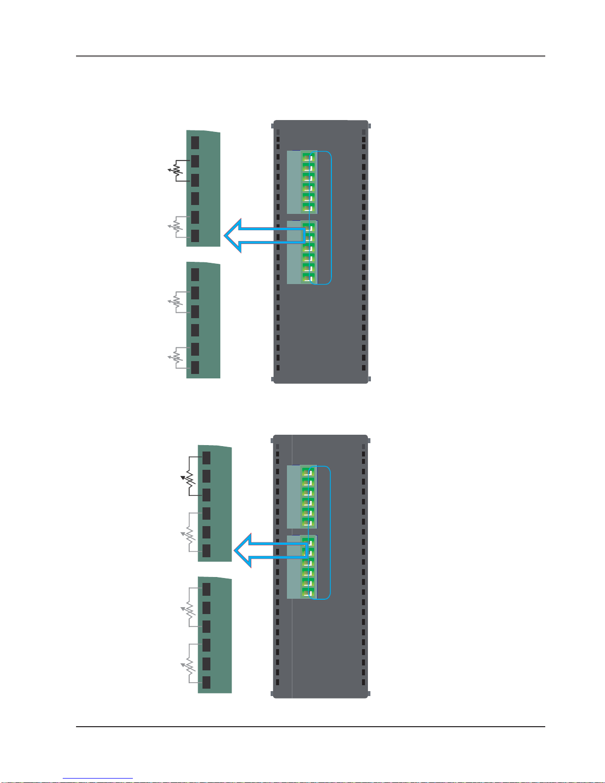
Wiring Diagram of input connection for FLA0402U:
1. Current Input Connection Diagram:
2. Voltage and mV Input Connection Diagram:
VO1
IO1
AGND
VO2
IO2
CS11
AGND
CS21
AGND
I1-
IN2+
IN1+
I2-
CS31
AGND
IN3+
CS41
AGND
IN4+
I3-
I4-
F
L
A
0
4
0
2
U
PWR
mA
Improper Connection for current:
mA
CURRENT
+
-
CS
IN+
AGND I-
CS11
AGND
CS21
AGND
I1-
IN2+
IN1+
I2-
CS31
AGND
IN3+
CS41
AGND
IN4+
I3-
I4-
+
-
+
-
mA
+
-
mA
+
-
mA
VO1
IO1
AGND
VO2
IO2
CS11
AGND
CS21
AGND
I1-
IN2+
IN1+
I2-
CS31
AGND
IN3+
CS41
AGND
IN4+
I3-
I4-
F
L
A
0
4
0
2
U
PWR
V/mV
+
-
CS11
AGND
CS21
AGND
I1-
IN2+
IN1+
I2-
CS31
AGND
IN3+
CS41
AGND
IN4+
I3-
I4-
V/mV
+
-
V/mV
+
-
V/mV
+
-

Introduction
46
Doc No: UMAN\FL\01 10
Rev . No.: 1.02B
3. RTD Input Connection Diagram:
4. Thermocouple Input Connection Diagram:
VO1
IO1
AGND
VO2
IO2
CS11
AGND
CS21
AGND
I1-
IN2+
IN1+
I2-
CS31
AGND
IN3+
CS41
AGND
IN4+
I3-
I4-
F
L
A
0
4
0
2
U
PWR
RTD
3 WIRE RTD
CS11
AGND
CS21
AGND
I1-
IN2+
IN1+
I2-
CS31
AGND
IN3+
CS41
AGND
IN4+
I3-
I4-
RTD
RTD
RTD
VO1
IO1
AGND
VO2
IO2
CS11
AGND
CS21
AGND
I1-
IN2+
IN1+
I2-
CS31
AGND
IN3+
CS41
AGND
IN4+
I3-
I4-
F
L
A
0
4
0
2
U
PWR
+
-
TC
CS11
AGND
CS21
AGND
I1-
IN2+
IN1+
I2-
CS31
AGND
IN3+
CS41
AGND
IN4+
I3-
I4-
+
-
TC
+
-
TC
+
-
TC

Introduction
47
Doc No: UMAN\FL\01 10
Rev . No.: 1.02B
Wiring Diagram of output connection for FLA0402U:
1. Current Output Connection Diagram:
2. Voltage Output Connection Diagram:
VO1
IO1
AGND
VO2
IO2
CS11
AGND
CS21
AGND
I1-
IN2+
IN1+
I2-
CS31
AGND
IN3+
CS41
AGND
IN4+
I3-
I4-
F
L
A
0
4
0
2
U
PWR
VO1
IO1
AGND
VO2
IO2
Iout
R < 500 Ω
VO1
IO1
AGND
VO2
IO2
CS11
AGND
CS21
AGND
I1-
IN2+
IN1+
I2-
CS31
AGND
IN3+
CS41
AGND
IN4+
I3-
I4-
F
L
A
0
4
0
2
U
PWR
Vout
VO1
IO1
AGND
VO2
IO2
R > 1000 Ω

Hardware
48
Doc No: UMAN\FL\01 10
Rev . No.: 1.02B
In this chapter. . . .
♦ Unpacking the unit
♦ Managing Electrostatic Discharge
♦ CE Compliance
♦ Environmental rating
♦ Environmental Consideration
♦ Safety Precautions
♦ Installation Instructions
♦ Wiring Diagram
♦ Communication Port
♦ Communication Cables
HARDWARE

Hardware
49
Doc No: UMAN\FL\01 10
Rev . No.: 1.02B
2.1 Unpacking The Unit
Carefully unpack the FlexiLogics unit. Please read all the instructions and cautions that appear on the shipping
container . Check that the container includes the Mounting DIN rail slider , locking connector , and a silica gel bag.
The silica gel bag is enclosed to absorb the moisture in the packing. Renu Electronics will not accept responsibility
for shortages against the packing list unless notified within 30 days. The unit and its accessories were inspected
and tested by Renu Electronics before shipment. All equipment should be in good working order . Examine the
product carefully and notify the carrier immediately if any shipping damage is evident. Y ou are responsible for claim
negotiations with the carrier. Save the shipping cont ainer and packing material in case the equipment needs to be
stored, returned to Renu Electronics, or transported for any reason.
2.2 Managing Electrostatic Discharge
It is recommanded NOT to remove the enclosure of the FlexiLogics unit. When any part of the enclosure is removed,
the circuitry inside is exposed to possible damage by electrostatic discharge during handling. Minimize the possibility of electrostatic discharge by:
• Dissipating static electricity of body prior to handling the FlexiLogics unit.
• Handling the FlexiLogics unit at a static-free grounded workstation.
• Connecting the frame ground connector of the FlexiLogics to a clean earth ground.
• Placing the FlexiLogics in an antistatic bag during transport.
2.3 CE Compliance
FlexiLogics products have been tested to confirm to European CE requirements per Council Directive. The European
Union created these requirements to ensure conformity among products traded in those countries. These products
are designed to withstand electrical noise in harsh industrial environment. They also confirm to requirements that
limit electrical emission. However this does not guarantee the products will be totally immune from possible malfunction in cases where severe electrical noise occurs. Therefore, we strongly recommend that you follow the
guidelines outlined for proper wiring and grounding to ensure the proper operation of the Renu products.
2.4 Environmental Consideration
FlexiLogics series models are designed to operate at temperature range defined in the specification. It is intended
primarily for indoor installations and may not be suitable for certain outdoor applications. A void installing the
FlexiLogics in environments with severe mechanical vibration or shocks. Do not install the FlexiLogics in enclosures
with rapid temperature variations or high humidity . Either will cause condensation of water inside the device and
eventual damage to the FlexiLogics unit.
Hardware
50
Doc No: UMAN\FL\01 10
Rev . No.: 1.02B
2.5 Safety Precaution
General Information:
1. FlexiLogics has been designed and manufactured for use in an industrial environment. However, the
FlexiLogics is not intended to be used for systems which may endanger human life. Consult REPL if you
intend to use the FlexiLogics for a special application, such as transportation machines, medical apparatus,
aviation and space systems, nuclear controls, submarine systems, etc.
2. The FlexiLogics has been manufactured under strict quality control. However , to keep safety of overall
automated system, fail-safe systems should be considered outside the FlexiLogics.
3. In installation, wiring, operation and maintenance of the FlexiLogics, it is assumed that the users have
general knowledge of industrial electric control systems. If this product is handled or operated improperly ,
electrical shock, fire or damage to this product could result.
4. This manual has been written for users who are familiar with Programmable Controllers and industrial
control equipment. Contact REPL if you have any questions about this manual.
Hazard Classifications:
In this manual, the following two hazard classifications are used to explain the safety precautions.
Indicates a potentially hazardous situation which, if not avoided, could result in death or
serious injury .
Indicates a potentially hazardous situation which, if not avoided, may result in minor or
moderate injury . It may also be used to alert against unsafe practices.
Even a precaution is classified as CAUTION, it may cause serious results depending on the situation. Observe all
the safety precautions described on this manual.
2.6 Installation Instruction
CAUTION
1. Excess temperature, humidity, vibration, shocks, or dusty and corrosive gas environment
can cause electrical shock, fire or malfunction. Install and use the FlexiLogics and related
equipment in the environment described in this manual.
2. Improper installation directions or insufficient installation can cause fire or the
units to drop. Install the FlexiLogics and related equipment in accordance with the
instructions described in this manual.
3. Turn off power before installing or removing any units, modules, racks or terminal blocks.
Failure to do so can cause electrical shock or damage to the FlexiLogics and related
equipment.
4. Entering wire scraps or other foreign debris into to the FlexiLogics and related equipment
can cause fire or malfunction. Pay attention to prevent entering them into the FlexiLogics
and related equipment during installation and wiring.
5. Turn off power immediately if the FlexiLogics or related equipment is emitting smoke or
odor. Operation under such situation can cause fire or electrical shock. Also unauthorized
repairing will cause fire or serious accidents. Do not attempt to repair . Contact REPL for
repairing.

Hardware
51
Doc No: UMAN\FL\01 10
Rev . No.: 1.02B
CAUTION
1. Turn off power before wiring to minimize the risk of electrical shock.
2. Exposed conductive parts of wire can cause electrical shock. Use crimp-style terminals
with insulating sheath or insulating tape to cover the conductive parts. Also close the
terminal covers securely on the terminal blocks when wiring has been completed.
3. Operation without grounding may cause electrical shock or malfunction. Connect the
ground terminal on the FlexiLogics to the system ground.
4. Applying excess power voltage to the FlexiLogics can cause explosion or fire. Apply power
of the specified ratings described in the manual.
5. Improper wiring can cause fire, electrical shock or malfunction. Observe local regulations on
wiring and grounding.
Wiring:

Hardware
52
Doc No: UMAN\FL\01 10
Rev . No.: 1.02B
2.7 Installation Instructions
The FlexiLogics should be mounted on a din rail plate. A din rail sliders and locking connectors are provided with
each FlexiLogics unit for proper installation.
Environmental Considerations:
Make sure that the unit is installed correctly and that the operating limits are followed (see S pecifications for
FlexiLogics). Do not operate the FlexiLogics in areas subject to explosion hazards due to flammable gases, vapors
or dusts. The FlexiLogics should not be installed where fast temperature variations are present. Highly humid areas
are also to be avoided. High humidity causes condensation of water in the unit.
Location Considerations:
Care should be taken when locating equipment behind the FlexiLogics to ensure that AC power wiring, PLC output
modules, contactors, starters, relays and any other source of electrical interference are located away from the
FlexiLogics. Particular care should be taken to locate variable speed drives and switching power supplies away from
the FlexiLogics.
Panel Mounting
This section presents the dimensional sketches and din rail sliding for FlexiLogics models.
(All dimensions are in mm and drawing are not to scale.)
2.7.1 Panel Mounting
FlexiLogics units are shipped with a DIN rail slider & locking connector attached to the unit. User can use the unit
with or without DIN rail slider.
Dimensional Details:

Hardware
53
Doc No: UMAN\FL\01 10
Rev . No.: 1.02B
FlexiLogics unit with DIN rail slider
Front View Rear View

Hardware
54
Doc No: UMAN\FL\01 10
Rev . No.: 1.02B
Step s to mount the unit on DIN rail plate
FIG-1 FIG-2 FIG-3
FIG-1 Pull up the sliders provided with the FlexiLogics towards outward direction.
FIG-2 Rest the unit on the DIN rail plate
FIG-3 Pull down the slider again so that unit can fix up with the DIN rail plate
Hardware
55
Doc No: UMAN\FL\01 10
Rev . No.: 1.02B
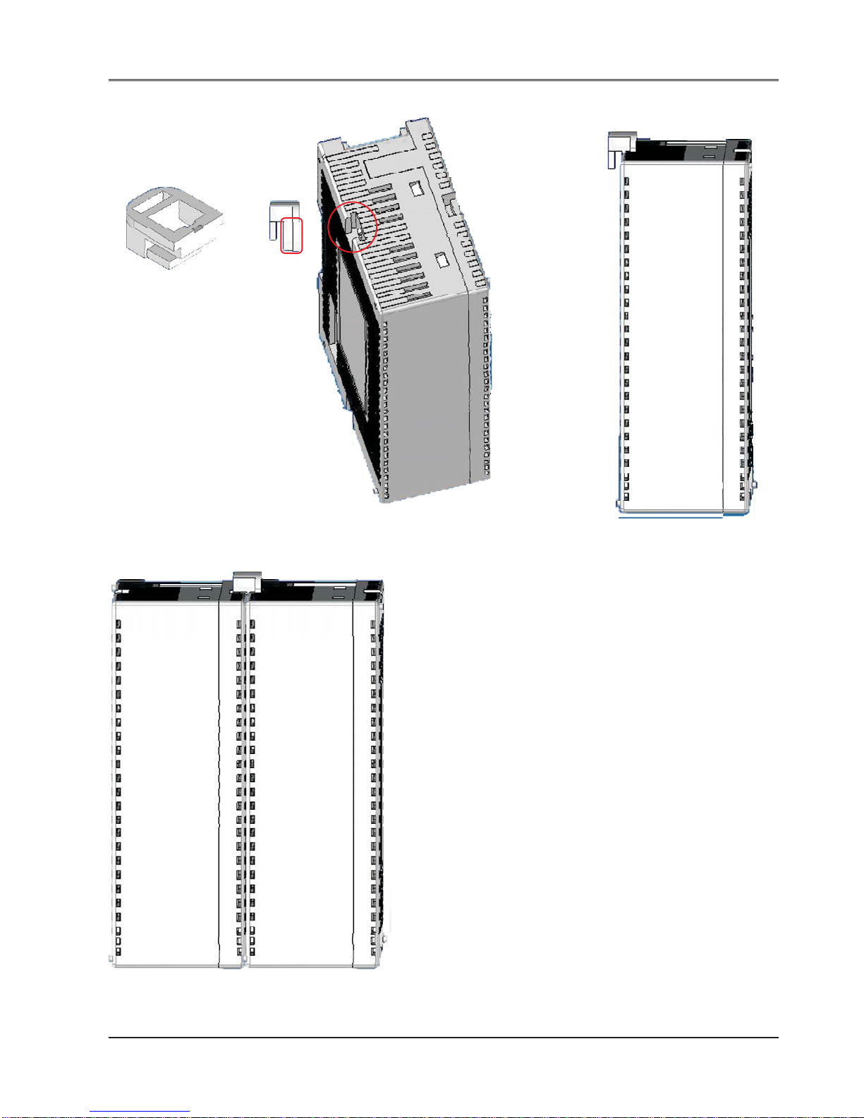
Step s to lock the expansion module with the FlexiLogics base
FIG-1 FIG-2 FIG-3
FIG-4
FIG-1 Lock connector provided with FlexiLogics unit
FIG-2 Two slots to grip the locking connector
are provided on the case highlighted by
RED circle. Insert a big leg of locking
connector highlighted by RED rectangle.
FIG-3 Single FlexiLogics unit with locking connector
FIG-4 Locking connector helps the two units
(FlexiLogics base & expansions)
to hold each-other properly on the DIN
rail plate along with DIN rail slider.
Note: Ap art from these lockings, also expansion connec-
tor is present to each FlexiLogics unit. User can connect
FlexiLogics base to expansion unit using this connector .
Also user can add more expansions to the unit with this
connector only.

Hardware
56
Doc No: UMAN\FL\01 10
Rev . No.: 1.02B
2.8 Wiring Diagram
If wiring is to be exposed to lightening or surges, use appropriate surge suppression devices. Keep AC, high energy
and rapidly switching DC wiring separate from signal wires.
Connecting high voltages or AC power mains to the DC input will make unit unusable and may create an electrical
shock hazard to personnel. Such a failure or shock could result in serious personal injury , loss of life and/or equipment damage. DC voltage sources should provide proper isolation from main AC power and similar hazards.
Pin description of the power connector for base (FL010 and FL050) models is as follows:
DC+ DC- Earth
24Vdc
123
2.9 Communication Ports
FlexiLogics communication ports support three types of serial communication.
They have two communication Ports in which COM1 is multi-signal port. Multi-Signal means COM1 port has RS232,
RS422, and RS485 signal levels.
A FlexiLogics can simultaneously communicate on both serial ports. The FlexiLogics can be programmed from a
PC on either port. Both ports can also be used with a serial printer .
Different cables are required to connect the FlexiLogics to a specific PLC. Cable details for any particular device are
given in the Operation Manual. The pin description of the communication ports for FlexiLogics model is as given
below:
1. COM1 Port Details:
Pin 1: 232TXD
Pin 2: 232RXD
Pin 3: GND
Pin 4: TX+
Pin 5: RX+
Pin 6: TX-
Pin 7: RX-
Pin 8: Reserved
R
H
F
L
0
1
0

Hardware
57
Doc No: UMAN\FL\01 10
Rev . No.: 1.02B
2. COM2 Port Details:
BATTERY
ABGNC
R
H
F
L
0
1
0
USB Device:
1. USB Device, compliant with USB 2.0 specification, self powered device.
2. Connector used: Standard USB T ype B Female connector.
Ethernet:
1. Fully compliant with IEEE 802.3 / 802.3u standards.
2. 10/100 Mbps support.
3. Connector used: St andard shielded RJ-45 female jack with in-built speed and link activity indica tion LEDs.

Hardware
58
Doc No: UMAN\FL\01 10
Rev . No.: 1.02B
2.10 Communication Cables
Programming cable for FlexiLogics units (IBM-H-005-00):
FlexiLogics SIDE
PC SIDE
2 mtr.
9
6
5
1
PC End
Pin 1
(Left side)
Pin 8
(Right side)
FRONT VIEW
R.H.S. VIEW
8 PIN MODULAR CONNECTOR
PINOUTS
DB9 FEMALE PINOUTS
Pin# Signals
1 TXD
2 RXD
3 SG & Shield
4
5
6
7
8
9
Signals Pin#
1
RXD 2
TXD 3
4
SG & Shield 5
6
7
8
9

Hardware
59
Doc No: UMAN\FL\01 10
Rev . No.: 1.02B
FlexiLogics TO T oshiba T1 PLC (RC-P-019A-00)
FlexiLogics TO T oshiba T2 PLC (RC-P-019B-00)
FlexiLogics TO GE 90/30 PLC (RC-P-002-00)
PIN SIGNALS
8P8C(RJ45) MALE PIN-OUTS
(Unit End)
8 Pin MINIDIN MALE PIN-OUTS
(PLC End)
TXD
18
RXD
26
GND
3 5 (Connect to shield )
short pin4&7atPLCend
PIN SIGNALS
8P8C(RJ45) MALE PIN-OUTS
(Unit End)
DB9 MALE PIN-OUTS
(PLC End)
TXD
12
RXD
23
GND
3 5 (Connect to shield )
Short 7&8atPLCEnd
(DB9 End)
PIN SIGNALS
8P8C(RJ45) MALE PIN-OUTS
(Unit End)
DB15 MALE PIN-OUTS
(PLC End)
TX+
411
13
10
12
7
1
RX+
RX-
5
TX-
6
7
GND
Shield connect only
plc End
3
Short 8 & 14 on PLC end
Short 6 & 15 on PLC end

Hardware
60
Doc No: UMAN\FL\01 10
Rev . No.: 1.02B
FlexiLogics TO Mitsubishi FX PLC (RC-P-008A-00)
FlexiLogics TO Aromat FP0 Series PLC (RC-P-015A-00)
FlexiLogics TO TSX 07 PLC (RC-P-026A-00)
PIN SIGNALS
8P8C(RJ45) MALE PIN-OUTS
(Unit End)
8 Pin MINIDIN MALE PIN-OUTS
(PLC End)
TX+
42
7
3
1
4
RX+
RX-
5
TX-
6
7
SG & SHIELD
3
PIN SIGNALS
8P8C(RJ45) MALE PIN-OUTS
(Unit End)
5 PIN MINIDIN MALE
PIN-OUTS (PLC End)
TXD
1
2
3
1
RXD
2
SG & SHIELD
3
PIN SIGNALS
8P8C(RJ45) MALE PIN-OUTS
(Unit End)
8 PIN MINIDIN MALE
PIN-OUTS (PLC End)
A
4&5
6&7
7
2
1
GND & SHIELD
B
3
FlexiLogics to A.B.Micrologix PLC(RC-P-027A-00)
PIN SIGNALS
8P8C(RJ45) MALE PIN-OUTS
(Unit End)
8 PIN MINIDIN MALE
PIN-OUTS (PLC End)
TXD
14
7
2
RXD
2
GND
(shield connect to
only PLC end)
3

Hardware
61
Doc No: UMAN\FL\01 10
Rev . No.: 1.02B
FlexiLogics to Microsmart PLC (RC-P-025B-00)
FlexiLogics TO TSX17 PLC (RC-P-017-00)
FlexiLogics TO LG MASTER-K Serise(RC-P-037-00)
PIN SIGNALS
8P8C(RJ45) MALE PIN-OUTS
(Unit End)
8 PIN MINIDIN MALE
PIN-OUTS (PLC End)
TXD
14
3
6&7
RXD
2
GND
(shield connect to
only PLC end)
3
PIN SIGNALS
8P8C(RJ45) MALE PIN-OUTS
(Unit End)
DB15 MALE PIN-OUTS
(PLC End)
A
4&5 14
7
5
8
Shield wire to DB15 pin no.8
only for PLC end
B
6&7
SHIELD
GND
3
PIN SIGNALS
8P8C(RJ45) MALE PIN-OUTS
(Unit End)
DB9 MALE PIN-OUTS
(PLC End)
TXD
RXD
12
3
5
5
Connect shield wire to PLC
end only.
2
SHIELD
GND
3
FlexiLogics TO Delta DVP PLC(RC-P-044-00)
PIN SIGNALS
8P8C(RJ45) MALE PIN-OUTS
(Unit End)
8 Pin MINIDIN MALE PIN-OUTS
(PLC End)
TXD
RXD
14
5
8
2
GND
(shield connect
to only PLC end)
3

Hardware
62
Doc No: UMAN\FL\01 10
Rev . No.: 1.02B
FlexiLogics TO OMRON CQM(RC-P-006B-00)
FlexiLogics TO Siemens Step-7 Micro PLC(RC-P-029-00)
PIN SIGNALS
8P8C(RJ45) MALE PIN-OUTS
(Unit End)
DB9 MALE PIN-OUTS
(PLC End)
TXD
RXD
1
2
3
9
1
Shield wire to DB9 pin no.1
only for PLC end
2
SHIELD
GND
3
PIN SIGNALS
8P8C(RJ45) MALE PIN-OUTS
(Unit End)
DB9 MALE PIN-OUTS
(PLC End)
A
SG
4&5
5
3
8
Shield wire to DB9 body only
for PLC End
3
B
6&7
FlexiLogics TO MPI (S7-300) PLC(RC-P-077-00)
PIN SIGNALS
8P8C(RJ45) MALE PIN-OUTS
(Unit End)
DB9 MALE PIN-OUTS
(PLC End)
A
B
4&5
5
3
8
Connect shield wire to DB9
(PLC end) only.
3
GND
6&7

Before you begin
63
Doc No: UMAN\FL\01 10
Rev . No.: 1.02B
In this chapter. . . .
♦ Installing FlexiSoft
♦ Starting FlexiSoft Configuration Sof tware
♦ Launching Ladder T ext Editor
♦ Creating Sample Ladder Application
BEFORE YOU BEGIN
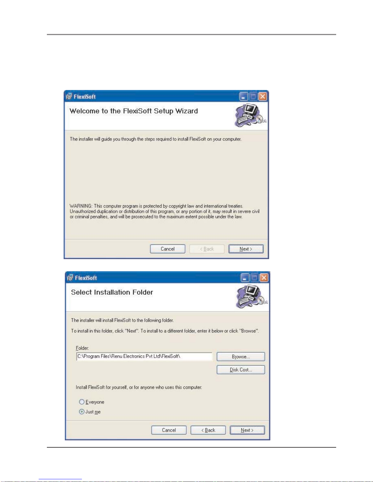
Before you begin
64
Doc No: UMAN\FL\01 10
Rev . No.: 1.02B
3.1 Installing FlexiSoft configuration software:
T o install FlexiSof t configuration Software:
1. Open Microsoft® Windows.
2. Select Run and Pop up window appears. Type the path for installing the Setup.
This will install FlexiSoft Configuration Setup Software.
3. When you click on OK, Welcome window appears on the screen. Click on Next.
4. Select the destination folder where setup will install the files.

Before you begin
65
Doc No: UMAN\FL\01 10
Rev . No.: 1.02B
5. Click on “NEXT”, installation starts. A dialog box indicating the status of progress of installation will display.
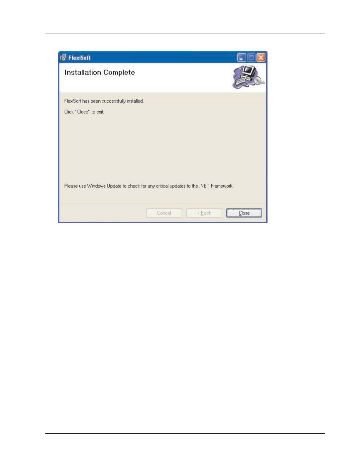
Before you begin
66
Doc No: UMAN\FL\01 10
Rev . No.: 1.02B
6. A screen is displayed to inform you when installation is completed.
This procedure installs FlexiSoft Software in start menu (in selected folder).
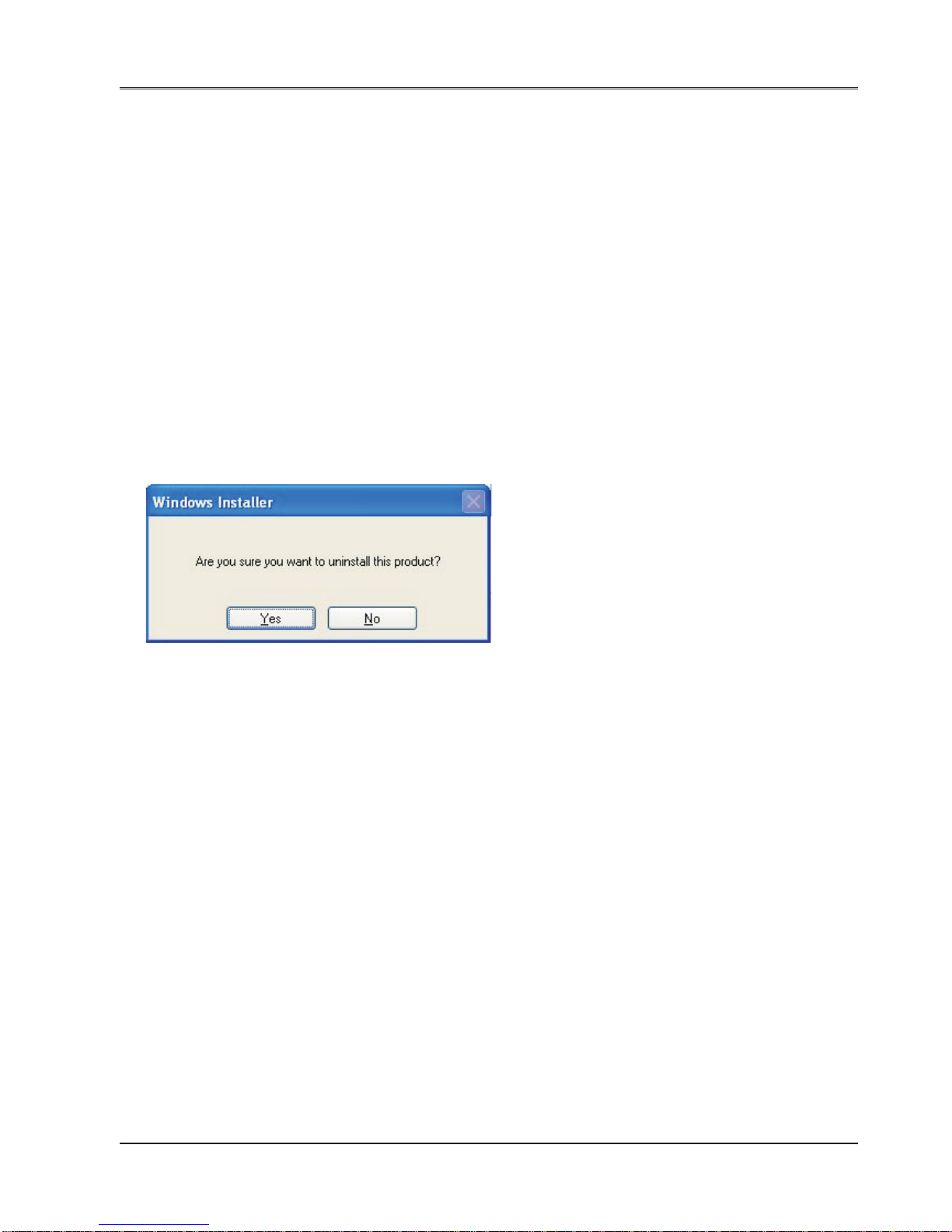
Before you begin
67
Doc No: UMAN\FL\01 10
Rev . No.: 1.02B
3.2 Steps for starting FlexiSoft Software
1. Click the Start button in Windows OS.
2. Select Programs.
3. Select “FlexiSoft”.
4. Select FlexiSoft setup exe.
5. Select New Application either from T ool st ation or from File Menu.
6. Select the model and product type that you would like to set by clicking on picture of the product in the
list.
7. Define the Unit Settings.
8. Next step is to define Tag Dat abase to your application.
3.3 Uninstalling FlexiSoft Software
1. In Windows click the Start button.
2. Select Programs.
3. Select FlexiSoft.
4. Select Uninstall FlexiSoft.
Following screen will display . The screen will ask you for the confirmation for uninstalling FlexiSoft configuration
software.

Before you begin
68
Doc No: UMAN\FL\01 10
Rev . No.: 1.02B
3.4 Procedure to launch ladder in FlexiSoft
Launch FlexiSoft setup software on your PC. Below shown welcome screen will display .
T o launch a ladder application either choose Project -> New option or click on New application icon.
Choose FlexiLogics unit and define “Project Configuration” window with the information required.
Click “OK”.
This will launch ladder editor to create an application as shown:

Before you begin
69
Doc No: UMAN\FL\01 10
Rev . No.: 1.02B
A ladder T ext Editor appears as shown below:
Now here you can create your ladder
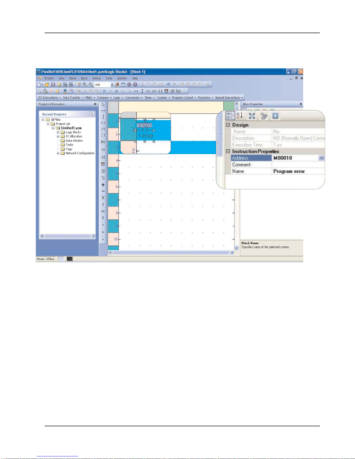
Before you begin
70
Doc No: UMAN\FL\01 10
Rev . No.: 1.02B
3.5 Creating sample ladder
After launching Ladder Text Editor, you can create a ladder here. S teps are shown below:
Step-1:
Here in the example, “NO” instruction is taken. Define its address and name from the “Instruction Properties” window
seen to the left side of the application window. as shown in the above figure.

Before you begin
71
Doc No: UMAN\FL\01 10
Rev . No.: 1.02B
Complete the rail using “Horizontal Link” command, then put “Output” command.
User can also directly put “Output” link to the last right side point of the rail. This will complete the command. as
shown below:
For output command also, define tag address and name from the “Instruction Properties” window seen to the right
side of the application window.
Put “End” instruction as shown below:
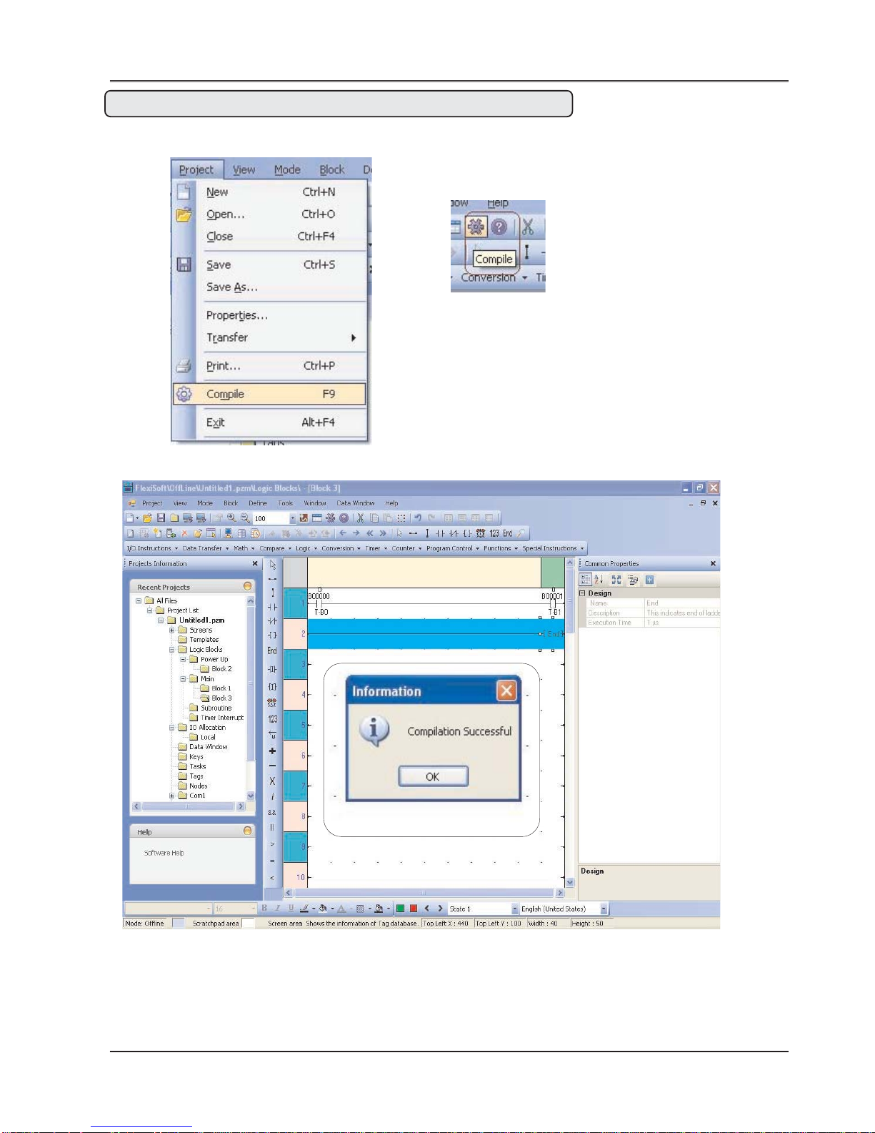
Before you begin
72
Doc No: UMAN\FL\01 10
Rev . No.: 1.02B
Note: Do not forget to put “END” command whenever ladder application is over.
After completing ladder, Compile it as shown below:
Following screen will appears if compilation is successful.
Or

Configuration
73
Doc No: UMAN\FL\01 10
Rev . No.: 1.02B
In this chapter. . . .
♦ Configuring unit using FlexiSoft
♦ T ag Database
♦ Memory Allocation of Registers
CONFIGURATION

Configuration
74
Doc No: UMAN\FL\01 10
Rev . No.: 1.02B
4.1 Configuring unit using FlexiSoft
Before creating any application or connecting FlexiLogics base unit to any system, user have to configure the
unit unsing FlexiSoft.
1. Connect the unit to the PC.
2. Power-On the unit.
3. Launch FlexiSoft software. “Welcome” screen will seen. Press “New” from the application window or
Project -> New as shown below:
4. This will launch “Select Product” window as shown below . Select the product and the model from the listing.
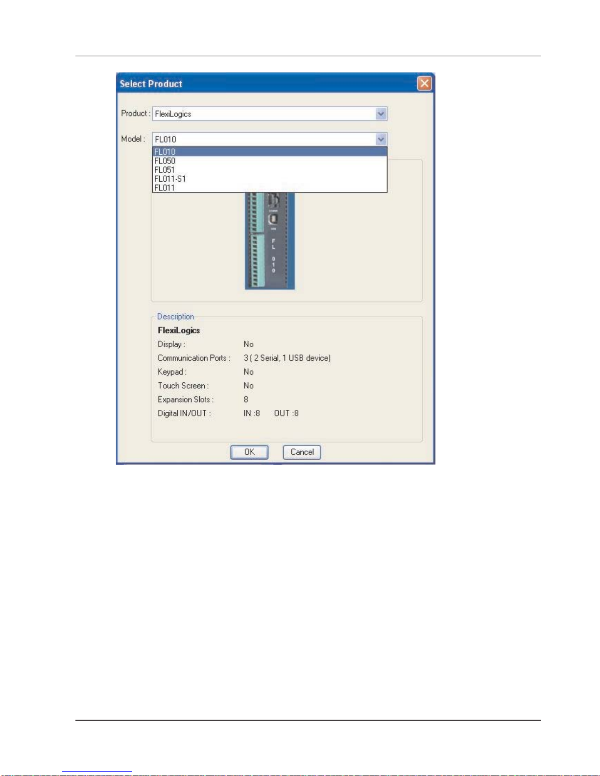
Configuration
75
Doc No: UMAN\FL\01 10
Rev . No.: 1.02B
5. Press “OK”. “Project Configuration” window will pop-up as shown below:

Configuration
76
Doc No: UMAN\FL\01 10
Rev . No.: 1.02B
1
2
3
4
5
6
7
In this dialoge box section:
Point 1: Y ou can define project name or can keep “Untitle” as default.
Point 2: Y ou can define p ath for the project to be saved.
Point 3: You can mention any special note; if required.
Point 4: Y ou can define author name.
Point 5: Y ou can define “password” for the project you created.
Point 6: You can see the information of the model selected.
Point 7: You can see the image of the model you selected.
Note: Point 6 and 7 will appear with all tabs of “Project Configuration” docker .
3. Press “OK” button.
Y ou can see a application window listing information as Logic blocks, tasks, t ags and Network Configuration.
After setting macro level parameters from these project items, your application is ready for downloading.

Configuration
77
Doc No: UMAN\FL\01 10
Rev . No.: 1.02B
4.2 Tag Database
This is the central database for the tags that need to be used in the application. Once the tags are defined (as
register or coils) and their attributes selected, the tags can be used in the application, tasks, etc. This screen
helps you to define Tags associated with defined Nodes. A tag is a register , coil or an individual bit of a register .
Select the type of tag from the Tag Type field.
If the type of tag selected is a register then the number of bytes required can also be selected. For editing a
floating point data number , the number of bytes must be 4. The Tag Name field is user definable. A tag is not
added to the tag list unless a tag name is defined. Once these fields are defined, click on the Add button. The
Block field in the tag database defines the starting address of the tag block followed by the block size.
For example : Tag M0214 is within a block ( M0214 : 1 ) whose starting address is M0214 and block size is 1.
This block size is optimized automatically depending on the address of PLC Tag.
Default block size is either 1 or 16. This setting varies from PLC to PLC.
The attributes of existing tag can be changed by highlighting the tag, making the changes, and clicking the
Change Tag button. An existing tag can be removed from tag list by clicking on Delete Tag button. Note that
removal of tags is possible only if they are not used in any application.
Add - Use this button to add a tag. Af ter clicking this button, the user has to define the following:
1. Node : Where the tag is located.
2. Register, coil or a bit within a register . Registers can be read only or read/write.
3. The address limits are shown and vary from PLC model to model.
4. Tag name : Each tag needs to have a unique name. The name can be up to 40 characters in length.
5. Byte(s) : If the selected tag is a register , the tag can be defined as a 1 byte ( either high or low byte), a 2
byte, or a 4 byte tag.
Edit – Select the tag. Edit the information and then click on the Update button.
Delete - Select the tag and click on Delete button to delete the tag. Before deleting any tag, the user must
delete any references to the tag in tasks. Otherwise it can not be deleted.

Configuration
78
Doc No: UMAN\FL\01 10
Rev . No.: 1.02B
Default System Tags
Note: Please do not attempt to modify read only system tags in the ladder . This could affect the functionality of
the product.
System Registers / Coils:
Register / Coil T a g Name Read / Write Description
SW0003_14 COM1 Status Rea d Only 0 = Communication Error; 1= Communicating
with PLC
SW0003_15 COM2 Status Rea d Only 0 = Communication Error; 1= Communicating
with PLC
S00 00 Carry Bit Read/Write Overflow indication in math operations of ladder
and also used in rotate with carry instruction.
SW0010 RTC Day of Month Read only RTC day in integer format
SW0011 RTC Month Read only RTC month in integer format
SW0012 RTC Yea r Read only RTC year in integer format
SW0013 RTC Hour Read only RTC hour in integer format
SW0014 RTC Min Read only RTC minute in integer format
SW0015 RTC Sec Read only RTC sec in integer format
SW0016 RTC Day of Week Read only RTC day of week in integer format
SW0017 Scan time register Read only Valu is in multiple of 0.1 mSec. This includes
execution time for reading inputs, executing
tasks, executing ladder , update outputs, etc.
(Refer flow chart)
S0019 Invalid RTC date entry Read only 0=valid date 1= Invalid date
SW0018 COM1 failed node reconnect Read/write Shows time in sec recover the communication
time (Sec) with failed nodes for port1.the default value is
60Sec
SW0019 COM2 failed node reconnect Read/write Shows time in sec recover the communication
time (Sec) with failed nodes for port1.the default value is
60Sec
SW022 COM3 failed node reconnect Read/write Shows time in sec recover the communication
time (Sec) with failed nodes for port3.the default value is
60Sec
S002 1 COM1 failed node reconnect Read/write If this bit is set communication with the failed
control nodes is detected after scan time SW0018 for
port1.By default : ON
S002 2 COM2 failed node reconnect Read/write If this bit is set communication with the failed
control nodes is detected after scan time SW0019 for
port2.By default : ON
S00 23 COM3 failed node reconnect Read/write If this bit is set communication with the failed
control nodes is detected after scan time SW0022 for
port3.By default : ON
SW64-SW65 Node Status Registers for Read only Shows the status of the node, whether node is
COM1 present or not. T otal 2 word Register are mapped
for 32 nodes.
SW80-SW81 Node Status Registers for Read only Shows the status of the node, whether node is
COM2 present or not. T ot al 2 word Register are
mapped for 32 nodes.
SW96-SW1 11 Node Status Registers for Read only Shows the status of the node, whether node is
COM3 present or not. T otal 16 word Register are
mapped for 256 nodes.
(Not applicable for FL010 and FL011)

Configuration
79
Doc No: UMAN\FL\01 10
Rev . No.: 1.02B
SW046 Ladder Scan Time Read only Value is multiple of 0.1 mSec
S003 4 Ladder Instruction Error Read/Write Set if Division by zero operation is performed in
Status the ladder instruction and for invalid conditions or
operands in case of conversion instructions.
Configuration Words and coils
Register / Coil T a g Name Read / Write Description
MW0000 PLC Operation Mode Read/Write Bit0-3: 0: Initialization 1: HALT Mode 2: RUN
(Bit 0 to Bit 3) Mode 3: RUN-F Mode 4: HOLD Mode 6: ERROR
Mode.
MW0001 Error Register 1 Read Only Refer mapped coils M16 to M31
MW0002 Error Register 2 Read Only Refer mapped coils M32 to M47
MW0003 RUN/STOP Switch Control Read Only 1: HALT, 0: RUN. Only LSB is used. other bits (1
(Retentive) to 15) are not used.
MW0005 Digital Filter constant Read/Write Enabled when MW10 bit 16 is ON.
(0 to 15 mS)
MW0010 Configuration Register for Read/Write Refer S pecial input - output section
Special input s
MW001 1 Configuration Register for Read/Write Refer Special input - output section
PWM output
MW0012 Preset values for high Speed Read/Write Used to set the preset values for high speed
MW0013 Counter counter
MW0014
MW0015
MW0016 Count Values for high S peed Read/Write Preset count values of the high speed counters
MW0017 Counter are stored
MW0018
MW0019
MW0020 High Speed counter Read/Write Control flags for high speed counters
control flags
MW0021 Special output control flags Read/Write Refer S pecial input - output section
MW0022 Special Output Control Flags Read/Write Control flags for high speed counters
MW0023
MW0024 Special output Frequency Read/Write Refer Special input - output section
MW0025 Setting
MW0030 System Timer Coils Read On ly Refer mapped coils M00480 to M00487
MW0031 User Interrupt program Status Read Only Bit 0 for timer ,Bit 1 for IO1, Bit 2 for IO2. Refer
Flags mapped coils M496,M497 & M498
when MW10 bit 16 is ON.
MW0033 Unit IP Address Lo W ord Read Only Used for Ethernet Model
MW0034 Unit IP Address Hi Word Read On ly
MW0035 Unit Subnet Mask Address Re ad Only
Lo Word
MW0036 Unit Subnet Mask Address Re ad Only
Hi Word
MW0037 Unit Default Gateway Read Only
Lo Word
MW0038 Unit Default Gateway Read Only
Hi Word
M00016 CPU error Read Only ON at error state
M00017 I/O error Read Only ON at error state
M00018 Program error Read Only ON at error state. This group includes Laader
Scan time.

Configuration
80
Doc No: UMAN\FL\01 10
Rev . No.: 1.02B
M00021 Clock/calendar illegal Read Only ON when clock/calendar data is illegal
value warning
M00022 Retentive data invalid warning Read Only ON when retentive data in RAM are invalid
M00027 Watchdog timer error Read Only ON at error state
M00029 I/O mismatch error Read Only ON at error state
M00031 I/O communication error Read Only ON at error state
M00033 Ladder Scan time error Read Only ON when the scan time exceeds 200ms (default)
M00480 System timer coil for 0.1 Read Only Toggle at 50 % duty cycle
sec interval
M00481 System timer coil for 0.2 Read Only Toggle at 50 % duty cycle
sec interval
M00482 System timer coil for 0.4 Read Only Toggle at 50 % duty cycle
sec interval
M00483 System timer coil for 0.8 Read Only Toggle at 50 % duty cycle
sec interval
M00484 System timer coil for 1 Read Only Toggle at 50 % duty cycle
sec interval
M00485 System timer coil for 2 Read Only Toggle at 50 % duty cycle
sec interval
M00486 System timer coil for 4 Read Only Toggle at 50 % duty cycle
sec interval
M00487 System timer coil for 8 Read Only Toggle at 50 % duty cycle
sec interval
M00496 Timer interrupt ladder Read Only ON when Timer program is executing
execution status
M00497 IO1 interrupt execution status Read Only ON when IO1 program is executing
M00498 IO2 interrupt execution status Read Only ON when IO2 program is executing
M00512 ALWAYS ON Read Only This coil is always ON
M00513 ALWAYS OF F Read Only This coil is always OFF

Configuration
81
Doc No: UMAN\FL\01 10
Rev . No.: 1.02B
4.3 Input (XW), Output (YW) and configuration (MW) Register allocation
For Digital Expansion Models:
The Physical Inputs and Outputs in the Expansion modules are accessed using XW and YW registers respectively .
The digital inputs in the Digital Expansion Models are updated in the (Input) XW registers.
The expansion model may have XW or YW registers depending on availability of the physical input/outputs for that
model type. As given in Section 7.2 ‘Memory Allocation of XW, YW and MW’, dif ferent expansion models have
different number of XW , YW and MW memory assigned for them in the base model.
e.g. The digital expansion model FLD1600 has 1 XW register memory assigned for it.
There are no outputs so no YW memory . So the input condition of FLD1600 is read in Input Register XWxx00. Same
inputs are shown in the input coils Xxx000 to Xxx015. Here xx denotes the slot number in which the expansion
model is connected to FlexiLogics.
Similarly , outputs register for FLD0016R model is YWxx00. For FLD0808R model it has one XW and one YW , but
only 8 bits are used. Other bits are not used.
For Analog Expansion Models:
Analog Inputs and Outputs in the Analog Expansion models are accessed using XW and YW registers respectively.
The type of input channel is configured from configuration registers MW.
FLA0800L and FLA0800R:
Sr. No. Description Register T ype
1 Channel 1 Input Data XWxx00 R
2 Channel 2 Input Data XWxx01 R
3 Channel 3 Input Data XWxx02 R
4 Channel 4 Input Data XWxx03 R
5 Channel 5 Input Data XWxx04 R
6 Channel 6 Input Data XWxx05 R
7 Channel 7 Input Data XWxx06 R
8 Channel 8 Input Data XWxx07 R
9 Channel 1 T ype Select MWxx08 R/W
10 Channel 2 T ype Select MWxx12 R/W
1 1 Channel 3 T ype Select MWxx16 R/W
12 Channel 4 T ype Select MWxx20 R/W
13 Channel 5 T ype Select MWxx24 R/W
14 Channel 6 T ype Select MWxx28 R/W
15 Channel 7 T ype Select MWxx32 R/W
16 Channel 8 T ype Select MWxx36 R/W
17 Input Conversion Enable MWxx40 R/W
18 Reserved MWxx41 19 Reserved MWxx42 20 Reserved MWxx43 21 Reserved MWxx44 22 Reserved MWxx45 -

Configuration
82
Doc No: UMAN\FL\01 10
Rev . No.: 1.02B
FLA0402U:
Sr. No. Description Register Type
1 Input Channel 1 Data XWxx00 R
2 Input Channel 2 Data XWxx01 R
3 Input Channel 3 Data XWxx02 R
4 Input Channel 4 Data XWxx03 R
5 Output Channel 1 Data YWxx00 R/W
6 Output Channel 2 Data YWxx01 R/W
7 Input Channel 1 Type Select MWxx06 R/W
8 Input Channel 2 Type Select MWxx10 R/W
9 Input Channel 3 Type Select MWxx14 R/W
10 Input Channel 4 Type Select MWxx18 R/W
1 1 Output Channel 1 Type Select MWxx22 R/W
12 Output Channel 2 Type Select MWxx26 R/W
13 Input and Output Conversion MWxx30 R/W
Enable
14 Reserved MWxx31 15 Reserved MWxx32 16 Reserved MWxx33 17 Reserved MWxx34 18 Reserved MWxx35 -
FLA0004:
Sr. No. Description Register Ty pe
1 Output Channel 1 Data YWxx00 R/W
2 Output Channel 2 Data YWxx01 R/W
3 Output Channel 3 Data YWxx02 R/W
4 Output Channel 4 Data YWxx03 R/W
5 Output Channel 1 Type Select MWxx04 R/W
6 Output Channel 2 Type Select MWxx08 R/W
7 Output Channel 3 Type Select MWxx12 R/W
8 Output Channel 4 Type Select MWxx16 R/W
9 Output Conversion Enable MWxx20 R/W

Configuration
83
Doc No: UMAN\FL\01 10
Rev . No.: 1.02B
Channel Type Selection Values Table:
Use the following values in the Input and output channel type select register to configure the corresponding channel
to particular type.
e.g. If you want to configure the Input channel 3 of FLA0800L model as ( 0 – 10 V ) type, then move value 19 in
MWxx16 configuration register. Here xx digit al denotes the slot number in which the FLA0800L model is connected
to PLC. The Conversion Enable Flag should be one to start the conversion (A to D or D to A).
Input Channel T ype Value
Not Defined 0
mV( 0 - 100 mV ) 1
mV( 0 - 50 mV ) 3
mA( 0 - 20mA ) 5
mA( 4 - 20mA ) 7
Volt age ( 0 - 10V ) 19
Volt age ( 1 - 5V ) 20
RTD PT -100 (alpha1) 9
RTD PT -100 (alpha2) 10
RTD PT -1000 21
Thermocouple (B-Type) 1 1
Thermocouple (R-Type) 12
Thermocouple (S-Type) 13
Thermocouple (E-Type) 14
Thermocouple (J-Type) 15
Thermocouple (K-Type) 16
Thermocouple (N-Type) 17
Thermocouple (T-T ype) 18
Output Channel T ype Value
Not Defined 0
mA( 4 - 20mA ) 1
Volt age ( 0 - 10V ) 2

Special Input and Output
84
Doc No: UMAN\FL\01 10
Rev . No.: 1.02B
In this chapter. . . .
♦ Special I/O Function Overview
♦ Single Phase Counter
♦ Single Phase speed-counter
♦ Quadrature bi-pulse counter
♦ Interrupt input function
♦ Pulse Output Function
♦ PWM Output Function
SPECIAL INPUT AND OUTPUT

Special Input and Output
85
Doc No: UMAN\FL\01 10
Rev . No.: 1.02B
5.1 Special I/O Function overview
The FlexiLogics PLCs support the special I/O functions as listed below:
Function name Function summary Remarks
V ariable input filter constant Input filter constant (ON/OFF delay time) can be set by MW10 setting is
user program. The setting range is 0 to 15 ms necessary to use this
(1 ms units). Default value is 0 ms. This function is function.
applied for X000 to X007 (8 points as a block).
Single phase Counts the number of pulses of single phase pulse Only one among these 4
up-counter train. 2 channels of pulse input are available. The functions can be
countable pulse rate is up to 50 kHz for each channel. selected.
Channel 1 ..... X000 count input, X002 reset input MW10 is used to select
Channel 2 ..... X001 count input, X003 reset input the function.
High Single phase Counts the number of pulses in a specified sampling
Speed speedcounter time. The sampling time setting is 10 to 1000 ms (10
Counter ms units). 2 channels of pulse input are available. The
countable pulse rate is up to 50 kHz for each channel.
Channel 1 ..... X000 count input
Channel 2 ..... X001 count input
Quadrature Counts the 2-phase pulses whose phases are shifted
bi-pulse counter 90° each other. Counts up when phase A precedes,
and counts down when phase B precedes. The
countable pulse rate is up to 5 kHz.
Phase A ..... X000
Phase B ..... X001
Reset ......... X002
Interrupt input function Immediately activates the corresponding I/O interrupt
program when the interrupt input is changed from OFF
to ON (or ON to OFF). 2 points of interrupt input are
available.
X001 ..... Interrupt 1 (I/O interrupt program #1)
X002 ..... Interrupt 2 (I/O interrupt program #2)
Pulse output function Variable frequency pulse train can be output. The Either one between
available pulse rate is 50 Hz to 5 KHz (1Hz units) these 2 functions can
Y0 ..... CW or Pulse (PLS) be used.
Y1 ..... CCW or Direction (DIR) MW1 1 is used to select
the function.
PWM output function Variable duty cycle pulse train can be output. The
available ON duty setting is 0 to 100 % (1 % units).
Y0 ..... PWM output

Special Input and Output
86
Doc No: UMAN\FL\01 10
Rev . No.: 1.02B
5.2 High Speed Counter Design
Configuration Registers for Special Function Input s and PWM outputs:
Register Description Register Number
Configuration Register for Special inputs MW10
Configuration Register for PWM output MW1 1
Single Phase Counter
Set Value
Channel 1 MW12, MW13
Channel 2 MW14, MW15
Count V alue
Channel 1 MW16, MW17
Channel 2 MW18, MW19
Soft Gate (Device)
Channel 1 M 320
Channel 2 M 328
Interrupt Enable (Device)
Channel 1 M 322
Channel 2 M330
Count Preset (Device)
Channel 1 M323
Channel 2 M331
Single Phase Speed Counter
Sampling Time
Channel 1 MW12
Channel 2 MW14
Hold V alue
Channel 1 MW16, MW17
Channel 2 MW18, MW19
Soft Gate (Device)
Channel 1 M 320
Channel 2 M 328
Quadrature Bi Pulse
Comparision V alue1 MW12, MW13
Comparision V alue2 MW14, MW15
Count V alue MW16, MW17
Soft Gate (Device) M320
Interrupt Enable1 (Device) M322
Count Preset 1 (Device) M324
Interrupt Enable 2 (Device) M323
Count Preset 2 (Device) M325
Pulse Output Function
Pulse Enable Flag (Device) M336
Frequency Setting Register MW22, MW23
Frequency Setting Error Flag (Device) M191

Special Input and Output
87
Doc No: UMAN\FL\01 10
Rev . No.: 1.02B
The Mode selection is done through two registers as below.
Configuration Register 10 (High Speed Input): ( MW0010).
PWM Output Function
Pulse Enable Flag (Device) M336
Frequency Setting Register MW22, MW23
ON duty setting register MW24, MW25
pulse width error flag M189
On duty setting error flag M190
Frequency Setting Error Flag (Device) M191
FEDCBA9876543210
0000
000: Normal
001: Ch2INT
010: Ch2HSC
011: Quadrature
100: Ch2 Single
phase counter
000: Normal
001: Ch1INT
010: Ch1HSC
011: Quadrature
100: Ch1 Single
phase counter
0: INT1 Rising
1: INT1 Falling
0: INT2 Rising
1: INT2 Falling
Channel1 HSC (Adding Counter)
0: Single Phase Up Counter
1: Single Phase Down Counter
Channel2 HSC (Adding Counter)
0: Single Phase Up Counter
1: Single Phase Down Counter
Quadrature
00: 1X mode
01: 2X mode
10: 4X Mode
Reserved
0: Variable input filter disable
1: Variable input filter enable

Special Input and Output
88
Doc No: UMAN\FL\01 10
Rev . No.: 1.02B
Configuration Register 1 1 (Pulse / PWM Output): MW001 1
FEDCBA9876543210
0 0 0 0000000
Bit 0
< P-OUT and PWM master flag >
0: No use
1: Use
Bit1<P-OUT/PWMselection >
0: PWM
1: P-OUT
Bit 2 < PLS mode >
0: CW/CCW
1: Pulse/Direction (PLS/DIR)
P-OUT / PWM operation error flag
(These are not user setting items)
Bit D < PWM pulse width error >
0: Normal
1: Error
Bit E < PWM ON duty setting error >
0: Normal
1: Error
Bit F < Frequency setting error >
0: Normal
1: Error
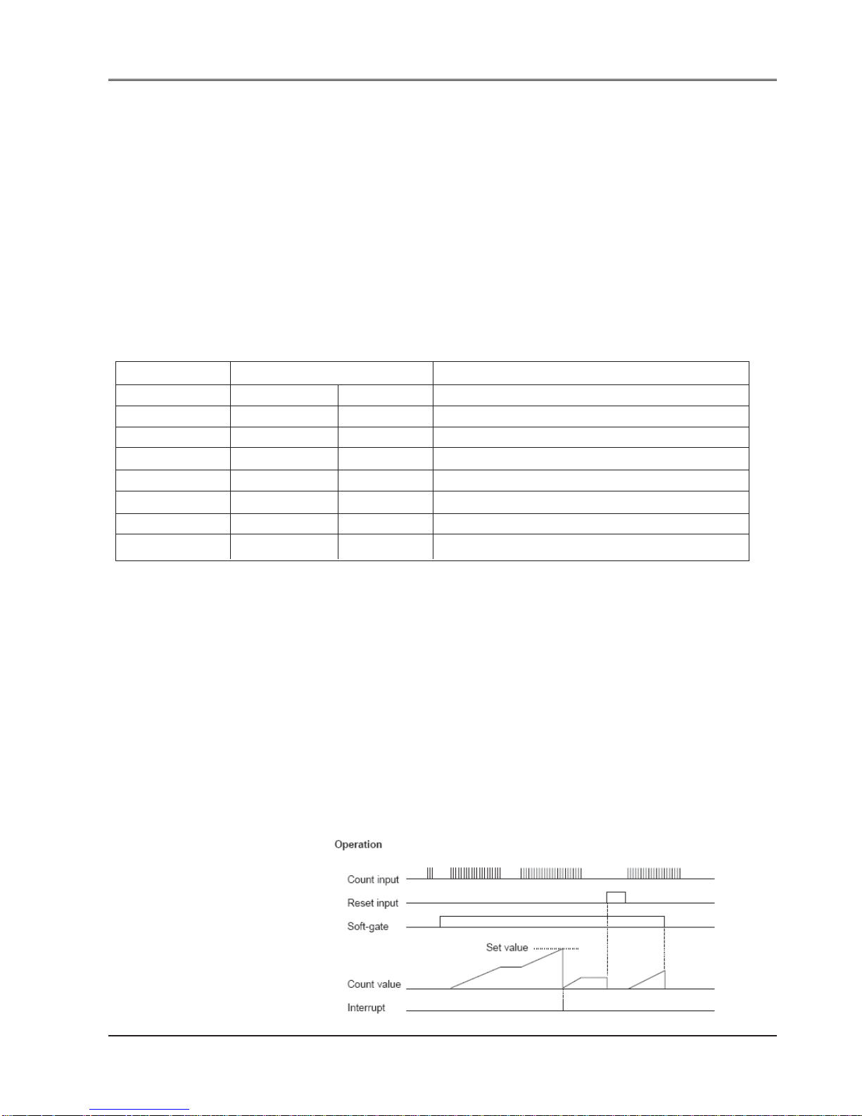
Special Input and Output
89
Doc No: UMAN\FL\01 10
Rev . No.: 1.02B
5.2.1 Single Phase Counter
When the count input is changed from OFF to ON, the count value is increased by 1. When the count value reaches
the set value, the count value is reset to 0, and I/O interrupt program is activated (if the interrupt enable flag is ON).
The count value is reset to 0 when the reset input comes ON. This counter operation is enabled while the soft-gate is
ON. The count value is reset to 0 when the soft-gate is changed from ON to OFF. The set value is set internally at
the timing of the soft-gate changing from OFF to ON. When the soft-gate is OFF, count value can be changed by
writing the data into the set value register and setting the count preset flag to ON. The count value range is H0000
0000 to HFFFF FFFF (32-bit data).
Hardware Condition:
Count input (IP 1 and IP 2) (X000 and X001)
ON/OFF pulse width: 10 micro or more (max. 50 kHz)
Reset input (X002 and X003)
ON/OFF duration: 2 ms or more
Related Registers:
Function Register/device Remarks
Channel 1 Channel 2
Count input IP 1 (X000) IP 2 (X001)
Reset input I P 3 (X002) IP 4 (X003)
Set value MW12 SW13 MW14 MW15 Data range: H0000 0000 to HFFFF FFFF
Count value MW16 MW17 MW18 MW19
Soft-gate M320 M328 Operation is enabled when ON
Interrupt enable M322 M330 Interrupt is enabled when ON
Count preset M323 M331 Used to preset the counter value
Note1:
When both the channels are configured in high speed mode, IP1 to IP4 cannot be used as normal input devices.
However, if either one channel is configured in high speed mode, the input s for other channel can be used as normal
input devices.
Note2:
T wo words are used for storing the double word (32bit) count/set values. Lower word will contain Lower 16bit value
and Higher word will contain higher 16 bit. This register storage scheme is applicable for all the modes.
value. Eg. Count value : MW16,MW17
So if count value is (Hex) 87654321
MW16 = 4321 (Hex)
MW17= 8765 (Hex)
Note3:
Input 3 and input 4 are used as reset inputs for count inputs 1 and 2. So do not use input 3 and 4 as normal inputs
when PLC is configured in this mode.
Interrupt assignment
Channel 1 --- I/O interrupt program #1
Channel 2 --- I/O interrupt program #2

Special Input and Output
90
Doc No: UMAN\FL\01 10
Rev . No.: 1.02B
5.2.2 Single Phase speed - counter
This function counts the number of changes of the count input from OFF to ON during the every specified sampling
time. The count value in a sampling time is stored in the hold value register . This counter operation is enabled while
the soft-gate is ON. When the soft-gate is OFF, the hold value is cleared to 0. The setting range of the sampling time
is 1 to 1000 ms (1 ms units). The count value range is H0000 0000 to HFFFF FFFF (32-bit).
The function selection is done through configuration register1.
Function Register/device Remarks
Channel 1 Channel 2
Count input IP 1 (X000) IP 2 (X001)
Sampling time MW12 MW14 Data range: 1 to 1000
Hold value MW16 MW18 Data range: H0000 0000 to HFFFF FFFF
Soft-gate M320 M328 Operation is enabled when ON
Note 1) The setting data range of the sampling time is 1 to 1000. (1 ms multiplier)
Note 2) When both the channels are configured in high speed mode, IP1 & IP2 cannot be used as normal input
devices. However, if either one channel is configured in high speed mode, the input of other channel can be used as
normal input device.
Hardware condition:
Count input (X000 and X001)
ON/OFF pulse width: 10 micro or more (max. 50 kHz)
Interrupt assignment:
No interrupt function
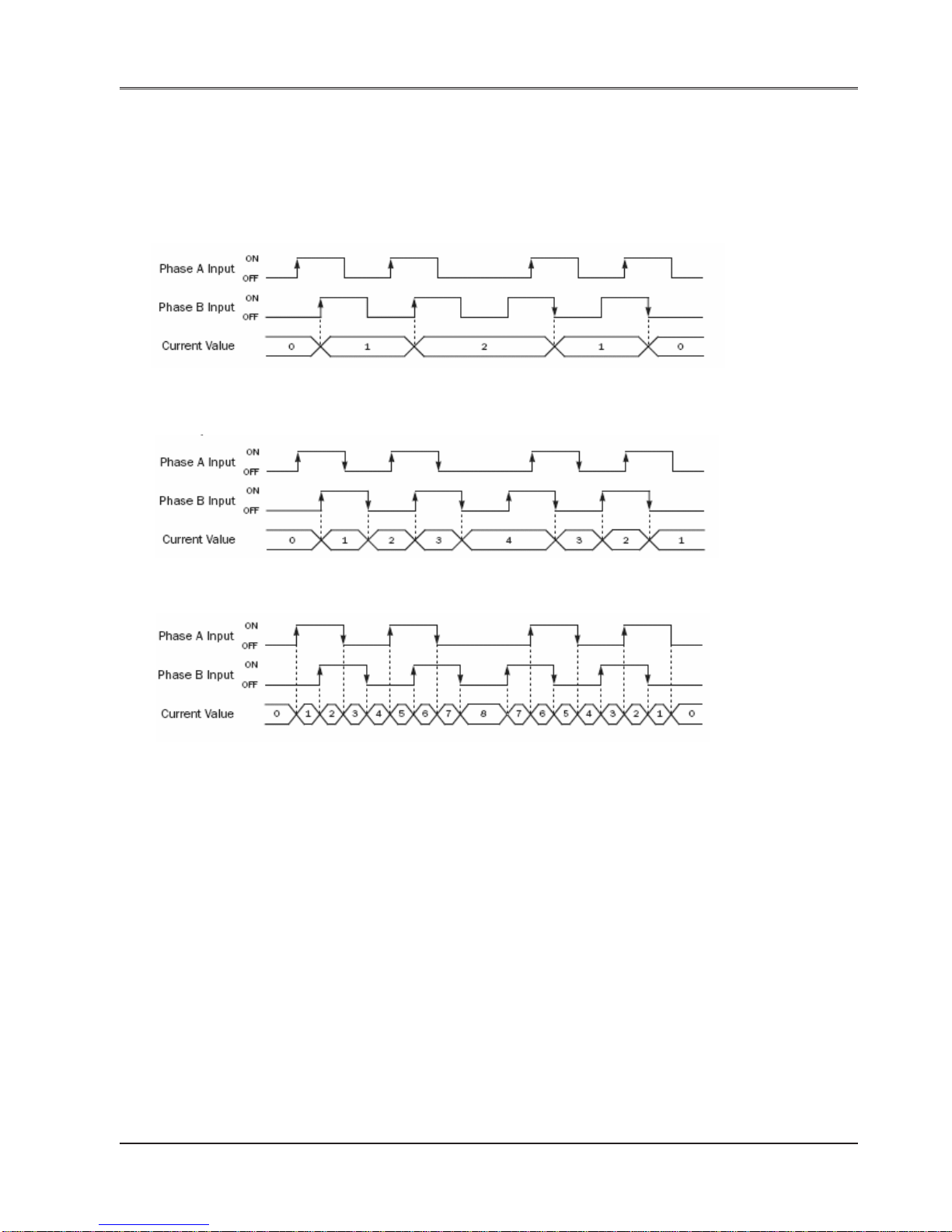
Special Input and Output
91
Doc No: UMAN\FL\01 10
Rev . No.: 1.02B
5.2.3 Quadrature bi-pulse counter
This function counts up or down the quadrature bi-pulse (2-phase pulses whose phases are shifted 90° each other).
Counts up when phase A precedes, and count s down when phase B precedes.
1-edge count:
The current value increments or decrements at the rising or falling edge of the phase B input after the phase A input
has turned on.
2-edge Count:
The current value increments or decrements at the rising or falling edge of the phase B input after the phase A input
has turned on or off.
4-edge Count:
The current value increments or decrements at the rising or falling edges of the phase A and B inputs.
Both rising and falling edges of each phase are counted.
Consequently , 4 times count value against the pulse frequency is obtained.
When the count value reaches the comparison value 1 (or 2), the I/O interrupt program#1 (or #2) is activated (if the
interrupt enable flag for each is ON). This counter operation is enabled while the soft-gate is ON. The count value is
reset to 0 when the soft-gate is changed from ON to OFF. The count value is also reset to 0 when the reset input
comes ON. When the soft-gate is OFF, the count value can be changed by writing the data into the comparison
value 1 (or 2) register and setting the count preset flag 1 (or 2) to ON. The comparison value 1 and 2 can be changed
even when the soft-gate is ON. The count value range is 0 to 4294967295 (32-bit data).

Special Input and Output
92
Doc No: UMAN\FL\01 10
Rev . No.: 1.02B
The function selection is done through configuration register1
Function Register/device Remarks
Phase A IP 1 (X000)
Phase B IP 2 (X001)
Reset input IP 3 (X002)
Comparison value 1 MW12 MW13 Data range: 0 to 4294967295
Comparison value 2 MW14 MW15
Count value MW16 MW17
Soft-gate M320 Operation is enabled when ON
Interrupt enable 1 M322 Interrupt 1 is enabled when ON
Count preset 1 M324 Used to preset the count value
Interrupt enable 2 M323 Interrupt 2 is enabled when ON
Count preset 2 M325 Used to preset the count value
Hardware condition:
Phase A and phase B (IP 1 and IP 2)
1X Mode
ON/OFF pulse width: 100 microsec. or more (max. 5 kHz)
2X Mode
ON/OFF pulse width: 100 microsec. or more (max. 5 kHz)
4X Mode
ON/OFF pulse width: 100 microsec. or more (max. 5 kHz)
Reset input (IP3)
ON/OFF duration: 2 ms or more
Interrupt assignment:
Comparison value 1 — I/O interrupt program #1
Comparison value 2 — I/O interrupt program #2

Special Input and Output
93
Doc No: UMAN\FL\01 10
Rev . No.: 1.02B
5.2.4 Interrupt Input Function
When the signal state of the interrupt input is changed from OFF to ON (or ON to OFF), the corresponding I/O
interrupt program is activated immediately . Up to 2 interrupt inputs can be used. The interrupt generation condition
can be selected either rising edge (OFF to ON) or falling edge (ON to OFF) for each input. The I/O interrupt program
#1 is corresponding to the interrupt input 1, and the I/O interrupt program #2 is corresponding to the interrupt input 2.
Hardware condition
Interrupt input (IP 1 and IP 2)
ON/OFF pulse width: 100 microsec. or more
Interrupt assignment
Interrupt input 1 — I/O interrupt program #1
Interrupt input 2 — I/O interrupt program #2
5.2.5 Pulse Output Function
There are two transistor outputs Y0 and Y1 and can be used for pulse output.
When CW/CCW mode is selected if frequency is positive, match output 1 will be selected so that pulses will be out
on Y0 and if frequency is negative match output 2 will be selected so that pulses will be out on Y1.
In PULSE/DIR mode the pulses will be out on Y0 i.e. Match output1. If the frequency is negative then direction pin
can be set to high through Match output 2.
Function Register/device Remarks
CW/ CCW PLS/DIR
CW Pulse PLS Y0
CCW Pulse DI R Y1
Pulse enable flag M336 Output is enabled when ON
Frequency setting register MW22 MW23 Data range: -5000 to –50, 50 to 5000
Frequency setting error flag M191 ON at error (Reset OFF automatically)

Special Input and Output
94
Doc No: UMAN\FL\01 10
Rev . No.: 1.02B
5.2.6 PWM Output Function
This function is used to output a variable duty cycle pulse train. The controllable duty cycle is 0 to 100 % (1 %
units). The PWM output is enabled when the pulse enable flag is ON. While the pulse enable flag is ON, the duty
cycle (ON duty) can be changed by changing the duty setting value (0 to 100). The frequency setting is available in
the range of 50 to 5000 Hz (1 Hz units) before turning ON the pulse enable flag. The frequency changing is not
allowed while the pulse enable is ON. Note that the minimum ON/OFF pulse duration is 100 microsec. Therefore, the
controllable ON duty range is limited depending on the frequency setting as follows. If the ON duty setting value is
not available (within 0 to 100), the pulse width error flag comes ON. (PWM output operation is continued but the duty
cycle is not guaranteed)
The function selection is done through configuration register2
Function Register/device Remarks
PWM pulse Y0
Pulse enable flag M336 Output is enabled when ON
Frequency setting register MW22 – MW23 Data range: 50 to 5000
ON duty setting register MW24 –MW25 Data range: 0 to 100
Pulse width error flag M189 ON at error (reset OFF automatically)
ON duty setting error flag M190 ON at error (reset OFF automatically)
Frequency setting error flag M191 ON at error (reset OFF automatically)
The Buffer is updated at each scan, so that the PWM frequency and duty cycle will be changed after each scan.

Operating System Overview
95
Doc No: UMAN\FL\01 10
Rev . No.: 1.02B
In this chapter. . . .
♦ Operating Modes
OPERATING SYSTEMS OVERVIEW

Operating System Overview
96
Doc No: UMAN\FL\01 10
Rev . No.: 1.02B
6.1 Operating System Overview
The FlexiLogics base models has three basic operation modes, the RUN mode, the HAL T mode and
the ERROR mode. It also has the HOLD and RUN-F modes mainly for system checking.
RUN: The RUN mode is a normal control-operation mode.
In this mode, the FlexiLogics base model reads input signals, executes the user program, and updates the output devices according to the user program. In the RUN mode,
FlexiLogics unit executes the user’s ladder program logic, which is the basic operation of
a PLC. In this mode task defined in the application are also executed.
EEPROM write are possible while the FlexiLogics base is in the RUN mode.
HAL T: The HALT mode is a STOP mode.
In this mode, user program execution is stopped and all outputs are brought to zero (0).
Program loading into the FlexiLogics base unit is possible in the HAL T mode.
ERROR: The ERROR mode is a shutdown mode as a result of self-diagnosis.
The FlexiLogics base model enters the ERROR mode if internal error is detected by selfdiagnosis. In this mode, program execution is stopped and all outputs are brought to
“Error State Output Condition” defined in the application. The cause of the shut down can
be confirmed by connecting the programming tool.
T o exit from the ERROR mode, execute the Error Reset command from the programming
tool, or cycle power off and then on again.
HOLD: The HOLD mode is provided mainly for checking the external I/O signals.
In this mode, user program execution is stopped, with input and output updating is
executed. It is therefore possible to suspend program execution while holding the output
state. Moreover, a desired output state can be established by setting any dat a by using
the programming tool.
RUN-F: The RUN-F mode is a forced RUN mode provided for program checking.
This mode is effective when using the expansion I/Os.
Different from the normal RUN mode, the RUN-F mode allows operation even if the
registered I/O modules are not actually mounted.
In this mode the physical outputs are not updated; only the registers are updated.
The operation modes are switched by the mode control switch provided on the FlexiLogics base model and the
mode control commands issued from the programming tool.

Programming Information
97
Doc No: UMAN\FL\01 10
Rev . No.: 1.02B
In this chapter. . . .
♦ Devices and registers
♦ Memory allocation of XW, YW and MW
♦ Index modifications
♦ Real-time clock/calendar
♦ User Program
♦ Pragramming Language
♦ Program execution Sequence
PROGRAMMING INFORMA TION

Programming Information
98
Doc No: UMAN\FL\01 10
Rev . No.: 1.02B
7.1 Devices Registers
Broadly two types of registers are present in PLC register database:
1. Internal PLC Registers: Implemented through buffers present in RAM of Base module.
Data Registers (D).
Auxillary Registers (BW/B).
System Registers (SW).
System coil (S).
Timer Registers (T).
Counter Registers (C).
Base module configuration Registers (MW/M) (Coils and registers are mapped)
I/O Registers of Base Module (XW/X, YW/Y) (Coils and registers are mapped)
Timer devices (T.)
Counter devices (C.)
2. Expansion and Serial I/O Registers: These are external to the unit and can be accessed by communicating with
external module over SPI or serial:
I/O Registers of expansion module and serial module (XW/X, YW/Y).
Configuration Registers (MW/M).
XW, YW , MW , X, Y, M register types of both the register types; viz: base, expansion and serial are encoded with the
following addressing scheme:
XWssrr
YWssrr ss: Slot Number
MWssrr rr: register number in slot ss
Xssccc
Yssccc ss: Slot Number
Mssccc ccc: coil number in slot ss
Note:
“0” (Zero) is the slot number of base module.

Programming Information
99
Doc No: UMAN\FL\01 10
Rev . No.: 1.02B
Y ou can allot “ss” (slot number) from “Project Information” docker window; “IO Allocation\Local” section as shown
below:
When you double click on the highlighted slot section; below shown window will appear:
Note: Here you have to allot slots seriallly only and if you tried to allott randomly; it will show an error as “Expansion
Modules for PLC are sequencial hence, previous slot can not be empty”
Double click on each
slot to assign model name
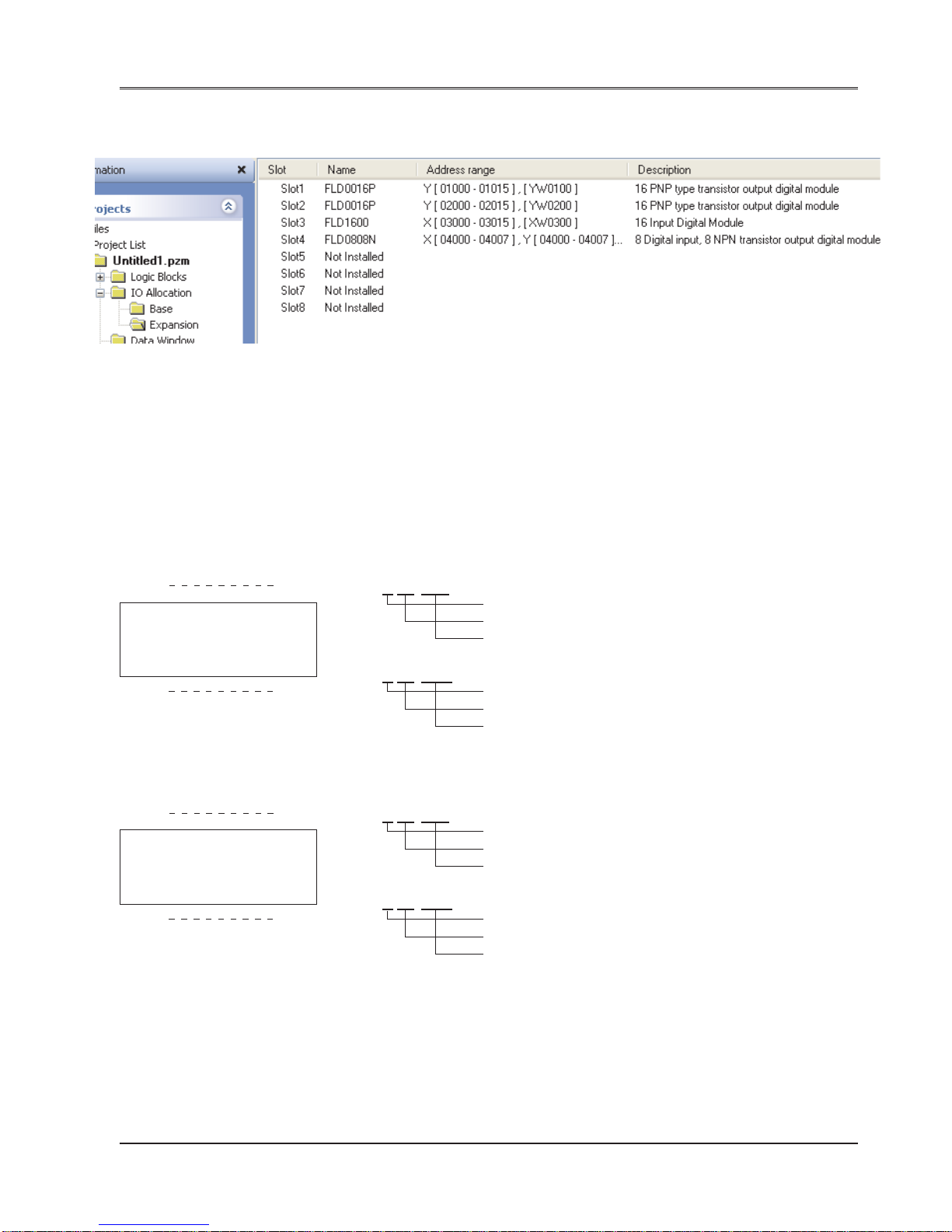
Programming Information
100
Doc No: UMAN\FL\01 10
Rev . No.: 1.02B
Thus, you can assign the expansion models as per your requirement as follows:
In the above shown screen, you can observe that the address range for the expansion models assign for Slot 1
through Slot 4, it has taken first two digit as 01, 02, 03 & 04 serially.
And last three digits will indiacate the register numbers.
The external input signals are allocated to the external input devices/registers (X/XW).
The external output signals are allocated to the external output devices/registers (Y/YW).
The register numbers of the external input and output registers are consecutive. Thus one register number can be
assigned for either input or output.
X01000 X01007 X 0 1 0 0 0
X: Input
Slot Number (Slot 1)
FLDD0808 Input: 8 Nos. (000 to 0007)
Y 0 1 0 0 0
Y01000 Y01007 Y: Output
Slot Number (Slot 1)
Output: 8 Nos. (000 to 007)
Similarly.....
X02000 X01003 X 0 2 0 0 0
X: Input
Slot Number (Slot 2)
FLD0404 Input: 4 Nos. (000 to 0003)
Y 0 2 0 0 0
Y02000 Y01003 Y: Output
Slot Number (Slot 2)
Output: 4 Nos. (000 to 003)
 Loading...