


ROVER
SERIES
20A | 30A | 40A
Version 1.5

Important Safety Instructions
Please save these instructions.
This manual contains important safety, installation, and operating instructions for the charge
controller. The following symbols are used throughout the manual to indicate potentially
dangerous conditions or important safety information.
WARNING
Indicates a potentially dangerous condition. Use extreme caution
when performing this task
CAUTION
NOTE
Indicates a critical procedure for safe and proper operation of the
controller
Indicates a procedure or function that is important to the safe and
proper operation of the controller
General Safety Information
Read all of the instructions and cautions in the manual before beginning the installation.
There are no serviceable parts for this controller. Do NOT disassemble or attempt to repair
the controller.
Do
NOT
allow water to enter the controller.
Make sure all connections going into and from the controller are tight.
Charge Controller Safety
NEVER connect the solar panel array to the controller without a battery. Battery must be
connected first.
Ensure input voltage does not exceed 100 VDC to prevent permanent damage. Use the
Open Circuit Voltage (Voc) to make sure the voltage does not exceed this value when
connecting panels together.
01

Battery Safety
Use only sealed lead-acid, flooded, gel or lithium batteries which
must be deep cycle.
Explosive battery gases may be present while charging. Be certain there is enough
ventilation to release the gases.
Be careful when working with large lead acid batteries. Wear eye protection and have
fresh water available in case there is contact with the battery acid.
Carefully read battery manuals before operation.
Do
NOT
let the positive (+) and negative (-) terminals of the battery touch each other.
Recycle battery when it is replaced.
Over-charging and excessive gas precipitation may damage the battery plates and
activate material shedding on them. Too high of an equalizing charge or too long of one
may cause damage. Please carefully review the specific requirements of the battery
used in the system.
Equalization is carried out only for non-sealed / vented/ flooded / wet cell lead acid
batteries.
Do
NOT
equalize VRLA type AGM / Gel / Lithium cell batteries UNLESS permitted by
battery manufacturer.
Default charging parameters in Li mode are programmed for 12.8V Lithium Iron
Phosphate (LFP) Battery only. Before using Rover to charge other types of lithium
battery, set the parameters according to the suggestions from battery manufacturer.
Please set the correct battery type the first time you use.
WARNING
Connect battery terminals to the charge controller BEFORE connecting
the solar panel(s) to the charge controller. NEVER connect solar panels to
charge controller until the battery is connected.
Do NOT connect any inverters or battery charger into the load terminal of
the charge controller.
Once equalization is active in the battery charging, it will not exit this stage
unless there is adequate charging current from the solar panel. There
should be NO load on the batteries when in equalization charging stage.
02

Table of Contents
General Information
Additional Components
Optional Components
Identification of Parts
Installation
Operation
LED Indicators
Rover Protections
System Status Troubleshooting
Error Codes
Maintenance
Fusing
Technical Specifications
Electrical Parameters
04
08
08
09
10
17
22
24
25
25
26
26
27
27
General
Battery Charging Parameters
ROVER: PV Power – Conversion Efficiency Curves
Dimensions
03
27
28
29
30

General Information
The Rover Series charge controllers are intelligent controllers suitable for various off-grid solar
applications. It protects the battery from being over-charged by the solar modules and
over-discharged by the loads. The controller features a smart tracking algorithm that maximizes the
energy from the solar PV module(s) and charge the battery. At the same time, the low voltage
disconnect function (LVD) will prevent the battery from over discharging.
The Rover's charging process has been optimized for long battery life and improved system
performance. The comprehensive self-diagnostics and electronic protection functions can prevent
damage from installation mistakes or system faults.
Key Features
Automatically detect
Innovative MPPT technology with high tracking efficiency up to 99% and peak
conversion efficiency of 98%
Deep cycle Sealed, Gel, Flooded and Lithium (12.8V LFP) battery option ready
Electronic protection: Overcharging, over-discharging, overload, and short circuit
Reverse protection: Any combination of solar module and battery, without causing
damage to any component
Customizable charging voltages
Charges over-discharged lithium batteries
RS232 port to communicate with BT-1 Bluetooth module
12V or 24V DC system voltages
MPPT Technology
The MPPT Charge Controller utilizes Maximum Power Point Tracking technology to extract
maximum power from the solar module(s). The tracking algorithm is fully automatic and
does not require user adjustment. MPPT technology will track the array’smaximum power point
voltage (Vmp) as it varies with weather conditions, ensuring that the maximum power is
harvested from the array throughout the course of the day.
Current Boost
In many cases, the MPPT charge controller will “boost” up the current in the solar system. The
current does not come out of thin air. Instead, the power generated in the solar panels is the
same power that is transmitted into the battery bank. Power is the product of Voltage (V) x
Amperage (A).
04

Therefore, assuming 100% efficiency:
Volts In * Amps In = Volts out * Amps out
Power In = Power Out
Although MPPT controllers are not 100% efficient, they are very close at about 92-95% efficient.
Therefore, when the user has a solar system whose Vmp is greater than the battery bank
voltage, then that potential difference is proportional to the current boost. The voltage generated
at the solar module needs to be stepped down to a rate that could charge the battery in a stable
fashion by which the amperage is boosted accordingly to the drop. It is entirely possible to have
a solar module generate 8 amps going into the charge controller and likewise have the charge
controller send 10 amps to the battery bank. This is the essence of the MPPT charge controllers
and their advantage over traditional charge controllers. In traditional charge controllers, that
stepped down voltage amount is wasted because the controller algorithm can only dissipate it
as heat. The following demonstrates a graphical point regarding the output of MPPT technology.
Current vs. Voltage (12V System) Output Power(12V System)
Typical Battery
Voltage Range
CURRENT
10 15 17
Maximum
Power Point
VOLTAGE
Maximum
Traditional
Controller
Operating
Range
CURRENT
10 15 17
Power Point
VOLTAGE
Limiting Effectiveness
Temperature is a huge enemy of solar modules. As the environmental temperature
increases, the operating voltage (Vmp
) is reduced and limits the power generation of the solar
module. Despite the effectiveness of MPPT technology, the charging algorithm will
not have much to work with and therefore there is an inevitable decrease in
In this scenario, it would be preferred to have modules with higher nominal
despite the drop in performance of the panel, the battery is still receiving
performance.
voltage, so that
a current boost
because of the proportional drop in module voltage.
05
possibly

Four Charging Stages
The Rover MPPT charge controller has a 4-stage battery charging algorithm for a rapid,
efficient, and safe battery charging. They include: Bulk Charge, Boost Charge, Float Charge,
and Equalization.
Battery
Voltage
Equalize
Boost
Float
Recharge
Battery
Current
A B C
Bulk Charge
Max Current
Constant charging
Duration Time:2h
(Range:10-180min)
Cumulative Time:3h
Float Charge
Boost
Bulk
Time
Time
Bulk Charge: This algorithm is used for day to day charging. It uses 100% of available solar
power to recharge the battery and is equivalent to constant current. In this stage the battery
voltage has not yet reached constant voltage (Equalize or Boost), the controller operates in
constant current mode, delivering its maximum current to the batteries (MPPT Charging) .
Constant Charging: When the battery reaches the constant voltage set point, the controller
will start to operate in constant charging mode, where it is no longer MPPT charging. The current
will drop gradually. This has two stages, equalize and boost and they are not carried out
constantly in a full charge process to avoid too much gas precipitation or overheating of the
battery.
Boost Charge: Boost stage maintains a charge for 2 hours by default. The user
can adjust the constant time and preset value of boost per their demand.
Float Charge: After the constant voltage stage, the controller will reduce the battery voltage
to a float voltage set point. Once the battery is fully charged, there will be no more chemical
reactions and all the charge current would turn into heat or gas. Because of this,
06

The charge controller will reduce the voltage charge to smaller quantity, while lightly charging
the battery. The purpose for this is to offset the power consumption while maintaining a full
battery storage capacity. In the event that a load drawn from the battery exceeds the charge
current, the controller will no longer be able to maintain the battery to a Float set point and the
controller will end the float charge stage and refer back to bulk charging.
Equalization: Is carried out every 28 days of the month. It is intentional overcharging of
the battery for a controlled period of time. Certain types of batteries benefit from periodic
equalizing charge, which can stir the electrolyte, balance battery voltage and complete
chemical reaction. Equalizing charge increases the battery voltage, higher than the standard
complement voltage, which gasifies the battery electrolyte.
WARNING
Once equalization is active in the battery charging, it will not exit this stage unless
there is adequate charging current from the solar panel. There should be NO load
on the batteries when in equalization charging stage.
WARNING
Over-charging and excessive gas precipitation may damage the battery plates
and activate material shedding on them. Too high of equalizing charge or for too
long may cause damage. Please carefully review the specific requirements of the
battery used in the system.
WARNING
Equalization may increase battery voltage to a level damaging to sensitive DC
loads. Ensure that all load allowable input voltages are greater than the equalizing
charging set point voltage.
Lithium Battery Activation
The Rover MPPT charge controller has a reactivation feature to awaken a sleeping lithium
battery. The protection circuit of lithium battery will typically turn the battery off and make it
unusable if over-discharged. This can happen when storing a lithium battery pack in a
discharged state for any length of time as self-discharge would gradually deplete the remaining
charge. Without the wake-up feature to reactivate and recharge batteries, these batteries would
become unserviceable and the packs would be discarded. The Rover will apply a small charge
current to activate the protection circuit and if a correct cell voltage can be reached, it starts a
normal charge.
CAUTION
When using the Rover to charge a 24V lithium battery bank, set the system
voltage to 24V instead of auto recognition. If auto recognition is accidently
selected the Rover will allow you to change it to 24V when the lithium battery
activation. In the activation interface press and hold the enter button to
trigger the system voltage selector. To change the system voltage, press the
Up or Down buttons then long press Enter to save the selected system voltage.
07

Additional Components
Additional components included in the package:
Remote Temperature Sensor:
This sensor measures the temperature at the battery and uses this
data for very accurate temperature compensation.The sensor is
supplied with a 9.8ft cable length that connects to the charge
controller.Simply connect the cable and adhere the sensor on top
or the side of the battery to record ambient temperature around the
battery.
NOTE
Do Not use this sensor when charging lithium battery.
Mounting Brackets
These brackets can be used to mount the Rover charge
controller on any flat surface. The screws to mount the
brackets to the charge controller are included, screws to
mount charge controller to surface are not included.
Mounting Oval:7.66 x 4.70mm (0.30 x 0.18in)
Optional Components
Optional components that require a separate purchase:
Renogy BT-1 Bluetooth Module:
The BT-1 Bluetooth module is a great addition to any Renogy charge
controllers with a RS232 port and is used to pair charge controllers with the
Renogy DC Home App. After pairing is done you can monitor your system
and change parameters directly from you cell phone or tablet. No more
wondering how your system is performing, now you can see performance
in real time without the need of checking on the controller’s LCD.
Renogy DM-1 4G Data Module:
The DM-1 4G Module is capable of connecting to select Renogy charge
controllers through an RS232, and is used to pair charge controllers with
Renogy 4G monitoring app. This app allows you to conveniently monitor
your system and charge syeters parameters remotely from anywhere 4G
LTE network service is available.
08

1
2
3
4
5
6
Identification of Parts
9 10 11
8
Key Parts
7
12
1. PV LED Indicator
2. Battery LED Indicator
3. Load LED Indicator
4. System Error LED Indicator
5. LCD Screen
6. Operating Keys
7. Mounting Holes
8. Remote Temperature Sensor Port (optional accessory)
9. PV Terminals
10. Battery Terminals
11. Load Terminals
12. RS-232 Port (optional accessory)
09

Installation
CHARGER
HIGH AMP
DRAWING DEVICE
Recommended tools to have before installation:
WARNING
WARNING
Screwdriver
Multi-Meter
Connect battery terminal wires to the charge controller FIRST then connect the
solar panel(s) to the charge controller. NEVER connect solar panel to charge
controller before the battery.
Do NOT connect any inverters or battery chargers into the LOAD TERMINAL of
the charge controller.
INVERTER
BATTERY
CAUTION
CAUTION
Do not over tighten the screw terminals. This could potentially break the
piece that holds the wire to the charge controller.
Refer to the technical specifications for max wire sizes on the controller and
for the maximum amperage going through wires.
You are now ready to begin connecting your battery to your charge controller.
10
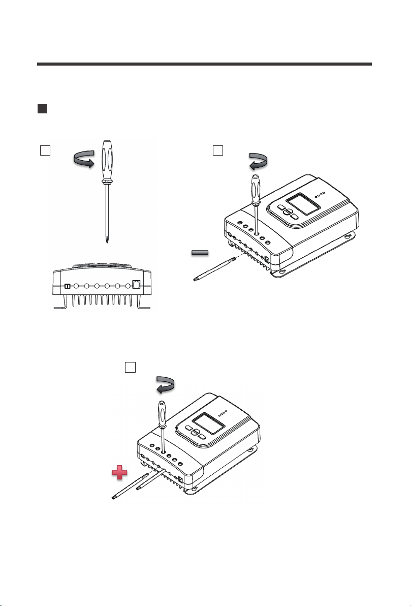
Battery
1 2
3
11

Load (optional)
1 2
Solar Panels
1 2
12
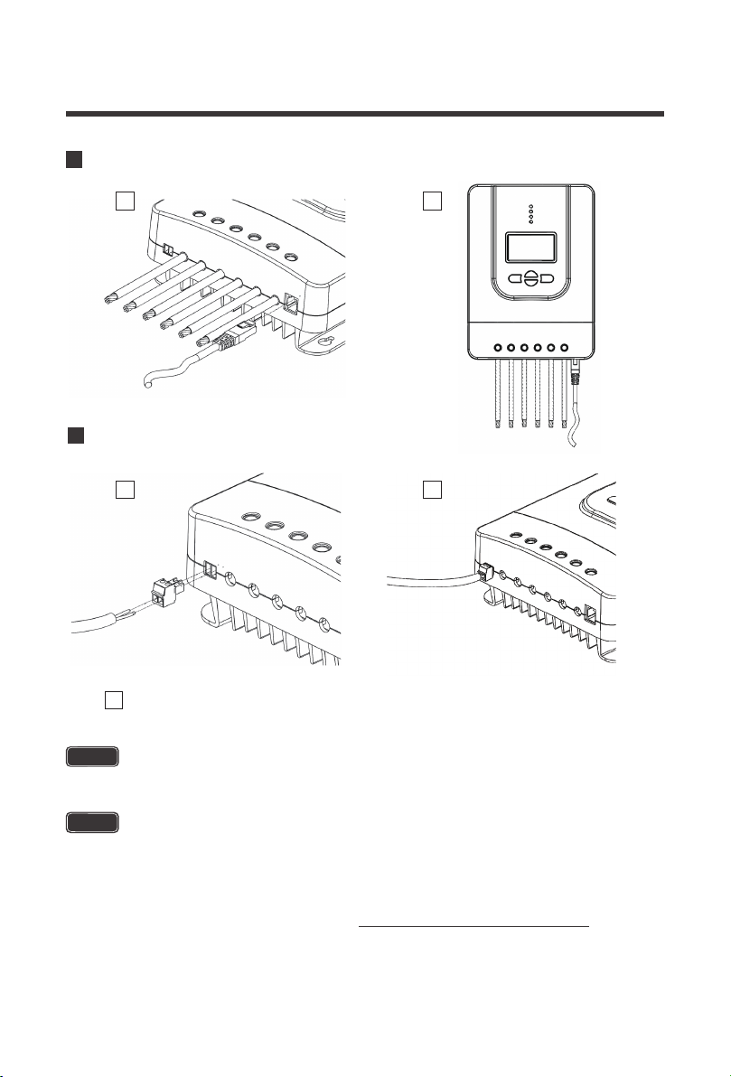
Bluetooth Module communication (optional)
1 2
Temperature Sensor (optional, not polarity sensitive)
1 2
3
Place the sensor close to the battery
NOTE
Do NOT place the Temperature Sensor lug inside the battery cell.
Mounting Recommendations
WARNING
Never install the controller in a sealed enclosure with flooded batteries. Gas can accumulate
and there is a risk of explosion.
1. Choose Mounting Location—place the controller on a vertical surface protected from
direct sunlight, high temperatures, and water. Make sure there is good ventilation.
13

2. Check for Clearance—verify that there is sufficient room to run wires, as well as clearance
above and below the controller for ventilation. The clearance should be at least 6 inches (150mm).
3. Mark Holes
4. Drill Holes
5. Secure the charge controller.
6 inches
(150mm)
warm air
6 inches
(150mm)
Mounting Methods
The controller can be mounted using the existing mounting holes or using the included mounting
brackets.
cool air
14

Using Mounting Hole
Step 1.
Measure the distance between each
mounting hole on the Rover. Using that
distance drill 4 screws onto desired surface.
Step 2.
Align the Rovers mounting holes with the
screws
Step 3.
Verify all screw heads are inside the
mounting holes. Release controller and
check if mounting feels secure.
15

Using Mounting Brackets
Step 1.
Install the brackets using the provided
components
Step 2.
Align the mounting brackets to desired
surface and use the appropriate screws to drill
into surface (screws not included)
Step 3.
Verify mounting is secure
16

Operation
Rover is very simple to use. Simply connect the batteries, and the controller will automatically
determine the battery voltage. The controller comes equipped with an LCD screen and 4
buttons to maneuver though the menus.
NOTE:Please set the correct battery type the first time you use.
Startup Interface
Main Display
NOTE
The Battery Capacity (SOC%) is estimated based on the charging voltage.
Error Code
Load mode
Main Screen
Solar Panel Voltage
Battery Voltage
Load Current
Controller
Temperature
Charging Current
Accumulated AH
Battery Capacity
Discharged AH
17

/
/ -
Page Up/ Increase parameter value
Page Down/ Decrease parameter value
Return to the previous menu
ENTER/
Enter sub menu/ save parameter value/
turn load on or off in manual mode
18

Programming Battery Type
To enter the battery programming settings hover over the Battery Voltage screen and press
down the Enter button .When the battery type starts to flash press the Select button to cycle
through the battery types and press Enter to finalize selection .When selecting the Lithium
setting the user can change battery voltage from 12V to 24V and select the charging voltage.
Li
12V
SLD
GEL
FLD
USE
24V
12V / 24V
19

Programming Parameters
Battery type System voltage Equalizing voltage
Over-discharge voltage
Over-discharge
return voltage
Float voltage
Boost voltage
To enter the programming interface simply press and hold the right arrow button. After entering
this feature press the Enter/Right button to switch between parameters. To change the
parameters, press the Up or Down button. To save the parameter press and hold the
Enter/Right button.
The charging parameter setting (Equalizing voltage, Boost voltage, Floating charging voltage,
over-discharge return voltage, Over-discharge voltage) are only available under the battery
“USER” mode. Press and hold the right arrow to enter the programming settings and continue
pressing the right arrow button until you see the desired voltage screen.
NOTE
Battery charging parameters can also be programmed using the Renogy DC Home APP.
Read the corresponding user manuals for more information.
20

Programming Load Terminal
1 2 3 4
1. This screen is displaying the current Load Mode.
2. To enter screen 2 press and hold t
he Enter button. This screen will allow you to change
the load mode.
3. To change the load mode press the up or down button.
Once you have selected the desired load mode press the Enter button to save the setting.
4.
5. To exit the programming setting press the left button.
Load Mode Options
Setting Mode Description
The load will turn on at night when the solar
0 Automatic(On/Off)
panel is no longer producing any power
after a short time delay. The load will turn
off when the panel starts producing power.
When the panel is no longer producing
1-14
Time control
power the load will be ON for 1-14 hours
or until the panel starts producing power.
In this mode, the user can turn the Load
15 Manual
On/Off by pressing the Enter button at any
time.
Used to troubleshoot load terminal (No
16 Test
Time Delay). When voltage is detected
load will be off and when no voltage is
detected load will be on.
17
21
24Hr
The load will be on for 24 hours a day.

LCD Indicators
nighttime daytime solar panel charging
charging stage system voltage setting serial port bluetooth abnormality battery type unit
LED Indicators
battery discharging load parameter value
①---PV array indicator
①
②---BAT indicator
②
③
③---LOAD indicator
④
④---ERROR indicator
Indicating the controller's current
charging mode.
Indicating the battery's current state.
Indicating the loads' On/ Off state.
Indicating whether the controller is
functioning normally.
22

PV Indicator (1)
Status
Solid
White
White Slow Flashing
White Single Flashing
White Fast Flashing
White Double Flashing
Off
BATT Indicator (2)
White Solid
White Slow Flashing
White Fast Flashing
LOAD Indicator (3)
White Solid
White Fast Flashing
The PV system is charging the battery bank
The Controller is undergoing boost stage
The Controller is undergoing float stage
The Controller is undergoing equalization stage
The oversized PV system is charging the battery
bank at the rated current.
The PV system is not charging the battery bank.
PV not detected.
Status
Battery is normal
Battery over-discharged
Battery over-voltage
Status
Load is on
Load is over-loaded or short-circuited
Off
ERROR Indicator (4)
White Solid
System Error. Please check LCD for Error code
Off
23
Load is off
Status
System is operating normally

Rover Protections
Protection Behavior
PV Array Short Circuit
PV Overvoltage
PV Overcurrent
Load Overload
Load Short Circuit
PV Reverse Polarity
Battery Reverse Polarity
When PV shot circuit occurs, the controller will stop charging.
Clear it to resume normal operation.
if the PV voltage is larger than maximum input open voltage
100VDC. PV will remain disconnected until the voltage drops
below 100VDC.
The controller will limit the battery charging current to the
maximum battery current rating. Therefore, an over-sized
solar array will not operate at peak power.
If the current exceeds the maximum load current rating 1.05
times, the controller will disconnect the load. Overloading
must be cleared up by reducing the load and restarting the
controller.
Fully protected against the load wiring short-circuit. Once the
load short (more than quadruple rate current), the load short
protection will start automatically. After 5 automatic load
reconnect attempts, the faults must be cleared by restarting
the controller.
The controller will not operate if the PV wires are switched.
Wire them correctly to resume normal controller operation.
The controller will not operate if the battery wires are
switched. Wire them correctly to resume normal controller
operation.
Over-Temperature
If the temperature of the controller heat sink exceeds 65℃,
the controller will automatically start reducing the charging
current. The controller will shut down when the temperature
exceeds 85℃.
24

System Status Troubleshooting
PV indicator Troubleshoot
Ensure that the PV wires are correctly and tightly secured inside
Off during daylight
BATT Indicator Troubleshoot
White Slow Flashing
the charge controller PV terminals. Use a multi-meter to make
sure the poles are correctly connected to the charge controller.
Disconnect loads, if any, and let the PV modules charge the battery
bank. Use a multi-meter to frequently check on any change in battery
voltage to see if condition improves. This should ensure a fast charge.
Otherwise, monitor the system and check to see if system improves.
White Fast Flashing
Load Indicator Troubleshoot
White Fast Flashing
Error Indicator Troubleshoot
WhiteSolid System Error. Please check LCD for Error code
Using a multimeter check the battery voltage and verify it is not
exceeding 32 volts.
The Load circuit on the controller is being shorted or
overloaded. Please ensure the device is properly connected to
the controller and make sure it does not exceed 20A (DC).
Error Codes
Error Number Description
E0
E1
E2
E3
E4 Load short circuit
E5 Load overloaded
E6
E8
E10
No error detected
Battery over-discharged
Battery over-voltage
Battery under-voltage
Controller over-temperature
PV input over-current
PV over-voltage
25

Maintenance
WARNING
For best controller performance, it is recommended that these tasks be performed from time to time.
1. Check that controller is mounted in a clean, dry, and ventilated area.
2. Check wiring going into the charge controller and make sure there is no wire damage or wear.
3. Tighten all terminals and inspect any loose, broken, or burnt up connections.
4. Make sure LED readings are consistent. Take necessary corrective action.
5. Check to make sure none of the terminals have any corrosion, insulation damage, high
temperature, or any burnt/discoloration marks.
Risk of Electric Shock! Make sure that all power is turned off before touching the
terminals on the charge controller.
Fusing
Fusing is recommended in PV systems to provide a safety measure for connections going from
panel to controller and controller to battery. Remember to always use the recommended wire
gauge size based on the PV system and the controller.
NEC Maximum Current for different Copper Wire Sizes
AWG 16 14 12 10 8 6 4 2 0
Max.
Current
Note: The NEC code requires the overcurrent protection shall not exceed 15A for 14AWG, 20A
for 12 AWG, and 30A for 10AWG copper wire.
Controller to Battery Fuse = Current Rating of Charge Controller
Ex. 20A MPPT CC = 20A fuse from Controller to Battery
Fuse from Controller to Battery
55A40A30A25A18A
75A 95A 130A 170A
Fuse from Solar Panel(s) to Controller
Ex. 200W; 2 X 100 W panels
NOTE
Different safety factors could be used. The purpose is to oversize.
Series:
Total Amperage= Isc1 = Isc2 * SF
= 5.75A * 1.56 = 8.97 =(5.75A + 5.75A)* 1.56 = 17.94
**Utilize 1.56 Sizing Factor (SF)
Parallel
Total Amperage= (Isc1 + Isc2) * SF
Fuse = 18A fuse Fuse = 9A fuse
26

Electrical Parameters
Technical Specifications
Model
Nominal system voltage
Rated Battery Current
Rated Load Current
Max. Battery Voltage
Max Solar Input Voltage
Max. Solar Input Power
Self-Consumption
Charge circuit voltage drop
Discharge circuit voltage drop ≤ 0.15V
Temp. Compensation
32V
≤ 0.26V
RVR-20 RVR-30 RVR-40
12V/24V Auto Recognition
20A
20A
12V @ 260W
24V @ 520W
-3mV/°C/2V (default)
30A
20A
100 VDC
12V @ 400W
24V @ 800W
≤100mA @ 12V
≤58mA @ 24V
General
Dimensions
Mounting Oval
Max Terminal Size
Net Weight
Model
RVR-20 RVR-30/40
210*151*68.2mm
8.27*5.95*2.69in
7.66 x 4.70mm
0.30 x 0.18in
2
10mm
8 AWG
1.4kg
3.08 lb.
24V @ 1040W
238*172*77.3mm
9.38*6.78*3.05in
10mm
8 AWG
2.0kg
4.41 lb.
40A
20A
12V @ 520W
2
Working Temperature
Storage Temperature
Rated Load Current
Humidity Range
Enclosure IP32
Altitude < 3000m
Communication
Certification
27
FCC Part 15 Class B; CE; RoHS; RCM
-35°C to +45°C
-35°C to +75°C
10% to 90% NC
≤ 95% (NC)
RS232

This equipment has been tested and found to comply with the limits for a class B digital
device, pursuant to part 15 of the FCC Rules. These limits are designed to provide reasonable
protection against harmful interference in a residential installation. This equipment generates,
uses and can radiate radio frequency energy and if not installed and used in accordance with
the instructions, may cause harmful interference to radio communications. However, there is
no guarantee that interference will not occur in a particular installation. If this equipment does
cause harmful interference to radio or television reception, which can be determined by
turning the equipment off and on, the user is encouraged to try to correct the interference by
one or more of the following measures:
•Reorient or relocate the receiving antenna.
•Increase the separation between the equipment and receiver.
•Connect the equipment into an outlet on a circuit different from that to which the receiver is connected.
•Consult the dealer or an experienced radio/TV technician for help.
This device complies with Part 15 of the FCC Rules. Operation is subject to the following two
conditions: (1) this device may not cause harmful interference, and (2) this device must accept
any interference received, including interference that may cause undesired operation.
Battery Charging Parameters
Battery GEL SEALED FLOODED LI (LFP) USER
Over-voltage
Warning
Equalization
Voltage
Boost Voltage
Float Voltage 13.8 V 13.8 V 13.8 V -----
Boost Return
Voltage
Under Voltage
Warning
Under Voltage
Recover
Low Voltage
Disconnect
Low Voltage
Reconnect
Equalization
Duration
Boost Duration
16 V 16 V 16 V 16 V
-----
14.6 V
-----
14.4 V14.6 V 14.4 V 14.2 V
13.2 V 13.2 V 13.2 V 13.2 V
12V 12V 12V 12V
12.2 V 12.2 V 12.2 V 12.2 V
11.0V 11.0V 11.0V 11.0V
12.6 V 12.6 V 12.6 V 12.6 V
-----
2 hours 2 hours 2 hours
2 hours 2 hours
-----
-----
9-17 V
9-17 V14.8V
9-17 V
9-17 V
9-17 V
9-17 V
9-17 V
9-17 V
9-17 V
0-10 Hrs.
1-10 Hrs.
*Battery charging parameters in USER mode can be programmed using the Renogy DC
Home App.
**Default charging parameters in LI mode are programmed for 12.8V LFP battery. Before
using Rover to charge other types of lithium battery, set the parameters according to the
suggestions from battery manufacturer.
***Parameters are multiplied by 2 for 24V systems.
28

Rover– Conversion Efficiency Curves
2
1.12 Volt System Conversion Efficiency
MPPT 12V conversion efficiency (12V battery)
96%
95%
Conversion efficiency Conversion efficiency
94%
93%
92%
91%
90%
89%
88%
87%
525 500 475 450 425 400
550
Output power(W)
2. 24 Volt System Conversion Efficiency
MPPT 24V conversion efficiency (24V battery)
87%
Temp 25℃Illumination Intensity: 1000W/ m
20 Vmp
40 Vmp
60 Vmp
75 Vmp
375 350 300 250 200 150 100 50
96%
94%
92%
90%
40 Vmp
50 Vmp
60 Vmp
75 Vmp
88%
86%
1100 1000 900 800 600 500 300 100
Output power(W)
29

Dimensions
RVR-20
210
RVR-30/40
238
151
13.87
150.40
R4.0
68.20 131
154.00
R2.25
Product dimensions:210*151*68.2mm
117.32
143.63
172 77.30 147
Maximum Wire Gauge 8 AWG
R2.60
R4.50
24.30
R2.60
R2.25
R4.0
18
123.46
167.60
Product dimensions:238*172*77.3mm
Maximum Wire Gauge 8 AWG
NOTE
Dimensions in millimeters (mm)
R5.00
30

RENOGY.COM
Renogy reserves the right to change
the contents of this manual without notice.
US
CN
JP
CA
AU
UK
DE
2775 E Philadelphia St, Ontario, CA 91761, USA
909-287-7111
www.renogy.com
support@renogy.com
苏州高新区科技城培源路1号5号楼-4
400-6636-695
https://www.renogy.cn
support@renogy.cn
https://www.renogy.jp
supportjp@renogy.com
https://ca.renogy.com
supportca@renogy.com
https://au.renogy.com
supportau@renogy.com
https://uk.renogy.com
supportuk@renogy.com
https://de.renogy.com
supportde@renogy.com

ROVER
SERIES
20A | 30A | 40A
Version 1.5

Wichtige Sicherheitshinweise
Bitte beachten Sie die folgenden Hinweise.
Die folgenden Symbole veranschaulichen die Verwendung des gesamten Handbuchs, um
anzuzeigen, dass eine potenziell gefährliche Situation in einer Operation oder eine wichtige
sichere Prozedur vorhanden sein kann, die berücksichtigt werden muss.
WARNUNG
Weist auf einen möglicherweise gefährlichen Betrieb
hin, der zu Verletzungen führen kann.
ACHTUNG
HINWEIS
Zeigt ein kritisches Verfahren für den sicheren und ordnungsgemäßen
Betrieb des Solarladereglers.
Zeigt die wichtigen Spezifikationen und Verfahren für die Verwendung
dieses Solarladereglers an.
Allgemeine Sicherheitshinweise
Lesen Sie alle Anweisungen und Vorsichtsmaßnahmen im Handbuch vor der Installation.
Innerhalb des Solarladereglers ist keine Wartung oder Reparatur erforderlich. Zerlegen
und warten Sie den Solarladeregler nicht selbst.
Verhindern, dass Wasser in das Innere des Solarladereglers eindringt.
Stellen Sie sicher,dass alle Leitungsverbindungen dicht sind.
Sicherheitshinweise zum Laderegler
Stellen Sie sicher, dass die Batterie vor der Installation korrekt angeschlossen ist.
Stellen Sie sicher, dass die Eingangsspannung weniger als 100 V beträgt, um dauerhafte
Schäden zu vermeiden. Schalten Sie den Leerlauf Spannung (Voc)ein, um sicherzustellen,
dass er unter dieser Spannung liegt,wenn er an Solarmodule angeschlossen wird.
31

Sicherheitshinweise der Batterie
Verwenden Sie nur Batterie mit hohen Zyklus: versiegelte Blei-Säure-, Flut-, Gel- oder
Lithium-Batterien.
Zum Zeitpunkt des Ladevorgangs kann das Batterie-Blasgas vorhanden sein, wodurch
ausreichend Raum zum Freisetzen des Gases sichergestellt wird.
Seien Sie vorsichtig, wenn Sie eine große Kapazität von Blei-Säure-Batterien
benutzen. Tragen Sie eine Schutzbrille. Wenn Batteriesäure in die Augen gelangt,
spülen Sie bitte mit sauberem Wasser ab.
Lesen Sie die Anweisungen des Akkus sorgfältig durch, bevor Sie fortfahren.
Lassen Sie nicht die positiven (+) und negativen (-) Anschlüsse der Batterie
miteinander berühren.Recyceln Sie die Batterie, wenn sie ersetzt wird.
Bitte recyceln Sie die Batterie, wenn er ersetzt wird
Übermäßige Ladephase Überschüssige Gasfällung kann die Batterieplatte
beschädigen und dazu führen, dass das aktive Material abfällt. Zur hohen oder langen
Ausgleichsladung führen zu einer Beschädigung der Batterie. Bitte überprüfen Sie
sorgfältig die spezifischen Anforderungen für die Batterie im System.
Der Ausgleich wird nur für nicht verschlossene / belüftete / geflutete /
Nasszellen-Blei-Säure-Batterien durchgeführt.
NICHT ausgleichen VRLA-Batterien vom Typ AGM / Gel / Lithiumzellen, WENN NICHT
vom Batteriehersteller zugelassen.
Die voreingestellten Ladeparameter im Li-Modus sind nur für 12,8
V-Lithium-Eisenphosphat-Akkus (LFP) programmiert. Bevor Sie Rover zum Laden
anderer Lithiumbatterietypen verwenden, stellen Sie die Parameter gemäß den
Empfehlungen des Batterieherstellers ein
Bitte stellen Sie beim ersten Verwenden den richtigen Batterietyp ein.
WARNUNG
Verbinden Sie die Batterieklemmen mit dem Laderegler, BEVOR Sie
Solarmodul an den Laderegler anschließen. NIEMALS Solarmodule an
den Laderegler anschließen ohne die Verbindung von der Batterie.
Schließen Sie nicht Wechselrichter oder Ladegeräte an den
Lastanschluss des Ladereglers an
Als der Ausgleich beim Aufladen der Batterie aktiv ist, wird er diese Stufe
nicht verlassen, es sei denn, ein ausreichender Ladestrom vom
Solarpanel ist vorhanden. Die Batterien dürfen während des
Ausgleichsladezustands KEINE Last haben
32

Gliederung
Informationen
Zusatzkomponenten
Optionale Zubehöre
Identifizierung der Komponenten
Installation
Betrieb
LED-Anzeige
Rover-Schutz
Systemstatusüberholung
Fehlercodes
Wartung und Reparatur
Sicherung
Technische Parameter
Elektrische Parameter
34
38
38
39
40
47
52
54
55
55
56
56
57
57
Allgemein
Batterieladeparameter
ROVER: Leistungskurve der PV-Leistungsumwandlung
Maße
33
57
58
59
60

Informationen
Die Laderegler der Rover -Serie eignen sich für verschiedene netzunabhängige
Solaranwendungen. Sie schützt die Batterie vor Überladung des Solarmoduls und die Überlastung
durch die Lasten. Die Steuerung verwendet einen intelligenten Verfolgungsalgorithmus, um die
vom PV-Modul gewonnene Energie zu maximieren und die Batterie aufzuladen. Zur gleichen Zeit,
Niederspannung trennt die Funktion (LVD), um übermäßige Batterieentladung zu verhindern.
Das Ladeprogramm von Rover ist optimiert, um die Batterielaufzeit zu verlängern und die
Systemleistung zu verbessern.Umfassende Selbstdiagnose und elektronische
Schutzfunktionen können Schäden an einem Installationsfehler oder Systemausfall
verhindern.
Hauptmerkmale
Automatische Erkennung von 12V oder 24V DC Systemspannung
Innovative MPPT-Technologie mit einer hohen Tracking-Effizienz von bis zu 99% und
einem maximalen Effizienz der Wirkungsgrad von bis zu 98%
Tieftopfdichtung, Kolloid, reichflüssige und Lithium-Eisen-Phosphat-Batterie(12,8V) bereit
Elektronischer Schutz: Überladung, Überentladung, Überlastung und Kurzschluss
Rückwärtsschutz: JEs gibt Schutz in der Verbindung zwischen Solarmodulen und
Batterien
Die Ladespannung kann eingestellt werden
Es kann auf überentladene Lithium-Eisenphosphat-Batterie geladen werden
RS232-Anschluss für die Verbindung von BT-1 Bluetooth Modul
MPPT-Technik
Der MPPT-Solarladeregler nutzt die Technologie der maximalen Leistungspunktverfolgung,
um die maximale Leistung aus dem Solarmodul zu extrahieren, und die Batterie aufzuladen.
Der Tracking-Algorithmus ist vollständig automatisch und erfordert keine
Benutzeranpassung. MPPT-Technologie verfolgt die Arrays maximale Leistung Punkt
Spannung (Vmp), wie es mit den Wetterbedingungen variiert, so dass die im Laufe des
Tages wird die maximale Leistung aus dem Array gewonnen.
Stromerhöhung
In den meisten Fällen wird der Ladestrom der Solaranlage durch die Technologie der
maximalen Leistungspunktverfolgung "verbessert". Der Strom ist nicht aus der Luft
gekommen,im Gegenteil, die Leistung von Solarmodule und Batterie Sendeleistung sind
gleich erzeugt. Die Leistung ist multiplizierte Wert von Spannung (V) und Strom (A).
34

Nehmen wir daher unter 100% Effizienzbedingungen an:
Eingangsspannung * Eingangsstrom = Ausgangsspannung * Ausgangsstrom
Eingangsleistung = Ausgangsleistung
Obwohl der Wirkungsgrad des MPPT-Solarladereglers nicht 100% beträgt, liegt seine Effizienz
dennoch bei 92-95%.Wenn die Solarkomponente eine Spitzenleistungspunktspannung
(Vmp) hat, die größer als die Batteriespannung ist kann es den Batterieladestrom proportional
größer als der Ausgangsstrom des Solarmoduls führen. Die vom Solarmodul erzeugte
Spannung muss auf den vorgesehenen Wert reduziert werden, um das Aufladen der Batterie
zu stabilisieren. Dies kann der Fall sein, wenn das Solarpanel einen Strom von 8A an die
Steuerung erzeugt aber die Steuerung der Batterie einen Ladestrom von 10A gibt. Dies ist das
Grundprinzip des MPPT-Solarladereglers und seine Vorteile gegenüber herkömmlichen
Solarladereglern. Der Einsatz des traditionellen Solarladereglers für die Abnehmende
Strommenge kann nur in Form von Wärme erfolgen, so dass die Umwandlungsrate relativ
gering ist. Die folgende Abbildung zeigt die Eigenschaften der MPPT-Technologie.
Strom und Spannung (12V-System) Ausgangsleistung (12V-System)
Typischer
Batteriespannungsbereich
Maximale
konventioneller
Leistungspunkt
SolarladereglerBetriebsbereich
10 15 17
Spannung
Strom
10 15 17
Maximaler
Leistungspunkt
Spannung
Strom
Effizienzlimit
Temperatur ist der Feind der Solarmodule": Die Temperatur wird sich die Effizienz der
Solarmodule auswirken. Trotz der hohen Effizienz der MPPT-Technologie kann der
Ladealgorithmus immer noch viele gute Bedingungen fehlt, so dass die
Steuerungsleistung unvermeidbar reduziert wird. In diesem Fall ist es vorzuziehen, eine
höhere Nennspannungskomponente zu haben, so dass die Batterie trotz der
Leistungsverschlechterung der Komponente aufgrund des proportionalen Abfalls der
Komponentenspannung immer noch eine Stromverstärkung empfängt.
35

Vierstufige Ladestufe
Der Solarregler Rover MPPT verfügt über vier schnelle, effiziente und sichere
Batterieladeverfahren. Sie umfassen: schnelles Aufladen, Anhebendes
Aufladen,Schwebeladung und ausgeglichenes Aufladen in vier Stufen.
Batteriespannung
Ausgleichserhöhung
Ladungsrückkehrspannung
Ladestrom
Schnelle Ladephase: für die tägliche Aufladung. Der Regler liefert 100% der zur Verfügung
A B C
Schnelle Ladung
Maximaler
Strom
behaltende Ladung
behaltende zeit:2 St.
(Anwendungsbereich:10-180 Min.
Akkumulierte Zeit: 3 St.
Erhaltungsladung
Boost
Bulk
Time
Time
stehenden Solarenergie zur Batterieladung, konstante strom-äquivalent.In dieser Phase hat
sich die Batteriespannung eine konstante Spannung (Ausgleichs- oder boost) nicht erreicht
wird, arbeitet Steuerung im konstanten Strom-Modus, der maximale Strom für die Batterie liefert
(MPPT Aufladung).
Behaltende Ladephase: Wenn die Batterie auf den Sollwert der konstanten Spannung
aufgeladen wird, wird die Steuerung startet bei einem konstanten Aufladung und ist nicht mehr
Ladung MPPT.Zu diesem Zeitpunkt wird der Strom allmählich abnehmen, aufgeteilt in zwei
Stufen des Ausgleichens und des Hebens, um das Überhitzen der Batterie zu verhindern und
die Erzeugung von Gas zu vermeiden, wird sie einen vollständigen Ladevorgang nicht
fortsetzen.
Hebephase : U m die Ladephase der allgemeinen Standarddauer von 2 Stunden zu
verbessern, kann der Benutzer auch die behaltende Zeit anpassen und den
Spannungspunkt des Standardwerts aufwerten. Wenn die Dauer den eingestellten
Wert erreicht, wird das System auf die Erhaltungsladung übertragen.
Erhaltungsladungsphase: Wenn die Batterie-Konstante Strom-Ladephase abgeschlossen
ist, schaltet der Solarladeregler in die Erhaltungsladephase.Wenn die Batterie vollständig
aufgeladen ist, gibt es keine elektrochemische Reaktion mehr. Zu diesem Zeitpunkt wird der
gesamte Ladestrom in Wärme und Niederschlaggas umgewandelt.Zu diesem Zeitpunkt wird die
Erhaltungsladungsphase ausgeführt, und die Batterie wird sehr schwach mit einer kleineren
Spannung und einem kleineren Strom aufgeladen.
36

Der Zweck der Erhaltungsladung besteht darin,die Batterie aufgrund der Selbstentladung zu kompensieren
und das System durch den Stromverbrauch eine geringere Last zu erzeugen, während die
Batteriespeicherkraft voll gehalten wird. Während der Erhaltungsladungsphase kann die Last weiterhin
Energie von der Batterie aufnehmen.Wenn die Systemlast den Solarladestrom überschreitet, kann die
Steuerung die Batteriespannung nicht mehr im eingestellten Erhaltungsladewert halten.Wenn die
Batteriespannung niedriger als die Ladungsrückgewinnungseinstellung ist, verlässt die Steuerung die
Erhaltungsladungsphase und kehrt zur Schnellladephase zurück.
Gleichgewichtsphasen: 28 Tage automatisch einmal ausgeführt, Es kann man aber auch manuell erfolgen.Einige
Batterietypen profitieren von regulärem Ausgleichsladen,können den Elektrolyten rühren, die Batteriespannung
ausgleichen und die chemische Reaktion abschließen.Die ausgeglichene Ladung erhöht die Batteriespannung damit
siehöher als die Standardkomplementärspannung und führt zur Elektrolytvergasung der Batterie.
WARNUNG
Wenn die Batterieladung ausgeglichen ist, wird das Gerät nicht verlassen, es sei denn, das Solarmodul
hat genügend Ladestrom. Während der ausgeglichenen Ladephase darf die Batterie nicht belastet
werden.
Überladung und übermäßige Gasniederschläge können die Batterieplatten beschädigen und
Materialablagerungen bewirken. Eine zu hohe oder zu lange Ausgleichsladung kann zu Schäden führen.
Bitte überprüfen Sie sorgfältig die spezifischen Anforderungen der im System verwendeten Batterie.
Eine ausgeglichene Ladung kann die Batteriespannung auf einen Wert erhöhen,der die empfindliche
Gleichstromlast beschädigen könnte. Stellen Sie sicher,dass alle im System zulassende Eingangsspannung der
Lasten größer als die Batterieausgleichsladungseinstellung ist.
Aktivierung der Lithium-Eisenphosphat-Batterie
Rover MPPT-Solarregler mit Lithium-Eisenphosphat-Batterie-Aktivierungsfunktion, können Sie den
Schlafzustand der Lithium-Eisenphosphat-Batterie aktivieren.Wenn es übermäßige entlädt,
Lithium-Eisen-Phosphat-Batterie-Schutzschaltung wird in der Regel die Batterie Entladeschaltung
abgeschnitten, so dass es nicht verwendet werden kann.Der Hauptgrund für diese Situation ist, dass der
Benutzer die Lithium-Eisenphosphat-Batterie zu dem Überentladungsschutzpunkt oder in der Nähe des
Freigabeschutzpunkts überbeansprucht. Dann wird die Selbstentladung der Lithiumeisenphosphatbatterie
allmählich von der verbleibenden Energie zu einem Überentladungsschutz ausgehen.Wenn es keine
Aktivierungsfunktion zum Neustart der Batterie gibt, können diese Batterien möglicherweise nicht verwendet
oder sogar beschädigt werden.Die Rover PG-Batteriesteuerung liefert einen kleinen Strom zum Aktivieren der
Batterie Wenn die Batteriespannung den Überentladungs-Wiederherstellungsstandard erreicht.
HINWEIS
Wenn Sie Rover zum Laden einer 24-V-Lithium-Eisenphosphat-Batterie verwenden, stellen Sie die
Systemspannung auf 24 V ein, anstatt sie automatisch zu erkennen.Wenn Sie versehentlich Auto
Recognition ausgewählt haben, können Sie mit Rover die Systemspannung an der aktiven
Schnittstelle auf 24 V ändern.Die Lithium-Phosphat-Batterie-Aktivierungsfunktion kann normal
verwendet werden.Drücken Sie in der Aktivierungsschnittstelle lange auf die rechte Seite der
"Bestätigen" -Taste, um die oben ausgewählten Systemspannungseinstellungen auszulösen.Um
die Systemspannung zu ändern, drücken Sie die Taste "Auf" oder "Ab" und drücken Sie die Taste
"OK", um die Systemspannung zu speichern. Wenn die Taste "OK" nicht gedrückt wird, speichert
der Rover automatisch Die ausgewählte Systemspannung.
37

Enthaltende Komponenten
Ferntemperatursensor:
Dieser Sensor kann die Temperatur der Batterie messen und diese
Daten verwenden, um eine sehr genaue Temperaturkompensation zu
erhalten. Der Sensor ist mit einem 298,7cm(9,8ft) langen Kabel
ausgestattet. Schließen Sie das Kabel einfach an und kleben Sie den
Sensor oben oder seitlich auf die Batterie, um die
Umgebungstemperatur um die Batterie herum aufzuzeichnen.
Zusatzkomponente
Hinweis
Halterungen
Mit diesen Halterungen kann der Rover-Laderegler auf jeder ebenen
Fläche montiert werden. Die Schrauben zur Befestigung der
Halterungen am Laderegler sind im Lieferumfang enthalten.
Montage Oval:7,66 x 4,70mm
Verwenden Sie den Sensor nicht beim Laden einer
Lithium-Eisenphosphat-Batterie.
Optionale Komponente
Optionale Komponente enthalten nicht. Bitte kaufen Sie nach Ihre Bedürfnisse.
Renogy BT-1 Bluetooth Modul:
Das BT-1 Bluetooth-Modul ist eine großartige Ergänzung zu allen
Renogy-Ladereglern mit RS232-Anschluss und wird zum Koppeln von
Ladereglern mit der Renogy DC Home App verwendet. Nach dem Pairing
können Sie Ihr System überwachen und Parameter direkt von Ihrem Handy
oder Tablet aus ändern. Sie müssen sich nicht mehr fragen, wie sich Ihr
System verhält. Jetzt können Sie die Leistung in Echtzeit sehen, ohne dass
Sie die LCD-Anzeige des Relgers überprüfen müssen.
Renogy DM-1 4G-Daten-Modul:
Das DM-1 4G-Daten-Modul kann mit einem RS232-Solarkabel für die
Verbindung mit ausgewählten Renogy-Ladereglern und für die Kopplung
mit der Renogy 4G-Überwachungs-App. Mit dieser App können Sie Ihr
System fern überwachen und Syeter-Parameter einstellen, wo 4G
LTE-Netzwerkdienst verfügbar ist .
38

Identifizierung der Komponenten
1
2
3
4
5
6
8
Schlüsselwörter
9 10 11
12
7
1. PV LED-Leuchten
2. Batterie-LED Leuchten
3. Last LED Leuchten
4. Systemfehler-LED Leuchten
5. LCD-Anzeige
6. Bedientaste
7. Montagelöcher
8. Ferntemperatursensoranschluss (optional)
9. PV-Klemmen
10. Batterieklemmen
11. Lastanschluss
12. RS-232 Anschluss (optional)
39

Installation
Installation Empfohlene Werkzeuge:
WARNUNG
WARNUNG
Schraubendreher
Multimeter
Schließen Sie das Batteriekabel zuerst an den Solarladeregler an und schließen
Sie dann das Solarpanel an den Solarladeregler an. Schließen Sie das Solarpanel
Schließen Sie keinen Wechselrichter oder Ladegerät an die Lastklemme des
Solarladereglers an.
Wechselrichter
Ladegerät
Stromtraktionsausrüstung
Hohe
HINWEIS
HINWEIS
Ziehen Sie die Schraubklemmen nicht zu fest an. Dies kann den Draht des
Solarladereglers beschädigen.
Beachten Sie die maximale Leitungsgröße am Solarladeregler und die
maximale Stromstärke der Leitung anhand der technischen Daten.
Sie können nun beginnen, die Batterie an die Ladesteuerung anzuschließen.
40

Batterie
1 2
3
41

Last (optional)
1 2
Solarmodule
1 2
42

Bluetoothe-Modul für Kommunikation (optional)
1 2
Temperatursensor (optional, nicht polar empfindlich)
1 2
3
Bitte legen Sie in der Nähe der Batterie
HINWEIS
Bitte legen Sie in der Nähe der Batterie
Montageempfehlung
WARNUNG
Installieren Sie das Steuergerät nicht in einem abgedichteten Raum mit einer satten
Flüssigkeitsbatterie.Das Gas kann sich ansammeln und es besteht Explosionsgefahr.
1. Wählen sie den Installationsort—bitte installieren Sie auf der vertikalen Oberfläche, um
direktes Sonnenlicht, hohe Temperaturen und Wasser zu vermeiden. Und um eine gute
Belüftung gewährzuleisten.
43

2. Überprüfen Sie den Abstand—bitte bestätigen Sie, ob genügend Platz für die Installation des
Kabel vorhanden ist und der Solarregler oben und unten über genügend Lüftungsabstand verfügt.
Der Spalt sollten mindestens 150 mm betragen.
3. Markieren Sie das Loch
4. Bohren
5. Befestigen Sie den Solarregler
6 inches
(150mm)
Warmluft
6 inches
(150mm)
Befestigungsarten
Der Regler kann mithilfe der vorhandenen Montagebohrungen oder mithilfe der mitgelieferten
Montagehalterungen montiert werden
kühle Luft
44

Using Mounting Hole
Schritt 1,
Bitte messen Sie den Abstand zwischen den
einzelnen Montagelöchern am Rover. Mit
diesem Abstand bohren Sie 4 Schrauben auf
die gewünschte Oberfläche.
Schritt 2,
Richten Sie die Rovers-Befestigungslöcher an
den Schrauben aus.
Schritt 3,
Bitte checken Sie, ob alle Schraubenköpfe in
den Befestigunglöchern gelegt worden ist.
Lassen Sie den Regler los und prüfen Sie, ob
sich die Montage sicher anfühlt.
45

Halterung benutzen
Schritt 1,
Installieren Sie die Halterungen mit den
mitgelieferten Komponenten
Schritt 2,
Richten Sie die Montagehalterungen an der
gewünschten Oberfläche aus und bohren Sie
mit den entsprechenden Schrauben in die
Oberfläche. (Schrauben nicht im
Lieferumfang enthalten)
Schritt 3,
Die Überprüfung der Montage ist sicher
46

Betrieb
Weil Rover einfach zu verwendet ist, man kann leicht mit der Batterie verbinden. Der
Laderegler erkennt automatisch die Batteriespannung. Der Regler verfügt über auch einen
LCD-Bildschirm und vier Taste, um die Parameter vom Solarsystem leicht einzustellen.
Bitte stellen Sie beim ersten Verwenden den richtigen Batterietyp ein.
Startseite
Hauptseite
HINWEIS
Hauptüberwachungsseite
Fehlercodehinweise
Lademodus Entladekapazität AH
Solarmodulspannung
Batteriespannung
Laststrom
Gerätetemperatur
Batterieleistung
Ladekapazität Ah
Ladestrom
Die Batteriekapazität (SOC%) basiert auf der Ladungsspannungsschätzung.
47

/
Das Menü scrollt nach oben / Unter den
Einstellung-Modus die Parameter ansteigen
/ -
ENTER/
Das Menü scrollt nach unten / Unter den
Einstellung-Modus die Parameter abnehmen
Zurück zum vorherigen Menü
Programmierdichtung Untermenü aufrufen / Parameterwert
speichern Schalten Sie die Last im manuellen Modus ein oder aus
48

Programmieren des Batterietyps
Wenn die Batteriespannung auf dem Bildschirm angezeigt wird, drücken Sie die Eingabetaste.
Wenn der Batterietyp blinkt, drücken Sie die Auswahltaste, um den Batterietyp zu wählen. Bei
Auswahl der Lithium-Einstellung kann der Benutzer die Batteriespannung von 12 V auf 24 V
ändern und die Ladespannung auswählen.
Li
12V
SLD
GEL
FLD
USE
24V
12V / 24V
49

Programmierparameter
Batterietyp Systemspannung Ausgleichsspannung
Überspannung Überdruck-Rücklauf
Erhaltungsspannung
Erhöhungsspannung
Drücken Sie nach der Auswahl der Programmoberfläche die Eingabetaste „Enter“, um
zwischen den Parametern zu wechseln, die Sie einstellen möchten.Um die Parameter zu
ändern, drücken Sie die Taste Auf / Ab. Um die Parameter zu speichern, halten Sie die
Eingabetaste gedrückt.
Die Einstellung der Ladeparameter (Ausgleichsspannung, Ladespannung,
Floating-Ladespannung, Überentladungsrückspannung, Überentladungsspannung) ist nur im
Batteriebetrieb "USER" verfügbar. Halten Sie die rechte Pfeiltaste gedrückt, um die
Programmiereinstellungen einzugeben, und drücken Sie die rechte Pfeiltaste weiter, bis die
gewünschte Spannungsanzeige angezeigt wird.
HINWEIS
Batterieladeparameter können auch mit der Renogy DC Home APP programmiert werden.
Weitere Informationen finden Sie in den entsprechenden Benutzerhandbüchern.
50

Einstellung von Lastmodus
1 2 3 4
1, Dieser Bildschirm zeigt den aktuellen Lademodus an
2, Um in Bildschirm 2 zu gelangen, halten Sie die Eingabetaste gedrückt, um den Betriebsmodus zu ändern.
3, Um den Lademodus zu ändern, schließen Sie die Auf- oder Ab-Taste an.
4, Nachdem Sie den gewünschten Lademodus ausgewählt haben, drücken Sie die Eingabetaste, um
die Einstellungen zu speichern.
5, Um die Programmeinstellungen zu verlassen, gehen Sie zur linken Schalttaste.
Lademodus-Optionen
Einstellungen Modus Description
Die Last schaltet sich nachts ein, wenn das
0
Automatisch
(ein / aus)
Solarmodul nach kurzer Zeit keine Leistung
mehr erzeugt. Die Last wird ausgeschaltet,
wenn das Panel Strom erzeugt.
Wenn die Sonnenkollektoren keinen Strom
1-14
Zeitsteuerung
mehr erzeugen, läuft die Last innerhalb von 1
bis 14 Stunden oder bis der Solarreis wieder
anfängt zu arbeiten.
In diesem Modus kann der Benutzer
15 Manueller Modus
jederzeit Enter drücken, um die Ladung
auszuschalten.
Es wird zur Fehlerbehebung des Ladeterminals
verwendet (keine Zeitverzögerung).Wenn die
16 Testmodus
17
51
24 Stunden
eingeschalteter Modus
Spannung erkannt wird, wird die Last
ausgeschaltet und die Last wird eingeschaltet,
wenn keine Spannung erkannt wird.
Die Ladung ist 24 Stunden täglich eingeschaltet.

LCD-Anzeige
Nachtanzeige
Tagesanzeige
Solarpanelanzeige
Ladeanzeige
Batterie Entladung Last Parameter
Ladephasen
Systemspannung
①
②
③
④
Einstellungen
Anweisungen für
den seriellen Port
BluetoothAnzeige
LED-Anzeige
①---PV-Array Indikator
②---BAT-Indikator
③---LAST-Indikator
④---Fehler-Indikator
Batterietyp Einheitsanzeigebereich
Abweichung
Aktuellen Ladenmodus vom
Laderegler ausgeben.
Aktuelle Situation von Batterie ausgeben.
Die Situation von On/off ausgeben.
Die Situation ausgeben, ob gut
funktioniert.
52

PV-Indikator (1)
Weißes Licht
eingeschaltet
Weißes Licht
langsames Blinken
Zustand
Die PV-Indikator lädt den Akku auf
Solarladeregler steigert Ladungsstufe
Weißer Einzelblitz
Weißer Schnellblitz
Weißes Doppelblitz
Licht aus
Akkuanzeige (2)
Weißes Licht
eingeschaltet
Weißes Licht
langsames Blinken
Weißer Schnellblitz
Akkuanzeige (3)
Weißes Licht
eingeschaltet
Weißer Schnellblitz
Geschlossen
Fehleranzeige (4)
Weißes Licht
eingeschaltet
Geschlossen
Solarladeregler in der schwimmenden Stufe
Der Solarladeregler befindet sich in der
Ausgleichsladephase
Die überdimensionierte Solaranlage ist für
Aufladen der Batteriebank mit dem Nennstrom.
Die PV-Indikator lädt den Akku nicht auf und
erkennt PV nicht
Zustand
Die Batterie ist normal
Übermäßige Batterienentladung
Batterieüberspannung
Zustand
elastung beginnt
Lastüberlastung oder Kurzschluss
Belastung endet
Zustand
Systemfehler. Bitte überprüfen Sie
den LCD-Fehlercode
System funktioniert gut
53

Rover Schutz
Schutz Verhalten
Photovoltaik-Array-
Kurzschluss
PV-Überspannung
PV-Überlauf
Lastüberlastung
Last Kurzschluss
PV-Rückwärtsgang
Batterie Rückwärtsgang
Wenn die PV kurzgeschlossen ist, hört die Steuerung auf zu
laden. Fehlerbehebung, um den normalen Betrieb wieder
aufzunehmen.
wenn die PV-Spannung größer als die maximale
Eingangs-Öffnungsspannung 100VDC ist. PV bleibt getrennt,
bis die Spannung unter 100VDC fällt.
Der Solarladeregler begrenzt den Batterieladestrom auf den
maximalen Nennstrom der Batterie. Infolgedessen arbeiten
übermäßige Solarmodule nicht mit Spitzenleistung.
Wenn der Strom den maximalen Laststrom von 1,05 mal
überschreitet, trennt die Steuerung die Last. Überlast muss
aufgelöst werden, indem die Last reduziert und der
Solarladeregler neu gestartet wird.
Muss vollständig geschützt werden, um Lastkurzschluss zu
vermeiden, sobald der Lastkurzschluss (mehr als viermal die
Rate des Stromes), Lastkurzschlussschutz automatisch
beginnt. Nach fünf Wiederanlaufversuchen zur
automatischen Last müssen Sie die Steuerung beheben,
indem Sie die Steuerung neu starten.
Wenn die PV-Leitung umgekehrt wird, funktioniert die Steuerung
nicht. Korrigieren Sie die Verdrahtung, um die ordnungsgemäße
Funktion des Solarladereglers wiederherzustellen.
Wenn das Batteriekabel umgekehrt ist, läuft der Solarladeregler
nicht. Korrigieren Sie die Verdrahtung, um den normalen Betrieb
des Solarladereglers wiederherzustellen.
Übertemperatur
Wenn die Temperatur des Reglers 65 ° C überschreitet,
reduziert der Laderegler automatisch den Ladestrom. Der Regler
schaltet sich ab, wenn die Temperatur 85 ° C überschreitet.
54

Systemstatusüberholung
PV-Anzeige Fehlerbehebung
Arbeiten nicht
während des Tages
Akkuanzeige Fehlerbehebung
Weißer langsamer Blitz
Weißes Blitzlicht
Belastungsanzeige Fehlerbehebung
Vergewissern Sie sich, dass die PV-Kabel ordnungsgemäß und am
PV-Solarladeregler im Solarladeregler befestigt sind.Verwenden Sie
ein Multimeter, um sicherzustellen, dass die positiven und negativen
Anschlüsse ordnungsgemäß mit dem Solarladeregler verbunden sind.
Trennen Sie die Last (falls vorhanden) und lassen Sie das PV-Modul den
Akku laden.Überprüfen Sie mit dem Multimeter die Änderung der
Batteriespannung, um festzustellen, ob die Bedingung verbessert
ist.Dies wird ein schnelles Laden sicherstellen, andernfalls muss das
System überwachen und überprüfen, ob es verbessert hat.
Verwenden Sie ein Multimeter, um die Batteriespannung zu prüfen
und zu bestätigen, dass diese 32 Volt nicht überschreitet.
Weißer Schnellblitz
Fehleranzeige Fehlerbehebung
Weiß einschalten Systemfehler. Bitte überprüfen Sie am LCD die Fehlercode.
Der Laststrom am Solarladeregler ist Kurzschluss oder überlastet.Vergewissern
Sie sich, dass das Gerät ordnungsgemäß an die Steuerung angeschlossen
ist.Und seine Stromstärke darf 20A nicht überschreiten.
Fehlercodes
Fehlernummer Beschreibung
E0
E1
E2
E3
E4
E5
E6
E8
E10
Keine Fehler erkannt
Übermäßige Batterieentladung
Batterieüberspannung
Batteriespannung ist unzureichend
Last Kurzschluss
Lastüberlastung
Übertemperaturregler
übermäßiger PV Eingangsstrom
PV-Überdruck
55

Wartung und Reparatur
WARNUNG
Um die beste Leistung des Solarladereglers zu erzielen, ist es ratsam, diese Aufgaben von Zeit zu Zeit durchzuführen.
1. Überprüfen Sie, ob der Solarladeregler in einem sauberen, trockenen und belüfteten Bereich installiert ist.
2 Überprüfen Sie die Verdrahtung des Solarladereglers, um sicherzustellen, dass keine Kabel beschädigt oder
verschlissen sind.
3. Ziehen Sie alle Anschlüsse fest und prüfen Sie auf lose, beschädigte oder verbrannte Verbindungen.
4. Stellen Sie sicher, dass die LED-Anzeigen übereinstimmen.Ergreifen Sie die notwendigen
Korrekturmaßnahmen.
5. Stellen Sie sicher, dass die Anschlüsse frei von Korrosion, Isolationsschäden, hohen Temperaturen oder
Verbrennungs- / Verfärbungsspuren sind.
WARNUNG GEFAHR DES ELEKTRISCHEN SCHLAGS!Vergewissern Sie sich, dass alle
Netzteile ausgeschaltet sind, bevor Sie die Anschlüsse an der Ladesteuerung berühren.
Sicherung
Sicherungen werden für den Einsatz in Photovoltaik- oder Solarsystemen empfohlen, da sie
eine wichtige Rolle bei der Verbindung der Solarenergie mit dem Solarladeregler, der
Steuerung und der Batterie spielen. Denken Sie daran, nach entsprechender Größe der
Solaranlage und des Solarladereglers die empfohlene Größe zu verwenden.
NEC Spitzenstrom für verschiedene Kupferdrahtgrößen
Amerikanischer Drahtanzeiger
Spitzenstrom
Erklärung: NEC-Code erfordert Überstromschutz sollte 15A 14AWG, 20A 12AWG und 30A
10AWG Kupferdraht nicht überschreiten.
Von der Steuerung zur Batteriesicherung
Solarladeregler zu Batteriesicherung = Nennstrom des Solarladereglers
Ex. 20A MPPT CC = 20A Sicherung zwischen Laderegler und Batterie
16 14 12 10 8 6 4 2 0
55A40A30A25A18A
75A 95A 130A 170A
Vom Solarpanel zur Sicherung des Reglers
Zum Beispiel 200W: 2 × 100 W Sonnenkollektoren
Verwenden Sie 1,56 Größenfaktor (SF)
Hinweis Sie können verschiedene Sicherheitsfaktoren verwenden.
Erklärung
Der Zweck ist zu überdimensionieren
Reihenschaltung: Parallelschaltung:
Ampere-Gesamtmenge= Isc1 = Isc2 * SF
Ampere-Gesamtmenge= (Isc1 + Isc2) * SF
= 5,75A * 1,56 = 8,97 =(5,75A + 5,75A)* 1,56 = 17,94
Sicherung = 18A Sicherung Sicherung = 9A Sicherung
56

Elektronische Parameter
Technische Parameter
Model
Nennspannung des Systems
Bemessungs-Batteriestrom
Nennlaststrom
Max. Batteriespannung
Max. Solar-Eingangsspannung
32V
Max.Solar-Eingangsleistung
Eigenverbrauch
Ladeschaltung Spannungsabfall
Entladungskreis Spannungsabfall
Temp. Kompensation
≤ 0,26V
Mechanische Parameter
Maximale Größe
Model
Befestigung oval
Maximale
Terminalgröße
Nettogewicht
RVR-20 RVR-30 RVR-40
12V/24V Auto-Erkennung
20A
20A
30A
20A
100 VDC
12V @ 260W
24V @ 520W
12V @ 400W
24V @ 800W
≤100mA @ 12V
≤58mA @ 24V
≤ 0,15V
-3mV/°C/2V (default)
RVR-20 RVR-30/40
210*151*68,2mm
8,27*5,95*2,69in
10mm
7.66 x 4.70mm
0.30 x 0.18in
2
8 AWG
1.4kg
3,08 lb.
40A
20A
12V @ 520W
24V @ 1040W
238*172*77,3mm
9,38*6,78*3,05in
2
10mm
8 AWG
2.0kg
4,41 lb.
Lagertemperatur
Lagertemperatur
Bemessungslaststrom
Luftfeuchtigkeit
Schutzgehäuse IP32
Höhe < 3000m
Kommunikationsanschluss
Zertifikation
FCC Teil 15, Klasse B, CE, RoHS, RCM
57
-35°C to +45°C
-35°C to +75°C
10% to 90% NC
≤ 95% (NC)
RS232

Dieses Gerät wurde getestet und erfüllt die Grenzwerte für ein digitales Gerät der Klasse B
gemäß Teil 15 der FCC-Bestimmungen. Diese Grenzwerte bieten einen angemessenen
Schutz gegen schädliche Interferenzen in einer Wohninstallation. Dieses Gerät verwendet
Radiofrequenzenergie und soll gemäß den Anweisungen installiert werden.Außerdem gibt es
Störungen der Funkkommunikation. Es kann jedoch nicht garantiert werden, dass bei einer
bestimmten Installation keine Interferenzen auftreten. Wenn dieses Gerät den Radio- oder
Fernsehempfang stört, was durch das Aus- und Einschalten des Geräts festgestellt werden
kann, sollte der Benutzer versuchen, die Störung durch eine oder mehrere der folgenden
Maßnahmen zu beheben:
*Richten Sie die Empfangsantenne neu aus
*Erhöhen Sie den Abstand zwischen Gerät und Empfänger
Schließen Sie das Gerät an eine Steckdose an, deren Stromkreis sich von dem des Empfängers unterscheidet
*
*Wenden Sie sich an den Händler oder einen erfahrenen Radio- / Fernsehtechniker
Das Gerät entspricht Teil 15 der FCC-Bestimmungen. Der Betrieb unterliegt den folgenden
zwei Bedingungen: (1) Dieses Gerät darf keine schädlichen Interferenzen verursachen, und
(2) dieses Gerät muss alle empfangenen Interferenzen akzeptieren und Interferenzen
verursachen, die einen unerwünschten Betrieb verursachen.
Batterieladeparameter
Battery GEL SEALED FLOODED LFP(Li) USER
Überspannungswarnung
Egalisations-
-spannung
Anhebungs-
-spannung
Erhaltungsspannung 13,8 V 13,8 V 13,8 V -----
Rückkehrs-
-spannung
Unterspannungswarnung
Unterspannungserholung
Tiefentladeschutz
Niederspannungs
wiederverbindung
Dauer vom Ausgleich 2 hours 2 hours
Dauer von Anhebung 2 hours 2 hours 2 hours -----
*Mit der Renogy DC Home App kann die Batterieladeparameter im USER-Modus programmiert werden.
**Die voreingestellten Ladeparameter im LI-Modus sind für 12,8 V-LFP-Akkus programmiert. Bevor Sie
Rover zum Laden anderer Lithiumbatterietypen verwenden, stellen Sie die Parameter gemäß den
Empfehlungen des Batterieherstellers ein.
***Parameter werden für 24-V-Systeme mit 2 multipliziert
16 V 16 V 16 V 16 V
-----
14,6 V
-----
14.4 V14,6 V 14,4 V 14,2 V
13.2 V 13.2 V 13,2 V 13,2 V
12 V 12 V 12 V 12 V
12,2V 12,2V 12,2V 12,2V
11,0V 11,0V 11,0V 11,0V
12,6 V 12,6 V 12,6 V 12,6 V
-----
-----
*9-17 V
9-17 V14,8V
9-17 V
9-17 V
*9-17 V
9-17 V
*9-17 V
9-17 V
*9-17 V
*0-10 Hrs.
*1-10 Hrs.
58

Rover PG– Stromerzeugung-Umwandlungskurve
2
1.12 Volt System Conversion Efficiency
MPPT 12V conversion efficiency (12V battery)
96%
95%
Conversion efficiency Conversion efficiency
94%
93%
92%
91%
90%
89%
88%
87%
525 500 475 450 425 400
550
Output power(W)
2. 24 Volt System Conversion Efficiency
MPPT 24V conversion efficiency (24V battery)
87%
96%
94%
92%
90%
88%
86%
1100 1000 900 800 600 500 300 100
Output power(W)
Luftfeuchtigkeit:25℃Lichtintensität: 1000W/ m
20 Vmp
40 Vmp
60 Vmp
75 Vmp
375 350 300 250 200 150 100 50
40 Vmp
50 Vmp
60 Vmp
75 Vmp
59

Maße
RVR-20
210
RVR-30/40
238
151
13,87
150,40
R4,0
68,20 131
154,00
R2,25
Maße:210*151*68,2mm
117,32
143,63
172 77,30 147
Maximale Drahtstärke 8 AWG
R2,60
R4,50
24,30
R2,60
R2,25
R4,0
18
123,46
167,60
Maße:238*172*77,3mm
Maximale Drahtstärke 8 AWG
HINWEIS
Maße im Millimeter (mm)
R5,00
60

RENOGY.COM
Renogy reserves the right to change
the contents of this manual without notice.
US
CN
JP
CA
AU
UK
DE
2775 E Philadelphia St, Ontario, CA 91761, USA
909-287-7111
www.renogy.com
support@renogy.com
苏州高新区科技城培源路1号5号楼-4
400-6636-695
https://www.renogy.cn
support@renogy.cn
https://www.renogy.jp
supportjp@renogy.com
https://ca.renogy.com
supportca@renogy.com
https://au.renogy.com
supportau@renogy.com
https://uk.renogy.com
supportuk@renogy.com
https://de.renogy.com
supportde@renogy.com
 Loading...