

Page 1
1
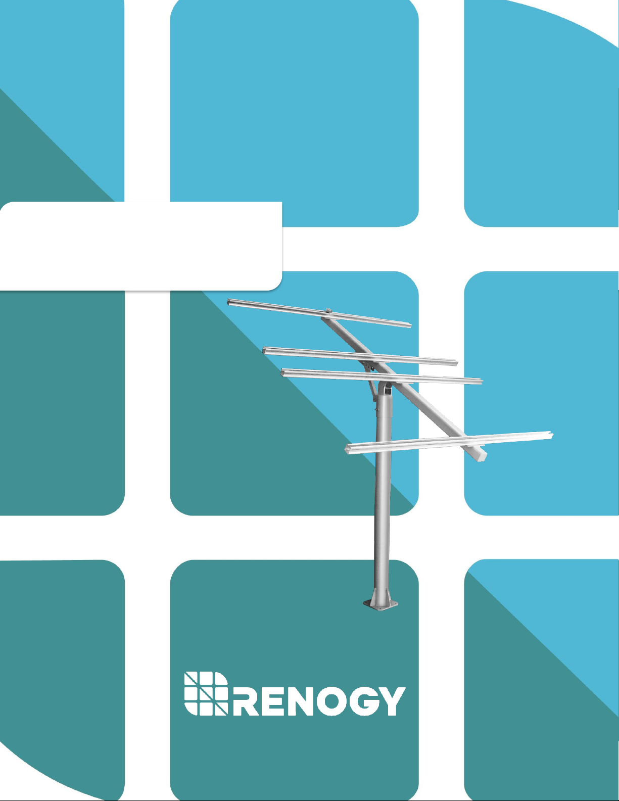
MTS-MPM
Multi-Panel Mounting System
2775 E Philadelphia St, Ontario, CA 91761
1-800-330-8678
Page 2
2
Important Safety Instructions
Please save these instructions.
This manual contains important safety, installation, and operating instructions for the hardware
system. The following symbols are used throughout the manual to indicate potentially dangerous
conditions or important safety information.
WARNING: Indicates a potentially dangerous condition. Use extreme caution when
performing this task.
CAUTION: Indicates a critical procedure for safe and proper operation of the system.
NOTE: Indicates a procedure or function that is important to the safe and proper operation
of the system.
General Safety Information
• Read all of the instructions and cautions in the manual before beginning the installation.
• Do NOT attach solar panel to multi-panel pole mount until mount is securely fit, and pole
base has been secured.
• Chance to strip nuts and bolts exists.
• Multiple people for installation is suggested.
• Do NOT substitute parts from other manufacture ring sources, doing so may void the
warranty and/or result in an unstable system
• This system is NOT possessing any compliance with residential structural codes and
should not be used in place of a system that is, if so required by local regulations
Installer Responsibilities
• Installation compliance with any applicable codes which are enforced at the installation
site.
• Installation compliance and compatibility with all system components and the environment
including but not limited to roofing, system components, etc.
• Verification that all project information is accurate
• Ensure proper array structure grounding, including each module frame and the mounting
pole. Failure may result in damage to your equipment. Do NOT rely on mounting pipe to
act as grounding rod! It is not a reliable substitute.
Page 3
3
WARNING: these instructions are intended to be used by individuals with sufficient
technical skills for the task. Knowledge and use of hand tools, measuring devices, and
torque equipment is also required
WARNING: Electrocution Hazard! Check for clearance to overhead power lines before
bringing any installation.
WARNING: Watch your hands and fingers! We make every effort to remove sharp edges
from the galvanized products. However, we still recommend installers wear gloves
when handling these mounts in order to avoid the sharp edges.
WARNING: The mount is heavy! Depending on the modules you are using, the weight
will only increase. Therefore, it is recommended to have the aid of another person
and/or lifting devices that can help install this safely. Failure to observe this warning
can hurt or kill you.
Page 4

4
Table of Contents
General Information ......................................................................................................................................... 5
Material List .......................................................................................................................................................... 5
Installation ............................................................................................................................................................. 9
Foundation .................................................................................................................................................. 10
Compatibility with Renogy Panels ..................................................................................................... 11
1- Install Base Column on the Foundation ...................................................................................... 12
2- Install Connector on Base Column ................................................................................................ 12
3- Install Main Girder and Angle Adjustment Connector .......................................................... 13
4- Install Cross Beams on Main Girder ............................................................................................. 14
5- Install Solar Panels with End Clamps and Mid Clamps ........................................................ 15
6- Check All Parts to Ensure Safety.................................................................................................... 17
Check all screws and clamps to make sure all parts are securely installed. ...................... 17
Maintenance ...................................................................................................................................................... 17
Technical Specifications ........................................................................................................................... 17
Compatibility ..................................................................................................................................................... 18
Page 5
5
General Information
The Renogy MTS-MPM is designed for off-grid applications when mounting on a roof is not ideal.
Composed of high strength steel and corrosion resistant welded components, the MTS-MPM can
support up to 400 Watts of power. The system comes complete with all fasteners to adhere panels
to the mounting surface. This system makes the installation solar systems, easy, affordable, and
quick.
Key Features
• Galvanized Steel and Anodized Aluminum Alloy construction
• High-tensile strength and corrosion free fasteners
• Precision hole positioning and alignment
• Compatible with multiple Renogy PV sizes—(4) 100W Mono, (2) 160W Mono, (1) 270W
Poly, (1) 300W Mono
• Secures most 100W-350W PV modules
• Mount up to 400W on a single pole
• Standard design can withstand up to 75mph wind
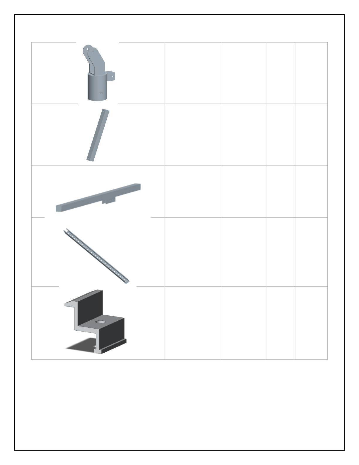
Material List
Image
Component
Size / in
Qty.
Material
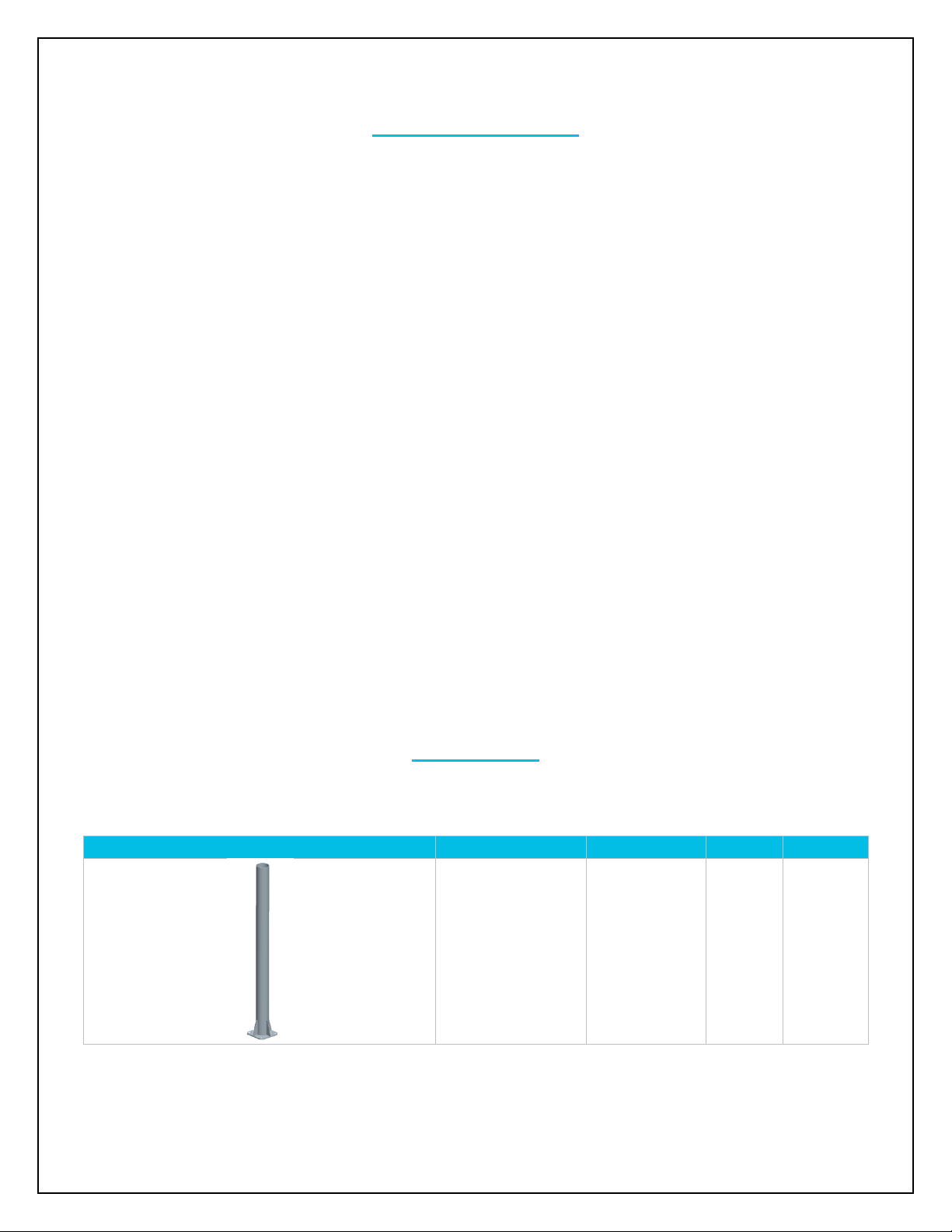
Base Column
4.3(diameter)x
59.1
1
Q235
Steel
Page 6
6
Connector
4.5(diameter)x
5.91
1
Q235
Steel
Angle Adjustment
Connector
1.2x1.2x12.8
1
Q235
Steel
Main Girder
2.4x2.4x78.8
1
Q235
Steel
Cross Beam
1.6x1.6x63.0
4 Q235
Steel
End Clamp Piece
1.5x1.6x1.6
8+(2)
spare*
H35
Aluminum
Page 7
7
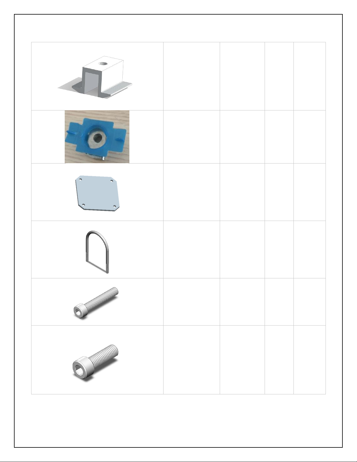
Mid Clamp Piece
1.4x1.0x2.0
4+(1)
spare*
H40
Aluminum
Strut Channel Nut
with Plastic Wing
2.0x1.3x0.7
12+(2)
spare*
Plastic
and steel
Positioning Plate
for Base Column
7.9x7.9x0.3
1
Q235
steel
U-Bolt for Base
Installation
7.1x6.0x0.4(di
ameter)
2
Q235
Steel
Socket Head
Screw
M8 x 50
14+(2)
spare*
S304
Stainless
Steel
Socket Head
Screw
M8 x 20
2+(1)
spare*
S304
Stainless
Steel
Page 8
8
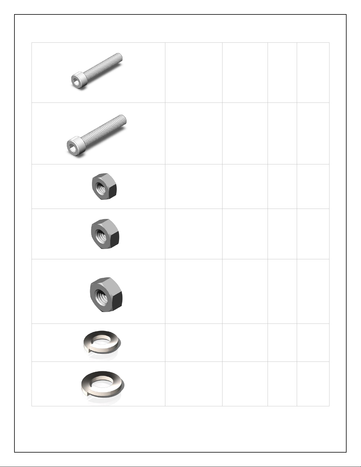
Socket Head
Screw
M10 x 20
8+(2)
spare*
S304
Stainless
Steel
Socket Head
Screw
M12 x 100
1+(1)
spare*
S304
Stainless
Steel
Hex Nut
M8
2+(2)
spare*
S304
Stainless
Steel
Hex Nut
M10
12+(2)
spare*
S304
Stainless
Steel
Hex Nut
M12
1+(1)
spare*
S304
Stainless
Steel
Split Lock Washer
M8
10+(2)
spare*
S304
Stainless
Steel
Split Lock Washer
M10
8+(2)
spare*
S304
Stainless
Steel
Page 9
9
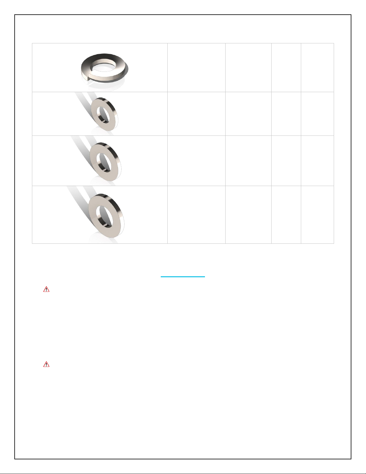
Split Lock Washer
M12
1+(1)
spare*
S304
Stainless
Steel
Flat Washer
M8
10+(2)
spare*
S304
Stainless
Steel
Flat Washer
M10
8+(2)
spare*
S304
Stainless
Steel
Flat Washer
M12
1+(1)
spare*
S304
Stainless
Steel
*Spare parts serve as safety margins for installation, spare parts quantity is not guaranteed.
Installation
Renogy assumes no responsibility for your foundation installation. Consult a local
professional for proper installation.
Recommended tools to have before installation (Not provided):
• Standard Wrench Set
• Standard Socket Set
• Allen Wrenches
• Level
• Tape Measure
• Screwdrivers
The above tools and equipment are highly recommended to have available to assist
with installation but are in no way a comprehensive list of tools. Installers feel free to
substitute comparable equipment where appropriate.
Page 10
10
Foundation
WARNING! Windy conditions can exert extreme forces on the PV array, foundation, and
mounting mast of your array.
WARNING! Keep hands clear of pinch points!
NOTE: Choose an optimum solar location that is free from obstructions such as trees and
buildings.
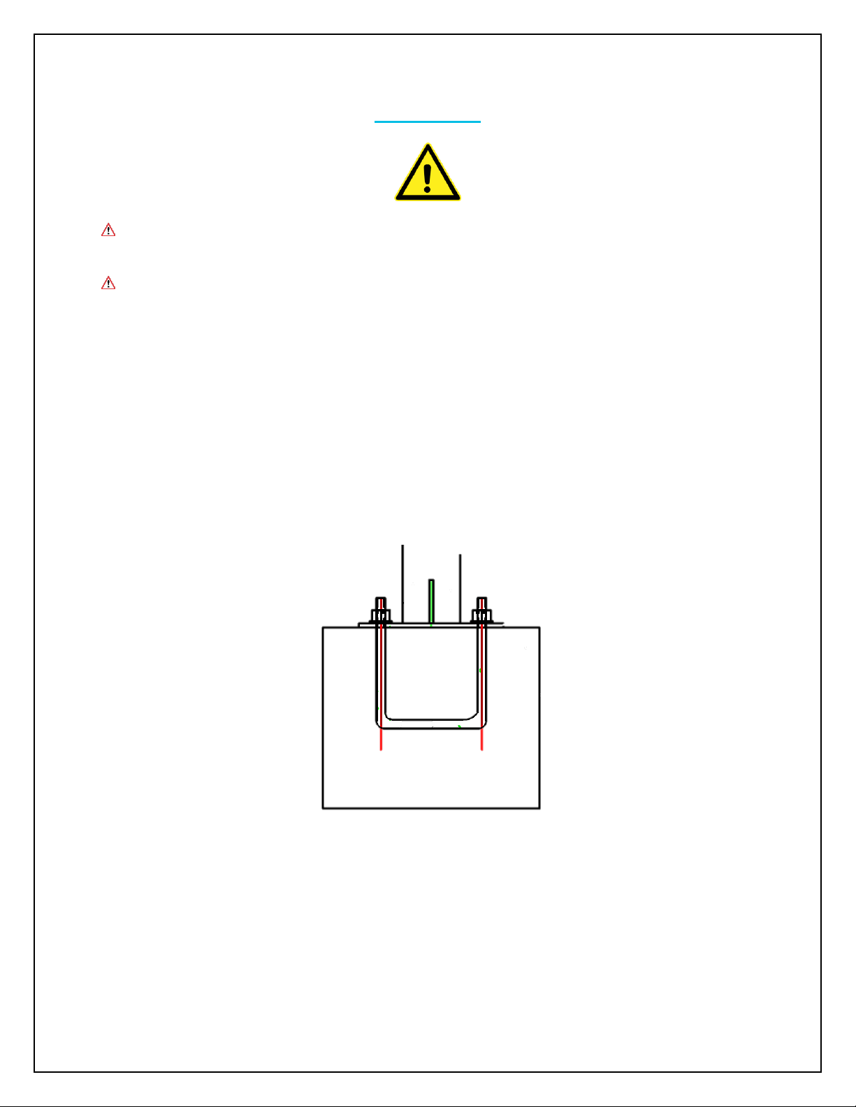
The recommend installation method involves using the provided 2 pieces of U-Bolt, positioning
plate with a cement foundation that users must create. The cement foundation recommended is
a 20” x 20” concrete block square with the positioning plate on top and U-bolt inside. The
foundation may vary depending on soil and location. It is recommended, and in some locations,
required, to seek the advice and or approval of a licensed Professional Engineer familiar with
your local codes and requirements prior to construction.
Page 11
11
Compatibility with Renogy Panels
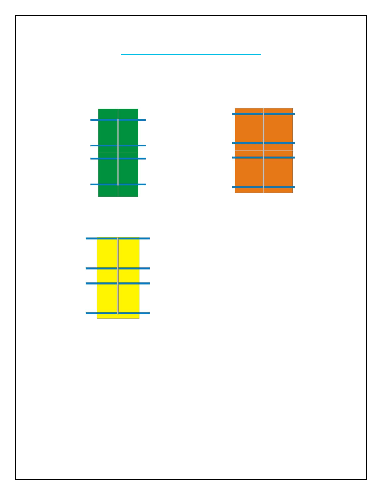
NOTE: Depending on the user, each multi-panel mount will be optimized for certain PV
module(s). In terms of Renogy arrays, the following are recommended to be affixed:
4 x 100W Mono
4 x 100W Poly
1 x 270W to 300W
NOTE: The provided end clamps are only compatible with 100W-150W panels. When
using 270W-300W panels the proper end clamps must be purchased.
Page 12
12
1- Install Base Column on the Foundation
WARNING! The mount is heavy! Depending on the modules you are using, the weight
will only increase. Therefore, it is recommended to have the aid of another person
and/or lifting devices that can help install this safely. Failure to observe this warning
can hurt or kill you.
WARNING! Keep hands clear of pinch points!
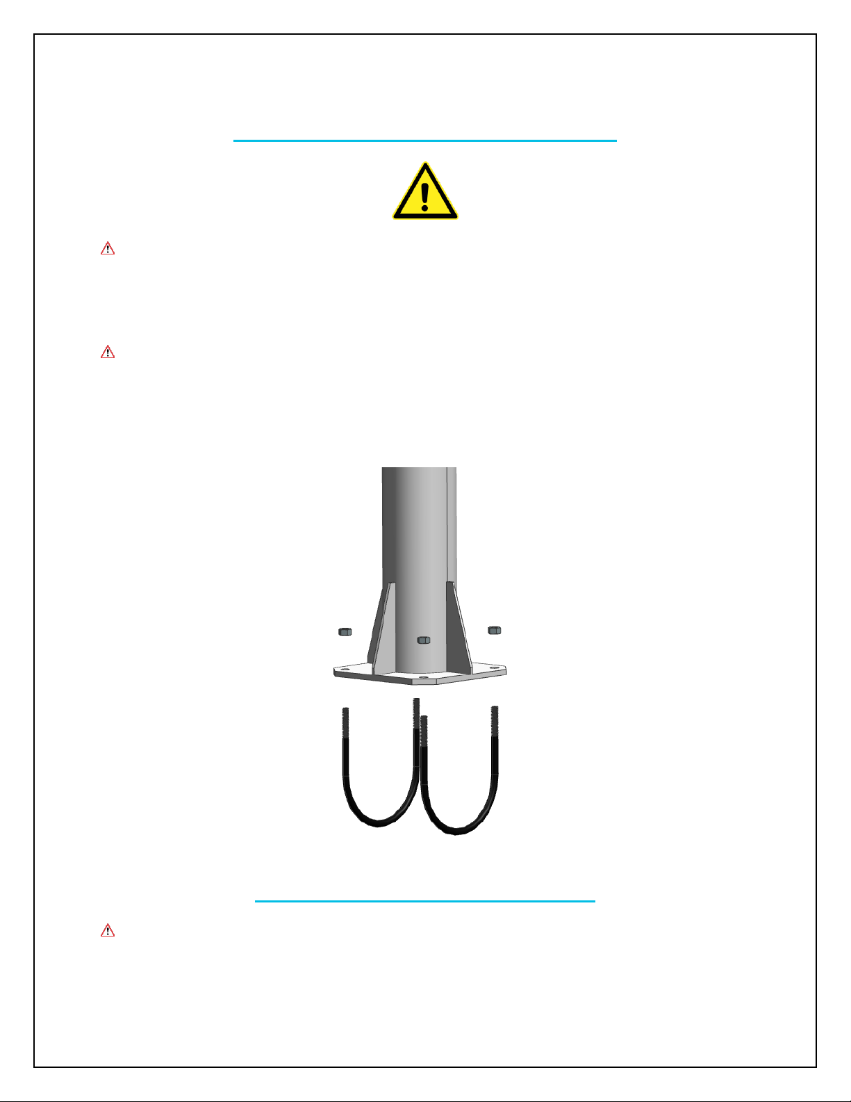
After placing the positioning plate on top and U-blots inside the concrete block,
the foundation is now complete. The next step is to place the base column on top
of the positioning plate. Use 4 pieces of M10 hex nut to tighten the base column
to the U-bolts.
2- Install Connector on Base Column
WARNING! Keep hands clear of pinch points!
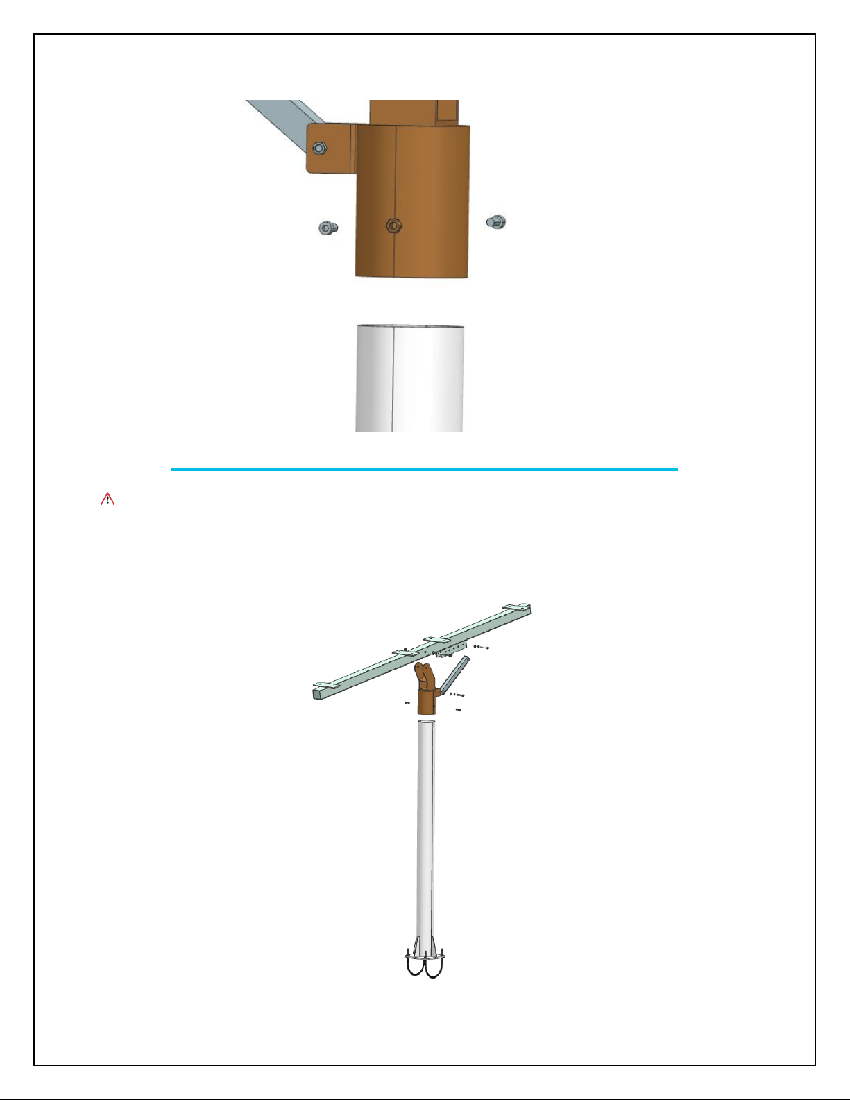
Attach the connector to the top of base column with 2 pieces of M8x20 socket
head screw and M8 hex nut.
Page 13
13
3- Install Main Girder and Angle Adjustment Connector
WARNING! Keep hands clear of pinch points!
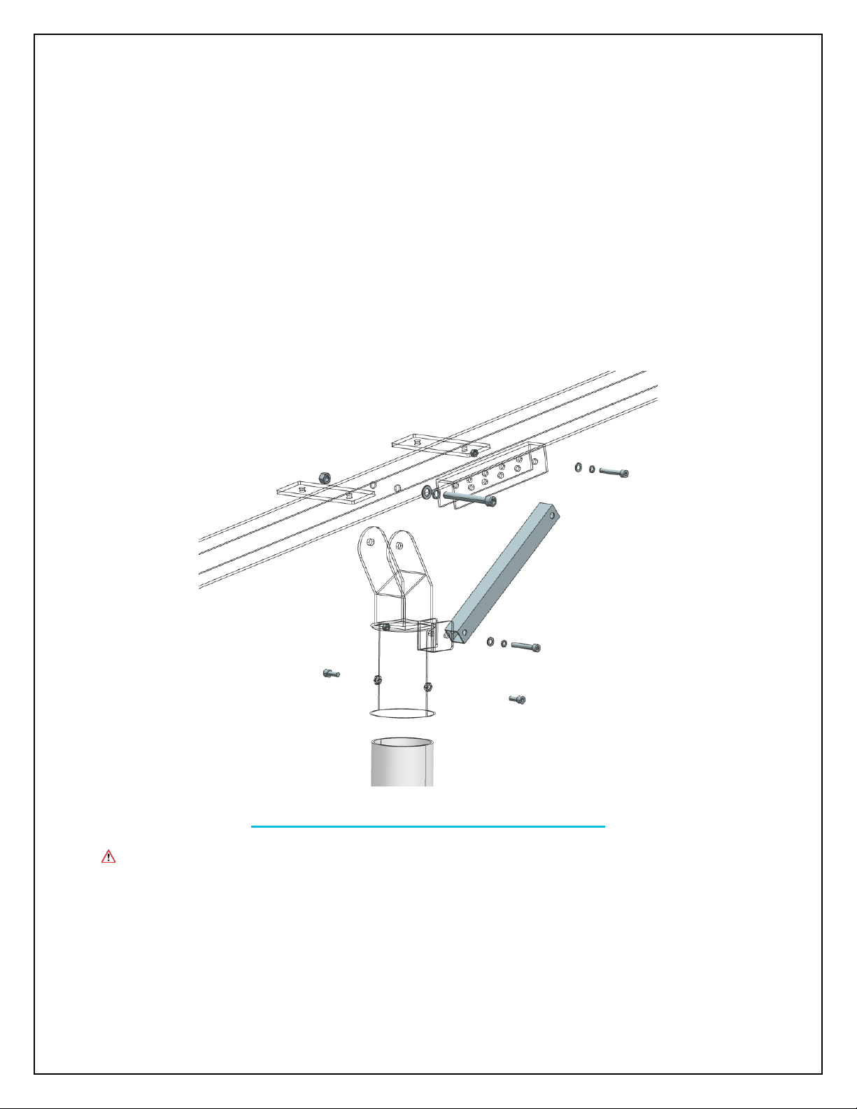
Attach the main girder and angle adjustment connector to the connector. Please
follow the next 3 steps for this part of installation.
Page 14
14
Step 1: Attach the angle adjustment connector to the connector with a M8x50
socket head screw, a M8 split lock washer, a M8 flat washer and a M8 hex nut.
Step 2: Attach the main girder to the connector with a M12x100 socket head
screw, a M12 split lock washer, a M12 flat washer and a M12 hex nut.
Step 3: Choose the desired angle from 10 to 50 degrees for the main girder by
choosing suitable installation hole. Attach the angel adjustment connector to the
main girder with a M8x50 socket head screw, a M12 split lock washer, a M8 flat
washer and a M8 hex nut.
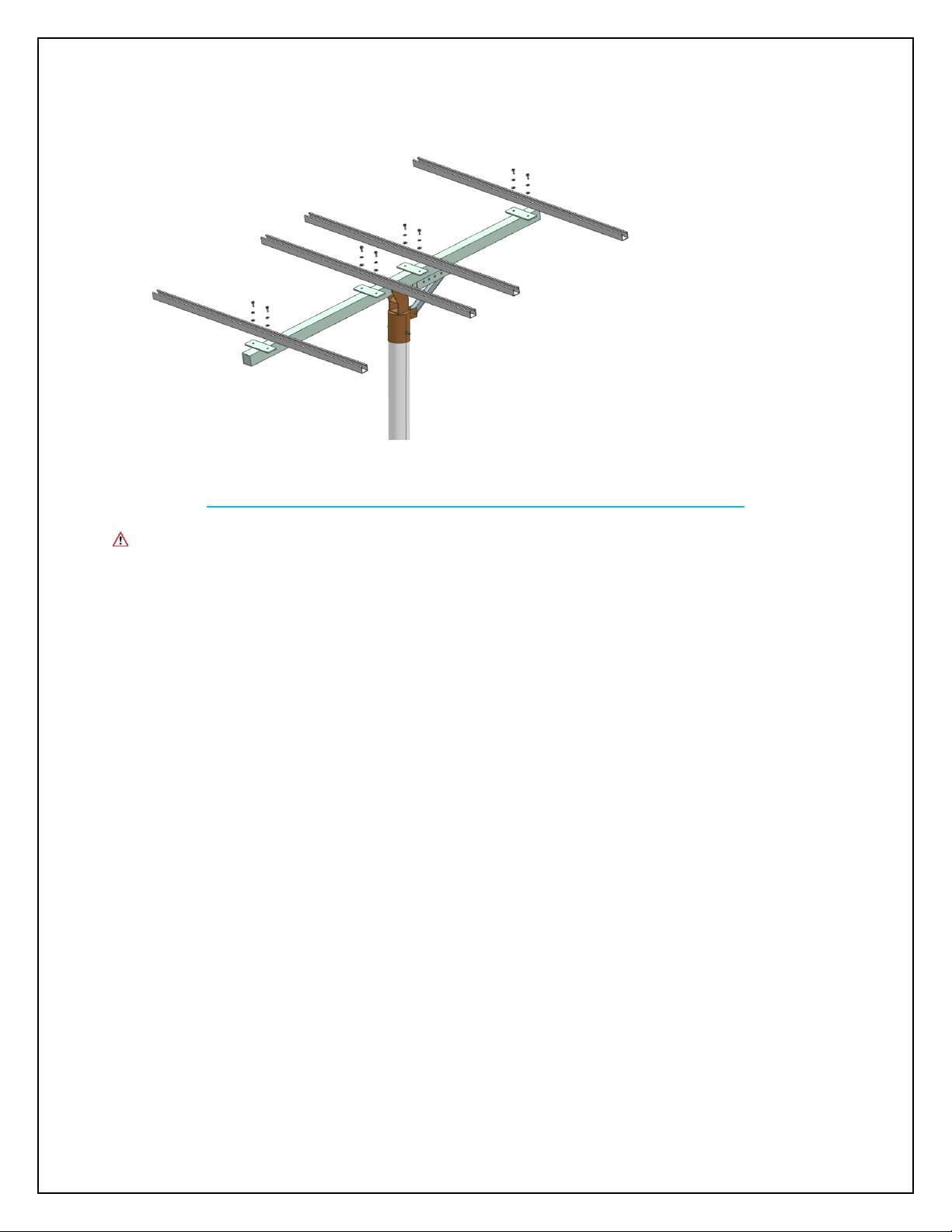
4- Install Cross Beams on Main Girder
WARNING! Keep hands clear of pinch points!
Attach cross beam to the top of main girder with 2 pieces of M10x20 socket head
screw, M10 split lock washer, M10 flat washer and M 12 hex nut. Repeat to
install all 4 cross beams.
Page 15
15
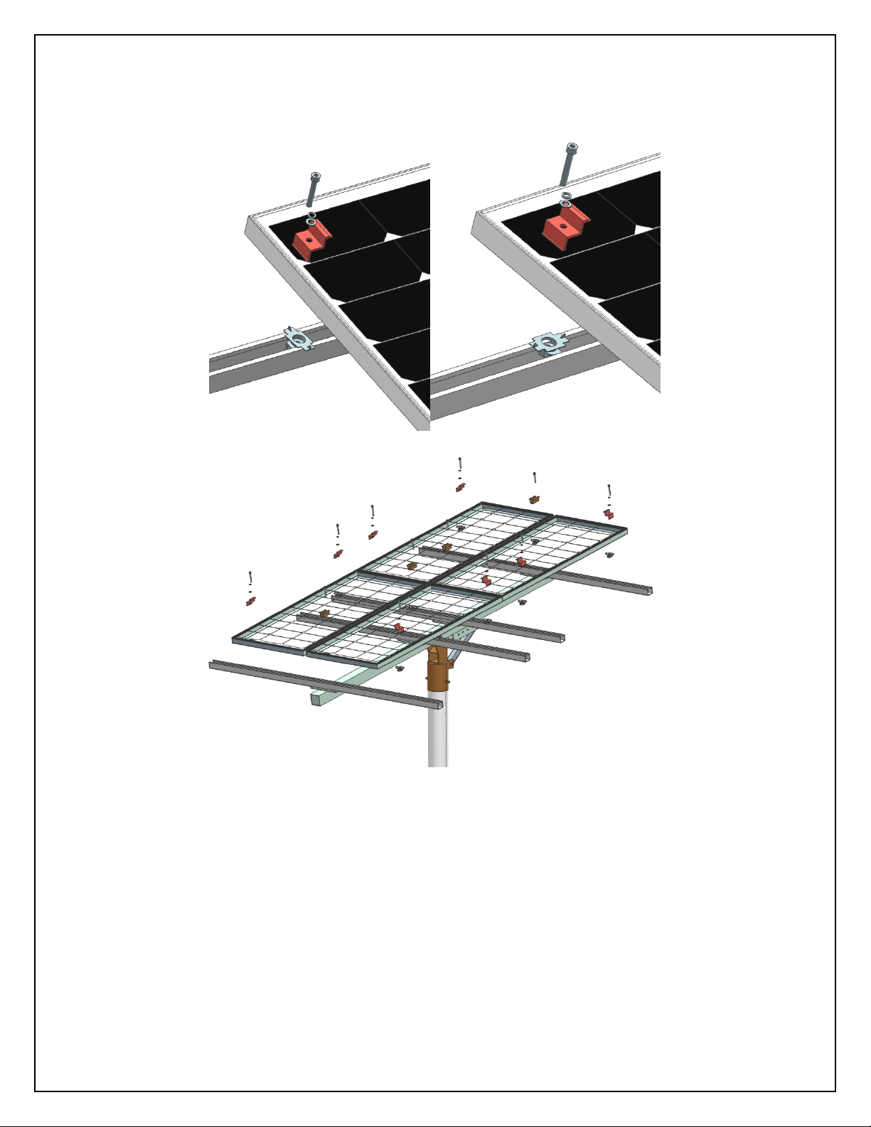
5- Install Solar Panels with End Clamps and Mid Clamps
WARNING! Keep hands clear of pinch points!
Step 1: Push the strut channel nut with plastic wing into the cross beam from
side. Then turn the plastic wing 90 degrees to align with the cross beam.
Step 2: Put solar panel in the desired position on top of the cross beam.
Step 3: Put end clamp and mid clamp on top of strut channel nut, fasten with a
M8x50 socket head screw, a M8 split lock washer, a M8 flat washer
Step 4: Repeat step 1 to 3 for all end clamps and mid clamps until all panels are
securely installed
Page 16
16
Page 17
17
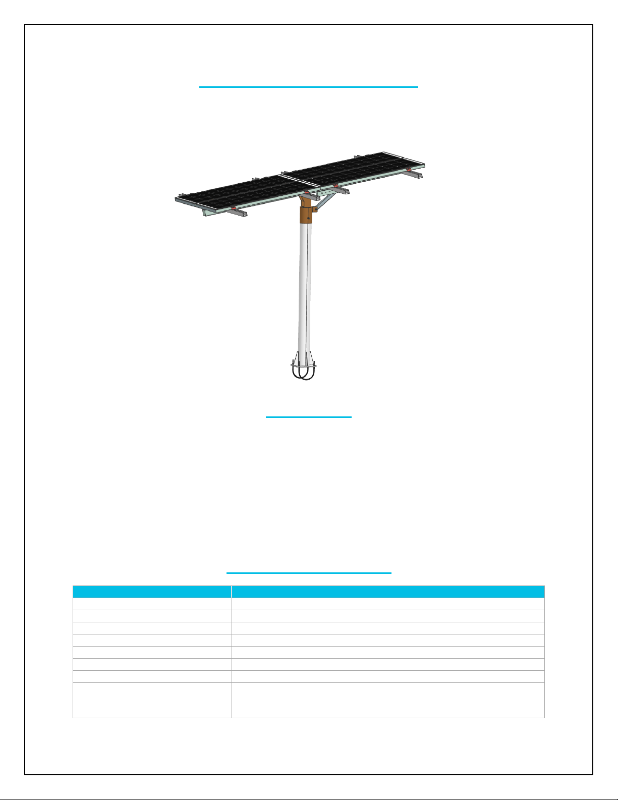
6- Check All Parts to Ensure Safety
Check all screws and clamps to make sure all parts are securely installed.
Maintenance
You should be inspecting your multi-panel mount once per year. While inspecting, make sure of
the following:
1. Ensure hardware is tight, tighten if need be
2. Check all wiring connections for tightness and water proof integrity
3. Check for any damage
4. Inspect welds for any visible cracking or other signs of fatigue
5. Check the foundation for any signs of damage or cracking
Technical Specifications
Pole Height
59.1 in
Array Height
62.6 to 74.5 in
Mounting Method
U-bolt in concrete foundation (U-bolt provided)
Tilt Angles
10 to 50°
Maximum Wind Speed
72 mph
Max Snow Pressure
23, 940 psf
Gross Weight
165 lb
International Compliant
Standards
GB 50009 – 2012 (Wind Rating)
GB 50009 – 2012 (7.1.1) (Snow Rating)
Page 18
18
GB50009 – 2012 (Load Structure for Building Structures
GB50011- 2010 (Code for Seismic Design of Buildings)
GB50017 – 2003 (Code for Design of Steel Structures)
GB50018 – 2002 (Cold – formed thin – Walled Steel Structure
Technical Specification
GB50429 – 2007 (Code for Design of Aluminum Alloy Structures)
GB50797 – 2012 (Design Code for Photovoltaic Power Station)
Warranty
1 year
Compatibility
RENOGY Solar Module
Compatibility*
RNG-10D-SS
INCOMPATIBLE
RNG-20D-SS
INCOMPATIBLE
RNG-30D-SS
INCOMPATIBLE
RNG-50D-SS
INCOMPATIBLE
RNG-80D-SS
COMPATIBLE
RNG-100D
COMPATIBLE
RNG-100D-SS
COMPATIBLE
RNG-100D-SSP
COMPATIBLE
RNG-100D-R
COMPATIBLE
RNG-100MB
COMPATIBLE
RNG-160D-SS
COMPATIBLE
RNG-300D
COMPATIBLE
RNG-50P
INCOMPATIBLE
RNG-100P
COMPATIBLE
RNG-270P
COMPATIBLE
* Larger panel may need suitable clamps for installation, which are not provided with product
 Loading...