

Page 1
1
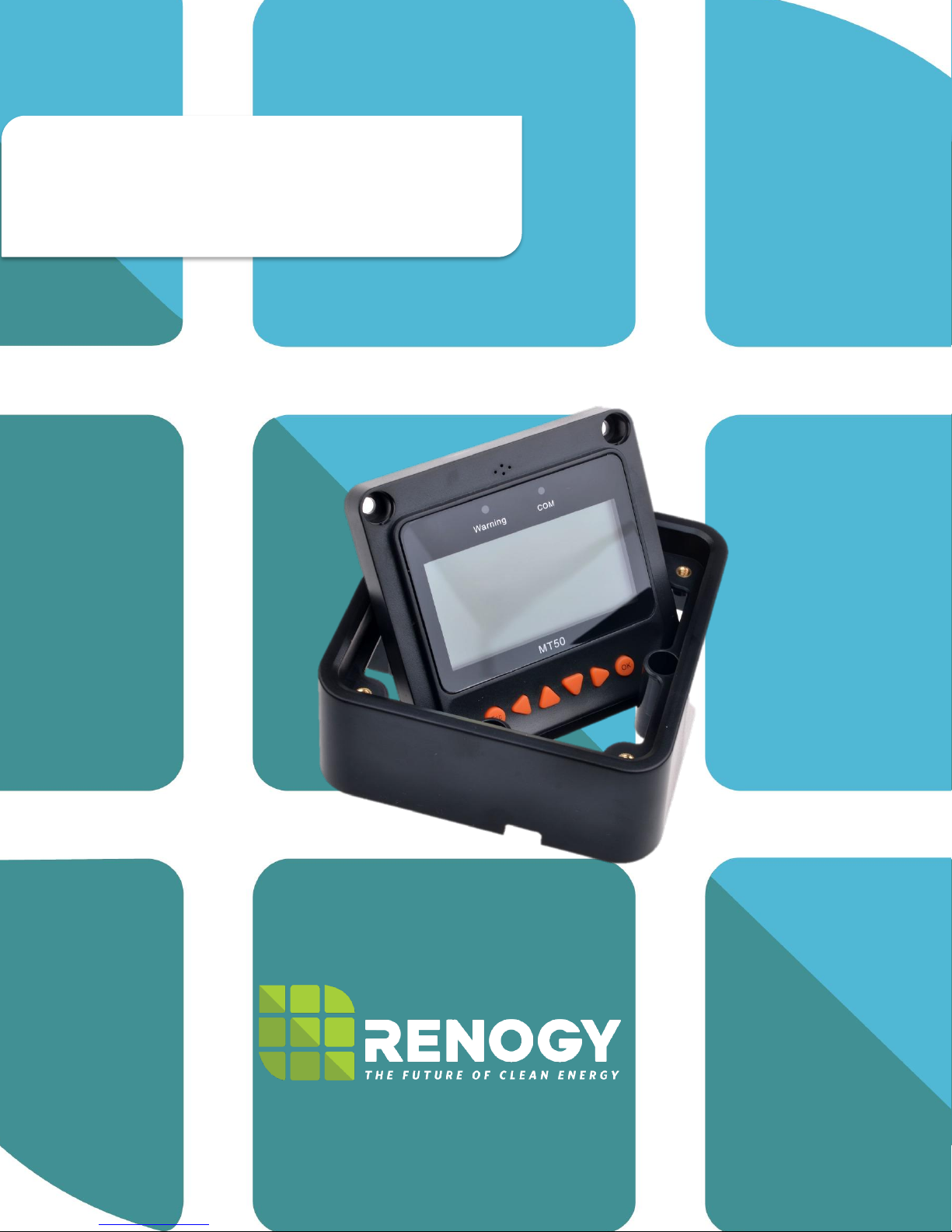
MT-50 Remote Tracer Meter
RENOGY Remote Tracer Meter for Commander
Series and ViewStar Series Charge Controllers
2775 E. Philadelphia St., Ontario CA 91761
1-800-330-8678
Version 2.0
Page 2

2
General Information ...................................................................................................... 3
Identification of Parts ................................................................................................... 4
Installation ..................................................................................................................... 5
Frame Wall Mount Installation .................................................................................. 5
Flush Wall Mount Installation ................................................................................... 6
Operation ....................................................................................................................... 6
Menu Display ............................................................................................................. 6
1. Monitoring ........................................................................................................... 7
2. Device Info .......................................................................................................... 9
3. Test Operation .................................................................................................... 9
4. Control Parameters ............................................................................................ 9
5. Load Set ............................................................................................................ 11
6. Device Parameters ........................................................................................... 13
7. Device Password .............................................................................................. 13
8. Factory Reset .................................................................................................... 14
9. Failure Info ........................................................................................................ 14
10. Meter Parameters ............................................................................................. 14
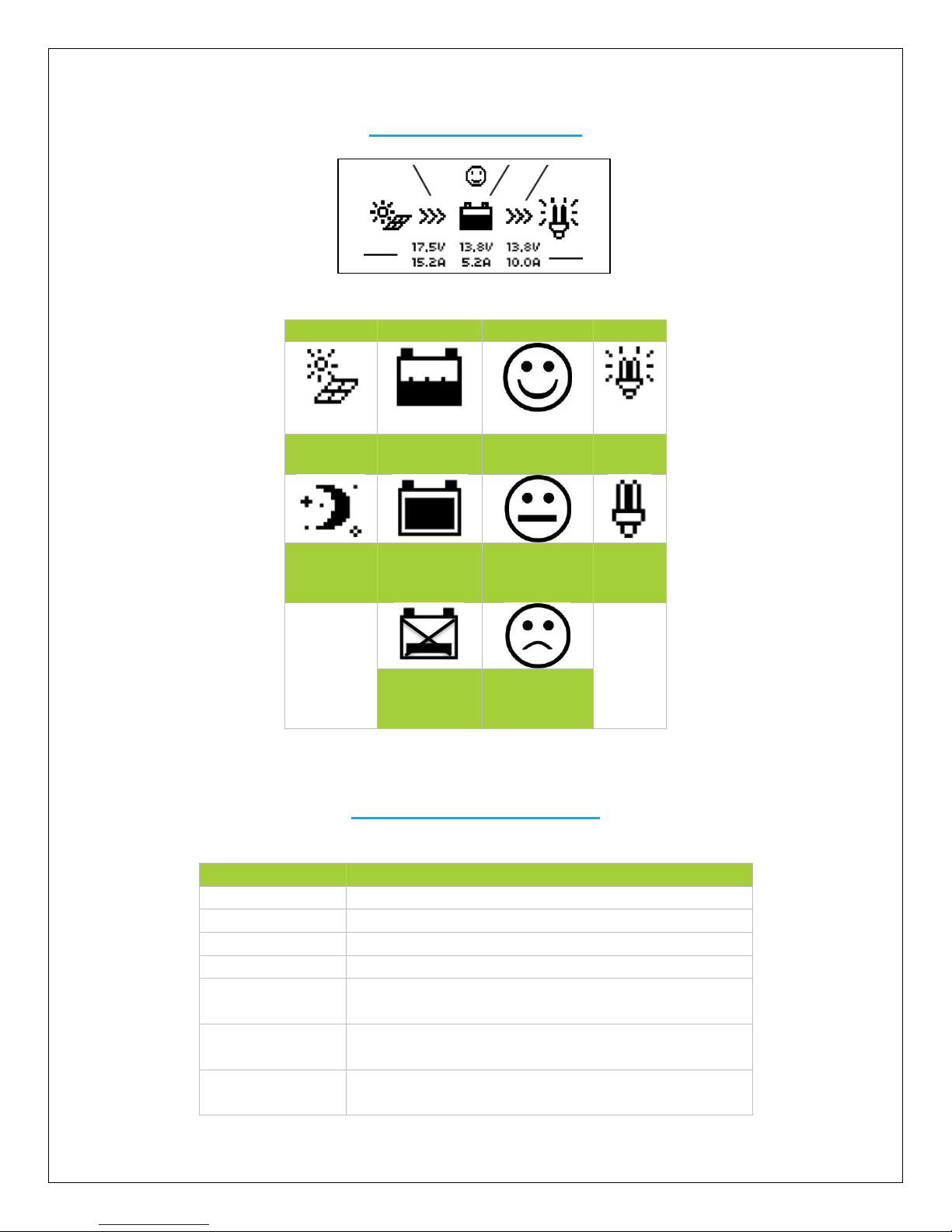
System Status Icons ................................................................................................... 15
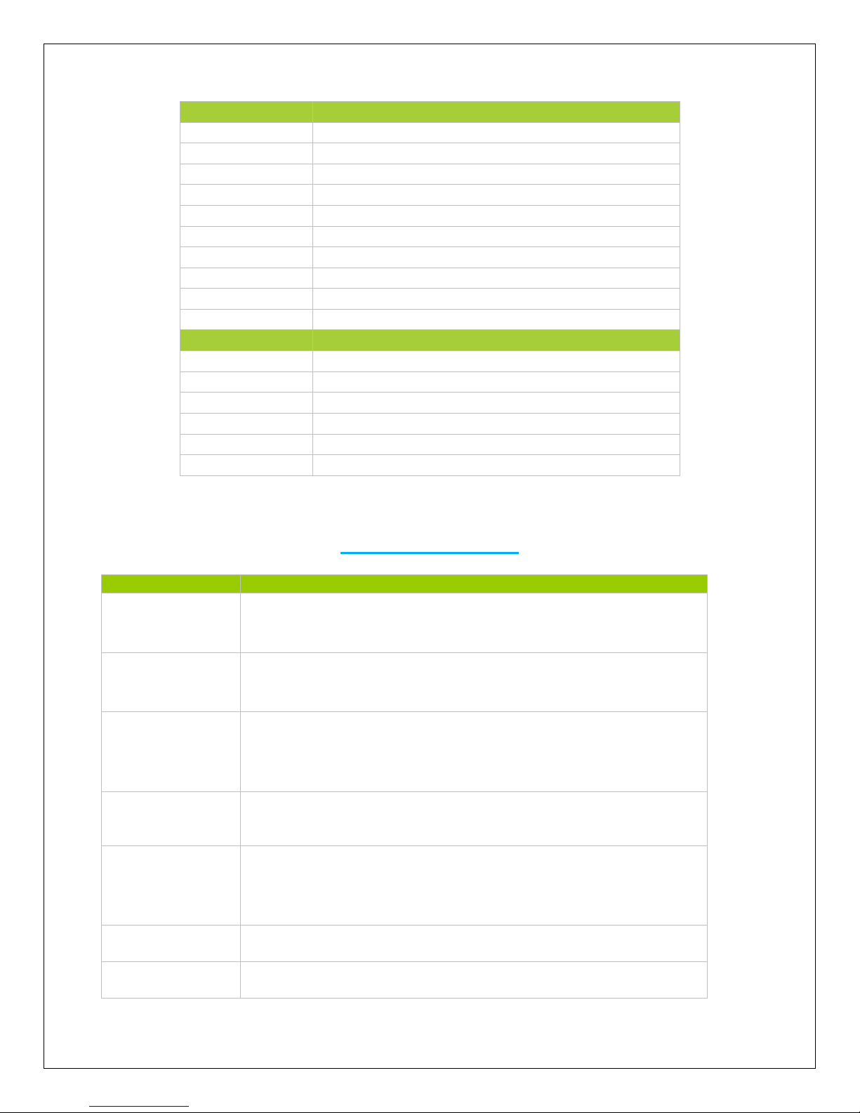
System Status Glossary ............................................................................................. 16
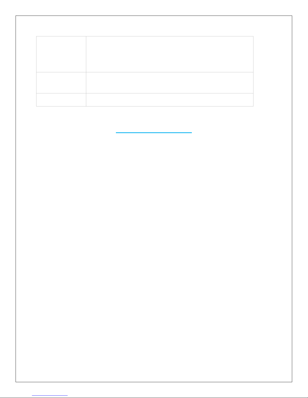
Failure Information...................................................................................................... 17
Device Considerations ............................................................................................... 17
Warning Indicator .................................................................................................... 17
Telecommunication Port ........................................................................................ 18
Battery Level Flashing ............................................................................................ 18
Battery capacity AH ................................................................................................ 18
Troubleshooting .......................................................................................................... 18
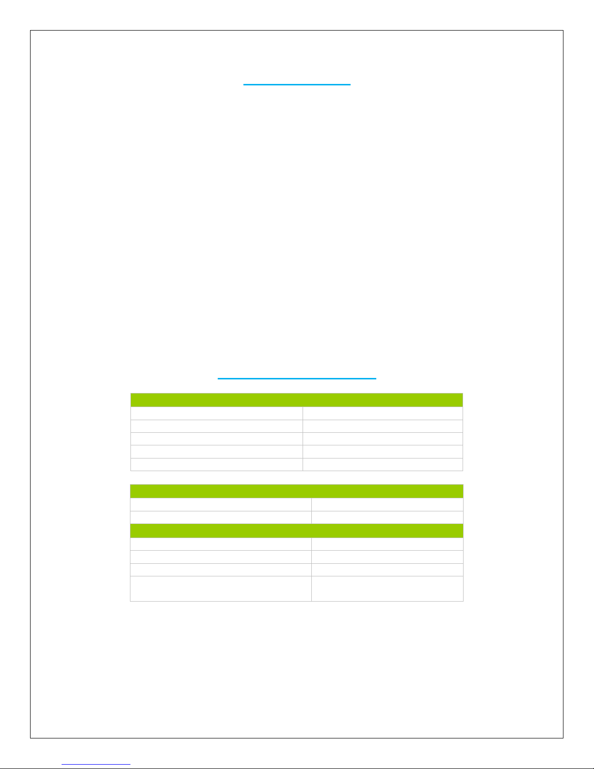
Technical Specifications ............................................................................................ 19
Mechanical Parameters .......................................................................................... 19
Temperature Parameters ........................................................................................ 19
Electrical Parameters .............................................................................................. 19
Charging Parameters .............................................................................................. 19
Threshold Voltage Parameters ............................................................................... 20
Interface Pin Numbers ............................................................................................ 20
CAD Dimensions ..................................................................................................... 21
Table of Contents
Page 3

3
Important Safety Instructions
Please save these instructions.
This manual contains important safety, installation, and operating instructions for the unit. The
following symbols are used throughout the manual to indicate potentially dangerous conditions
or important safety information.
WARNING: Indicates a potentially dangerous condition. Use extreme caution when performing
this task.
CAUTION: Indicates a critical procedure for safe and proper operation of the controller
NOTE: Indicates a procedure or function that is important to the safe and proper operation of the
controller.
General Safety Information
• Inspect the MT-50 after it is delivered. If any damage, notify the company immediately. A
photograph might be helpful as well.
• Read all directions and cautions in the manual before installation
• Keep the MT-50 away from rain, severe dust, and electromagnetic interference.
General Information
The Renogy MT-50 is a new generation meter compatible with the Commander Series and
ViewStar Series charge controllers. It is a self-diagnostics meter ideal for monitoring and
displaying the current solar system status information and any error indications the system might
be experiencing. The information is displayed on a backlit LCD display and is easily navigated
using the buttons on the meter. The MT-50 could also be flush mounted on a wall or flat surface
using the mounting frame provided.
NOTE: The MT-50 is not compatible with the Commander 60A charge controller.
Key Features
• Large backlit LCD display
• Compatible with multiple Commander Series (20A/40A) and ViewStar Series
(10A/20A/30A) charge controllers
• Real-time monitoring and graphical display
• Customizable parameters for charge control and load control
Included Components
• Wall Mounting Frame
• 6.5 foot cable
• 4 x ST4.2X32 self-tapping screws
Page 4
4
Identification of Parts
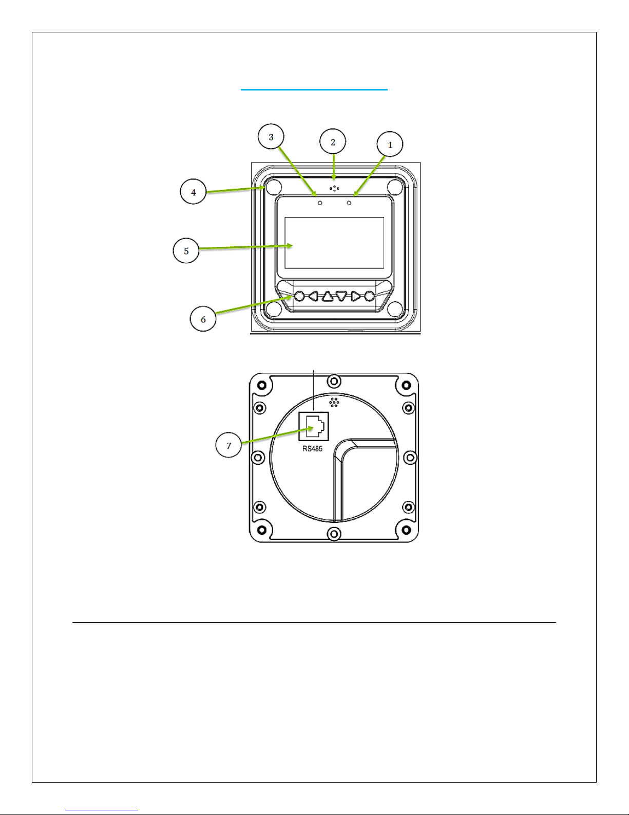
Key Parts
1. Communication Indicator (Green)
2. Alarm Sound port (Alarm will be discontinued in new models)
3. Warning Indicator (Red)
4. 4 X Mounting Holes
5. Display Screen
6. Navigation Buttons
7. RS485 Port
Page 5
5
Installation
WARNING: BEFORE drilling, make sure there are no electrical components or other obstacles
that may interfere with installation on the other side of the mounting surface.
CAUTION: Before installing the MT-50, apply power and make sure the meter is working properly.
Resolve any issues before installing the meter and the meter cable.
The MT-50 can be mounted in two ways: Frame Wall Mount or in a Flush Wall Mount. A plastic
mounting frame has been included for the purpose of Frame Wall Mounting. If Flush Wall
Mounting then the MT-50 faceplate sits flush with the mounting surface and the body of the meter
would be able to rest comfortably in a hole cut-out on the mounting surface.
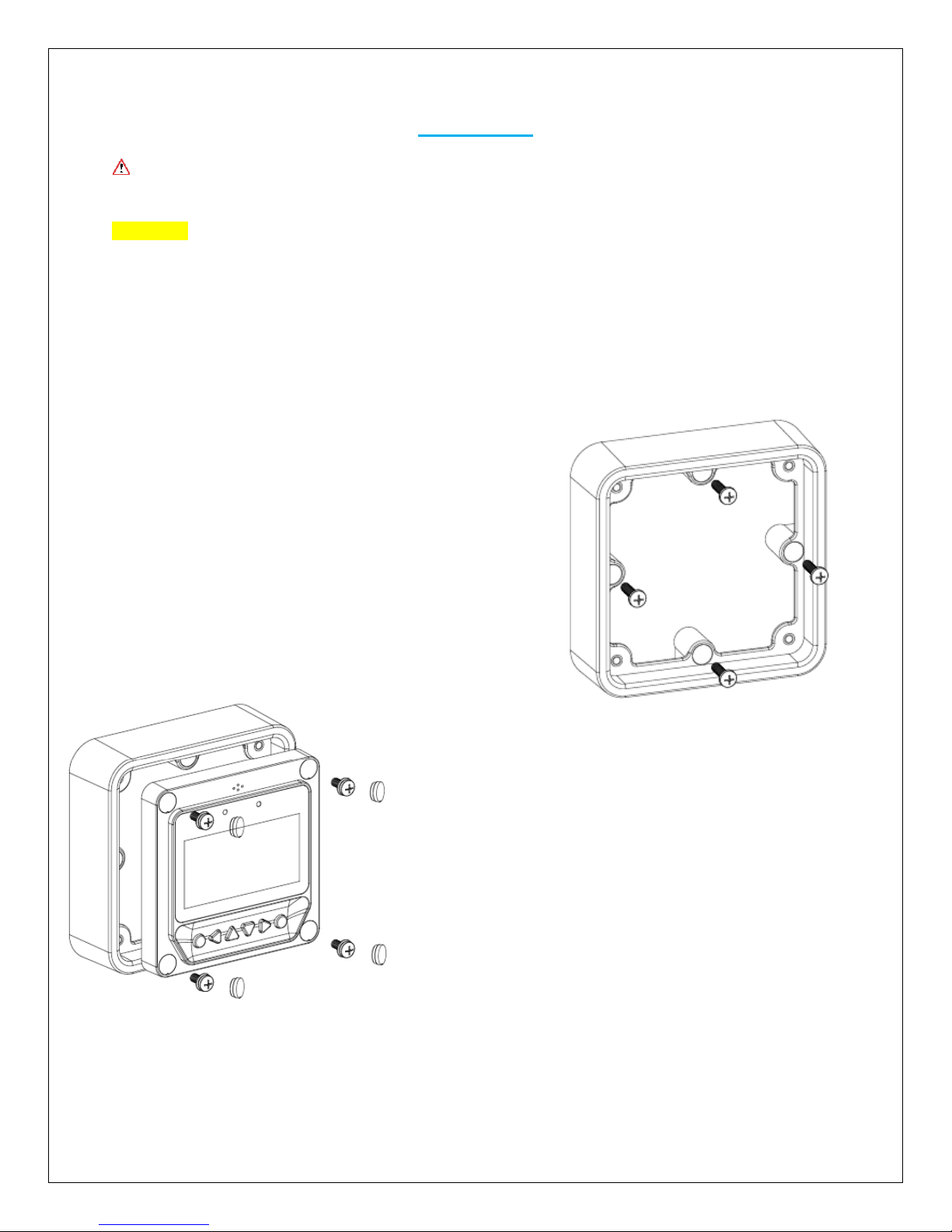
Frame Wall Mount Installation
When frame mounting, the MT-50 Tracer will be utilizing
the provided frame and be mounted on a wall or surface.
No cut-outs are required for the surface with the
exception of the 4 x screw holes.
1. Locate and drill the screw holes based on the
mounting frame dimension and erect the plastic
expansion bolts on the wall.
2. Use 4 x ST4.2x32 self-tapping screws to fix the
frame.
3. Use 4 x M4x8 pan head screws to mount the MT50 front to the frame
4. Mount the 4 associated screw plugs into the screw
holes
5. Plug the meter in and verify the meter powers up
and displays the appropriate data. Troubleshoot if
necessary.
Page 6
6
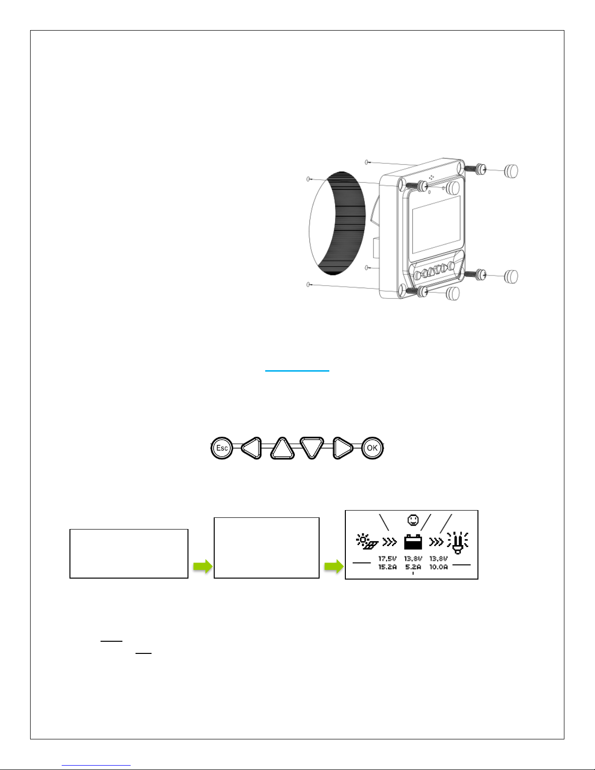
Flush Wall Mount Installation
This is a low-profile installation. The faceplate of the MT-50 sits flush with the mounting surface
or wall and the body of the meter rests in a hole cut-out on the mounting surface. The meter
wiring is concealed behind the mounting surface, or the interior of the wall.
1. Locate and drill screw holes based
on the installation size of the surface.
Level the faceplate and remove a
hole-cutout.
2. Use 4 x M4x8 cross recessed pan
head screws with the M4 nuts to
mount the MT-50 surface onto
surface.
3. Mount and use white plugs in the
screw holes.
Operation
NOTE: The MT-50 is not compatible with the Commander 60A charge controller.
The following keys are used to cycle through the screens or adjust the parameters on the tracer:
Once the Tracer Meter is connected, the user will see welcome screen followed by a device info
screen, before settling on the Default Screen.
Menu Display
Press ESC to access the main menu, and utilize the up and down keys to maneuver through the
menu. Select OK to choose an option
NOTE: In some models, you might be prompted to enter a password. Simply put “0” all the way
through and press enter.
Welcome
VS2024BN
Rate.Vol: 24V
Char.Cur: 20A
Disc.Cur: 20A
Page 7
7
NOTE: To customize charge parameters, Battery Type must be set to USER, under 4. CONTROL
PARAMETERS
NOTE: The values found in your controller are default values and will not necessarily match the
ones listed. The values on this table are to show the user what the different screens are used for.
1. Monitoring
NOTE: Use the up and down arrows to maneuver through the monitoring menus. The left and
right arrows indicate submenus and display further information regarding the system
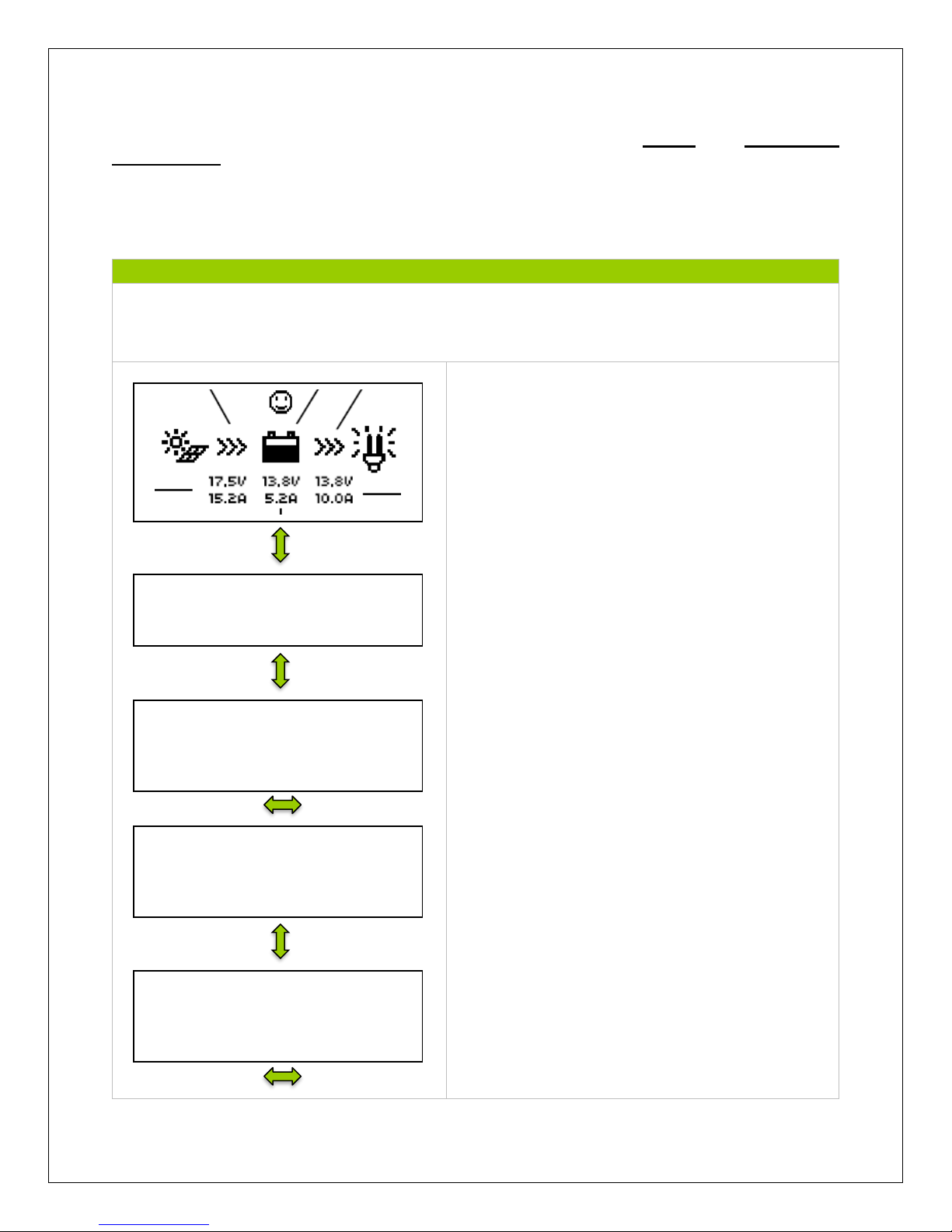
The Default Screen displays information regarding
the PV module, Battery, and Load. The PV module
indicator will have a sun or a moon depending on
the time of day. The face will indicate normal
system behavior in terms of the battery.
The screen displays the Charge Controller Model
Number, followed by the Date and Time.
The kilowatt hours accumulated in a day, Month,
and total since the controller has been turned on
NOTE: Once the battery is disconnected, the values
are reset to 0 unless there is an external battery
installed on the controller face
Same as above but regarding discharged energy
Demonstrates the battery’s Voltage, Amperage,
and State of Charge (SOC).
NOTE: The Battery SOC% is an estimation
based on the charging voltage.
Battery
Voltage: 0.00 V
Current: 0.00 A
SOC: 0.05 %
Discharge Energy
Day: 0.00 kWh
Month: 0.00 kWh
Total: 0.05 kWh
Charge Energy
Day: 0.00 kWh
Month: 0.00 kWh
Total: 0.05 kWh
VS2024BN
Jan-01-2015
04:40:44
Page 8
8
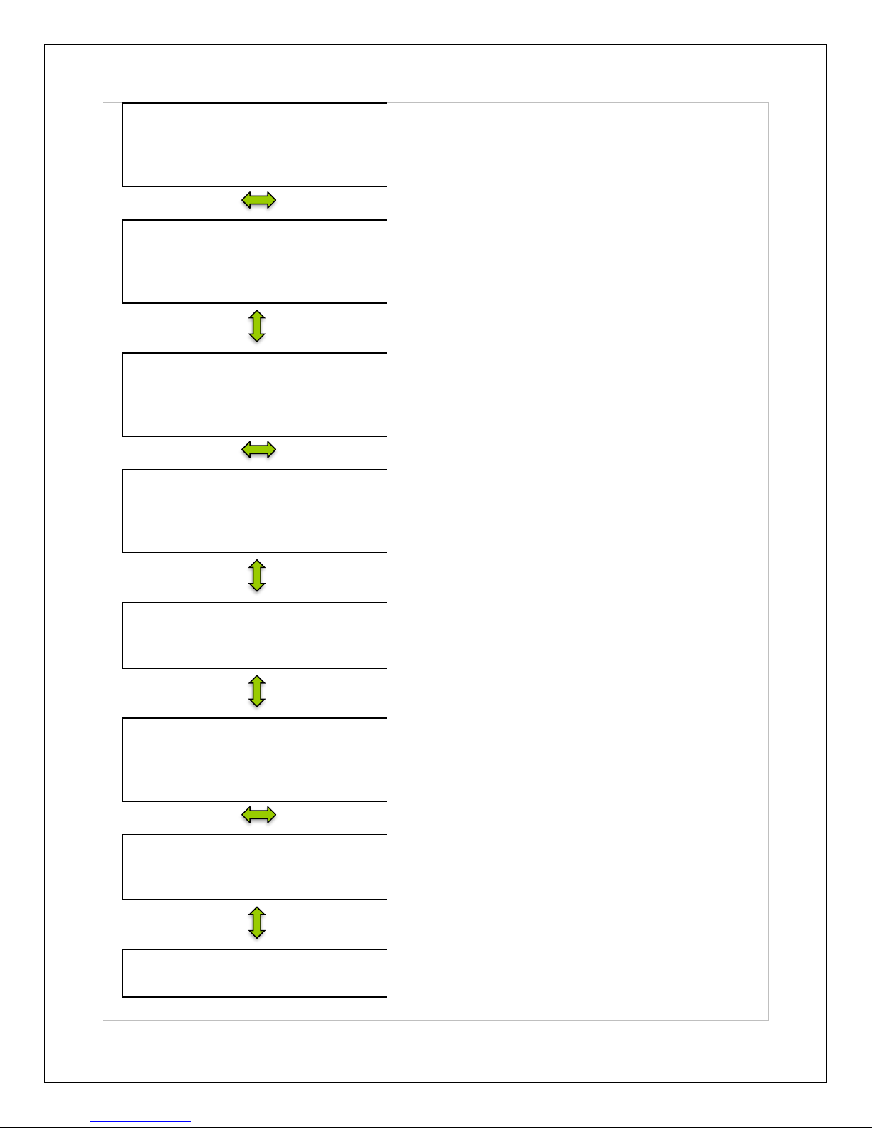
Demonstrates Battery Temperature, the Max.
Voltage detected and the Minimum Voltage
Detected by the Battery.
This screen gives the user a visual of battery
status beyond voltage, temperature, and
amperage. The user can see if they battery is
charging, the energy flow, and if there are any
faults In the system.
Looks at PV voltage, current, and power
generated.
Demonstrates PV status in terms of it PV state,
whether there is a fault detected, and the mode of
charge.
The charge controller’s temperature and status is
displayed.
Displays the current Load Voltage, Current, and
Power generated in kilowatt hours.
Indicates whether the load is on or off and whether
it is experiencing any error.
Determines whether the user wants to manually
control the paramaters of the Load.
NOTE: If timers are on, then it will display that
screen as opposed to this screen.
Manual Control
Default: Off
Load
Work: OFF
Fault: Yes
Load
Voltage: 000.0 V
Current: 000.0 A
Power: 000.0 kWh
Controller
Temperature: 000.0 °C
Status: Normal
PV
Work: Disconnect
Fault: No
Mode: PWM
PV
Voltage: 0.0 V
Current: 0.0 A
Power: 0.0 W
Battery
Charge: No Charge
Energy: Normal
Fault: No
Battery
Temperature: 0.00 °C
Max Voltage: 0.00 V
Min Voltage: 2.4 V
Page 9
9
2. Device Info
NOTE: Use the up and down arrows to maneuver through the monitoring menus. The left and
right arrows indicate submenus and display further information regarding the system
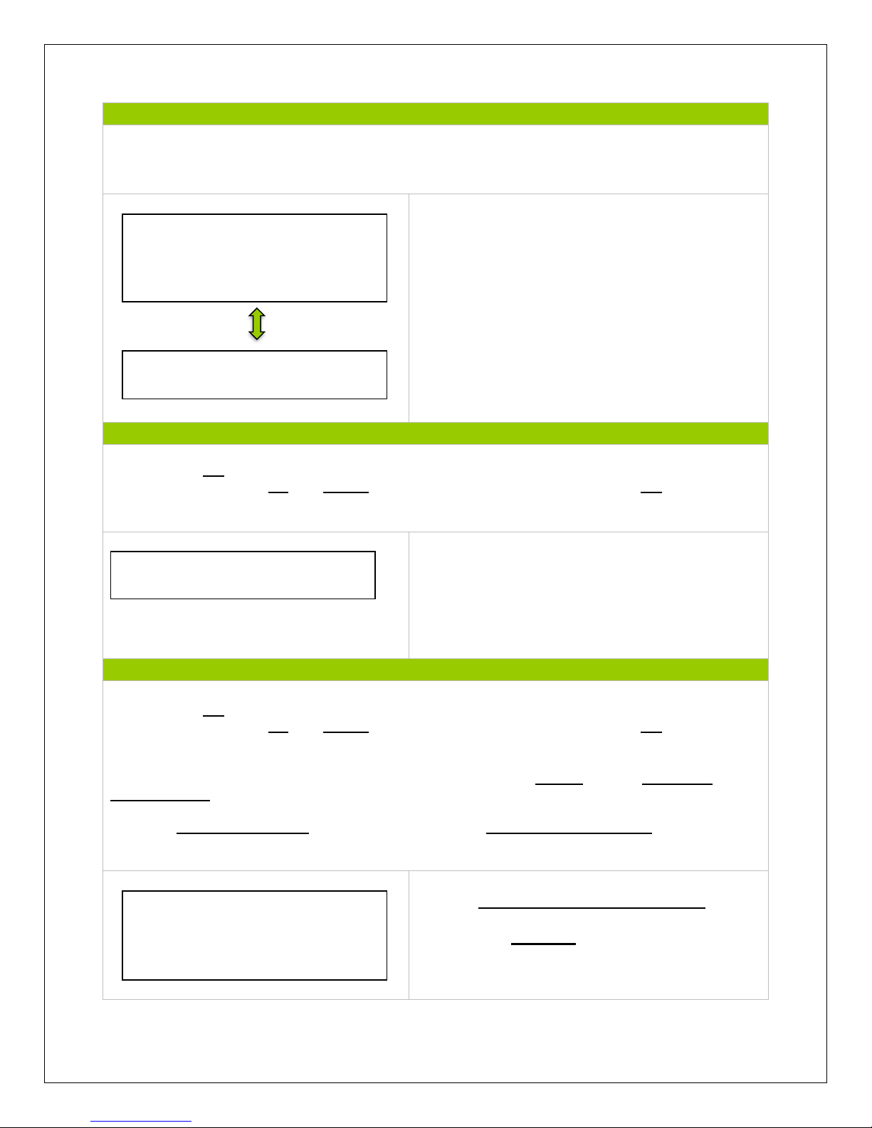
Displays device info for the charge controller and
the next menu displays the charge controller name
and screen number.
3. Test Operation
NOTE: Press OK to change from reading mode to parameter setting mode. Once the parameter
is highlighted, use the UP and DOWN arrows to adjust the setting and press OK once again to
save the setting.
The test operation is used for the load terminal and
determines whether the output is normal. It does
not affect the working-load settings (if there are
any preset) and upon turning the test operation
on/off, the screen will save and exit.
4. Control Parameters
NOTE: Press OK to change from reading mode to parameter setting mode. Once the parameter
is highlighted, use the UP and DOWN arrows to adjust the setting and press OK once again to
save the setting.
NOTE: To customize charge parameters, BATT must be set to USER, under 4. CONTROL
PARAMETERS
NOTE: A Control Parameters table can be found under Technical Specifications for parameter
boundary limits.
Choose Gel, Sealed, Flooded or User battery
and modify the Amp-hours(Ah) if necessary.
Choose from 1-999 Ah.
VS2024BN
SN: 16 digit code
VS2024BN
Rate.Vol: 24V
Char.Cur: 20A
Disc.Cur: 20A
Test Operation
VS2024BN: ON
Battery Type
Sealed
Battery AH
200AH
Page 10
10
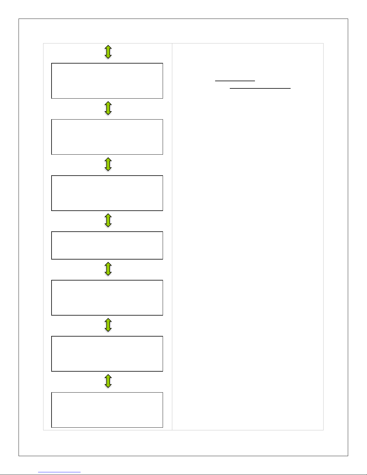
Temperature fluctuation can affect performance in
the system. Therefore, the purpose of temperature
compensation is to adjust the performance of the
system to keep the system functioning normally.
Choose from 0mV to -9mV
Choose between 12V, 24V or AUTO for rated
battery voltage.
Default parameters for over-voltage disconnect
and charge limit.
Default parameters for over-voltage reconnect
and equalization charge rate.
Default Parameters for Boost and Float Charge
Default parameters for Boost reconnection and
Low voltage reconnect
Default parameters for under voltage reconnect
and under voltage warning
Default parameters for low voltage disconnect and
the discharge limit.
Low Voltage Disconnect
11.1 V
Discharge Limit
10.6 V
Under Voltage Reconnect
12.2 V
Under Voltage Warning
12.0 V
Boost Reconnect
13.2 V
Low Voltage Reconnect
12.6
Boost Charge
14.4 V
Float Charge 13.8 V
Over Voltage Reconnect
15.0 V
Equalization Charge
14.6 V
Over Voltage Disconnect
16.0V
Charge Limit
15.0 V
Temp Comp. Coeff
-3mV/°C/2V
Rated Voltage
Auto
Page 11
11
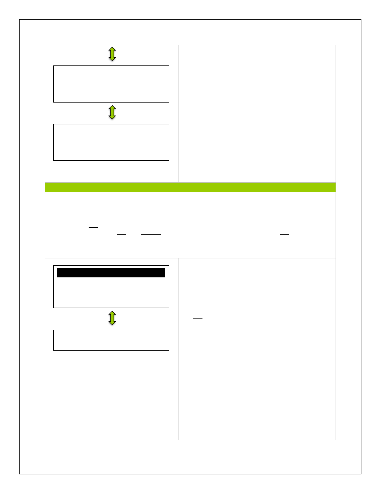
If using the SOC for battery management, then
these parameters let the Charge Controller/Tracer
know the SOC of the battery based on these
boundary limits.
NOTE: This function will be discontinued in future
models.
Set a time for how long equalization and boost
charges occur.
5. Load Set
NOTE: Use the up and down arrows to maneuver through the monitoring menus. The left and
right arrows indicate submenus and display further information regarding the system
NOTE: Press OK to change from reading mode to parameter setting mode. Once the parameter
is highlighted, use the UP and DOWN arrows to adjust the setting and press OK once again to
save the setting.
ESC
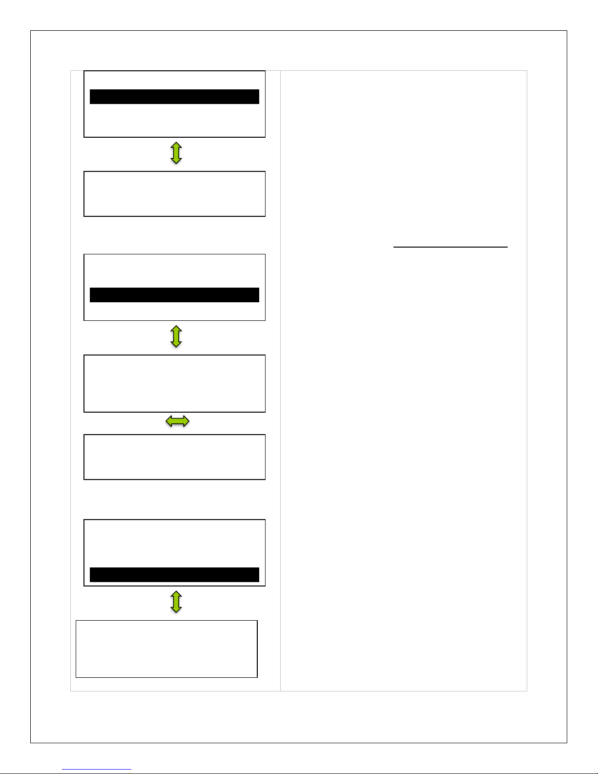
Manual control gives the user complete control
over the load terminals. The user can set it to be
manual by default or not.
NOTE: If ON, load will remain on assuming battery
capacity is enough and no abnormal conditions
occur. Load can be turned off and on by pressing
the OK button on the meter
Equalize Time
120min
Boost Time
120min
Battery Charge SOC
100%
Battery Discharge SOC
30%
Manual Control
Default: ON
√ Manual Control
0Light on/Off
0Light on+Timer
0Timer Control
Page 12
12
ESC
ESC
In Light On/Off the user sets to load to be operated
by the time of day.
The load terminal automatically turns ON when the
solar voltage goes BELOW the point of NTTV
(Night Time Threshold Voltage).The load
automatically turns OFF when the voltage goes
ABOVE the point of DTTV (Day Time Threshold
Voltage). There is a delay between turning the
load on or off and can be programmed to be from
0-99minutes.
NOTE: Minimum and maximum charge parameter
values can be found in Technical Specifications
Similar to Light On/Off parameter with the addition
of a timer that the user sets in order to indicate how
long a load will be on or off. The user also sets an
appropriate time for when it is night time.
Nightime12 indicates the remaining time between
the Load being on and off
NOTE: Timer needs to be activated for it to work
Using a 24-hour clock, the user is able to set the
time for when the load will turn on and the time for
when the load will turn off. The system works fine
with just one timer, the second timer serves the
purpose of dual functioning. For example, if the
user wants to turn the load on and off within 3
hours of night time and turn the load on and off
again before sunrise they will be able to with a dual
timer.
Time Control
Time1/Time2
OnTime 19:00:00
OffTime 06:00:00
0Manual Control
0Light on/Off
0Light on+Timer
√Timer Control
Light On+Timer
OnTime1 01H:00M
OnTime2 01H:00M
Light On+Timer
On 05.0 V Delay 10M
Off 06.0 V Delay 10M
Nightime12 H00
0Manual Control
0Light on/Off
√Light on+Timer
0Timer Control
Light On/Off
On 05.0 V Delay 10M
Off 06.0 V Delay 10M
0Manual Control
√Light on/Off
0Light on+Timer
0Timer Control
Page 13
13
6. Device Parameters
NOTE: Use the up and down arrows to maneuver through the monitoring menus. The left and
right arrows indicate submenus and display further information regarding the system
NOTE: Press OK to change from reading mode to parameter setting mode. Once the parameter
is highlighted, use the UP and DOWN arrows to adjust the setting and press OK once again to
save the setting.
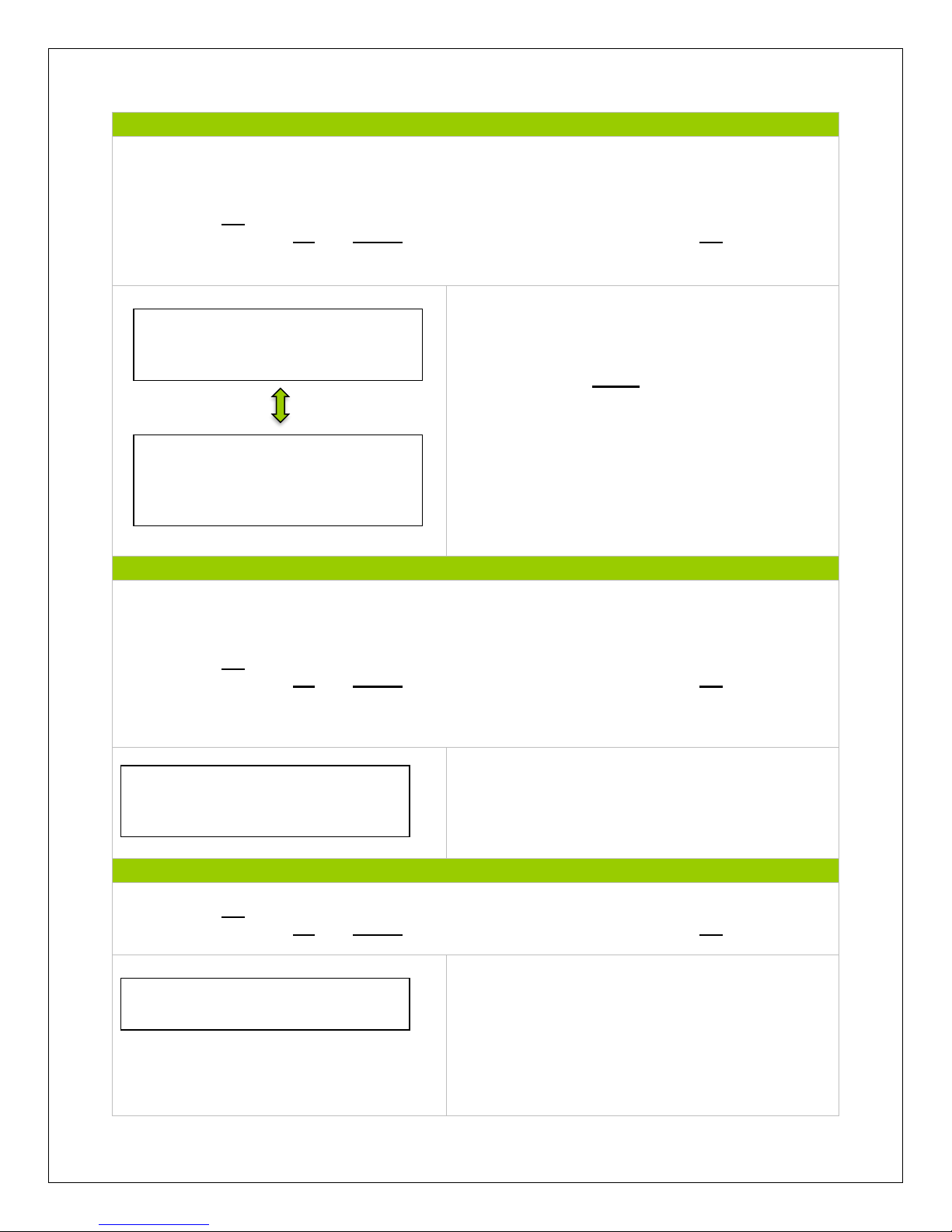
The display will be the version number of the
Charge Controller as well as display the ID. The
ID is important if there are custom settings (For
Example, the USER function), then the
parameters will be saved under that certain ID.
This serves the purpose of having the tracer work
for various charge controllers and their respective
ID’s.
NOTE: The ID of the charge controller and the tracer
must match for them to be operable together.
The backlight is also modifiable as well as the date and
time.
7. Device Password
NOTE: In some models, you might be prompted to enter a password. Simply put “0” all the way
through and press enter.
NOTE: Press OK to change from reading mode to parameter setting mode. Once the parameter
is highlighted, use the UP and DOWN arrows to adjust the setting and press OK once again to
save the setting.
Before making any parameter changes, the user
can have the charge controller require a
password.
8. Factory Reset
NOTE: Press OK to change from reading mode to parameter setting mode. Once the parameter
is highlighted, use the UP and DOWN arrows to adjust the setting and press OK once again to
save the setting.
Reset the controller to factory settings. This will
erase any customized parameters the user may
have set. The default “0” password may also be
activated.
Device Parameter
Backlight 60S
Month-Date-Year
HH:MM:SS
Device Parameter
Ver: Version #
ID: 001
Device Password
OriPsw: XXXXXX
NewPsw: XXXXXX
Factory Reset
YES NO
Page 14
14
9. Failure Info
NOTE: Press OK to change from reading mode to parameter setting mode. Once the parameter
is highlighted, use the UP and DOWN arrows to adjust the setting and press OK once again to
save the setting.
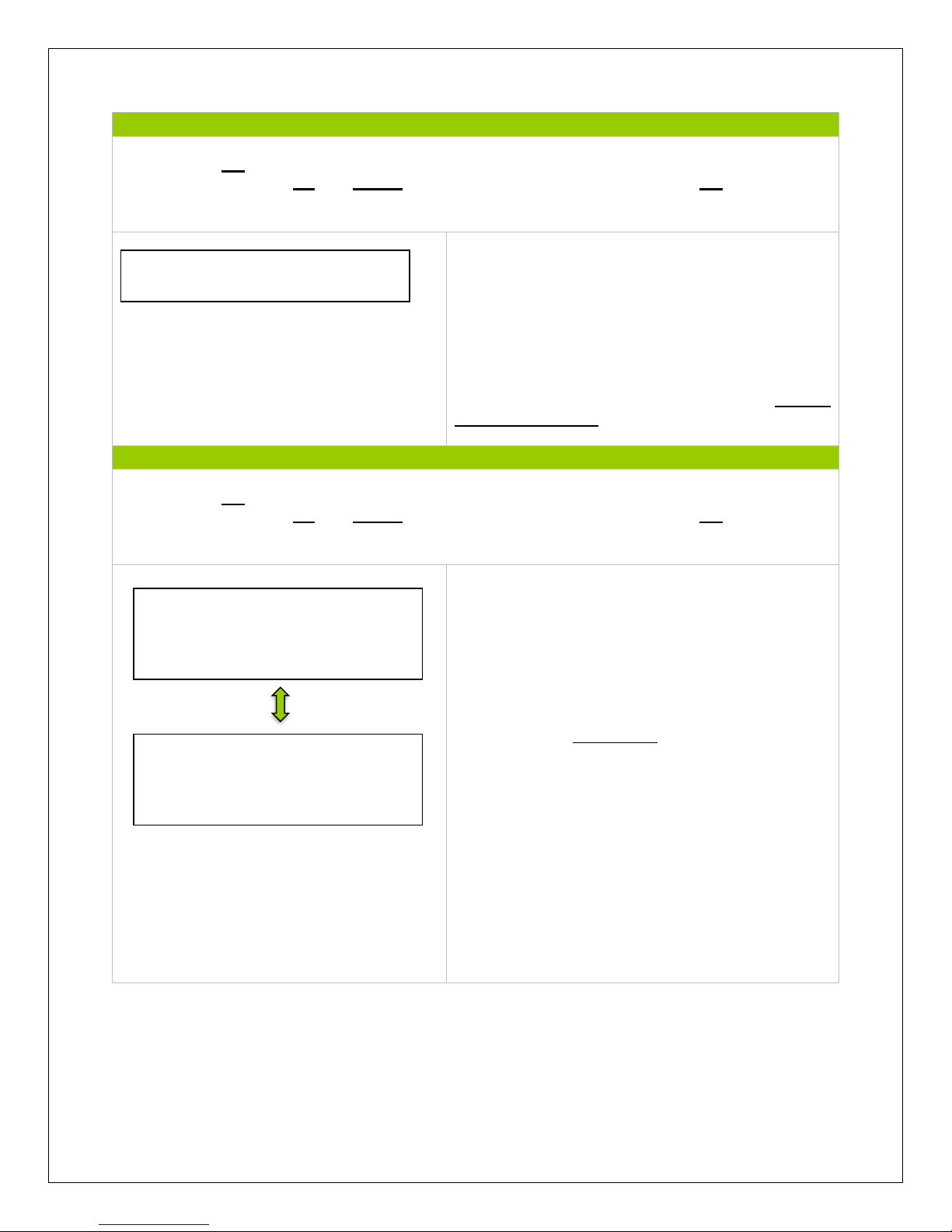
Any faults or indicators that the controller
experiences will be readily available to view in the
Tracer’s Failure information.
A maximum of 15 failure messages could be
displayed. When the failure has been corrected, it
will disappear from the failure information log. For
a list of common failures, check the Failure
Information Table
10. Meter Parameters
NOTE: Press OK to change from reading mode to parameter setting mode. Once the parameter
is highlighted, use the UP and DOWN arrows to adjust the setting and press OK once again to
save the setting.
First screen displays information regarding the
controller and the tracer type.
The Switch-Pages feature allows the menu
screens, under Monitoring, to cycle through the
displays at every second desired by the user.
NOTE: There is a 10 minute delay when modifying
the switch pages feature.
The backlight controls the time it is on, following
the last button being pressed.
The alarm sound can be turned on or off to
indicate error.
NOTE: This alarm feature will be discontinued in
future models.
Failure Info.
Meter Parameters
SW-Pages: 000S
Backlight: 000S
AudAlarm ON
Meter Parameters
Type: MT-50
Version: version #
SN: SN #
Page 15
15
System Status Icons
PV
BATTERY
SYSTEM
LOAD
Day/ PV
Charging
Battery
Charging
System
Normal
Load
ON
Night/ PV
Not
Charging
Battery
Level Full
System
Under
Voltage
Load
OFF
Battery
Over
Discharge
System
Over
Discharged
System Status Glossary
PV Status
Meaning
Connect
PV is Connected
Disconnect
PV is Disconnected
Measure Err
Measurement Error at the PV terminal
Input O. cur.
PV is Overcurrent
RPP Short
(Metal oxide semiconductor) used for PV reverse
polarity is short.
MOS-C Short
(Metal oxide semiconductor) used for charging is
short.
RPP Break
(Metal oxide semiconductor) in control circuit is
damaged
Page 16
16
BATT Status
Meaning
Equalize
Battery is equalizing
Boost
Battery is in boost mode
Float
Battery is in float mode
NoCharge
No charge to battery
LVD
Low voltage disconnect
UVW
Under voltage warning
Normal
Battery is normal
OVD
Over voltage disconnect
Disc.O.O.Ctrl.
Battery experiencing error charging/discharging
Ctrler O.Temp.
Battery is too hot, over temperature
LOAD Status
Meaning
On
Load On
Off
Load Off
Load O. cur.
Load is overloaded
Load Circuit
Load connection is short
Error
Load experiencing error
MOS Short
Metal oxide semiconductor used in load is short
Failure Information
Indicator
Troubleshoot
Load MOS-Short
Reset the controller to factory settings. If problem persists,
contact supplier.
Load Circuit
Load circuit is short. Check the device wiring and connections
going into the load. There may be a break in the wire.
Load O. cur.
Load is overcurrent. Check to make sure the devices connected
to the load terminal are within the load specification. If so, then
reduce the number of loads and it will reconnect automatically.
Input O. cur.
PV terminal overcurrent. Use a multi-meter to determine whether
solar panel(s) specification match the nominal parameters of the
charge controller.
RPP Short
Check connections to make sure they are not reverse. Reset the
controller to factory settings. If problem persists, contact the
supplier
RPP Break
Reset the controller to factory settings. If problem persists,
contact the supplier
Char.MOS-Short
The charge driver is short. Reset the controller to factory
settings. If problem persists, contact the supplier
Page 17
17
Disc.O.O.Ctrl.
Check that the battery connections are properly connected to the
battery terminals of the charge controller. Make sure there is no
short along the line. Reboot the controller. If problem continues,
reset the controller.
Ctrler O.Temp.
Controller Over temperature. Place the controller in a cooler
environment where it will automatically reconnect.
Comm. Timeout
Error with the communication port. Check controller connection
and reboot device.
Device Considerations
Warning Indicator
The red LED on the tracer will turn on where there is an issue. Check the Failure
Information Log first. The following are possible reasons for the warning indicator
1. One battery could be disconnected, over voltage, or open circuit. Check
connections. Disconnect and reconnect.
2. The remote temperature sensor probe is malfunctioning. Check the sensor probe.
Disconnect and reconnect.
3. The system is experiencing overcharging current. Check connections, disconnect
and reconnect
4. Solar PV is short circuited. Check connections, disconnect and reconnect.
Telecommunication Port
When the meter running on individual power or the communication is cut off, the MT-50 will
display graphical symbols abnormally. Press any key to stop the display and resume normal
activity. If problem persists, disconnect the port and connect it again. Normal behavior is when
the meter updates every 20 seconds.
NOTE: Errors could occur in the telecommunication port if the connection is not properly
secured. Also, too long of a cable may cause some inconsistencies.
Battery Level Flashing
The meter measures battery capacity by the voltage it is experiencing. When batteries are
charging, they will not necessarily match the accurate battery capacity.
Battery capacity AH
AH is the accumulation of charging, each one minute will count. The data is not accurate while
the charge current is too small. The min. is 1AH, means 1 amps charging for 1 hour, Ah comes
to show.
Page 18
18
Troubleshooting
MT-50 has no display
• Verify the charge controller is powered on and that it is securely connected to the MT-50.
LCD display is dim
• Check the system battery voltage. The MT-50 needs a minimum of 8 V to operate.
• Verify that the temperature is within range of the LCD operating parameters.
MT-50 turns on, but shows no data
• MT-50 is potentially damaged or the cable is damaged. Replace the cable by contacting
the manufacturer.
MT-50 display does not match product manual
• Our products undergo manual revisions from time to time. Please check our website at
Renogy-store.com > downloads for latest documentation.
Buttons do not work
• Disconnect the MT-50 and clean the faceplate to remove any potential buildup of residue
• Reconnect MT-50
Technical Specifications
Mechanical Parameters
Communication Cable
RJ45 (8 pin)
Cable Length
2 m (6.5 ft)
Faceplate Dimensions
98 x 98mm (3.86 x 3.86in)
Wall Frame Dimensions
114 x 114mm (4.49 x 4.49in)
Weight
0.23 Kg
Temperature Parameters
Operation Temperature
-4°F to 158°F
Humidity
0-100%
Electrical Parameters
Rated Voltage
12V
Minimum Voltage Suggested
8V
Strong backlight on consumption
< 23mA
Backlight and LED indicator off
consumption
< 15mA
Page 19
19
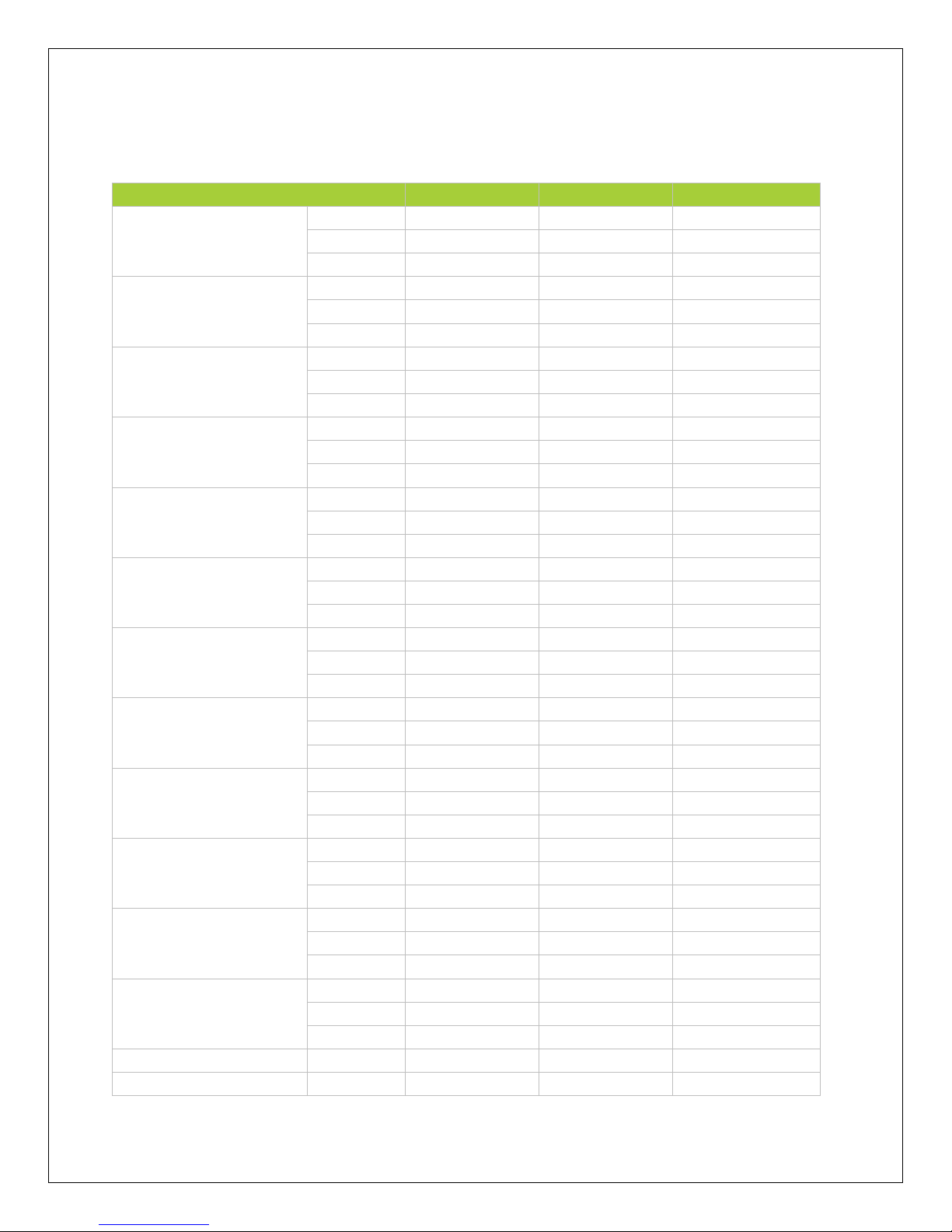
Charging Parameters
Battery type
Gel
Sealed
Flooded
High Volt Disconnect
Default
16.0V; x2/24V
16.0V; x2/24V
16.0V; x2/24V
Max
17.0V; x2/24V
17.0V; x2/24V
17.0V; x2/24V
Min
15.0V; x2/24V
15.0V; x2/24V
15.0V; x2/24V
Charging Limit Voltage
Default
15.5V; x2/24V
15.5V; x2/24V
15.5V; x2/24V
Max
16.0V; x2/24V
16.0V; x2/24V
16.0V; x2/24V
Min
14.0V; x2/24V
14.0V; x2/24V
14.0V; x2/24V
Over Voltage
Reconnect
Default
15.0V; x2/24V
15.0V; x2/24V
15.0V; x2/24V
Max
16.0V; x2/24V
16.0V; x2/24V
16.0V; x2/24V
Min
14.0V; x2/24V
14.0V; x2/24V
14.0V; x2/24V
Equalization Voltage
Default
N/A
14.6V; x2/24V
14.8V; x2/24V
Max
N/A
15.2V; x2/24V
15.2V; x2/24V
Min
N/A
14.2V; x2/24V
14.2V; x2/24V
Boost Voltage
Default
14.2V; x2/24V
14.4V; x2/24V
14.6V; x2/24V
Max
15V; x2/24V
15V; x2/24V
15V; x2/24V
Min
13.8V; x2/24V
13.8V; x2/24V
13.8V; x2/24V
Float Voltage
Default
13.8V; x2/24V
13.8V; x2/24V
13.8V; x2/24V
Max
14.2V; x2/24V
14.2V; x2/24V
14.2V; x2/24V
Min
13.2V; x2/24V
13.2V; x2/24V
13.2V; x2/24V
Boost Return Voltage
Default
13.2V; x2/24V
13.2V; x2/24V
13.2V; x2/24V
Max
13.5V; x2/24V
13.5V; x2/24V
13.5V; x2/24V
Min
12.7V; x2/24V
12.7V; x2/24V
12.7V; x2/24V
Low Voltage
Reconnect
Default
13.2V; x2/24V
13.2V; x2/24V
13.2V; x2/24V
Max
13.5V; x2/24V
13.5V; x2/24V
13.5V; x2/24V
Min
12.7V; x2/24V
12.7V; x2/24V
12.7V; x2/24V
Under Voltage Recover
Default
12.2V; x2/24V
12.2V; x2/24V
12.2V; x2/24V
Max
12.6V; x2/24V
12.6V; x2/24V
12.6V; x2/24V
Min
11.8V; x2/24V
11.8V; x2/24V
11.8V; x2/24V
Under Voltage Warning
Default
12.0V; x2/24V
12.0V; x2/24V
12.0V; x2/24V
Max
12.4V; x2/24V
12.4V; x2/24V
12.4V; x2/24V
Min
11.6V; x2/24V
11.6V; x2/24V
11.6V; x2/24V
Low Voltage
Disconnect
Default
11.1V; x2/24V
11.1V; x2/24V
11.1V; x2/24V
Max
11.8V; x2/24V
11.8V; x2/24V
11.8V; x2/24V
Min
10.5V; x2/24V
10.5V; x2/24V
10.5V; x2/24V
Discharging Limit
Voltage
Default
10.8V; x2/24V
10.8V; x2/24V
10.8V; x2/24V
Max
11V; x2/24V
11V; x2/24V
11V; x2/24V
Min
10.5V; x2/24V
10.5V; x2/24V
10.5V; x2/24V
Equalize Duration
N/A
N/A
2 hours
2 hours
Boost Duration
N/A
2 hours
2 hours
2 hours
Page 20
20
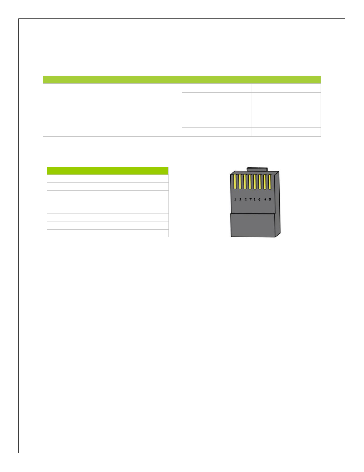
Threshold Voltage Parameters
The following chart demonstrates the parameters when using the Timer under load settings.
Description
Parameter
Day Time Threshold Voltage (DTTV)
Default
5V; x2/24V
Max
10V; x2/24V
Min
1V; x2/24V
Night Time Threshold Voltage (NTTV)
Default
6V; x2/24V
Max
10V; x2/24V
Min
1V; x2/24V
Interface Pin Numbers
Pin Number
Definition
1
Power +5 to 12V input
2
Power +5 to 12V input
3
RS485-B
4
RS485-B
5
RS485-A
6
RS485-A
7
GND
8
GND
Page 21
21
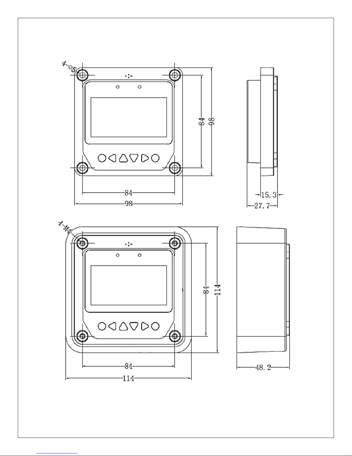
CAD Dimensions
NOTE: Dimensions are in millimeters
 Loading...