

Page 1
0
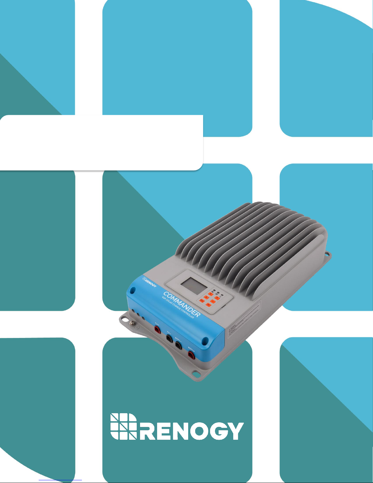
Commander Series
RENOGY 60A
Maximum Power Point Tracking Solar Charge Controller
2775 E. Philadelphia St., Ontario, CA 91761
1-800-330-8678
Version 3.0
Page 2

1
Important Safety Instructions
Please save these instructions.
This manual contains important safety, installation, and operating instructions for the
charge controller. The following symbols are used throughout the manual to indicate
potentially dangerous conditions or important safety information.
WARNING: Indicates a potentially dangerous condition. Use extreme caution when
performing this task.
CAUTION: Indicates a critical procedure for safe and proper operation of the controller
NOTE: Indicates a procedure or function that is important to the safe and proper operation
of the controller.
General Safety Information
• Read all of the instructions and cautions in the manual before beginning the
installation.
• There are no serviceable parts for this controller. Do NOT disassemble or attempt
to repair the controller.
• Do NOT allow water to enter the controller.
• Make sure all connections going into and from the controller are tight.
Charge Controller Safety
• NEVER connect the solar panel array to the controller without a battery. Battery
must be connected first.
• Ensure input voltage does not exceed 150 VDC to prevent permanent damage.
Use the Open Circuit (Voc) to make sure the voltage does not exceed this value
when connecting panels together.
• Do not exceed 60A for the charge controller The Short Circuit (Isc) of the solar array
should be less than 60A.
Page 3
2
Battery Safety
• Use only sealed lead-acid, flooded, or gel batteries which must be deep cycle.
• Explosive battery gases may be present while charging. Be certain there is enough
ventilation to release the gases.
• Be careful when working with large lead acid batteries. Wear eye protection and
have fresh water available in case there is contact with the battery acid.
• Carefully read battery manuals before operation.
• Do NOT let the positive (+) and negative (-) terminals of the battery touch each
other.
• Recycle battery when it is replaced.
• Over-charging and excessive gas precipitation may damage the battery plates and
activate material shedding on them. Too high of an equalizing charge or too long
of one may cause damage. Please carefully review the specific requirements of
the battery used in the system.
• Equalization is carried out only for non-sealed / vented/ flooded / wet cell lead acid
batteries.
• Do NOT equalize VRLA type AGM / Gel cell batteries UNLESS permitted by
battery manufacturer.
WARNING: Connect battery terminals to the charge controller BEFORE connecting
the solar panel(s) to the charge controller. NEVER connect solar panels to charge
controller until the battery is connected.
WARNING: Do NOT connect any inverters or battery charger into the load terminal
of the charge controller.
WARNING: Once equalization is active in the battery charging, it will not exit this
stage unless there is adequate charging current from the solar panel. There should
be NO load on the batteries when in equalization charging stage.
Page 4

3
Table of Contents
General Information .................................................................................................................................... 4
Additional Components .............................................................................................................................. 8
Optional Components ................................................................................................................................. 8
Identification of Parts ................................................................................................................................. 9
PV Array Requirements ............................................................................................................................ 10
PV Strings .............................................................................................................................................. 10
PV Max Power ....................................................................................................................................... 10
Installation ................................................................................................................................................. 11
Operation ................................................................................................................................................... 16
1. Monitoring ......................................................................................................................................... 17
2. Log Info .............................................................................................................................................. 18
3. Clock Set ............................................................................................................................................ 19
4. Local Para Set ................................................................................................................................... 19
5. Control Para Set ................................................................................................................................ 20
6. Sys Password ................................................................................................................................... 22
7. Default Set ......................................................................................................................................... 22
8. Dev Msg ............................................................................................................................................. 22
System Status Icons ................................................................................................................................. 23
LED Indicators ........................................................................................................................................... 23
Commander Protections .......................................................................................................................... 24
System Status Troubleshooting .............................................................................................................. 25
Maintenance .............................................................................................................................................. 26
Fusing ......................................................................................................................................................... 26
Technical Specifications .......................................................................................................................... 27
Electrical Parameters ........................................................................................................................... 27
Charging Parameters ........................................................................................................................... 28
Charging Parameters Glossary ........................................................................................................... 28
Mechanical Parameters ........................................................................................................................ 30
Environment Parameters ..................................................................................................................... 30
Conversion Efficiency Curves ............................................................................................................. 31
PC Software ............................................................................................................................................... 33
Dimensions ................................................................................................................................................ 36
Page 5

4
General Information
The RENOGY Commander MPPT controller is suitable for off-grid solar applications. It
protects the battery from being over-charged by the solar modules and over-discharged
by the loads. The controller features a smart tracking algorithm that maximizes the energy
from the solar PV module(s) and charge the battery.
The MPPT Charge Controller charging process has been optimized for long battery life
and improved system performance. The comprehensive self-diagnostics and electronic
protection functions can prevent damage from installation mistakes or system faults. In
addition, the controller is a high-end industrial class product based on multiphase
synchronous rectification technology and has features of high efficiency and reliability.
Key Features
• LCD display with 6 button combination for easy operation.
• 12V / 24V / 36V / 48V DC systems.
• Advanced maximum power point tracking technology with the tracking efficiency
as high as 99.5%
• Multiphase synchronous rectification technology ensuring peak conversion
efficiency up to 98%
• Excellent heat dissipation with integration of the cast aluminum radiator shell. The
controller can be natural cooling.
• Unique dual timer function; enhance the flexibility lighting systems.
• Deep cycle Sealed, Gel, Flooded or User battery option.
• Adopting temperature compensation and correcting the charging and discharging
parameters automatically, improving battery lifetime.
• Electronic protection: Overcharging, over-discharging, overload, and short circuit.
• Protection against over-temperature, over-charging, PV short, reverse polarity,
and over current.
• RS-232, RS-485, and CAN port compatible for extra features.
• Remote Temperature Sensor adaptable and Battery Voltage Sensor adaptable
MPPT Technology
The Commander MPPT Charge Controller utilizes Maximum Power Point Tracking
technology to extract maximum power from the solar module(s). The tracking algorithm
is fully automatic and does not require user adjustment. MPPT technology will track the
array’s maximum power point voltage (Vmp) as it varies with weather conditions, ensuring
that the maximum power is harvested from the array throughout the course of the day.
Current Boost
In many cases, the Commander MPPT charge controller will “boost” up the current
in the solar system. The current does not come out of thin air. Instead, the power
Page 6
5
generated in the solar panels is the same power that is transmitted into the battery bank.
Power is the product of Voltage (V) x Amperage (A). Therefore, assuming 100%
efficiency:
Power In = Power Out
Volts In * Amps In = Volts out * Amps out
Although MPPT controllers are not 100% efficient, they are very close at about 92-95%
efficient. Therefore, when the user has a solar system whose Vmp is greater than the
battery bank voltage, then that potential difference is proportional to the current boost.
The voltage generated at the solar module needs to be stepped down to a rate that could
charge the battery in a stable fashion by which the amperage is boosted accordingly to
the drop. It is entirely possible to have a solar module generate 8 amps going into the
charge controller and likewise have the charge controller send 10 amps to the battery
bank. This is the essence of the MPPT charge controllers and their advantage over
traditional charge controllers. In traditional charge controllers, that stepped down voltage
amount is wasted because the controller algorithm can only dissipate it as heat. The
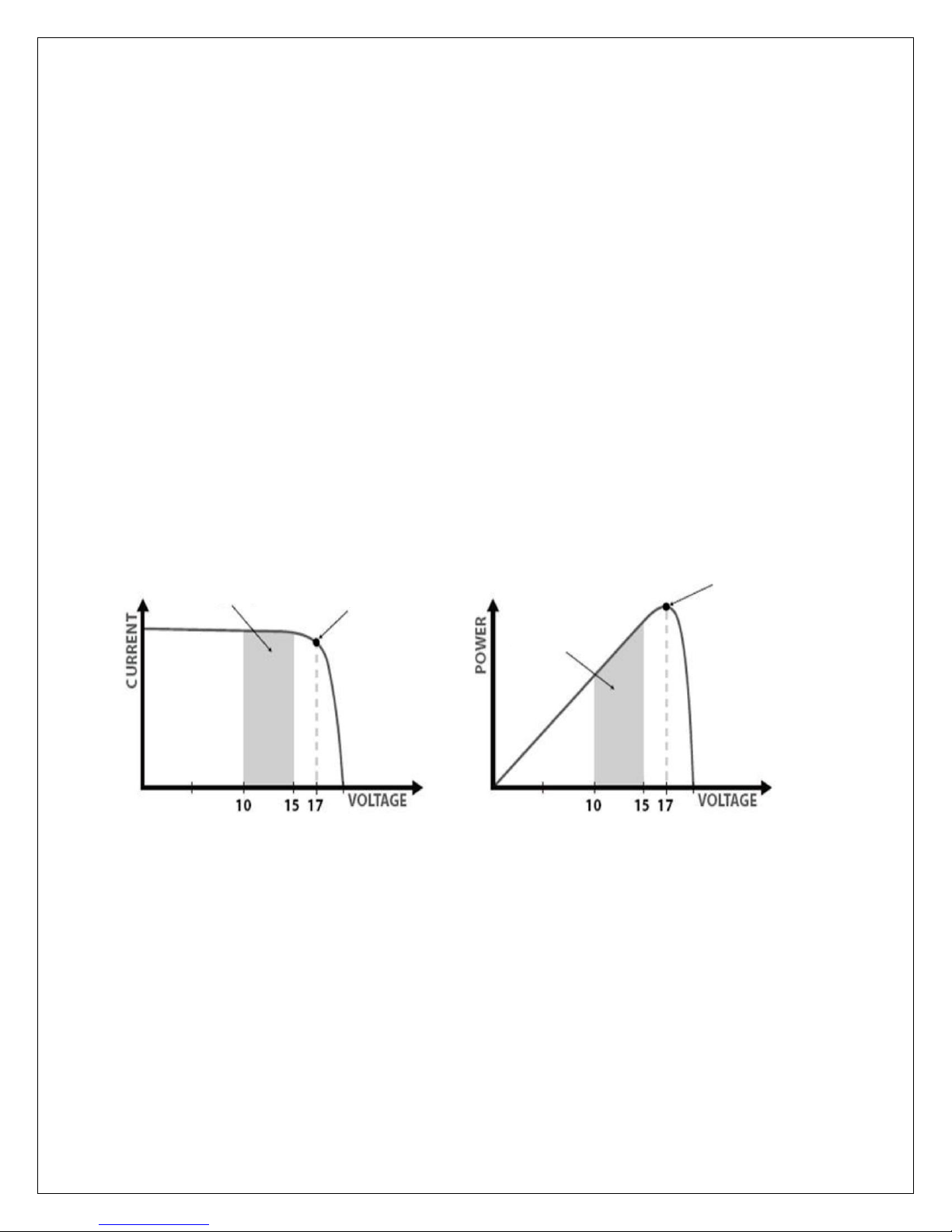
following demonstrates a graphical point regarding the output of MPPT technology.
Limiting Effectiveness
Temperature is a huge enemy of solar modules. As the environmental temperature
increases, the operating voltage (Vmp) is reduced and limits the power generation of the
solar module. Despite the effectiveness of MPPT technology, the charging algorithm will
possibly not have much to work with and therefore there is an inevitable decrease in
performance. In this scenario, it would be preferred to have modules with higher nominal
voltage, so that despite the drop in performance of the panel, the battery is still receiving
a current boost because of the proportional drop in module voltage.
Typical Battery
Voltage Range
Maximum
Power Point
Traditional
Controller
Operating
Range
Maximum
Power Point
Current vs. Voltage (12V System)
Output Power (12V System)
Page 7
6
Four Charging Stages
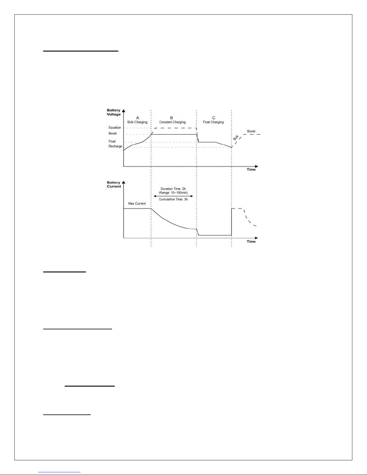
The Commander MPPT charge controller has a 4-stage battery charging algorithm for a
rapid, efficient, and safe battery charging. They include: Bulk Charge, Boost Charge, Float
Charge, and Equalization*.
Bulk Charge: This algorithm is used for day to day charging. It uses 100% of available
solar power to recharge the battery and is equivalent to constant current. In this stage the
battery voltage has not yet reached constant voltage (Equalize or Boost), the controller
operates in constant current mode, delivering its maximum current to the batteries (MPPT
Charging)
Constant Charging: When the battery reaches the constant voltage set point, the
controller will start to operate in constant charging mode, where it is no longer MPPT
charging. The current will drop gradually. This has two stages, equalize and boost and
they are not carried out constantly in a full charge process to avoid too much gas
precipitation or overheating of the battery.
➢ Boost Charge: Boost stage maintains a charge for 2 hours by default. The user
can adjust the constant time and preset value of boost per their demand.
Float Charge: After the constant voltage stage, the controller will reduce the battery
voltage to a float voltage set point. Once the battery is fully charged, there will be no more
Page 8
7
chemical reactions and all the charge current would turn into heat or gas. Because of this,
the charge controller will reduce the voltage charge to smaller quantity, while lightly
charging the battery. The purpose for this is to offset the power consumption while
maintaining a full battery storage capacity. In the event that a load drawn from the battery
exceeds the charge current, the controller will no longer be able to maintain the battery
to a Float set point and the controller will end the float charge stage and refer back to bulk
charging.
Equalization: Is carried out every 28 days of the month. It is intentional overcharging
of the battery for a controlled period of time. Certain types of batteries benefit from
periodic equalizing charge, which can stir the electrolyte, balance battery voltage and
complete chemical reaction. Equalizing charge increases the battery voltage, higher than
the standard complement voltage, which gasifies the battery electrolyte.
WARNING: Once equalization is active in the battery charging, it will not exit this
stage unless there is adequate charging current from the solar panel. There should
be NO load on the batteries when in equalization charging stage.
WARNING: Over-charging and excessive gas precipitation may damage the battery
plates and activate material shedding on them. Too high of equalizing charge or for
too long may cause damage. Please carefully review the specific requirements of
the battery used in the system.
WARNING: Equalization may increase battery voltage to a level damaging to
sensitive DC loads. Ensure that all load allowable input voltages are greater than
the equalizing charging set point voltage.
Page 9
8
Additional Components
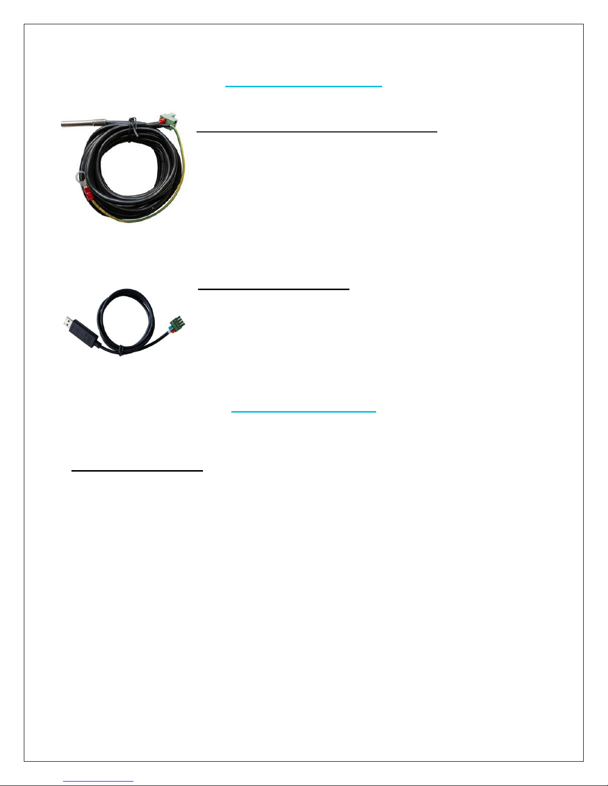
Remote Temperature Sensor (TS-R): Measures the
temperature at the battery and uses this data for very accurate
temperature compensation. It is not polarity sensitive.
USB to RS-485 Converter: The USB to RS-485 converter is
used to monitor each controller on the network using Solar
Station Monitor PC software and update the firmware. It connects
to the RS-485 port on the controller. Download the PC software
through Renogy’s website under the “Downloads” section
Optional Components
Optional components that require a separate purchase:
External Battery (RTC): Allows for the access to the charge controller’s saved settings,
charge accumulation, and discharge accumulation without connecting to a deep cycle
battery. It keeps track of the date/time (once set) for automatic equalization processes.
Page 10
9
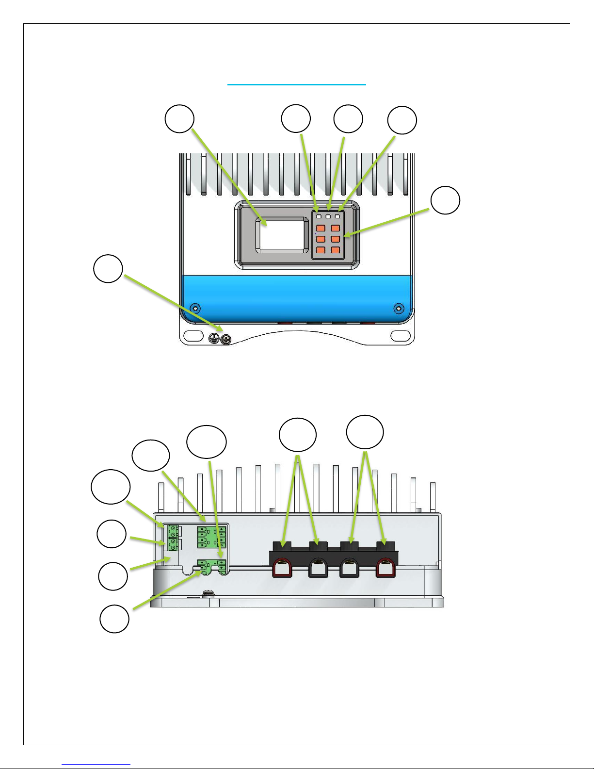
Identification of Parts
2 3 4 5 6
1
10
9
8
7
11
12
13
14
Top View
Front View (Hatch Removed)
Page 11
10
Key Parts
1. Grounding Bolt
2. LCD Display
3. Battery LED
4. PV LED
5. Fault LED
6. Navigation Buttons
7. RS-485 port—monitor controller through PC and update firmware
8. RTC Battery Slot—model is CR2032
9. Remote Temperature Sensor Port—optional accessory to remotely monitor battery
temperature
10. Remote Battery Voltage Sensor Port—Provides accurate battery voltage
measurement
11. Reserved Port—Reserved port for future development. Special accessory currently
not sold.
12. RS-232 port—monitor controller through PC and update firmware
13. PV Terminal
14. Battery Terminal
PV Array Requirements
PV Strings
The commander is suitable for various types of PV configurations to maximize electrical
energy. Configurations are dependent on the open circuit voltage (Voc) and maximum
power point voltage (Vmp) located in solar panel specifications. The following table is to
serve as a reference only.
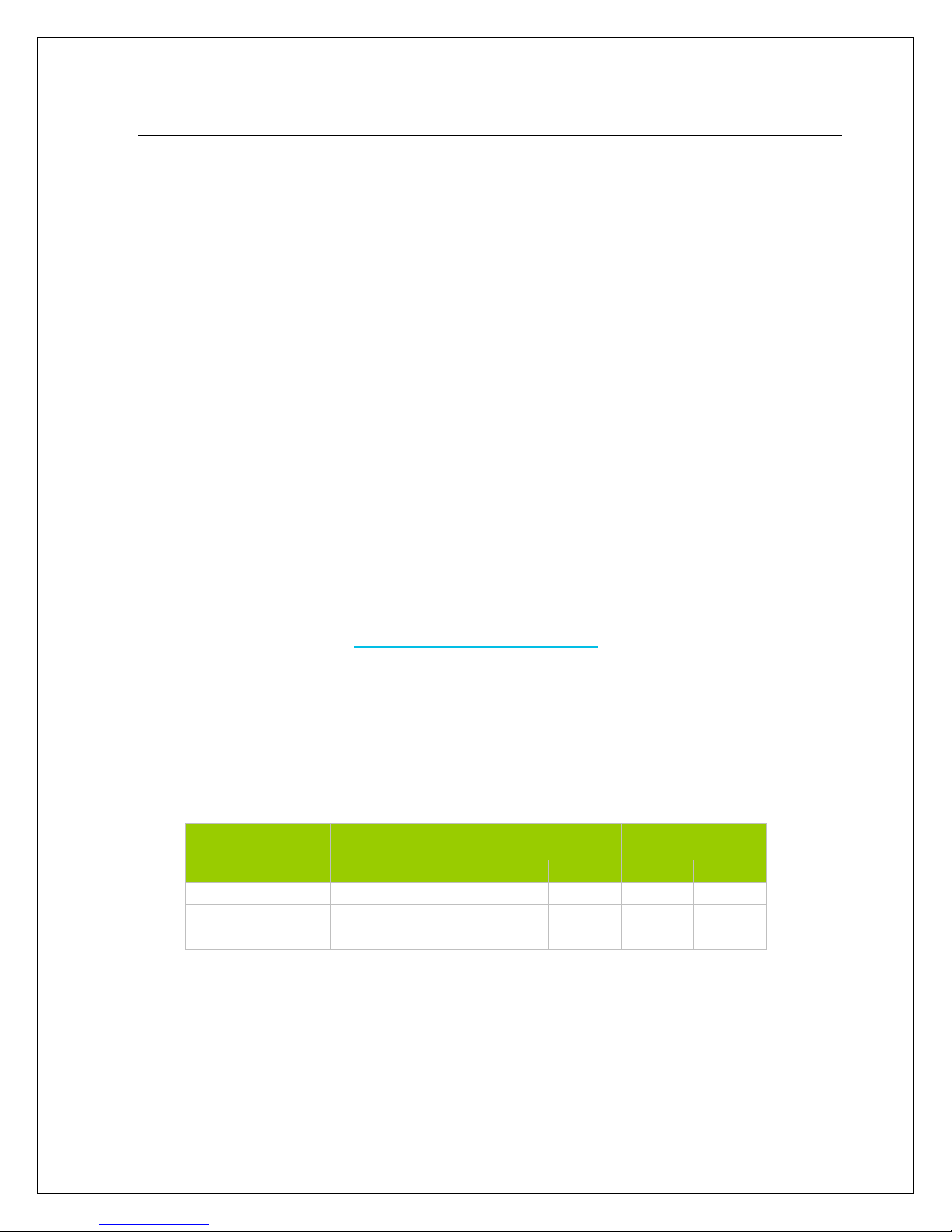
System Voltage
36 Cell Module
(Voc < 23V)
60 Cell Module
(Voc < 38V)
72 Cell Module
(Voc < 46V)
Max
Best
Max
Best
Max
Best
12V
4 2 2 1 2 1 24V
6 3 3 2 3 2 48V
6 5 3 3 3
2
Note: The above parameter values are calculated under the STC conditions: Irradiance 1000W/m2,
Temperature 25°C, Air Mass 1.5
PV Max Power
The Commanders have a limiting current function, where the current is limited within a
range, and therefore allows battery charging at the correct value despite oversized input
power. The power operation follows the following conditions:
Page 12
11
1. PV Actual Power ≤ controller rated charge power, the controller charge battery at
the actual maximum power point.
2. PV Actual Power ≤ controller rated charge power, the controller charges the
battery at the rated power.
WARNING: The Commander will be damaged if the PV array is 3X greater than the
actual operating power of the controller.
WARNING: The Commander’s reverse polarity is no longer warranted if the PV
array size is 1.5X greater than the rated power of the controller.
The following tables serves as the reference guide for the statements above:
Model
Rated Charge
Current
Rated Charge
Power
Max PV Array
Power
Max PV Voc
Input
Commander
60A
800W @ 12V
1600W @ 24V
2400W @ 36V
3200W @ 48V
2400W @ 12V
4800W @ 24V
7200W @ 36V
9600W @ 48V
150V @
minimum
operating
environmental
temperature
OR
138V @ 25°C
environmental
temperature
Installation
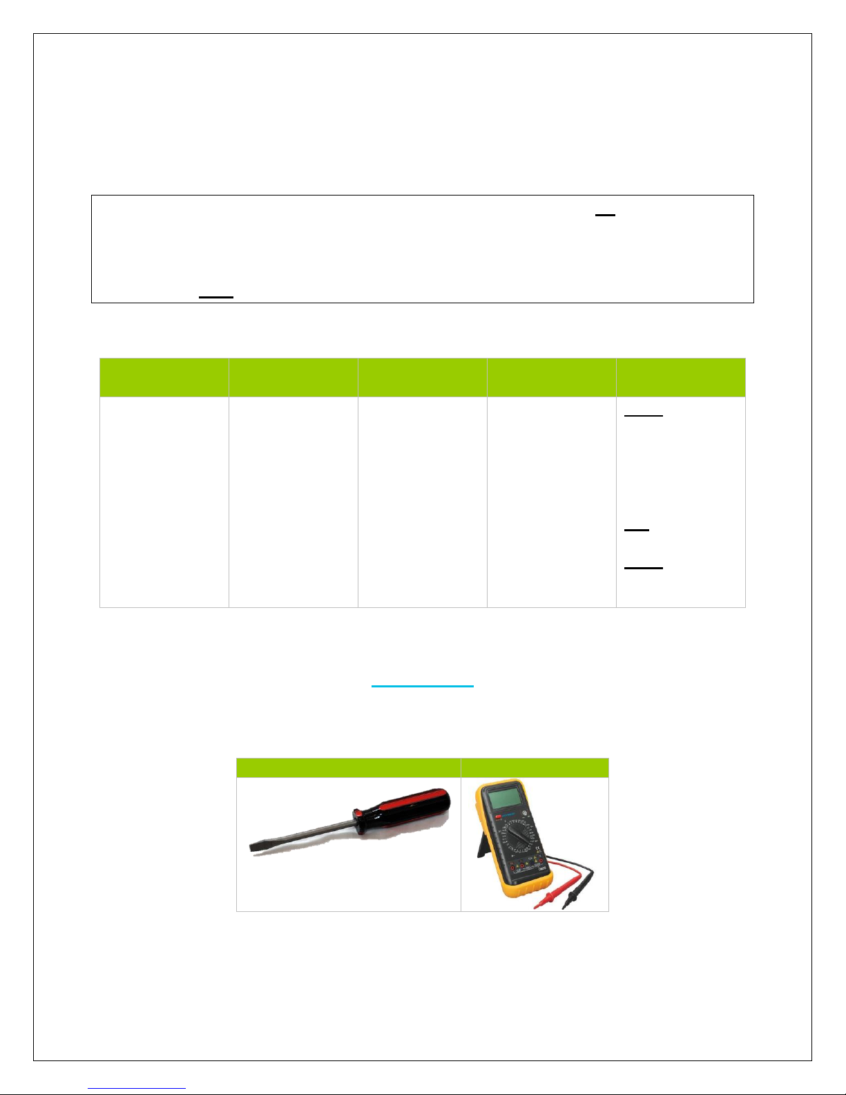
Recommended tools to have before installation:
Flathead Screwdriver
Multi-Meter
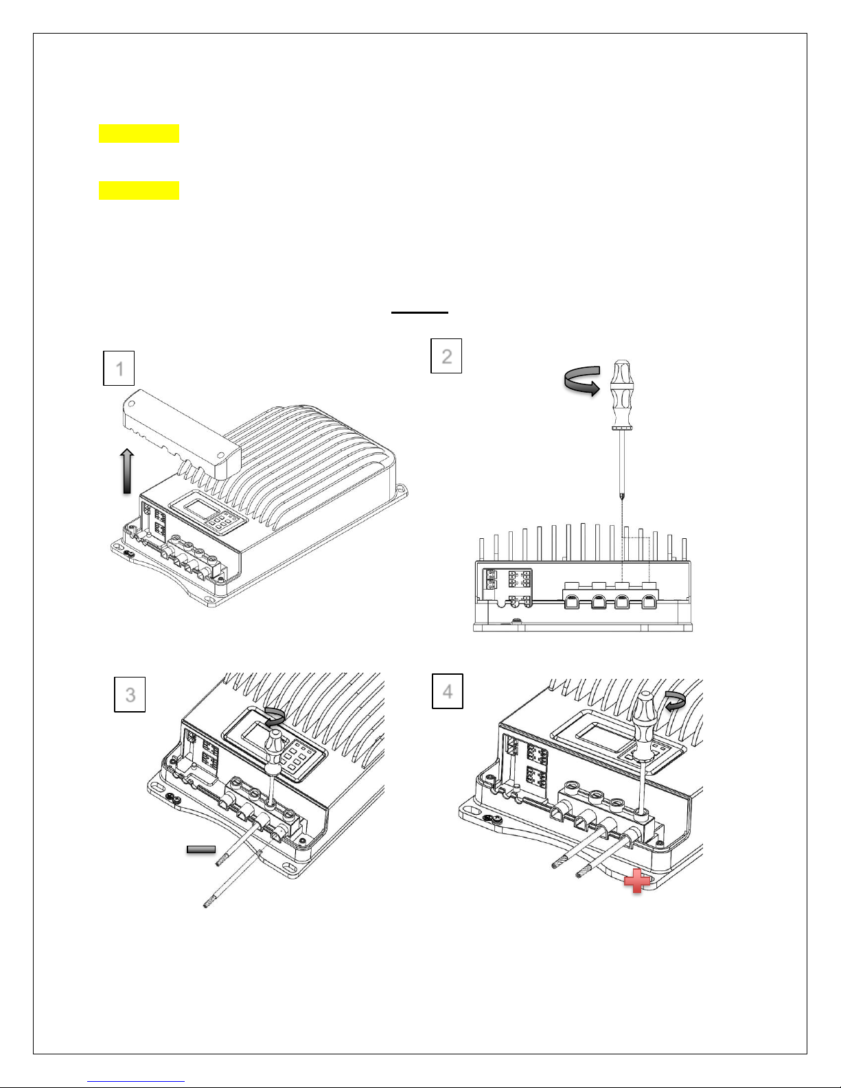
WARNING: Connect battery terminal wires to the charge controller FIRST then
connect the solar panel(s) to the charge controller. NEVER connect solar panel to
charge controller before the battery.
Page 13
12
CAUTION: Do not over-torque or over tighten the screw terminals. This could
potentially break the piece that holds the wire to the charge controller.
CAUTION: Refer to the technical specifications for max wire sizes on the controller
and for the maximum amperage going through wires.
You are now ready to begin connecting your battery to your charge controller.
Battery
1
2
3
4
Page 14
13
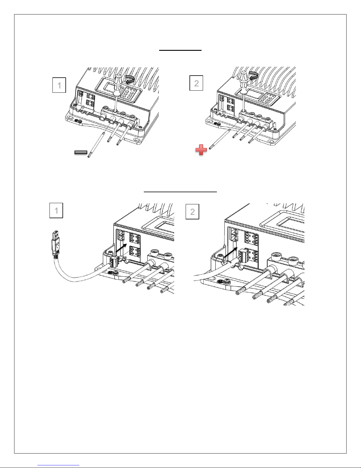
Solar Panels
Computer connection
2 2 1
1
Page 15
14
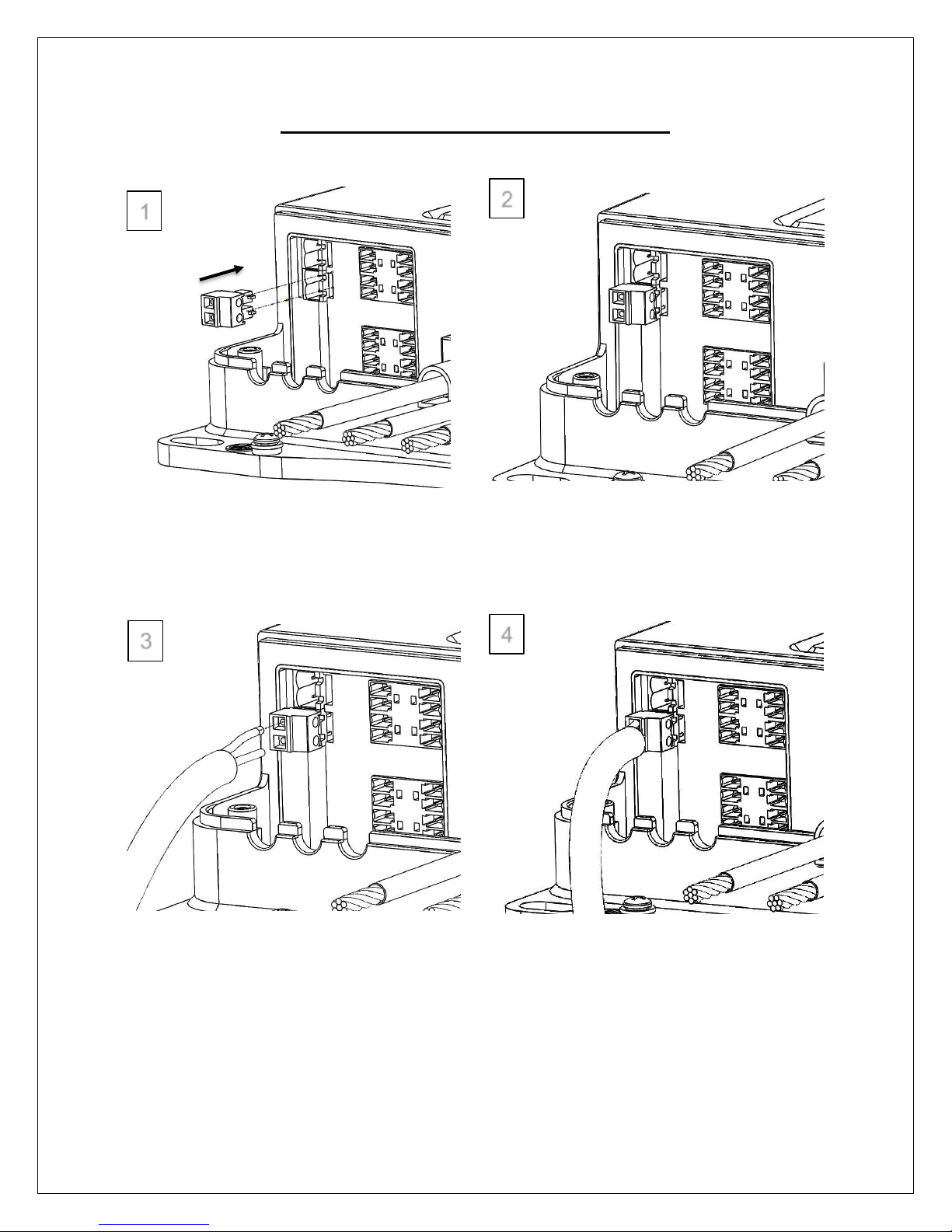
Temperature sensor (Not Polarity Sensitive)
1
2
3
4
Page 16
15
Mounting Recommendations
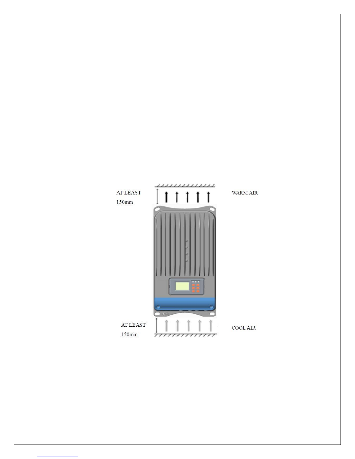
NOTE: The Commander MPPT 60 controller requires at least 6 inches(150mm) of
clearance above and below for proper air flow. Ventilation is highly recommended
if mounted in an enclosure.
WARNING: Never install the controller in a sealed enclosure with flooded batteries.
Gas can accumulate and there is a risk of explosion.
1. Choose Mounting Location—place the controller on a vertical surface protected
from direct sunlight, high temperatures, and water. Make sure there is good
ventilation.
2. Check for Clearance—verify that there is sufficient room to run wires, as well as
clearance above and below the controller for ventilation. The clearance should be
at least 6 inches (150mm).
3. Mark Holes—Mark the four mounting holes locations on the mounting surface.
4. Drill Holes—Remove the controller and drill four sizeable holes at the marked
locations.
5. Secure the charge controller—Place the controller on the surface and align the
mounting holes with the drilled holes in step 4. Secure the controller in place using
the mounting screws.
Page 17
16
Operation
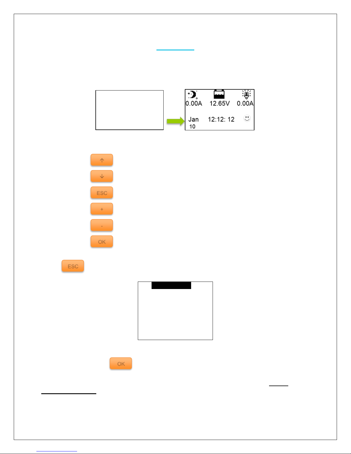
After connecting the battery to the charge controller, the controller will turn on
automatically. The user will be prompted by an initialization screen, followed by the
charge controller’s rated parameters, and finally the default monitoring screen.
Use the following buttons to maneuver through the menu:
Cycle through the menu
Cycle through the menu
Return to main menu in any monitoring interface
Modify any value and set period of Log to browse
Modify any value and set period of Log to browse
Selecting certain parameters
Select to display the menu screen selection. The user will have 9 interfaces to
choose from.
1. Monitoring
2. Log Info
3. Clock Set
4. Local Para Set
5. Control Para
6. Sys Password
7. Default Set
8. Device Msg
NOTE: You might be prompted to enter a password. Simply put “0” all the way
through by pressing
NOTE: To customize charge parameters, BATT TYPE must be set to USER under
5. Control Param
ESC + -
OK
Rated Parameters
Rat.Volt 48.0V
Charg.Cur 60.0A
Disc.Curr 60.0A
ESC
OK
Page 18
17
NOTE: The values found in your controller are default values and will not
necessarily match the ones listed. The values on this table are to show the user
what the different screens are used for.
NOTE: You do NOT have to program the control. These parameters are for extra
features. Once you connect the battery the settings are automatically synced.
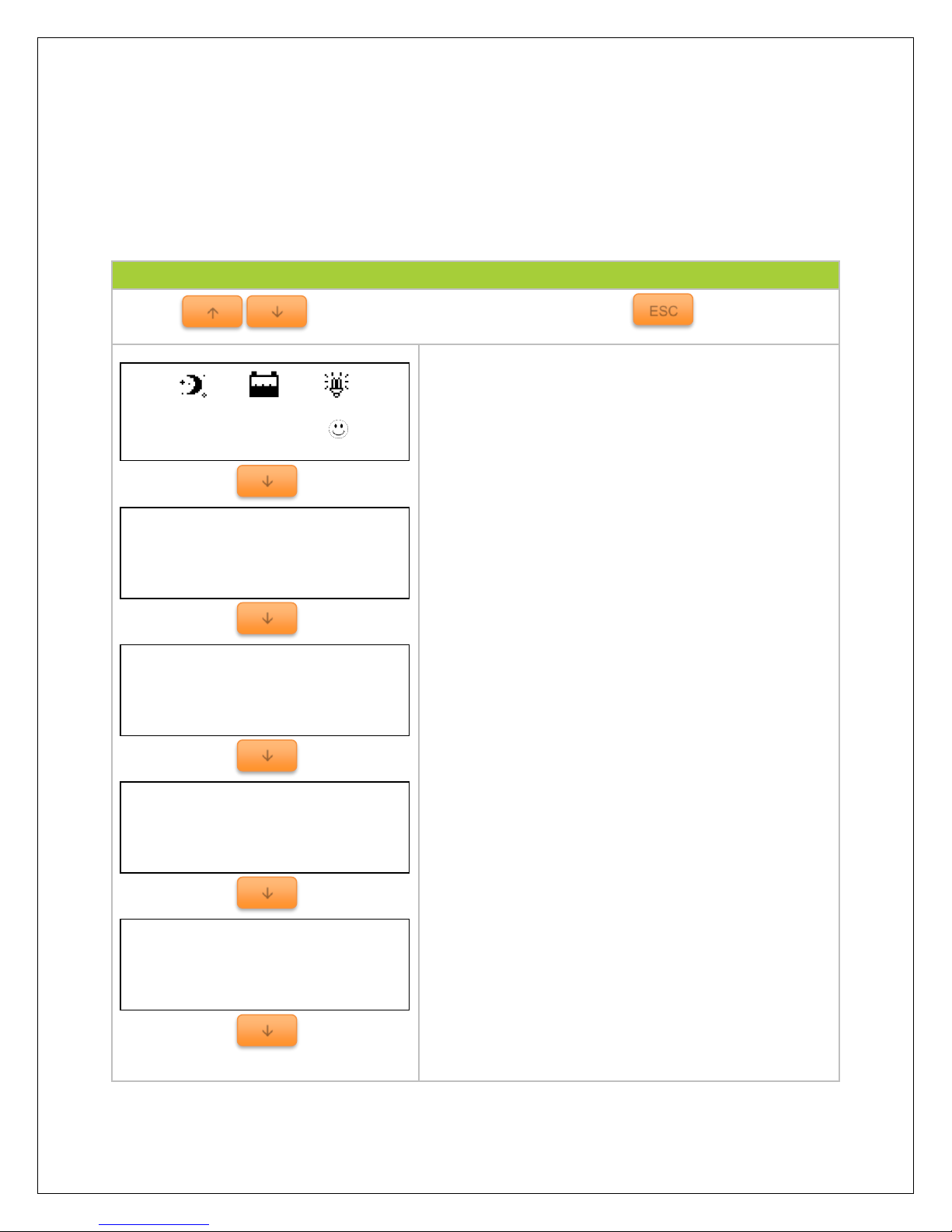
1. Monitoring
Use the keys to maneuver through the screens and to access the
menu
Default monitoring screen displaying charge controller
system status through icons.
Indicates battery voltage and battery current
Indicates the maximum and minimum battery values
since the charge controller has been turned on. When
battery is charging, the values are expected to
change.
Displays the battery state as well as the state of
charge of the battery.
NOTE: The Battery SOC% is an estimation based on
the charging voltage.
Displays the charging state of the battery as well as
the voltage coming from the PV module(s).
NOTE: Make sure PV input is not more than 150 VDC
Charge State
No Charge
PV Volt
0.0 V
Batt State
Normal
Batt SOC
51%
Batt Day’Max
12.8 V
Batt Day’Min
12.6 V
Batt Volt.
12.6 V
Batt Cur.
0.0 A
0.00A 12.65V 0.00A
Jan 12:12: 12
ESC
Page 19
18
Indicates the amount of energy that has been
generated for the day in terms of kilowatt-hours per
day. The PV power indicates how much power the PV
modules have generated.
Indicates the total amount of energy generated and in
kilowatt-hours per day.
Indicates the batteries temperature as well as the
temperature compensation. Temperature fluctuation
can affect performance in the system. The purpose of
temperature compensation is to adjust the
performance of the system to keep the system
functioning normally.
Indicates the local temperature of the charge
controller.
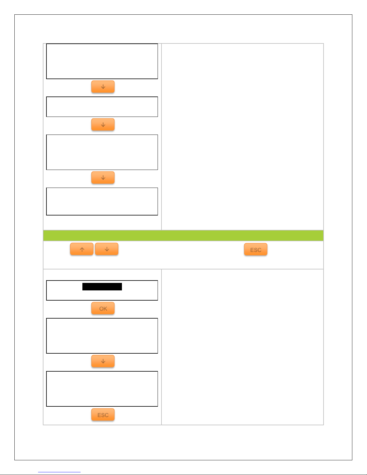
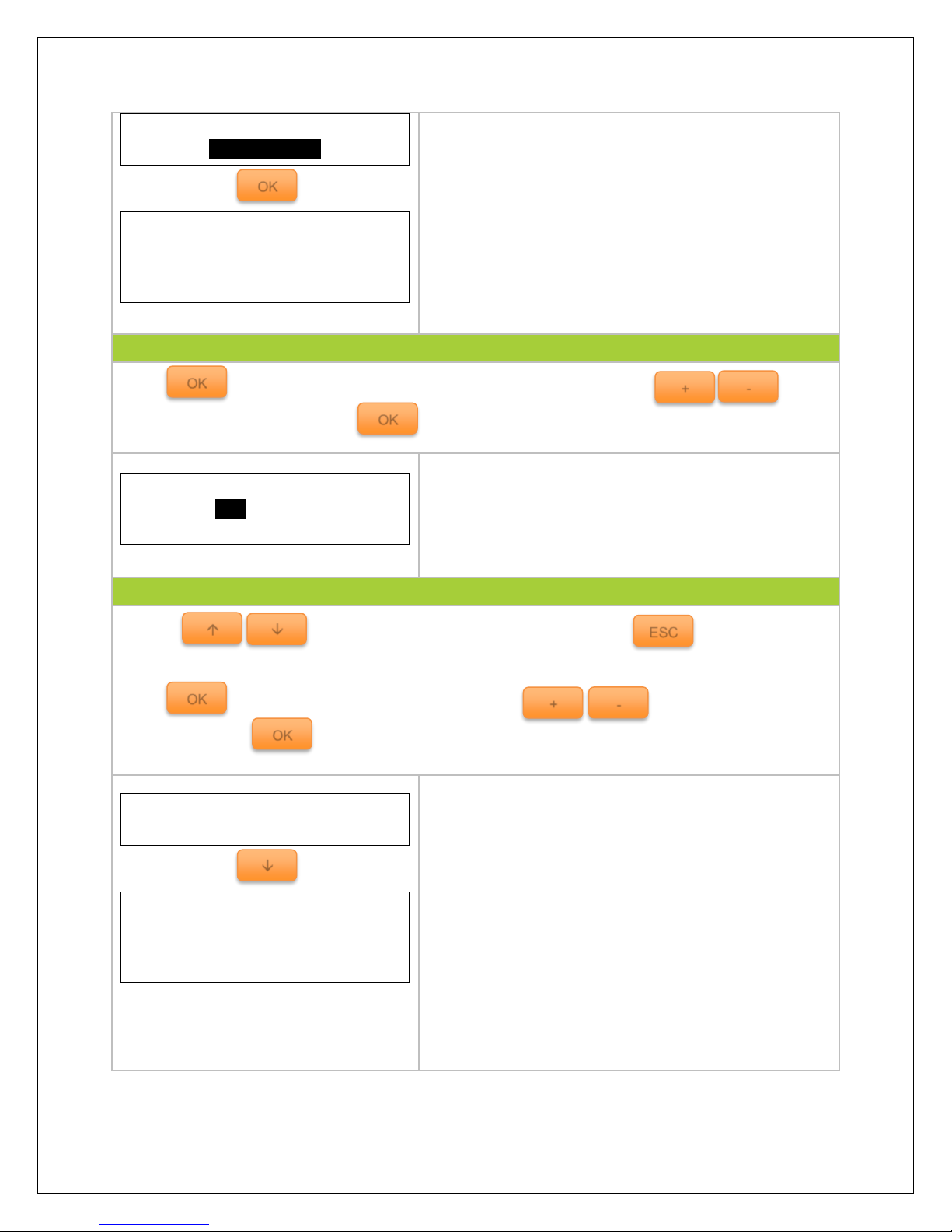
2. Log Info
Use the keys to maneuver through the screens and to access the
menu
Users will be able to see segments of how
Commander is performing when the whole system is
connected through the work log. Any time there is a
change in voltage or amperage it will be logged onto
the Work Log Query. It is recommended that the date
and time be set correctly so that a range of dates can
be selected and analyze solar performance.
Depending on the total amount of Work Logs, users
can cycle through the logs using the (up) and (down)
arrows. Press ESC to go back to the previous log
menu. The logs display battery voltage and battery
current.
Local Temperature
23.4 oC
Batt Temp
25.0 °C
Temp Coefficient
-3mV / °C / 2V
Total Generated
55 kWh/D
Generated Energy
55 kWh/D
PV Power
0.0 W
ESC
No. 1/121
2015-01-23 1:01
Batt Vol 51.6 V
Batt Curr 0.0A
Work Log Query
From 2015-01-23
To 2015-02-01
Total: 121
OK
<1>Work Log
<2> Alarm Log
ESC
Page 20
19
The Alarm Log will display any kind of faults or
warnings that the charge controller experienced while
having the solar system connected. As in the previous
Log, users can cycle through how many alarm logs
are available and observe the data.
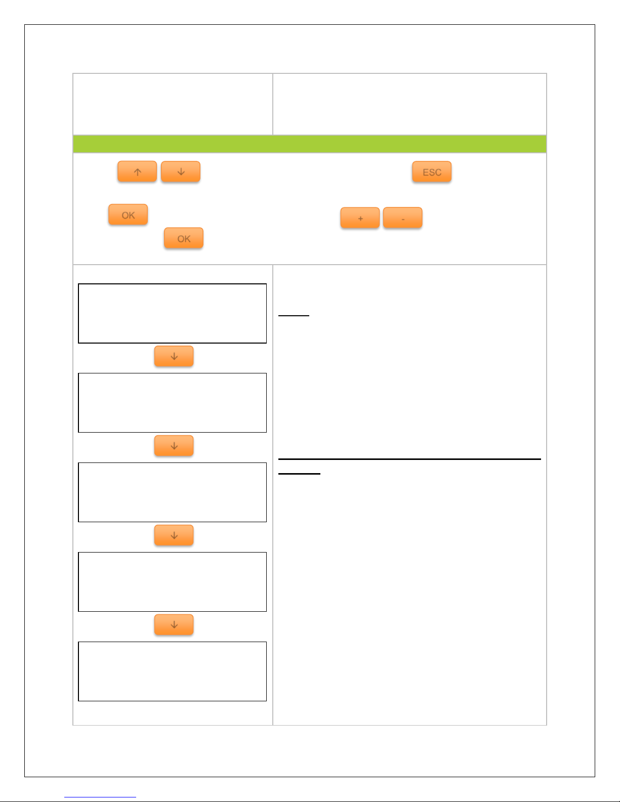
3. Clock Set
Press to highlight the month in the clock set menu and use the keys
to change the parameter. Press to confirm and save the settings.
Users can set the date and time. The clock uses a 24
hour clock.
NOTE: In some models, users might be prompted to
enter a password. Simply put “0” all the way through
and press OK.
4. Local Para Set
Use the keys to maneuver through the screens and to access the
Menu
Press to highlight the parameter and use the keys to change the
parameters. Press to confirm and save the settings.
The Local ID number is the charge controller’s unique
ID when identifying it in a network or utilizing the PC
software to search for the charge controller.
The charge controller’s LCD interface is backlit and
this interface lets you know the amount of seconds the
LCD will be illuminated once the last button is
pressed. The range is from 1-90 seconds and the “–
“symbol indicates the backlight is never off. The
storage log is from 1-30 minutes. It relates to how
often the charge controller collects data and inputs
into the Work Log or Alarm log.
Alarm Log Query
From 2015-01-23
To 2015-02-01
Total: 0
OK
<1>Work Log
<2> Alarm Log
Clock Set
Aug-05-2015
13:16:51
Backlight Time
60 s
Storage Interval
10 min
Local ID
T03-0001
OK
OK
+
-
ESC
OK + -
OK
Page 21
20
NOTE: In some models, users might be prompted to
enter a password. Simply put “0” all the way through
and press OK.
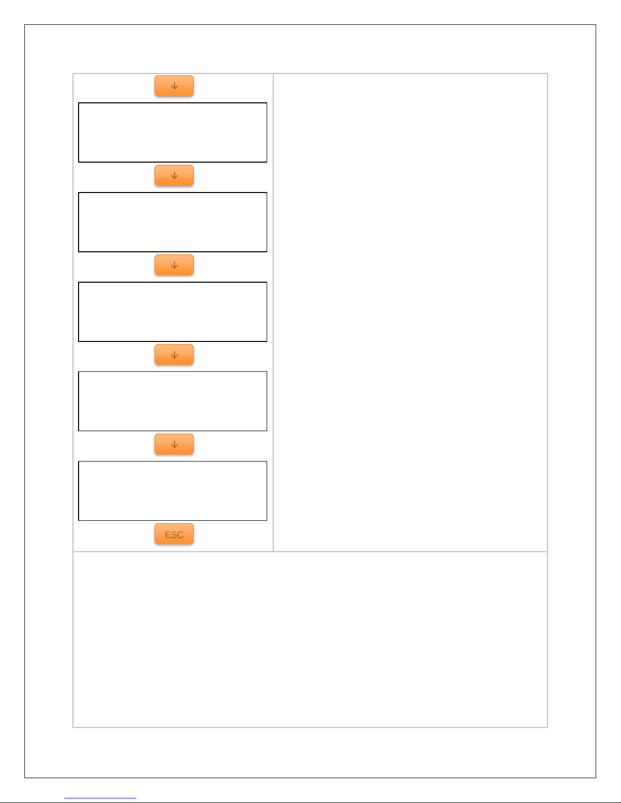
5. Control Para Set
Use the keys to maneuver through the screens and to access the
Menu
Press to highlight the parameter and use the keys to change the
parameter. Press to confirm and save the settings.
Choose between SEALED, FLOODED, GEL, or
USER for Battery type.
Indicates Temperature Compensation. Temperature
fluctuation can affect performance in the system.
Therefore, the purpose of temperature compensation
is to adjust the performance of the system to keep the
system functioning normally.
Choose 12V, 24V, 36V, 48V or AUTO for Rated
voltage.
Parameters for Over-Voltage Disconnect and
Charging Limit.
Parameters for Over-Voltage Reconnect and
Equalization Charge Voltage
Parameters for Boost Charge and Float Charge
voltage
Boost Charge
14.4 V
Float Charge
13.8 V
Over Volt. Rect.
15.0 V
Equalize Charge
14.6 V
Over Volt. Disc.
16.0 V
Charge Limit
15.0 V
Temp Coefficient
-3mV / C ° / 2V
Rated Volt
AUTO
Batt Type
SEALED
Batt AH
10 AH
OK + -
OK
ESC
Page 22
21
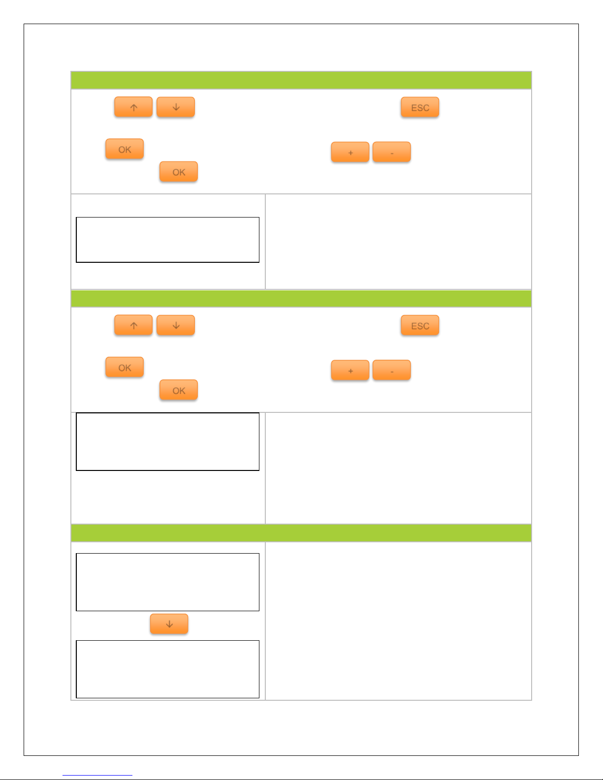
Parameters for Boost Voltage Reconnect and Boost
Under-Voltage Reconnect.
Parameters for under voltage reconnect and under
voltage warning.
Parameters for low voltage disconnect and the
discharging limit.
Parameters for the equalization duration time and the
boost duration time.
Parameters for what constitutes the range for state of
charge and users can select battery managing mode
to be using voltage compensation or SOC.
NOTE:
It is not possible to measure actual SOC, but rather express it as a percentage of some reference.
In this case it is voltage alone (VC) or battery capacity over a time span (SOC).
VC. converts a reading from battery voltage to determine SOC by utilizing the charge controller’s
algorithm for known discharge. It is highly sensitive to temperature changes and battery
disturbances thus having less accurate battery charge statuses.
SOC is more accurate by keeping track of the voltage and current flow in and out of the battery
when reporting battery charge status. The SOC is determined by multiplying current by the time
for which it flowed.
ESC
Batt. Manag.
Char.SOC 100%
Disc.SOC: 30%
Vol.Com. SOC
Equalize Time
120 min
Boost Time
120 min
Low Volt Dis
11.1 V
Discharge Limit
10.6 V
Under Volt Rect
12.2 V
Under Volt Warn
12.0 V
Boost Rect Vol
13.2 V
Low Volt Rect
12.6 V
Page 23
22
6. Sys Password
Use the keys to maneuver through the screens and to access the
Menu
Press to highlight the parameter and use the keys to change the
parameter. Press to confirm and save the settings.
Setting a password for the controller prohibits the user
from programming the controller unless the password
is set.
NOTE: Default Password is “000000” if it prompts the
user to enter a password before they set one.
7. Default Set
Use the keys to maneuver through the screens and to access the
Menu
Press to highlight the parameter and use the keys to change the
parameter. Press to confirm and save the settings.
This interface restores the charge controller to factory
settings which is mainly for user parameters that might
have been set. The second option is to clear the Work
Log which the controller has been keeping track of
thus far.
NOTE: Once parameters are reset, they cannot be
recovered.
8. Dev Msg
This screen provides information regarding the model
type of the charge controller. It includes the model,
software, and SKU number.
Sys Password
Ori.PSW: 000000
NewPSW: 000000
Default Set
No Yes
Clr Log Record
Retain Clear
DSP Msg.
Type: IT6415ND
Ver: v01.00+v02.60
SN: 0420131210000001
ARM Msg.
Type: IT6415ND
Ver: v01.00+v02.60
SN: 0420131210000001
OK + -
OK
ESC
OK + -
OK
ESC
Page 24
23
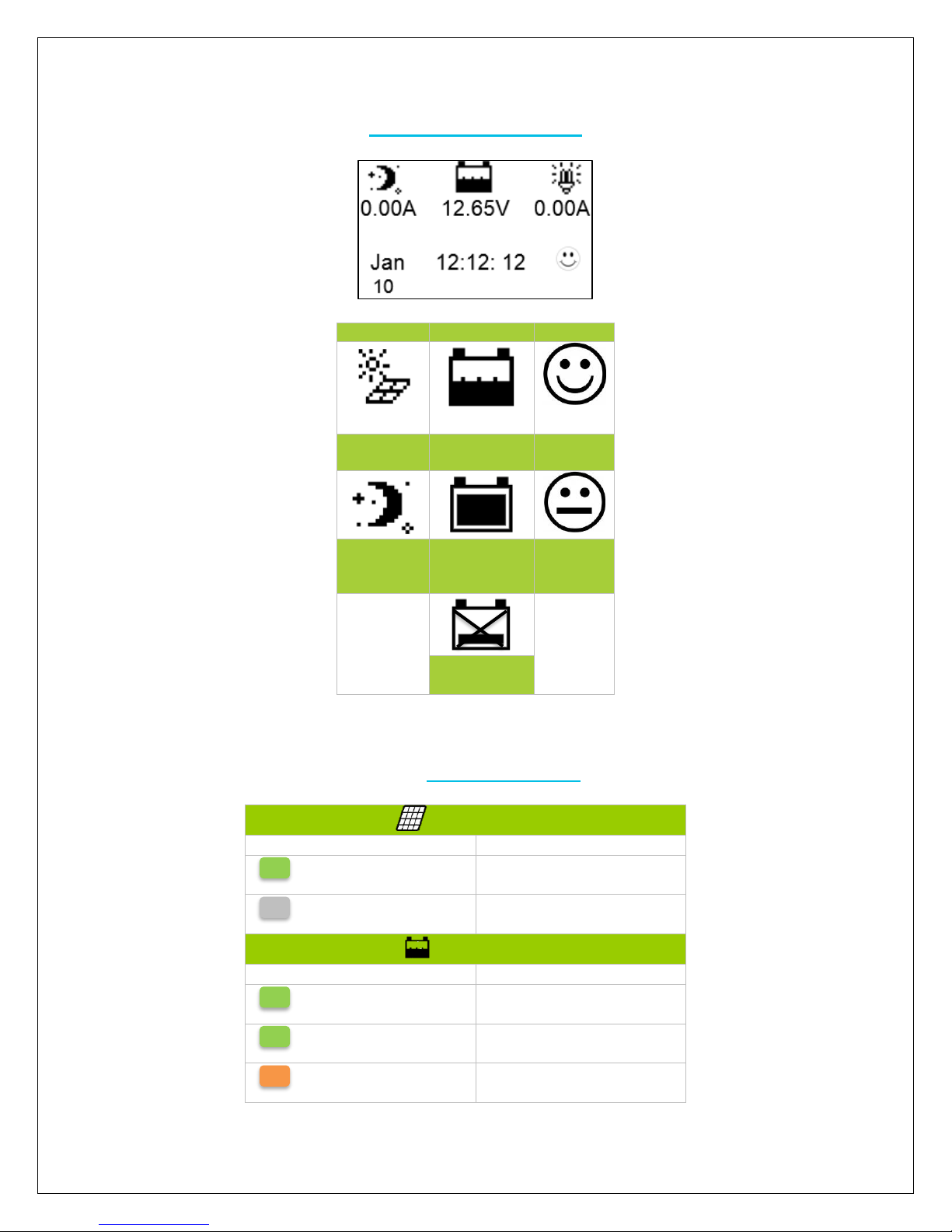
System Status Icons
PV
BATTERY
SYSTEM
Day/ PV
Charging
Battery
Charging
System
Normal
Night/ PV
Not
Charging
Battery
Level Full
System
Fault
Battery Over
Discharge
LED Indicators
Charging LED
Indicator
Status
Green (Blinking)
Charging
Green (Off)
Not Charging
Battery LED
Indicator
Status
Green (Solid)
Normal
Green (Slow Blinking)
Battery Full
Orange (Solid)
Under voltage warning
Page 25
24
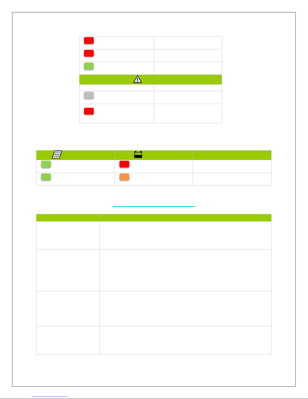
Red (Solid)
Low voltage disconnect
Red (Blinking)
Battery over temperature
Green (Fast Blinking)
High voltage disconnect
Fault LED
Indicator
Status
Red (Off)
Normal
Red (Blinking)
Current is abnormal
Charging overcurrent
PV Overvoltage
The following LED indicators must be occurring at the same time for the Charging LED and
Battery LED
Charging LED
Battery LED
Status
Green (Blinking)
Red (Blinking)
System Voltage Error
Green (Blinking)
Orange (Blinking)
Controller Over Temperature
Commander Protections
Protection
Behavior
PV Array Short
Circuit
When PV shot circuit occurs, the controller will stop charging.
Clear it to resume normal operation
PV Overvoltage
If the PV voltage is larger than maximum input open voltage
150VDC, PV will remain disconnected and warning until the
voltage falls safely below 145V. PV voltage cannot be too high,
otherwise it may damage the controller.
PV Overcurrent
The controller will limit the battery charging current to the
maximum battery current rating. Therefore an over-sized solar
array will not operate at peak power.
PV Reverse Polarity
The controller will not operate if the PV wires are switched. Wire
them correctly to resume normal controller operation.
Page 26
25
Battery Reverse
Polarity
The controller will not operate if the battery wires are switched.
Wire them correctly to resume normal controller operation.
Over-Temperature
If the temperature of the controller heat sink exceeds 85OC, the
controller will automatically start the protection and recover
once conditions are below 75OC
System Status Troubleshooting
Description
Troubleshoot
Charging LED off during
daylight.
Ensure that the PV wires are correctly and tightly secured inside
the charge controller PV terminals. Use a multi-meter to make
sure the poles are correctly connected to the charge controller.
Battery LED orange (solid)
Use a multi-meter to check the battery voltage to confirm reading.
NEVER disconnect battery without disconnecting the solar
panels first. Turn off all loads connected to the battery (if
applicable) and let the battery charge.
Battery LED orange
(blinking)
The charge controller is operating above the maximum
temperature range. Change the location of the charge controller
to a cooler environment. Follow proper installation procedures to
not damage the system.
Battery LED is green and
blinking fast. LCD is
displaying “OVD”
Battery voltage may be larger than over voltage disconnect
voltage. Use a multi-meter to check the battery voltage and
disconnect the PV modules for a more accurate reading.
Fault LED is blinking red
and LCD displays “Over
Volt”
The solar input may be too high. Use a multi-meter to determine
whether the solar panels are sized appropriately to the controller
and battery bank. The charge controller will pause all activity and
resume work activity once it detects a proper voltage range.
Users cannot connect RS-
485 cable
Check that the correct cable is being used and the correct port is
being used. Verify that the correct software is installed.
Page 27
26
Maintenance
WARNING: Risk of Electric Shock! Make sure that all power is turned off before
touching the terminals on the charge controller.
For best controller performance, it is recommended that these tasks be performed from
time to time.
1. Check that controller is mounted in a clean, dry, and ventilated area.
2. Check wiring going into the charge controller and make sure there is no wire
damage or wear.
3. Tighten all terminals and inspect any loose, broken, or burnt up connections.
4. Make sure readings in the LCD and LED are consistent. Take necessary corrective
action.
5. Check to make sure none of the terminals have any corrosion, insulation damage,
high temperature, or any burnt/discoloration marks.
Fusing
Fusing is a recommended in PV systems to provide a safety measure for connections
going from panel to controller and controller to battery. Remember to always use the
recommended wire gauge size based on the PV system and the controller.
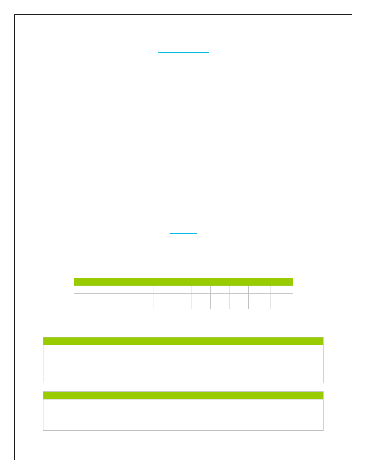
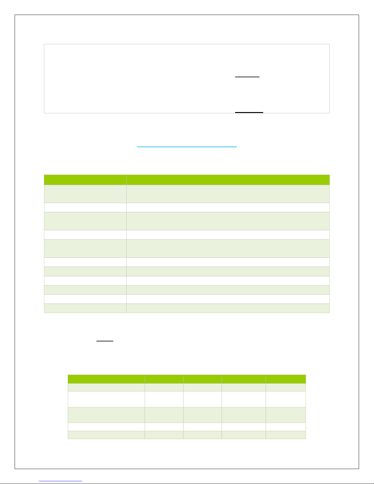
NEC Maximum Current for different Copper Wire Sizes
AWG
16
14
12
10 8 6 4 2
0
Max.
Current
18A
25A
30A
40A
55A
75A
95A
130A
170A
Note: The NEC code requires the overcurrent protection shall not exceed 15A for 14AWG, 20A
for 12 AWG, and 30A for 10AWG copper wire.
Fuse from Controller to Battery
Controller to Battery Fuse = Current Rating of Charge Controller
Ex. 60A MPPT CC = 60A fuse from Controller to Battery
Fuse from Solar Panel(s) to Controller
Ex. 200W; 2 X 100 W panels
**Utilize 1.56 Sizing Factor
Page 28
27
Technical Specifications
Electrical Parameters
Model
Commander 60A MPPT
Nominal system
voltage
12v/24v/36v/48v/ Auto Recognition
Rated Battery Current
60A
Max. Input Short
Current
75A
Battery Voltage Range
8-68V
Max Solar Input
Voltage
150 VDC @ Minimum Working Temperature
138 VDC @ 25°C
MPPT Voltage Range
Vbattery + 2V ~ 108V
Max. Solar Input Power
12V @ 800W | 24V @ 1600W | 36V @ 2400W | 48V @ 3200W
Self-Consumption
1.4W to 2.6W
Grounding
Negative
Communication
RS485 Cable
PV Wire Size
4 AWG
Charging Parameters
NOTE: Under the USER battery setting, the parameters can be adjusted within the boundaries of
the max and min values listed below. All of the following coefficients assume 25oC Standard Testing
Conditions (STC). The following parameters will be (x2) for 24V systems, (x3) for 36V systems, and
(x4) for 48V systems.
Battery Type
SEALED
GEL
FLOODED
USER
High Volt Disconnect
16V
16V
16V
9~17V
Charging limit
voltage
15V
15V
15V
9~17V
Over Voltage
Reconnect
15V
15V
15V
9~17V
Equalization voltage
14.6V
——
14.8V
9~17V
Boost voltage
14.2V
14.4V
14.6V
9~17V
Series:
Total Amperage = I
sc1
= I
sc2
= 5.75A * 1.56
Fuse = minimum of 5.75 * 1.56 = 8.97 = 9A fuse
Parallel
Total Amperage = I
sc1
+ I
sc2
= (5.75A + 5.75A) * 1.56
Fuse = minimum of 11.5 * 1.56 = 17.94 = 18A fuse
Page 29

28
Float voltage
13.8V
13.8V
13.8V
9~17V
Boost return voltage
13.2V
13.2V
13.2V
9~17V
Low voltage
reconnect
12.6V
12.6V
12.6V
9~17V
Under voltage
recover
12.2V
12.2V
12.2V
9~17V
Under voltage
warning
12V
12V
12V
9~17V
Low Voltage
Disconnect
11.1V
11.1V
11.1V
9~17V
Discharging Limit
Voltage
10.6V
10.6V
10.6V
9~17V
Equalize duration
120min
——
120min
0~180min
Boost duration
120min
120min
120min
10~180min
NOTE: The following rules MUST be obliged when setting custom parameters.
Rule 1: High Volt Disconnect > Charging limit voltage ≥ Equalization voltage ≥ Boost
voltage ≥ Float voltage > Boost return voltage;
Rule 2: High Volt Disconnect > Over Voltage Reconnect;
Rule 3: Charging Limit Voltage > Low voltage reconnect > Low voltage disconnect;
Rule 4: Charging Limit Voltage > Under voltage recover > Under voltage warning;
Rule 5: Boost return voltage > Low voltage reconnect;
Charging Parameters Glossary
High Volt Disconnect—users can use the default parameters or assign a rated voltage
value that the charge controller will operate. When and if the charge controller
experiences a voltage higher than what is assigned, it will disconnect itself from the circuit;
ceasing charge.
Charging Limit Voltage—depending on the batteries used, there might be a battery
charging limit voltage that is recommended for the battery. This parameter ensures that
the charge controller does not exceed the default or assigned rated charging limit voltage.
This is usually put into play to optimize and extend the life of the battery. Relatively
speaking, the higher the charging voltage then there is a correlation for reduced battery
efficiency. (Likewise the lower the discharge voltage affects battery efficiency.
Over-voltage Reconnect—In the event a charge controller experiences an over-voltage
condition set by the previous two parameters, then this reconnecting parameter is put into
play to direct the controller when it can connect and safely charge again. Typically overvoltage reconnection is achieved when time has passed (ex. The sun setting), or when
Page 30
29
the over-voltage condition is remedied ultimately reducing the voltage to a user defined
charging voltage.
Equalization Voltage—equalization voltage is a corrective over-charge of the battery.
The user should consult their battery manufacturer regarding specific battery equalization
capacity. This parameter sets the equalization voltage to set the battery at when it reaches
the equalization state.
Boost Voltage—users should check with their battery manufacturer for proper charging
parameters. In this stage, users set the boost voltage where the battery will reach a
voltage level and remain there until the battery undergoes an absorption stage
Float Voltage—once the charge controller recognizes the set float voltage, it will
commence floating. The battery is supposed to be fully charged in his state, and the
charge current is reduced to maintain battery stability levels.
Boost Return Voltage—if at any point, the battery voltage levels registers to be below
the boost return voltage for an extended period amount of time, then the charge controller
will commence the boost stage once again.
Low Voltage Reconnect—this parameter allows loads connected to the system will be
able to operate (not fully) again.
Under-voltage Recover—deals with the loads connected to the system. When batteries
are determined to be low due to them approaching low voltage disconnect, then the loads
will be shut off to give the batteries time to recover. This parameter sets the controller to
shut off the loads until it can reach the low voltage reconnect stage.
Under-voltage Warning—this parameter deals with the batteries themselves
approaching the under-voltage recovery state. The user should minimize loads before the
charge controller approaches a level where it will do this automatically to protect the
battery from discharging
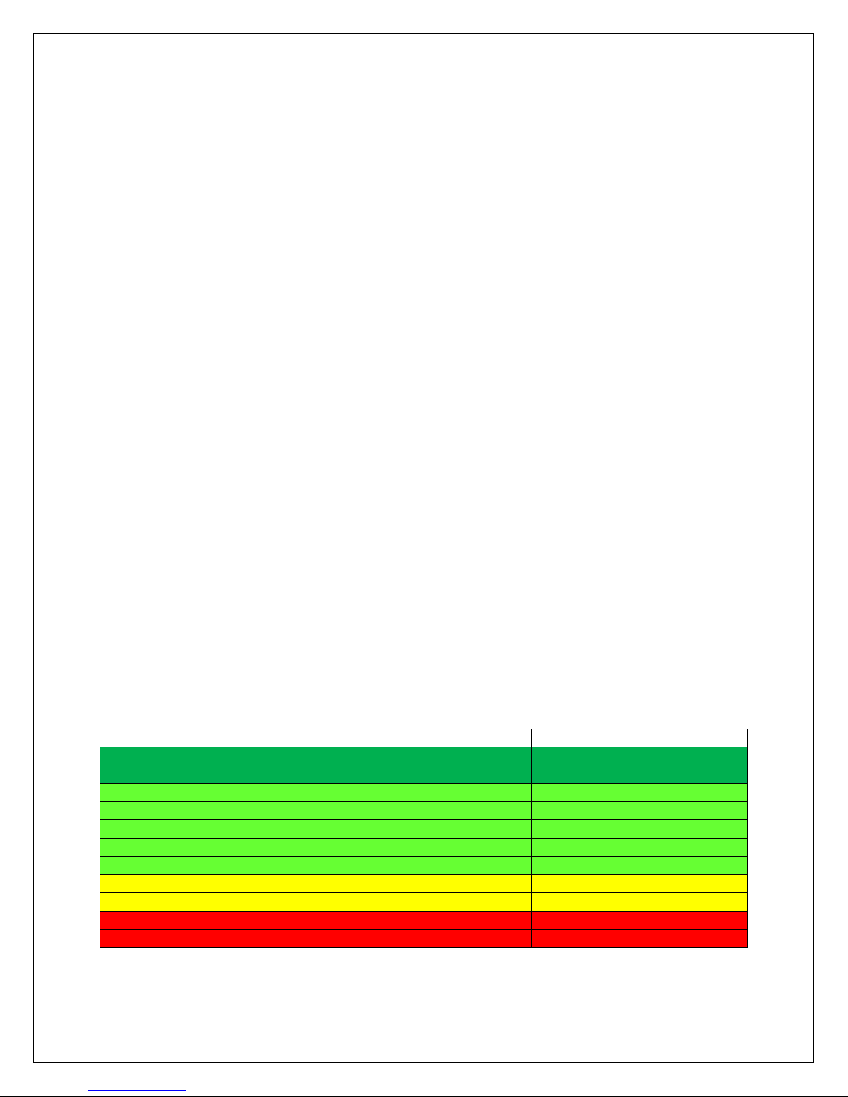
State of Charge
12 V Battery
Volts per Cell
100%
12.7
2.12
90%
12.5
2.08
80%
12.42
2.07
70%
12.32
2.05
60%
12.20
2.03
50%
12.06
2.01
40%
11.9
1.98
30%
11.75
1.96
20%
11.58
1.93
10%
11.31
1.89
0
10.5
1.75
Page 31
30
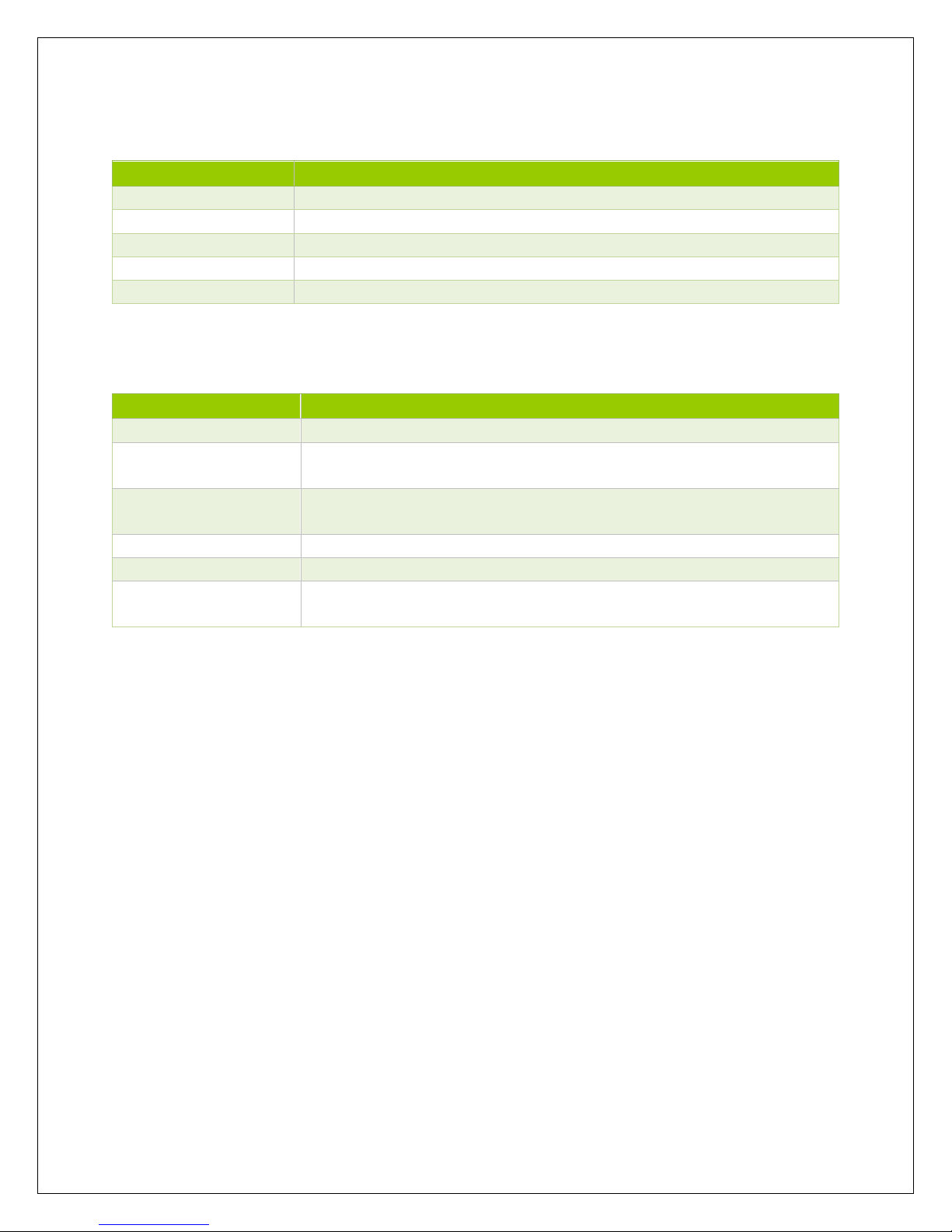
Mechanical Parameters
Model
Commander 60A MPPT
Overall Dimension
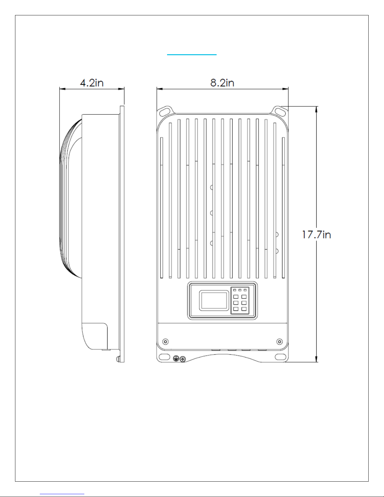
449mm x 208mm x 107mm | 17.7in x 8.2in x 4.2in
Mounting
430mm x 180mm | 16.9in x 7.1in
Max Terminal
4 AWG
Net Weight
5.5 kg | 12.1 lbs.
Mounting Holes
Φ10
Environment Parameters
Model
Commander 60A MPPT
LCD Temperature
-20°C to +70°C | -4oF to 158oF
Working
Temperature
-25°C to +55°C | -13oF to 131oF
Storage
Temperature
-30°C to +85°C | -22oF to 185oF
Humidity
≤95% N.C.
Enclosure
IP20
Altitude
< 5000m (Derate to operate according to IEC60146 at a height
exceeding 1000m)
Page 32
31
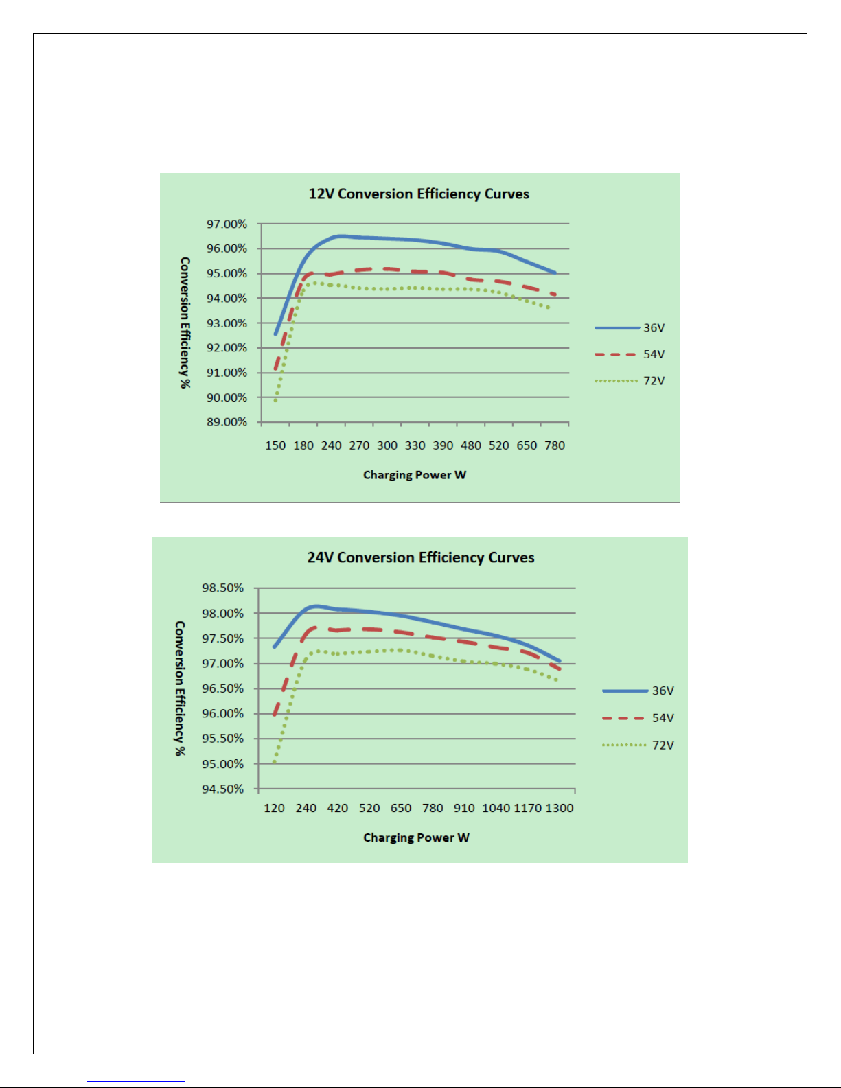
Conversion Efficiency Curves
1. Solar MPPT Voltage (36V, 54V, 72V) / System Voltage (12V)
2. Solar MPPT Voltage (36V, 54V, 72V) / System Voltage (24V)
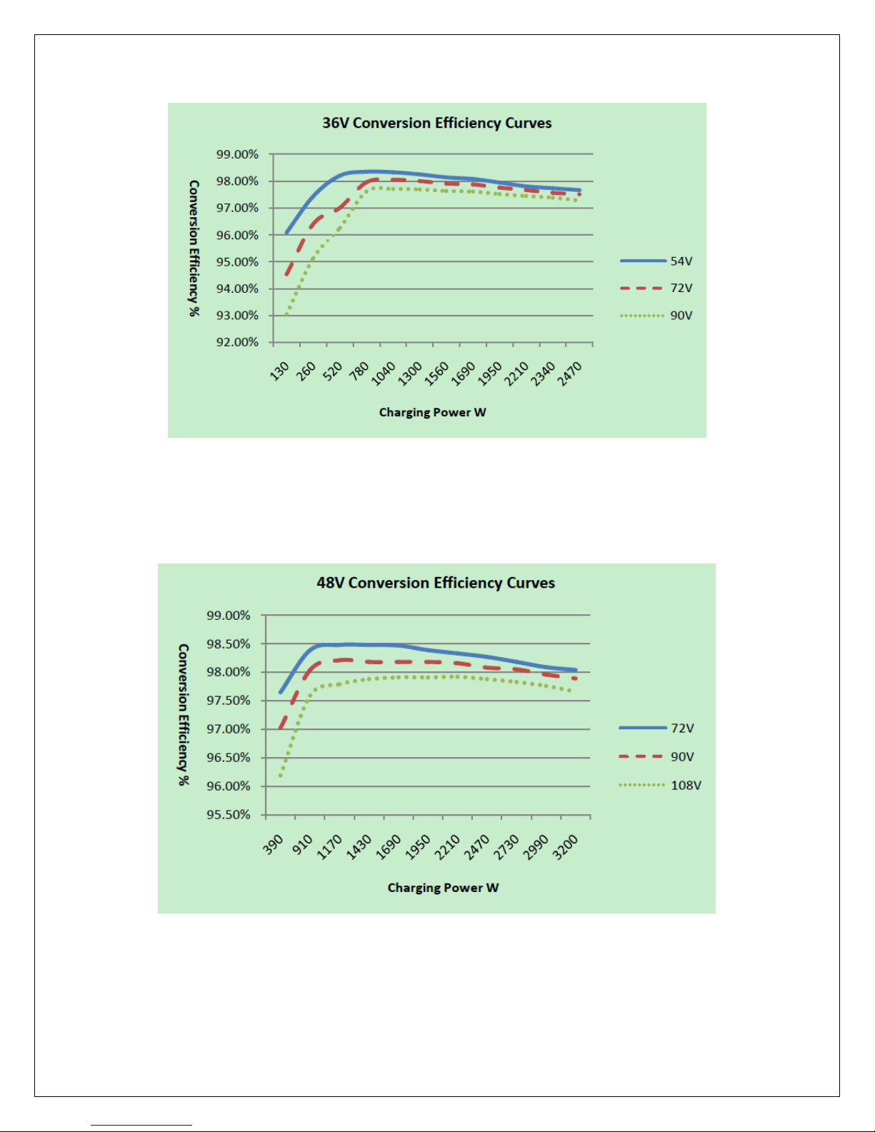
3. Solar MPPT Voltage (54V, 72V, 90V) / System Voltage (36V)
Page 33
32
4. Solar MPPT Voltage (72V, 90V, 108V) / System Voltage (48V)
Page 34
33
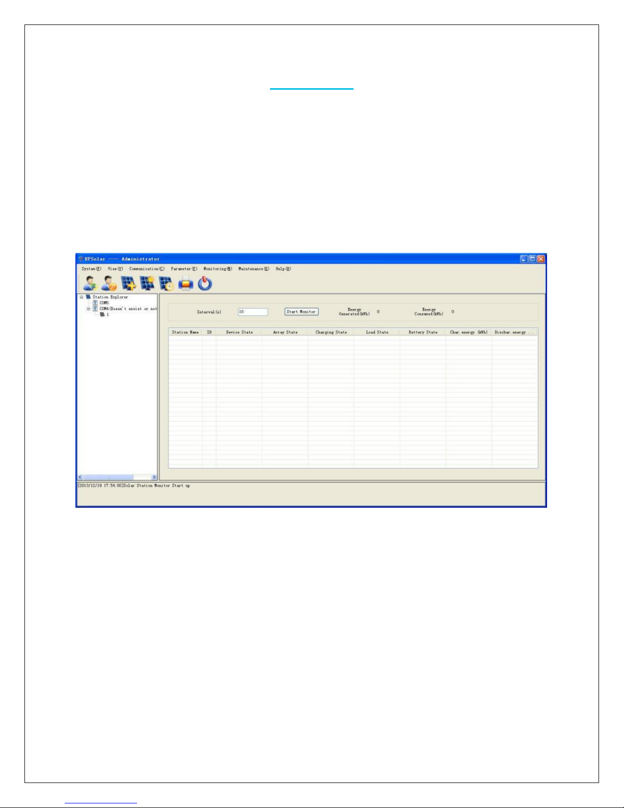
PC Software
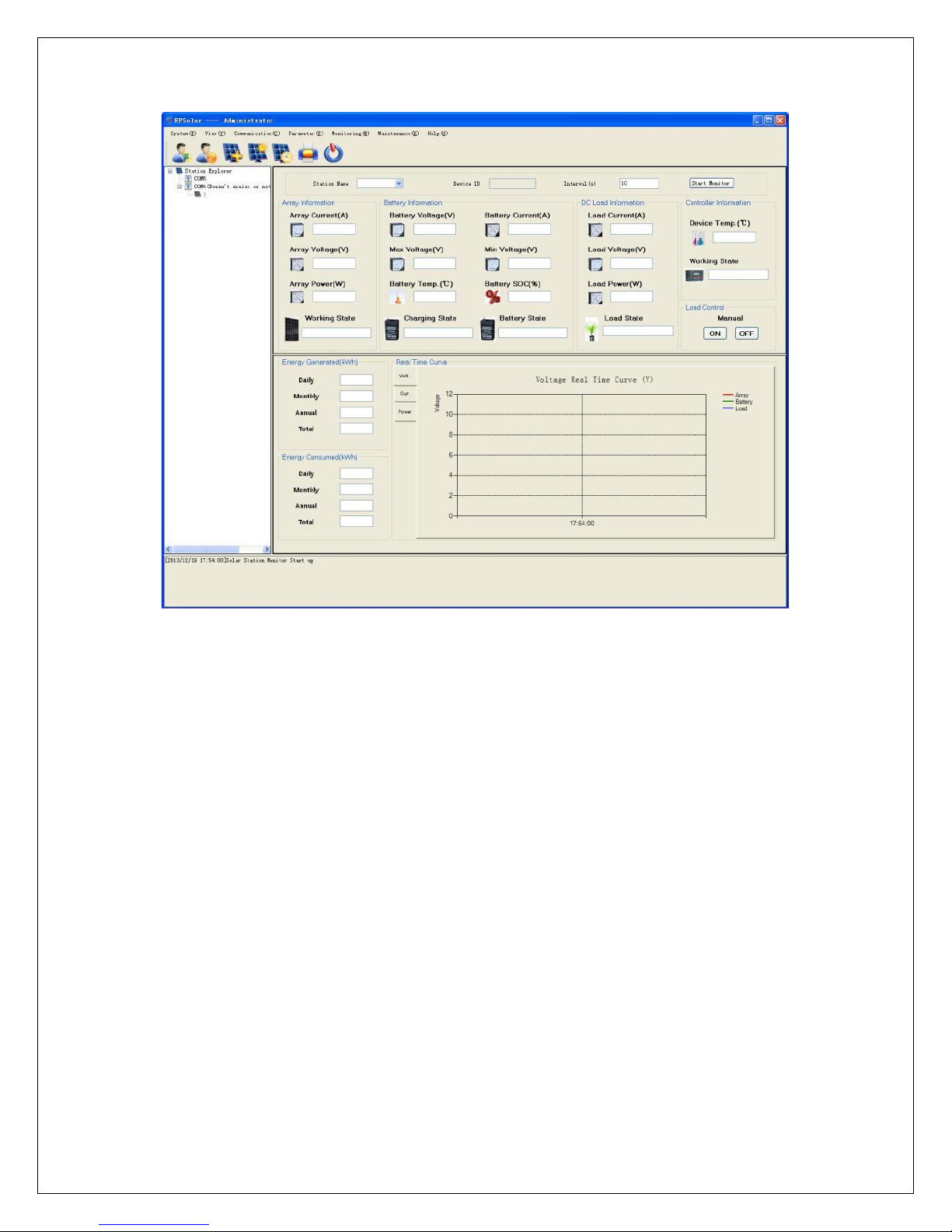
The Commander MPPT charge controller has a special feature where users are able to
remotely monitor the status of their charge controller through the USB connection cable
provided. Remote monitoring can be applied to more than one Commander MPPT charge
controller with their unique identification numbers. Simply plug the USB into your PC and
follow the downloadable instructions.
NOTE: For PC monitoring users will need to enter a username and password.
Username: administrator
Password: 111111
Globe Monitoring
Page 35
34
Real Time Monitoring
Page 36

35
Control Parameter
Load Configuration
Page 37
36
Dimensions
Renogy reserves the right to change the contents of this manual without notice.
For the most up to date manual, visit out download page at www.renogy.com
Revision: 10/27/2017
 Loading...