

Page 1
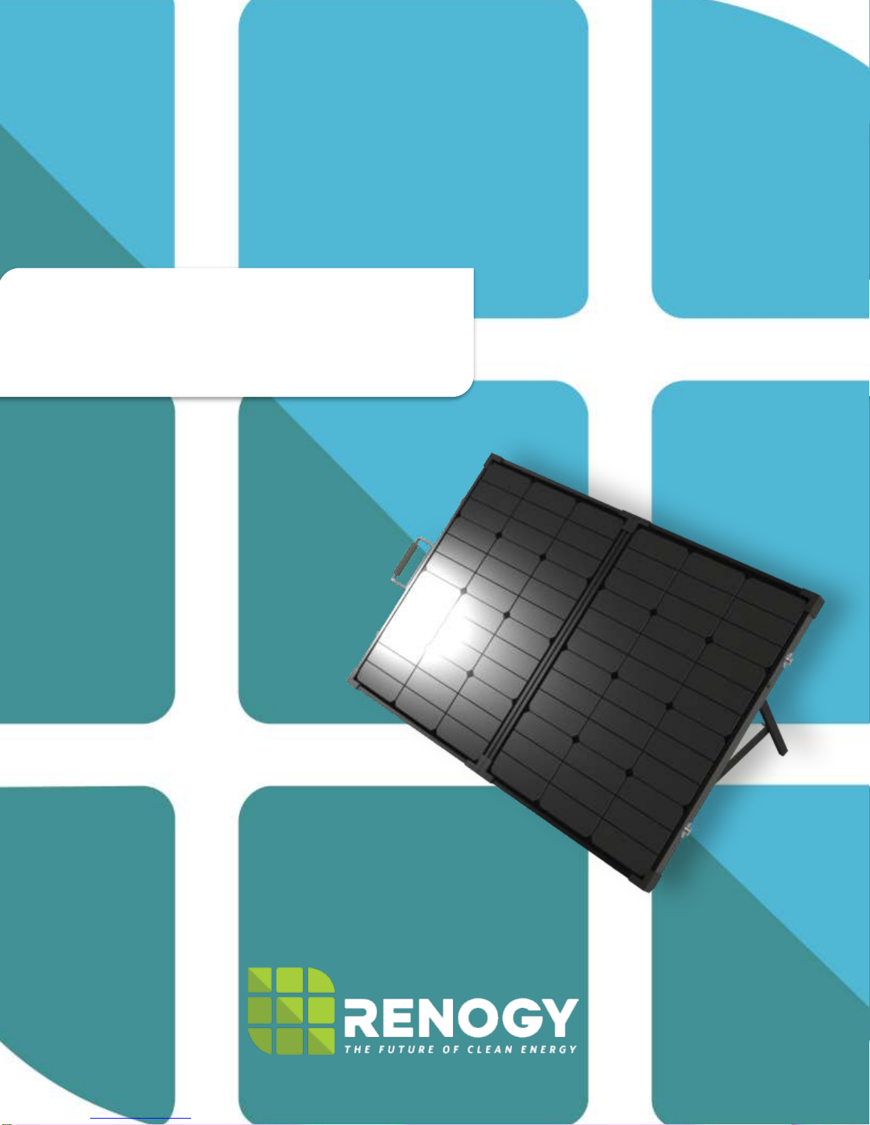
Solar Suitcase
Renogy 60W / 100W Solar Suitcase Manual
14288 Central Ave., Chino, CA 91710
1-800-330-8678
Page 2
Important Safety Instructions
Please save these instructions.
This manual contains important safety, installation, and operating instructions for the charge
controller. The following symbols are used throughout the manual to indicate potentially
dangerous conditions or important safety information.
WARNING: Indicates a potentially dangerous condition. Use extreme caution when
performing this task.
CAUTION: Indicates a critical procedure for safe and proper operation of the controller
NOTE: Indicates a procedure or function that is important to the safe and proper operation
of the controller.
General Safety Information
Read all of the instructions and cautions in the manual before beginning the installation.
There are no serviceable parts for this controller. Do NOT disassemble or attempt to repair
the controller.
Do NOT allow water to enter the controller.
Make sure all connections going into and from the controller are tight.
Charge Controller Safety
NEVER connect the solar panel array to the controller without a battery. Battery must be
connected first.
Ensure input voltage does not exceed 48 VDC to prevent permanent damage. Use the
Open Circuit (Voc) to make sure the voltage does not exceed this value when connecting
panels together.
Do not exceed 10A (VS1024BN) under load.
Battery Safety
Use only sealed lead-acid, flooded, or gel batteries which must be deep cycle.
Explosive battery gases may be present while charging. Be certain there is enough
ventilation to release the gases.
1
Page 3
Be careful when working with large lead acid batteries. Wear eye protection and have
fresh water available in case there is contact with the battery acid.
Carefully read battery manuals before operation.
Do NOT let the positive (+) and negative (-) terminals of the battery touch each other.
Recycle battery when it is replaced.
Over-charging and excessive gas precipitation may damage the battery plates and
activate material shedding on them. Too high of an equalizing charge or too long of one
may cause damage. Please carefully review the specific requirements of the battery used
in the system.
Equalization is carried out only for non-sealed / vented/ flooded / wet cell lead acid
batteries.
Do NOT equalize sealed / VRLA type AGM / Gel cell batteries UNLESS permitted by
battery manufacturer.
WARNING: Do NOT connect any inverters or battery charger into the load terminal of the charge
controller.
WARNING: Once equalization is active in the battery charging, it will not exit this stage unless
there is adequate charging current from the solar panel. There should be NO load on the batteries
when in equalization charging stage.
2
Page 4

Table of Contents
General Information ......................................................................................................................................... 4
Optional Components .................................................................................................................................... 6
Identification of Parts ..................................................................................................................................... 7
Installation ............................................................................................................................................................. 8
Operation ............................................................................................................................................................ 10
1. Monitoring ................................................................................................................................................... 11
2. Device Set .................................................................................................................................................. 12
3. Parameter Set .......................................................................................................................................... 12
4. Load Set ...................................................................................................................................................... 13
6. Test Mode .................................................................................................................................................. 15
7. Password .................................................................................................................................................... 15
8. Batt Mng Mode ......................................................................................................................................... 15
9. Factory Reset ........................................................................................................................................... 15
10. Reboot Device ....................................................................................................................................... 16
System Status Icons .................................................................................................................................... 16
System Status Glossary ............................................................................................................................ 17
Charge Controller Troubleshooting .................................................................................................... 18
Maintenance ...................................................................................................................................................... 19
Frequently Asked Questions .................................................................................................................. 20
Technical Specifications ........................................................................................................................... 21
Charge Controller Electrical Parameters .......................................................................................... 21
Charge Controller Charging Parameters .......................................................................................... 22
Charging Parameters Glossary ............................................................................................................. 23
Charge Controller Threshold Voltage Parameters ....................................................................... 25
Solar Panel Parameters ............................................................................................................................ 25
Dimensions ........................................................................................................................................................ 25
RNG Group Inc. Limited Warranty ....................................................................................................... 29
3
Page 5

General Information
The Renogy Solar Suitcases combine highly efficient Renogy Solar Panels and a fully adjustable
10 Amp ViewStar Series Charge Controller with an LCD Screen to create an easy-to-use, ‘plug
and play’ system.
This system is specifically designed for mobile off-grid applications, where space and weight
limitations are abundant. The Solar Suitcase models support 12V deep cycle battery varieties
such as sealed, lead acid, gel, and flooded. With built-in tilting stands, these panels can be
adjusted at different angles to maximize the power output throughout the seasons.
The alligator clips included in this package make it easy to connect the panel to a battery in
seconds. If one ever needs to connect a battery with a different type of end terminal, the alligator
clips are attached via MC4 Connectors.
Key Features
Dot-matrix, backlit LCD for displaying operating information and data.
Unique dual-timer for the controller’s load terminal.
Full control of parameter settings that can be adjusted.
Sealed, Gel, and Flooded battery option.
4 Stage charging: Bulk, Boost. Float, and Equalization
Temperature compensation and correcting the charging and discharging parameters
automatically, improving battery lifetime.
RJ45 interface for use with the remote meter MT-50, which conveniently checks the
operating parameters of the charge controller
Protection against: overcharging, over-discharging, overload, short-circuit, and reverse
polarity.
Negative ground controller.
Tilting stand for maximum potential.
Convenient storage case for easy transportation.
PWM Technology
The PWM 30ACC-ViewStar utilizes Pulse Width Modulation (PWM) technology for battery
charging. Battery charging is a current based process so controlling the current will control the
battery voltage. For the most accurate return of capacity, and for the prevention of excessive
gassing pressure, the battery is required to be controlled by specified voltage regulation set points
for Absorption, Float, and Equalization charging stages. The charge controller uses automatic
duty cycle conversion, creating pulses of current to charge the battery. The duty cycle is
proportional to the difference between the sensed battery voltage and the specified voltage
regulation set point. Once the battery reached the specified voltage range, pulse current charging
mode allows the battery to react and allows for an acceptable rate of charge for the battery level.
4
Page 6
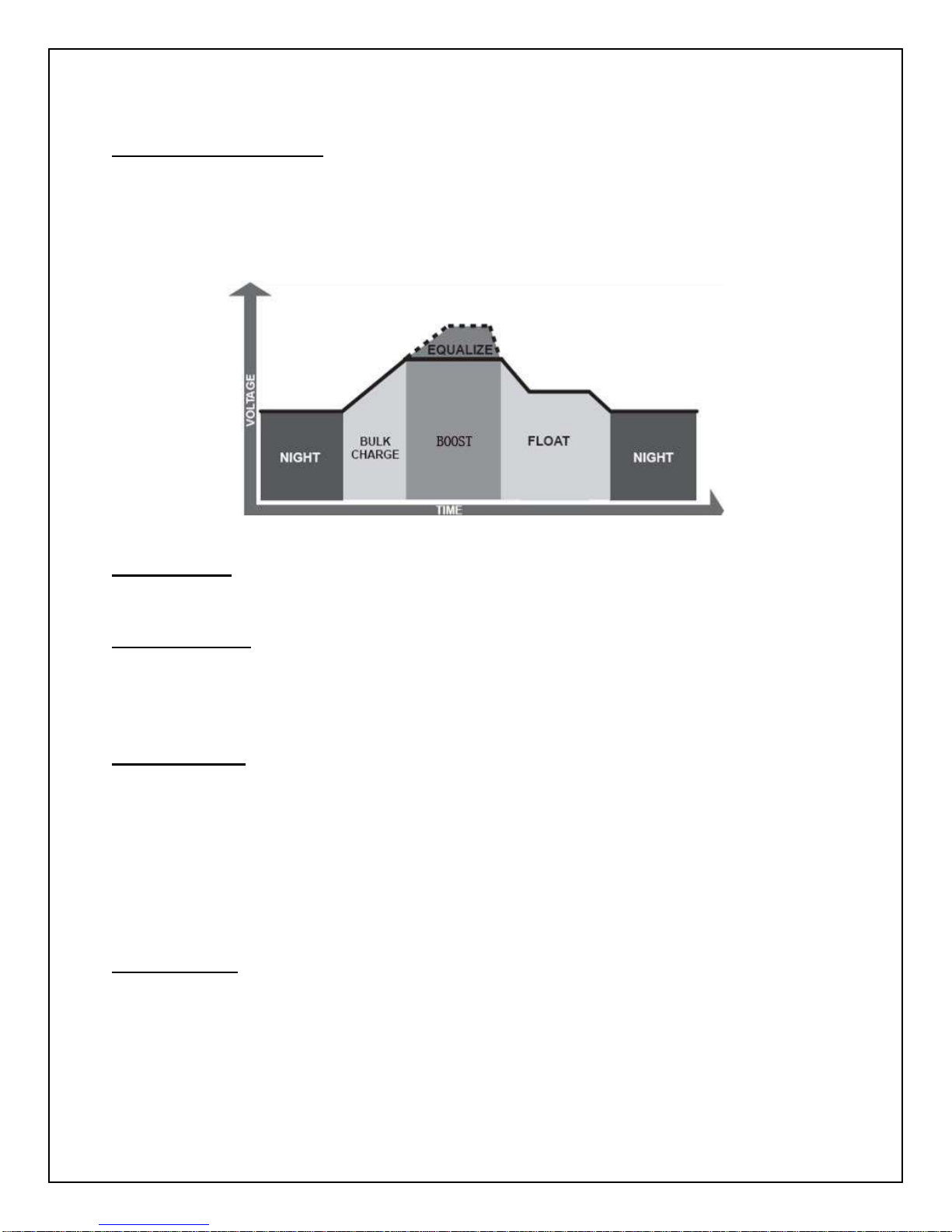
Four Charging Stages
The ViewStar charge controllers have a 4-stage battery charging algorithm for a rapid, efficient,
and safe battery charging. They include: Bulk Charge, Boost Charge, Float Charge, and
Equalization.
Bulk Charge: This algorithm is used for day to day charging. It uses 100% of available solar
power to recharge the battery and is equivalent to constant current.
Boost Charge: When the battery has charged to the Boost voltage set-point, it undergoes an
absorption stage which is equivalent to constant voltage regulation to prevent heating and
excessive gassing in the battery. The default time for this is 120 minutes in the ViewStar
controllers but it can be customizable as needed.
Float Charge: After Boost Charge, the controller will reduce the battery voltage to a float
voltage set point. Once the battery is fully charged, there will be no more chemical reactions and
all the charge current would turn into heat or gas. Because of this, the charge controller will reduce
the voltage charge to smaller quantity, while lightly charging the battery. The purpose for this is
to offset the power consumption while maintaining a full battery storage capacity. In the event that
a load drawn from the battery exceeds the charge current, the controller will no longer be able to
maintain the battery to a Float set point and the controller will end the float charge stage and refer
back to bulk charging.
Equalization: Is carried out every 28 days of the month. It is intentional overcharging of the
battery for a controlled period of time. Certain types of batteries benefit from periodic equalizing
charge, which can stir the electrolyte, balance battery voltage and complete chemical reaction.
Equalizing charge increases the battery voltage, higher than the standard complement voltage,
which gasifies the battery electrolyte.
5
Page 7
WARNING: Once equalization is active in the battery charging, it will not exit this stage unless
Figure 1
Figure 2
there is adequate charging current from the solar panel. There should be NO load on the batteries
when in equalization charging stage.
WARNING: Over-charging and excessive gas precipitation may damage the battery plates and
activate material shedding on them. Too high of equalizing charge or for too long may cause
damage. Please carefully review the specific requirements of the battery used in the system.
WARNING: Equalization may increase battery voltage to a level damaging to sensitive DC loads.
Ensure that all load allowable input voltages are greater than the equalizing charging set point
voltage.
Optional Components
Optional components that require a separate purchase:
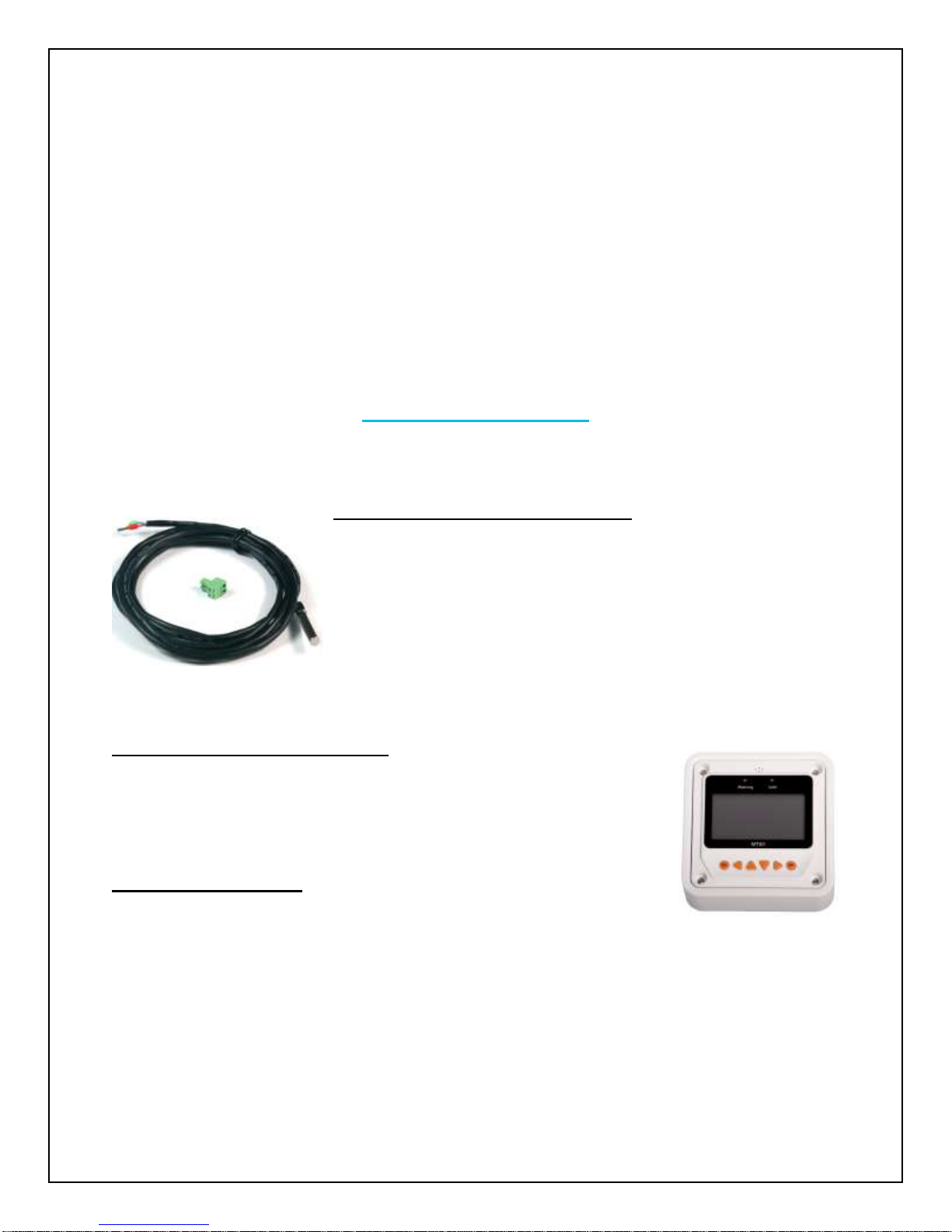
Remote Temperature Sensor (TS-R): Measures the temperature
at the battery and uses this data for very accurate temperature
compensation. The sensor is supplied with a 6.6ft cable length that
connects to the charge controller. (Figure 1)
NOTE: The 10A ViewStar controller comes equipped with a
temperature sensor, but it is ONLY for the charge controller’s
temperature compensation, not the battery’s
temperature compensation.
LCD Display Tracer Meter (MT-50): Allows for real time monitoring of the
charge controller. Perfect for circumstances where the user cannot easily
access the controller or modify its parameters. It is supplied with a 5.9 ft.
cable and a mounting frame that connects to the RJ45 port on the
ViewStar. (Figure 2)
External Battery (RTC): Allows for access to the charge controller’s
saved settings, charge accumulation, and discharge accumulation without
connecting a deep cycle marine battery. It keeps track of the date/time for
automatic equalization charging purposes.
6
Page 8
Identification of Parts
4
1 2 3
5
8
7
6
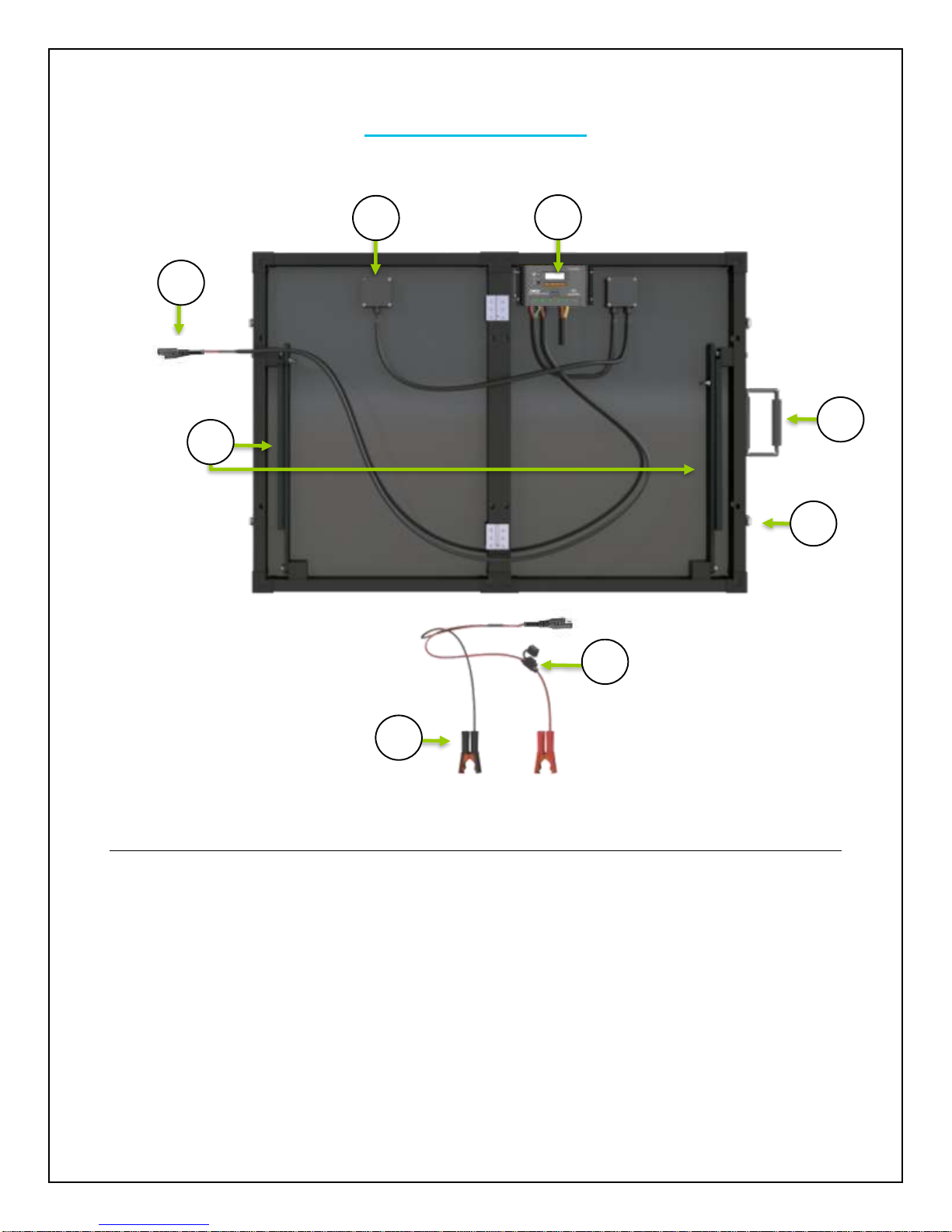
Key Parts
1. 10A ViewStar Charge Controller
2. Junction Box
3. Standard SAE Connector
4. Tilt Stands
5. Battery Alligator Clips
6. In-line fuse
7. Latch
8. Handle
9. Case (Not pictured)
NOTE: Components are the same for the 60W | 100W Solar Suitcase
7
Page 9
Installation
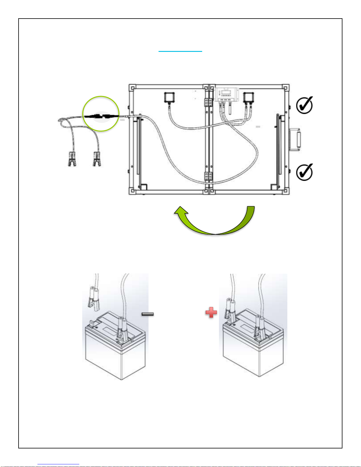
1. Unlatch and unfold unit then connect Standard SAE Connectors
2. Connect Battery Alligator Clips to 12V Battery
8
Page 10
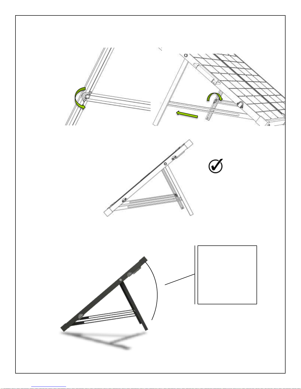
3. Unscrew butterfly nut tilt to desired angle and lock butterfly nut
Summer
𝜃 = 𝐿𝑎𝑡𝑖𝑡𝑢𝑑𝑒 – 15°
Fall and Spring
𝜃 = 𝑎𝑡 𝑙𝑎𝑡𝑖𝑡𝑢𝑑𝑒
Winter
𝜃 = 𝐿𝑎𝑡𝑖𝑡𝑢𝑑𝑒 + 15°
𝜃
To maximize the output, adjust the angle of the suitcase regularly to track the sun’s movement
throughout the season
9
Page 11
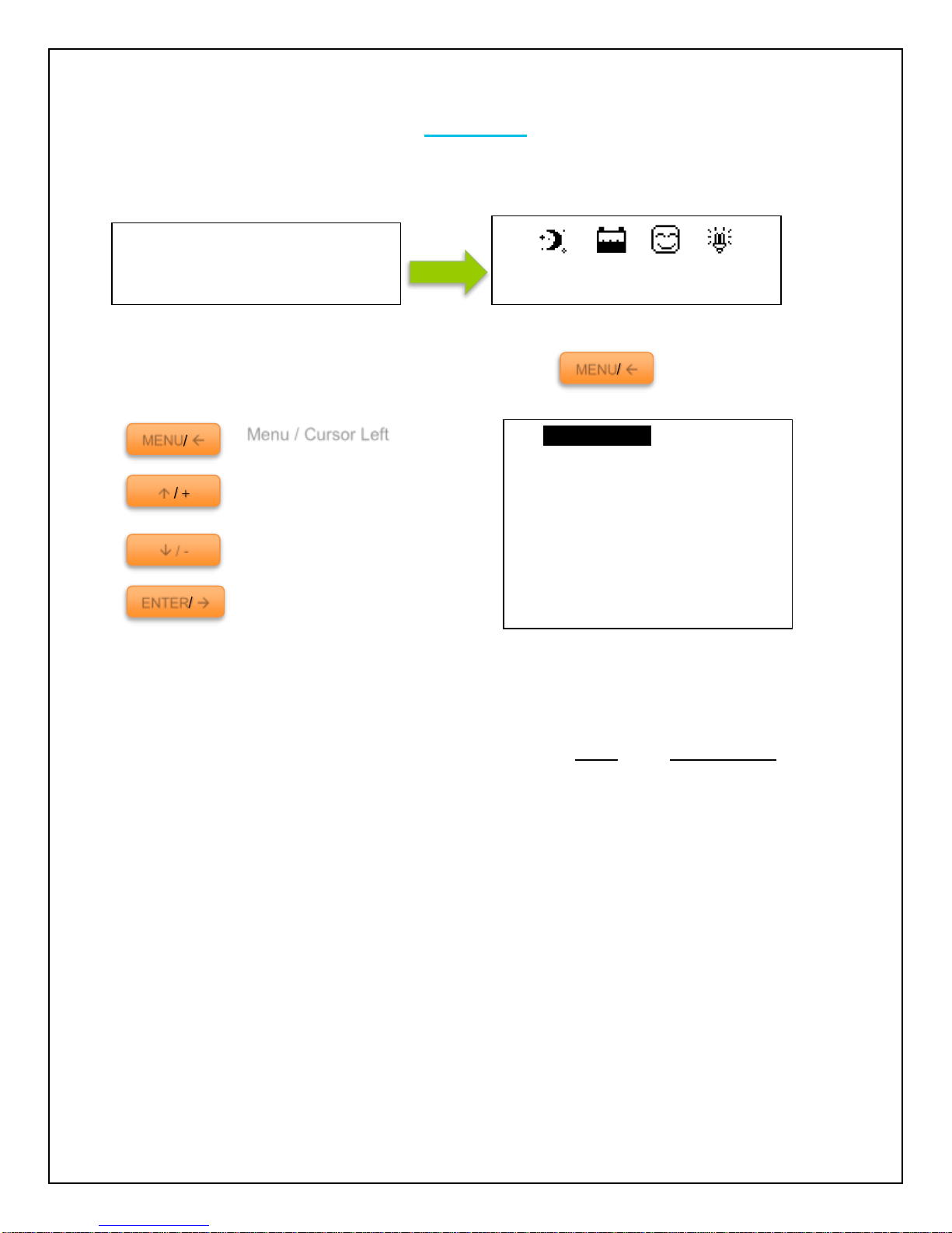
Operation
Menu / Cursor Left
Cursor up / Number add
button
Cursor down / Number
reduce button
Enter / Cursor right button
MENU/
/
/ -
ENTER/
Welcome
V2.37+V2.65
Jan01 12:12:12
1. Monitoring
2. Device Set
3. Parameter Set
4. Load Set
5. Rated Value
6. Test Mode
7. Password
8. Battery Mng Mode
9. Factory Reset
10. Reboot Device
MENU/
After connecting the battery to the charge controller, the controller will turn on automatically. The
user will be prompted by an initialization screen for a few seconds followed by the Default Screen.
Use the following buttons to maneuver
through the menu:
Select to display screen
selection
NOTE: In some models, you might be prompted to enter a password. Simply put “0” all the way
through and press enter.
NOTE: To customize charge parameters, TYPE must be set to USER under 5. Rated Value.
NOTE: The values found in your controller are default values and will not necessarily match the
ones listed. The values on this table are to show the user what the different screens are used for.
NOTE: You do NOT have to program the control. These parameters are for extra features. Once you
connect the battery the settings are automatically synced.
10
Page 12
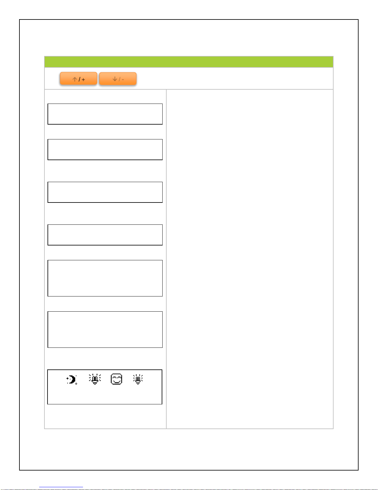
1. Monitoring
Use to maneuver through the screens
Indicates the voltage (V) and amperage (A) that the
solar panel(s) are delivering to the controller
Indicates the voltage (V) and amperage (A) that the
solar panel(s) are delivering to the battery
Indicates the ambient temperature as well as the
SOC (State of charge) of the battery
NOTE: If the remote temperature sensor is connected,
the temperature will reflect that temperature instead
Indicates Load voltage (V) and amperage (A) draw
System status of components—PV panels, Battery
status, Load status, and Device functionality. Refer
to System Status Glossary for more information
The kilowatt hours accumulated in a day, Month, and
total since the controller has been turned on
NOTE: Once the battery is disconnected, the values
are reset to 0 unless there is an external battery
installed on the controller face
System status icons, date, and time. Refer to
System Status Icons for more information
Charg. Energy
Day: 0.00kWh
Mon: 0.00kWh
Total: 0.00kWh
PV: Disconnect
BATT: NoCharge/ Normal
LOAD: On
DEVICE: Normal
LOAD
12.5V 0.0A
TEMP 20.0 C °
SOC 7%
BATT
12.5V 0.0A
PV
0.0V 0.0A
/ -
/
Jan01 12:12:12
11
Page 13
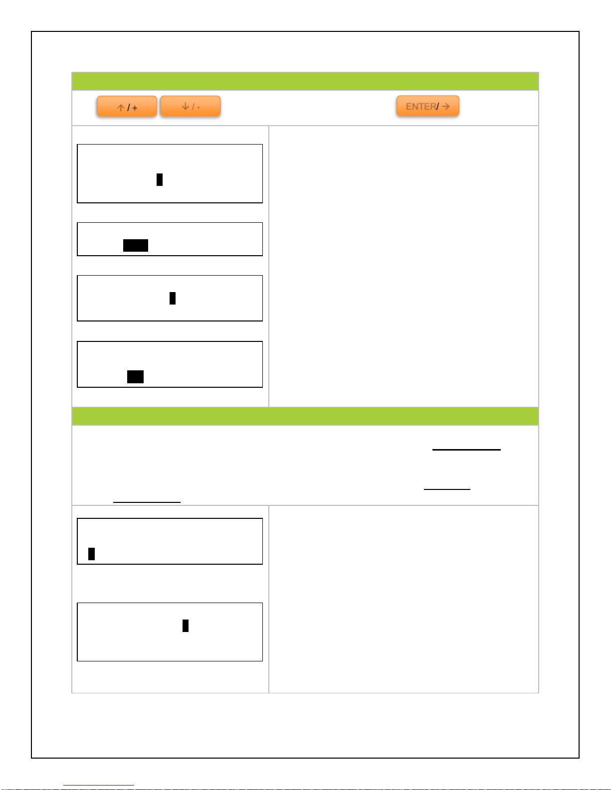
2. Device Set
Use to cycle through the screens. Press to select
Modify the date and time for the charge controller.
Time is displayed in military time (24Hr) and will be
reflected in the default screen. Select Save when
finished. The user will have to select save
parameters after every screen.
Modify the time the backlight is on for the charge
controller. Backlit operation is in effect once the last
button is pressed. The user could use the ID to
connect to a tracer meter and save parameters.
Select Save Parameters when finished.
Choose between Celsius or Fahrenheit when viewing
system status temperature.
3. Parameter Set
NOTE: To customize charge parameters, TYPE must be set to USER under 5. Rated Value.
Otherwise this screen is only for information in regards to the charge parameters.
NOTE: Minimum and maximum charge parameter values can be found in Technical
Specifications
Indicates Temperature Compensation. Temperature
fluctuation can affect performance in the system.
Therefore, the purpose of temperature compensation
is to adjust the performance of the system to keep
the system functioning normally.
Parameters for Over-Voltage Disconnect, Charging
Limit, and Over-Voltage Reconnection.
Device Set
Temp Unit:
>Cel Fah
Device Set
ID: 001
Backlit: 000 sec
Save Parameters?
>Save Cancel
Device Set
Date: 00-00-0000
Time: 00:00:00
Parameter Set
Over Vol. Disc: 16.0V
Charg Lmt: 15.0V
Over Volt. Rect: 15.0V
Parameter Set
Temp Compensate Coeff
-03.0 mV / C ° / 2V
ENTER/
/ -
/
12
Page 14
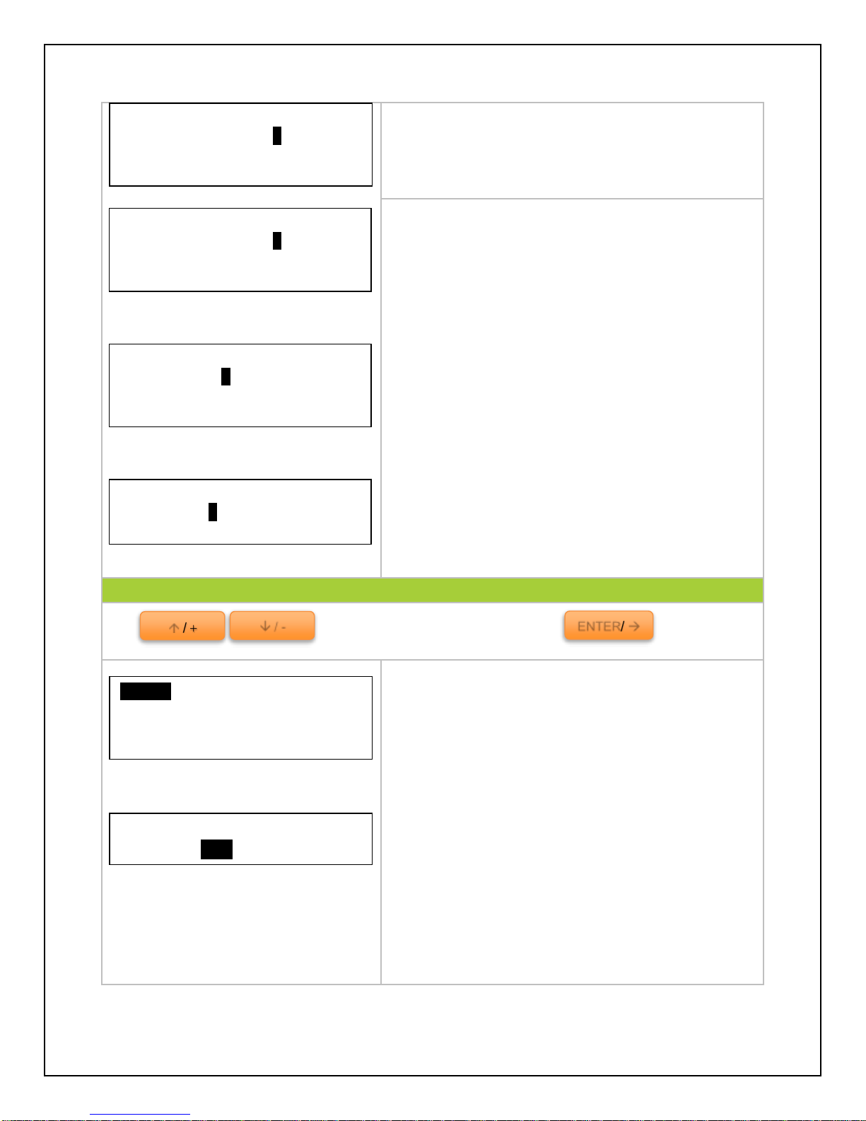
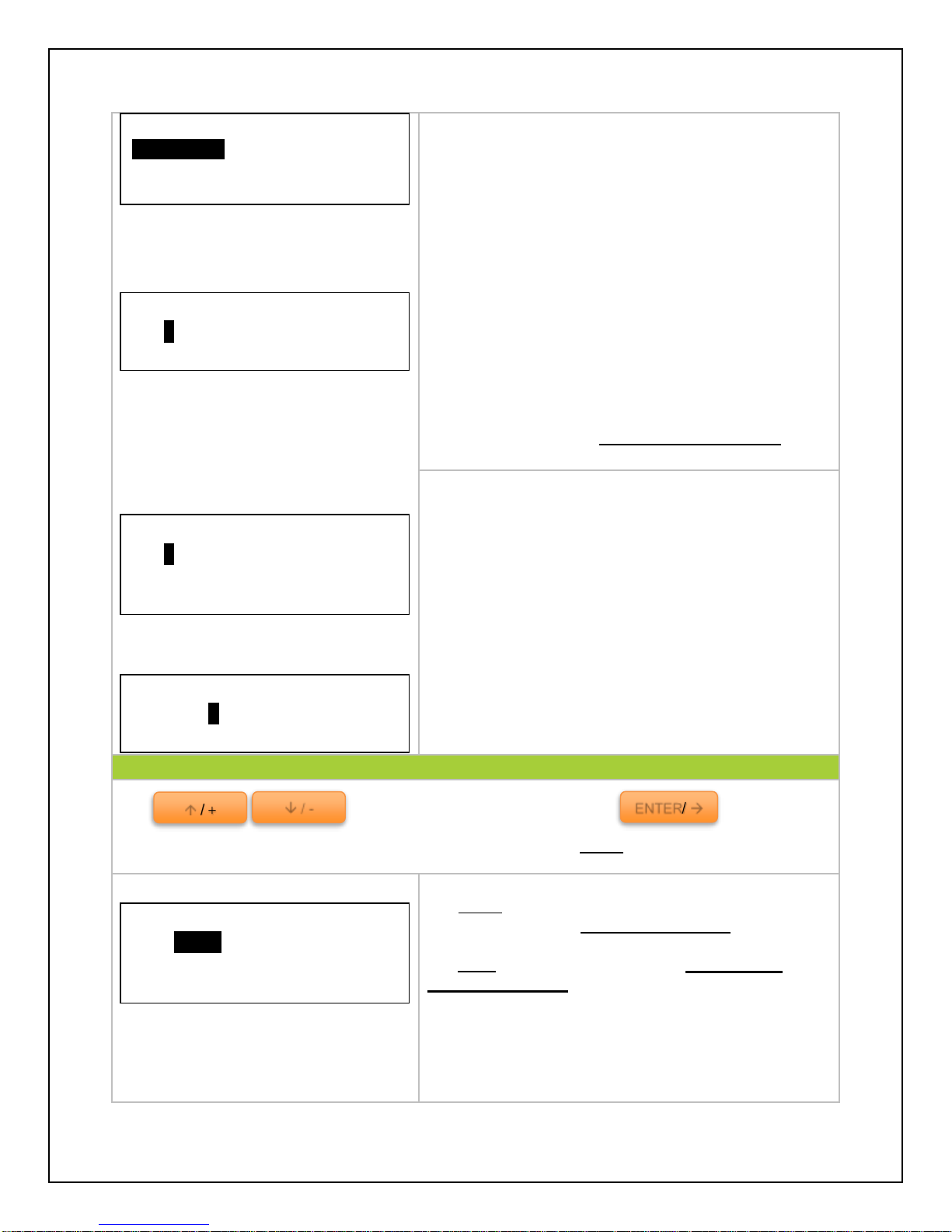
Parameters for commencing Equalization Charging,
Boost Charging, and Float Charging.
Parameters for Boost Voltage Reconnect, Boost
Under-Voltage Reconnect, and Boost Under-Voltage
warning.
Parameters for controller Low Voltage-Reconnect,
Low Voltage-Disconnect, and the Discharge Limit.
Parameter for setting a time duration for when the
controller approaches Equalization Charging and
Boost Charging.
4. Load Set
Use to cycle through the screens. Press to select
A load selection menu allows the user to control the
load terminal activation automatically, manually, or
with a timer.
This function will set the controller to manual mode
by default so the user is able to control when to turn
the load on or off.
NOTE: The user will need to set delay time to “0” so
that manual mode can be instant as opposed to
waiting for the delay time to pass.
Parameter Set
Equal Chrg: 14.6V
Boost Chrg: 14.4V
Float Chrg: 13.8V
Manual Default
>ON OFF
Manual
Light On/Off
Light On+Timer
Timer
ENTER/
/ -
/
Parameter Set
Boost V. Rect: 13.2 V
Under V. Rect: 12.2 V
Under V. Warn: 12.0 V
Parameter Set
Low V. Rect: 12.6V
Low V. Disc: 11.1V
Discharg Lmt: 10.6V
Parameter Set
Equa. Time: 120Min
Boost Time: 120Min
13
Page 15
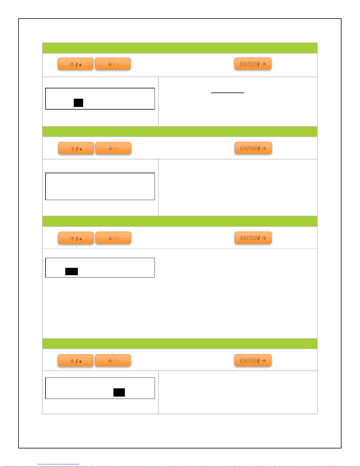
In Light On/Off, the user sets parameters to turn the
load on or off.
The load terminal automatically turns on when the
solar voltage goes BELOW the point of NTTV (Night
Time Threshold Voltage).The load automatically
turns off when the voltage goes ABOVE the point of
DTTV (Day Time Threshold Voltage). There is a
delay between turning the load on or off and can be
programmed to be from 0-99minutes.
NOTE: Minimum and maximum charge parameter
values can be found in Technical Specifications
Similar to Light On/Off parameter with the addition of
a timer that the user sets in order to indicate how
long a load will be on or off. The user also sets an
appropriate time for when it is night time.
NOTE: Timer needs to be activated for it to work.
Using a 24-hour clock, the user is able to set the time
for when the load will turn on and the time for when
the load will turn off.
5. Rated Value
Use to cycle through the screens. Press to select
NOTE: To customize charge parameters, BATT must be set to USER
For BATT: the user selects which battery describes
the one they have—12V, 24V, or AUTO
For Type: The user chooses from Gel, Sealed,
Flooded or USER
The user is able to modify the Amp-hours (AH) to
reflect the actual battery capacity.
NOTE: The Load and PV options will not be adjustable
since the value is based on the charge controller.
Time Control 1
On Time: 19:00:00
Off Time: 06:00:00
Light On + Timer
On: 05.0V Delay: 10m
Off: 06.0V Delay: 10m
Night Time: 12:00
Light On/Off
On: 05.0V Delay: 10m
Off: 06.0V Delay: 10m
Manual
Light On/Off
Light On+Timer
Time
Rated Value
Batt: AUTO 0200AH
Load: 20.0A PV:20.0A
Type: Seal
ENTER/
/ -
/
14
Page 16
6. Test Mode
Use to cycle through the screens. Press to select
Test the load of the charge controller. Once settings
have been set in 4. Load Set, the user is able to test
whether the load will turn on upon direction.
NOTE: Delay must be set to “0” to see immediate
results.
7. Password
Use to cycle through the screens. Press to select
Setting a password for the controller prohibits the
user from programming the controller unless the
password is set.
NOTE: Default Password is “00000” if it prompts the
user to enter a password before they set one.
8. Batt Mng Mode
Use to cycle through the screens. Press to select
Voltage Compensation and State of Charge Battery
Managing modes to determine battery charge status.
NOTE: It is not possible to measure actual SOC, but rather express it as a percentage of some
reference. In this case it is voltage alone (VC) or battery capacity over a time span (SOC).
VC. converts a reading from battery voltage to determine SOC by utilizing the charge
controller’s algorithm for known discharge. It is highly sensitive to temperature changes and battery
disturbances thus having less accurate battery charge statuses.
SOC is more accurate by keeping track of the voltage and current flow in and out of the
battery when reporting battery charge status. The SOC is determined by multiplying current by the
time for which it flowed.
9. Factory Reset
Use to cycle through the screens. Press to select
Reset the controller to factory settings. This will
erase any customized parameters the user may have
set.
Test Mode
Load: > ON OFF
Password
Ori.PSW: 000000
NewPSW: 000000
Factory Reset
>NO YES
ENTER/
/ -
/
ENTER/
/ -
/
ENTER/
/ -
/
ENTER/
/ -
/
Batt Mng Mode
>V.C. SOC
15
Page 17
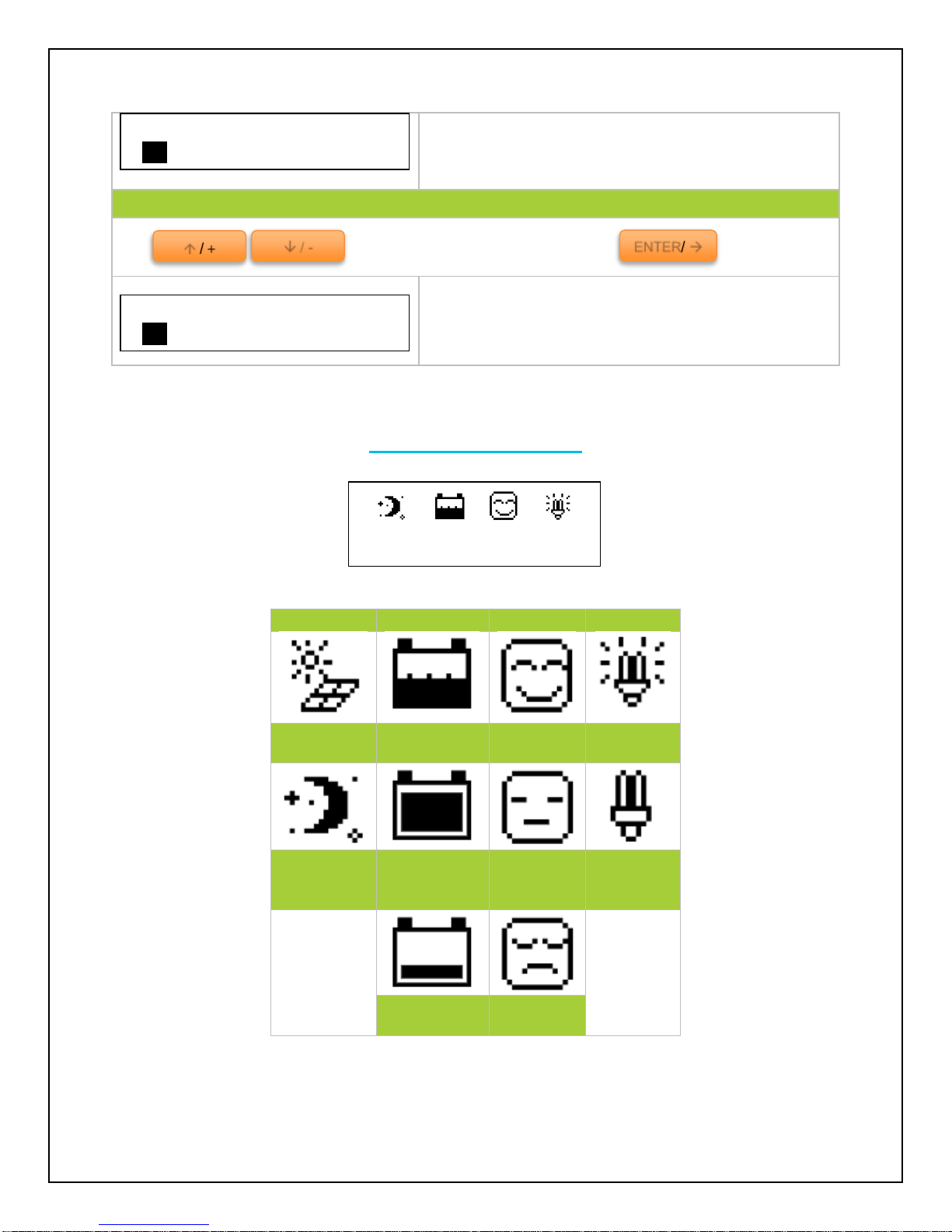
The screen will be followed up by a secondary
screen to make sure a factory reset is what the user
intends to do.
10. Reboot Device
Use to cycle through the screens. Press to select
This parameter will reboot the charge controller
without losing any of the customized settings the
user may have set.
PV
BATTERY
SYSTEM
LOAD
Day/ PV
Charging
Battery
Charging
System
Normal
Load ON
Night/ PV
Not
Charging
Battery
Level Full
UVW
Load OFF
Battery Low
Voltage
LVD
Really to reset?
>NO YES
Reboot Device?
>NO YES
Jan01 12:12:12
ENTER/
/ -
/
System Status Icons
16
Page 18
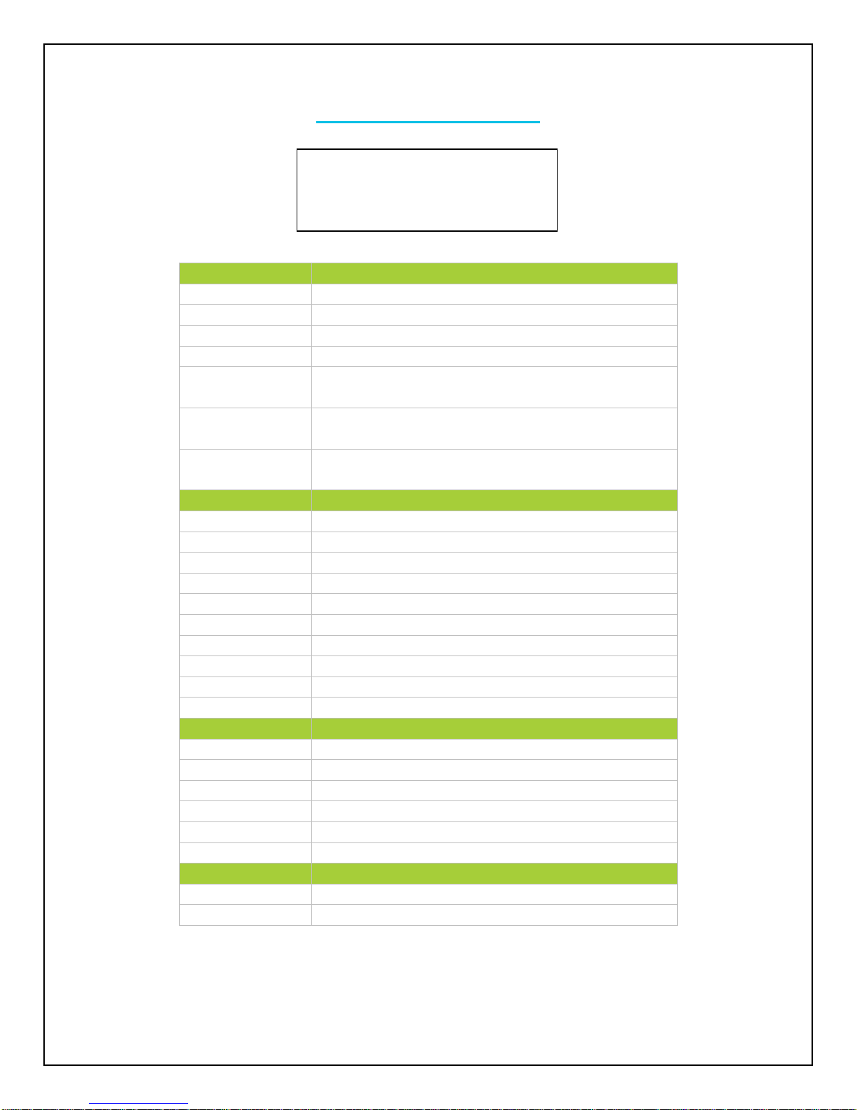
System Status Glossary
PV Status
Meaning
Connect
PV is Connected
Disconnect
PV is Disconnected
Measure Err
Measurement Error at the PV terminal
Over Current
PV is Overcurrent
MOS-I Short
(Metal oxide semiconductor) used for PV reverse
polarity is short.
MOS-C Short
(Metal oxide semiconductor) used for charging is
short.
MOS Break
(Metal oxide semiconductor) in control circuit is
damaged
BATT Status
Meaning
Equalize
Battery is equalizing
Boost
Battery is in boost mode
Float
Battery is in float mode
NoCharge
No charge to battery
LVD
Low voltage disconnect
UVW
Under voltage warning
Normal
Battery is normal
OVD
Over voltage disconnect
Error
Battery experiencing error
OverTemp
Battery is too hot, over temperature
LOAD Status
Meaning
On
Load On
Off
Load Off
Overload
Load is overloaded
Short
Load connection is short
Error
Load experiencing error
MOS Short
Metal oxide semiconductor used in load is short
DEVICE Status
Meaning
Normal
Charge controller normal
OverTemp
Charge controller too hot
PV: Disconnect
BATT: NoCharge/ Normal
LOAD: On
DEVICE: Normal
17
Page 19
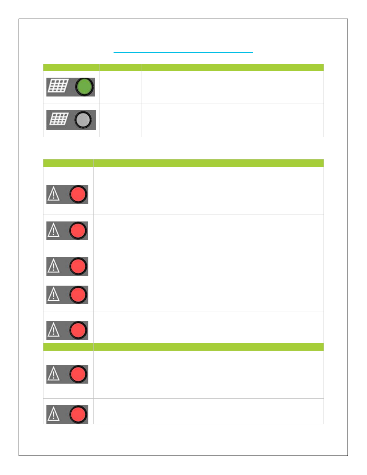
Charge Controller Troubleshooting
Indicator
Status
Description
Troubleshoot
Connect
The controller recognizes the PV
solar panel(s). System is functioning
normally.
N/A
Disconnect
The controller does not recognize the
solar panel(s).
If it is nighttime, the light
will be off. Otherwise
double check that the
poles are not switched.
Indicator
PV Status
Troubleshoot
Measure Err
Check connections and make sure there is not a short
somewhere along the line. Use a multi-meter to determine
whether the panel(s) output is normal prior to connection. Then
reset the controller to factory settings.
OverCurrent
Use a multi-meter to determine whether solar panel(s)
specification match the nominal parameters of the charge
controller.
MOS-I Short
Reset the controller to factory settings. If problem persists,
contact the supplier
MOS-C Short
Reset the controller to factory settings. If problem persists,
contact the supplier
MOS Break
Reset the controller to factory settings. If problem persists,
contact the supplier
Indicator
BATT Status
Troubleshoot
Error
Check that the battery connections are properly connected to the
battery terminals of the charge controller. Make sure there is no
short along the line. Reboot the controller. If problem continues,
reset the controller.
OverTemp
Place the controller in a cooler environment where it will
automatically reconnect
18
Page 20
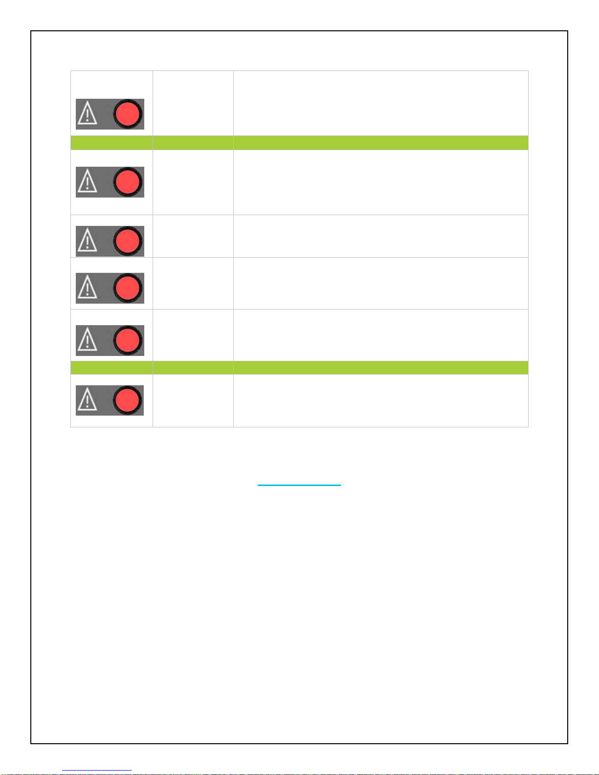
OVD
Check battery parameters and make sure they are suitable to be
used with the charge controller. Use a multi-meter to check
battery voltage to reaffirm the controller’s diagnosis.
Indicator
LOAD Status
Troubleshoot
Overload
Check to make sure the devices connected to the load terminal
are within the load specification. If so, then reduce the number of
loads and it will reconnect automatically.
Short
Check the device wiring and connections going into the load.
There may be a break in the wire.
Error
Reset the controller to factory settings. If problem persists,
contact supplier.
MOS Short
Reset the controller to factory settings. If problem persists,
contact supplier.
Indicator
Device Status
Troubleshoot
OverTemp
Place controller in cooler environment and it will automatically
reconnect.
Maintenance
For best controller performance, it is recommended that these tasks be performed from time to
time.
1. Check that controller is mounted in a clean, dry, and ventilated area.
2. Check wiring going into the charge controller and make sure there is no wire damage or
wear.
3. Tighten all terminals and inspect any loose, broken, or burnt up connections
4. Make sure readings in the LCD and LED are consistent.
19
Page 21

Frequently Asked Questions
Q. What type of batteries can be used with this kit?
A. Any sealed lead acid, gel, or flooded 12V battery (typically used in caravans, motorhomes,
boats etc.) is appropriate for use with this kit.
Q. Can this kit charge a 24V battery?
A. No, because this kit is designed to charge a 12V battery. Technically, it’s possible to change
solar panel connections to enable the kit to work in 24V mode; however, a qualified,
knowledgeable individual should only do this.
Note: unauthorized modification to 24V will void the warranty.
Q. Can the kit charge two or more 12V batteries connected in parallel?
A. Yes, it’s possible if the batteries have the same type and capacity and are wired in parallel as
a single 12V battery bank.
Q. Is there any risk that the solar kit will over charge my battery?
A. One of the functions of the solar charge controller is to ensure that your battery is not over
charged; therefore there is no risk of overcharge.
Q. Can I extend the battery leads?
A. Yes, it’s possible – please choose the same size of cable for extension. However, there longer
the extension, the greater the line loss. Bigger gauge will be required for longer runs.
Q. Do I need to clean the solar panels?
A. Yes, it is recommended for better performance. Dust and dirt should first be swept off the
panel surface using a soft brush. When the sweeping is complete, use a wet cloth to wipe the
panel surface to remove remaining dirt and grime.
Q. Can rain damage the solar kit?
A. The solar panels are fully waterproof (IP66 class), the controller is not. We recommend
protecting the kit from rain, since water into controller may damage the internal circuitry.
20
Page 22

Technical Specifications
Model
VS1024BN
VS2024BN
VS3024BN
Nominal system voltage
12V/24V auto recognition
Rated battery current
10A
20A
30A
Rated load current
10A
20A
30A
Max. battery voltage
32V
Max. Solar Input
48V
Equalize charging voltage
Sealed: 14.6V, Flooded: 14.8V, User-defined: 9~17V
Boost charging voltage
Gel: 14.2V, Sealed: 14.4V, Flooded: 14.6V, User-defined: 9~17V
Float charging voltage
Gel /Sealed /Flooded: 13.8V, User-defined: 9~17V
Low voltage reconnect
voltage
Gel /Sealed /Flooded: 12.6V, User-defined: 9~17V
Low voltage disconnect
voltage
Gel /Sealed /Flooded: 11.1V, User-defined: 9~17V
Self-consumption
≤15mA(12V); ≤10mA(24V);
Grounding
Common negative
Temp. compensation
-3mV/℃/2V
Relative humidity
10%~90% Non-condensation
Communication
RS485 / RJ45 interface
LCD temperature
-20℃ ~ +70℃
Working temperature
-25℃ ~ +55℃
Humidity
≤95% N.C.
Enclosure
IP30
Overall dimension
6.38x3.35x1.57inch
(162x85x40mm)
6.38x3.94x1.97inch
(162x100x50mm)
7.87x4.05x2.28inch
(200x103x58mm)
Terminals
4mm
2
(Up to #12 AWG)
10mm
2
(Up to #8 AWG)
16mm
2
(Up to #6 AWG)
Net weight
0.66 lbs. (0.3kg)
0.88 lbs. (0.4kg)
1.54 lbs. (0.7kg)
Battery Type
Gel, Sealed (AGM), and Flooded
Charge Controller Electrical Parameters
21
Page 23

Charge Controller Charging Parameters
Parameter Battery type
Gel
Sealed
Flooded
High Volt Disconnect
(Over-voltage disconnect)
Default
16.0V; x2/24V
16.0V; x2/24V
16.0V; x2/24V
Max
17.0V; x2/24V
17.0V; x2/24V
17.0V; x2/24V
Min
15.0V; x2/24V
15.0V; x2/24V
15.0V; x2/24V
Charging Limit Voltage
Default
15.0V; x2/24V
15.0V; x2/24V
15.0V; x2/24V
Max
16.0V; x2/24V
16.0V; x2/24V
16.0V; x2/24V
Min
14.0V; x2/24V
14.0V; x2/24V
14.0V; x2/24V
Over Voltage Reconnect
Default
15.0V; x2/24V
15.0V; x2/24V
15.0V; x2/24V
Max
16.0V; x2/24V
16.0V; x2/24V
16.0V; x2/24V
Min
14.0V; x2/24V
14.0V; x2/24V
14.0V; x2/24V
Equalization Voltage
Default
N/A
14.6V; x2/24V
14.8V; x2/24V
Max
N/A
15.2V; x2/24V
15.2V; x2/24V
Min
N/A
14.2V; x2/24V
14.2V; x2/24V
Boost Voltage
Default
14.2V; x2/24V
14.4V; x2/24V
14.6V; x2/24V
Max
15V; x2/24V
15V; x2/24V
15V; x2/24V
Min
13.8V; x2/24V
13.8V; x2/24V
13.8V; x2/24V
Float Voltage
Default
13.8V; x2/24V
13.8V; x2/24V
13.8V; x2/24V
Max
14.2V; x2/24V
14.2V; x2/24V
14.2V; x2/24V
Min
13.2V; x2/24V
13.2V; x2/24V
13.2V; x2/24V
Boost Return Voltage
Default
13.2V; x2/24V
13.2V; x2/24V
13.2V; x2/24V
Max
13.5V; x2/24V
13.5V; x2/24V
13.5V; x2/24V
Min
12.7V; x2/24V
12.7V; x2/24V
12.7V; x2/24V
Low Voltage Reconnect
Default
12.6V; x2/24V
12.6V; x2/24V
12.6V; x2/24V
Max
12.9V; x2/24V
12.9V; x2/24V
12.9V; x2/24V
Min
12.3V; x2/24V
12.3V; x2/24V
12.3V; x2/24V
Under Voltage Recover
Default
12.2V; x2/24V
12.2V; x2/24V
12.2V; x2/24V
Max
12.6V; x2/24V
12.6V; x2/24V
12.6V; x2/24V
Min
11.8V; x2/24V
11.8V; x2/24V
11.8V; x2/24V
Under Voltage Warning
Default
12.0V; x2/24V
12.0V; x2/24V
12.0V; x2/24V
Max
12.4V; x2/24V
12.4V; x2/24V
12.4V; x2/24V
Min
11.6V; x2/24V
11.6V; x2/24V
11.6V; x2/24V
Low Voltage Disconnect
Default
11.1V; x2/24V
11.1V; x2/24V
11.1V; x2/24V
Max
11.8V; x2/24V
11.8V; x2/24V
11.8V; x2/24V
Min
10.5V; x2/24V
10.5V; x2/24V
10.5V; x2/24V
Discharging Limit Voltage
Default
10.6V; x2/24V
10.6V; x2/24V
10.6V; x2/24V
Max
11V; x2/24V
11V; x2/24V
11V; x2/24V
Min
10.5V; x2/24V
10.5V; x2/24V
10.5V; x2/24V
Equalize Duration
N/A
N/A
2 hours
2 hours
Boost Duration
N/A
2 hours
2 hours
2 hours
NOTE: Under the USER battery setting, the parameters can be adjusted within the boundaries of
the max and min values listed below.
22
Page 24

NOTE: The following rules MUST be obliged when setting custom parameters.
Rule 1: High Volt Disconnect > Charging limit voltage ≥ Equalization voltage ≥ Boost
voltage ≥ Float voltage > Boost return voltage;
Rule 2: High Volt Disconnect > Over Voltage Reconnect;
Rule 3: Charging Limit Voltage > Low voltage reconnect > Low voltage disconnect;
Rule 4: Charging Limit Voltage > Under voltage recover > under voltage warning;
Rule 5: Boost return voltage > Low voltage reconnect;
Charging Parameters Glossary
High Volt Disconnect—users can use the default parameters or assign a rated voltage value
that the charge controller will operate. When and if the charge controller experiences a voltage
higher than what is assigned, it will disconnect itself from the circuit; ceasing charge.
Charging Limit Voltage—depending on the batteries used, there might be a battery charging
limit voltage that is recommended for the battery. This parameter ensures that the charge
controller does not exceed the default or assigned rated charging limit voltage. This is usually
put into play to optimize and extend the life of the battery. Relatively speaking, the higher the
charging voltage then there is a correlation for reduced battery efficiency. (Likewise the lower
the discharge voltage affects battery efficiency.
Over-voltage Reconnect—In the event a charge controller experiences an over-voltage
condition set by the previous two parameters, then this reconnecting parameter is put into play
to direct the controller when it can connect and safely charge again. Typically over-voltage
reconnection is achieved when time has passed (ex. The sun setting), or when the over-voltage
condition is remedied ultimately reducing the voltage to a user defined charging voltage.
Equalization Voltage—equalization voltage is a corrective over-charge of the battery. The user
should consult their battery manufacturer regarding specific battery equalization capacity. This
parameter sets the equalization voltage to set the battery at when it reaches the equalization
state.
Boost Voltage—users should check with their battery manufacturer for proper charging
parameters. In this stage, users set the boost voltage where the battery will reach a voltage
level and remain there until the battery undergoes an absorption stage
Float Voltage—once the charge controller recognizes the set float voltage, it will commence
floating. The battery is supposed to be fully charged in his state, and the charge current is
reduced to maintain battery stability levels.
Boost Return Voltage—if at any point, the battery voltage levels registers to be below the
boost return voltage for an extended period amount of time, then the charge controller will
commence the boost stage once again.
23
Page 25

Low Voltage Reconnect—this parameter allows loads connected to the system will be able to
State of Charge
12 V Battery
Volts per Cell
100%
12.7
2.12
90%
12.5
2.08
80%
12.42
2.07
70%
12.32
2.05
60%
12.20
2.03
50%
12.06
2.01
40%
11.9
1.98
30%
11.75
1.96
20%
11.58
1.93
10%
11.31
1.89
0
10.5
1.75
Description
Parameter
Day Time Threshold Voltage (DTTV)
Default
5V; x2/24V
Max
10V; x2/24V
Min
1V; x2/24V
Night Time Threshold Voltage (NTTV)
Default
6V; x2/24V
Max
10V; x2/24V
Min
1V; x2/24V
operate (not fully) again.
Under-voltage Recover—deals with the loads connected to the system. When batteries are
determined to be low due to them approaching low voltage disconnect, then the loads will be
shut off to give the batteries time to recover. This parameter sets the controller to shut off the
loads until it can reach the low voltage reconnect stage.
Under-voltage Warning—this parameter deals with the batteries themselves approaching the
under-voltage recovery state. The user should minimize loads before the charge controller
approaches a level where it will do this automatically to protect the battery from discharging
Low-voltage disconnect—prevents over-discharge of the batteries by automatically
disconnecting any loads. This extends battery life and is the precedent to being in an under
voltage state, recovering from the under voltage state, and finally reconnecting to normal
operational state.
Discharging limit Voltage—the user can set the “discharge” limit of a battery if they choose to
better protect the battery and expand its life. The following chart serves as an example of
voltages and their state of charges. Note that the higher the charging limit and lower the
discharge limit correlates with overall low battery life.
Charge Controller Threshold Voltage Parameters
The following chart demonstrates the parameters when using the Timer under load settings.
24
Page 26
Solar Panel Parameters
Description
60W Parameters
100 W Parameters
Maximum Power
60W
100W
Open Circuit Voltage (Voc)
21.6V
21.6V
Short Circuit Current (Isc)
3.62
6.17A
Maximum Power Voltage (Vmp)
18.0V
17.5V
Maximum Power Current (Imp)
3.34A
5.71A
Cell Type
Monocrystalline
Monocrystalline
Operating Temperature
−40°F to +185°F
−40°F to +185°F
Folded Size
13.6 x 25.4 x 2.8 in
19.9 x 27.2 x 2.4 in
Net Weight
21.20 lbs.
33.10 lbs.
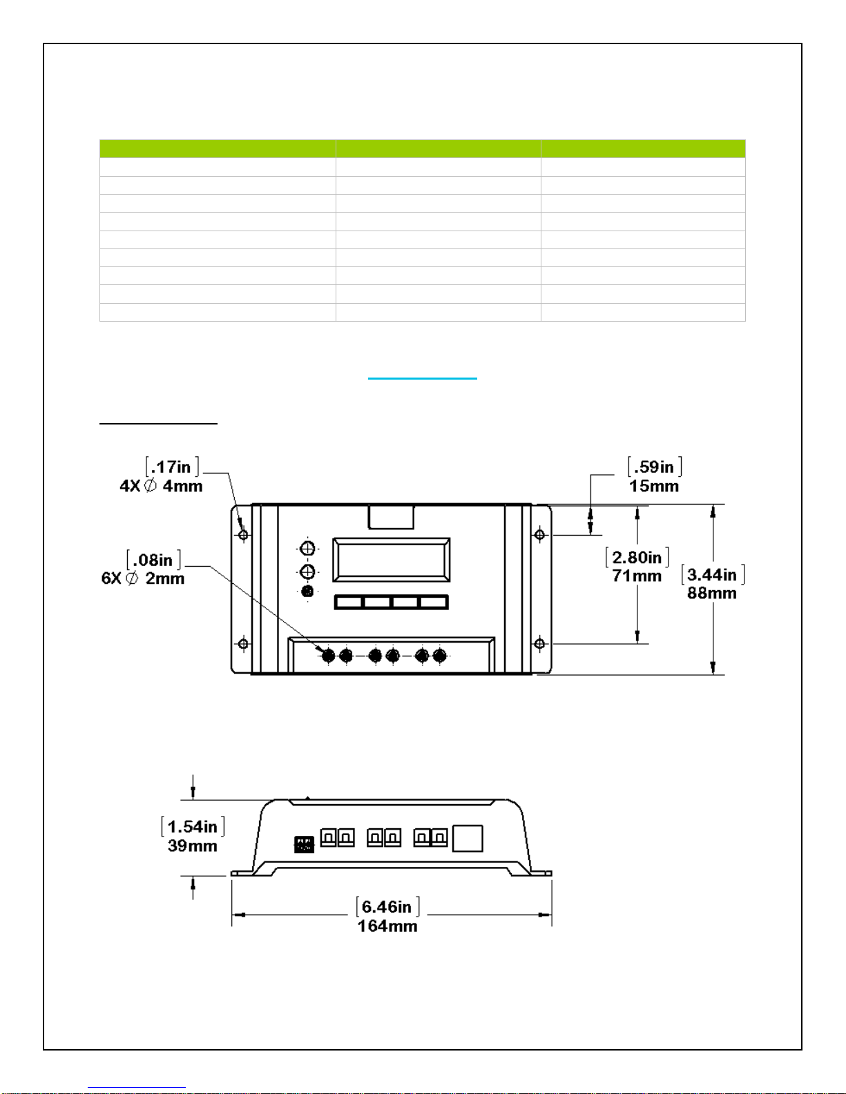
10A VS1024BN
Dimensions
25
Page 27
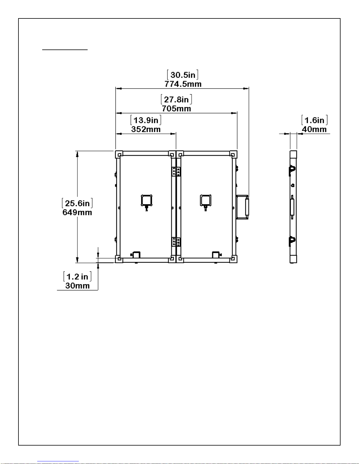
60W Suitcase
26
Page 28
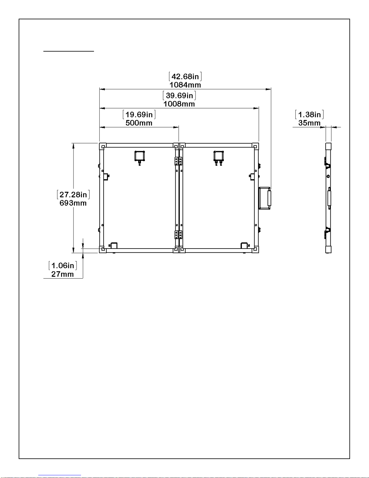
100W Suitcase
27
Page 29

Renogy brand solar panels
(Monocrystalline and polycrystalline
models 150W and below, exclude
bendable models)
5 year product material and workmanship warranty
5 year 95% output warranty
10 year 90% output warranty
25 year 80% output warranty
Renogy brand solar panels
(Monocrystalline and polycrystalline
models 240W and above)
10 year product material and workmanship warranty
5 year 95% output warranty
10 year 90% output warranty
25 year 80% output warranty
Renogy brand solar panels (Suitcase
models excluding charge controller
and wires)
5 year product material and workmanship warranty
5 year 95% output warranty
10 year 90% output warranty
25 year 80% output warranty
Renogy brand solar panels (bendable
models)
5 year product material and workmanship warranty
Renogy brand charge controllers
1 year product material and workmanship warranty
Renogy brand battery inverters
3 year product material and workmanship warranty
Renogy brand mounting hardware
and wiring
1 year product material and workmanship warranty
Other Renogy brand products (LED &
camping gear)
1 year product and material workmanship warranty
RNG Group Inc. Limited Warranty
Thank you for your interest in the products and services of RNG Group Inc. The products
manufactured by RNG Group Inc. (the “Warrantor”) is warranted to be free from defects in
workmanship and materials under normal use and service. The warranty is in effect from the
date of purchase by the user (the “Purchaser”). The warranty covers substantial defects in
material or workmanship including but not limited to: solar panels, charge controllers, battery
inverters, wiring, accessories, etc.
Warranty period for various components:
**Please note that all outsourced products will not be covered by RNG Group Inc. limited
warranty. Instead, outsourced products will be covered under the original manufacturer’s
warranty, if applicable.
28
Page 30

Update: July 9, 2015
For warranty outside the United States, the Purchaser should contact the Warrantor for specific
warranty claims.
The warranty extends only to the original purchaser of the Warrantor’s products. Products or
components that have been serviced or replaced under their warranty period do not receive
extended warranties. Instead, the serviced/replaced products will abide to the original warranty
period issued when first purchased.
The warranty does NOT cover any failures that result from incorrect handling, product
modifications, installation, natural elements, excessive or deficient energy supply, chemicals, or
improper troubleshooting. It is the sole responsibility of the Purchaser to communicate to the
Warrantor of any issues experienced with the product. If the Warrantor determines that the
problem with the product is not due to a manufacturing or workmanship defect, then the
Purchaser is responsible for all costs necessary to repair and transport the product back to the
original Purchaser.
If the Purchaser experiences any difficulty with a potentially defective product, it is their
responsibility to contact the Warrantor’s Technical Support Team. The technicians will offer
steps and procedures to repair a product or require the Purchaser to ship the product to the
Technical Team if needed. Based on the outcome, the warranty service will then be in effect.
The Warrantor does not make any other warranties or conditions not explicitly defined on
this page. Under no circumstances will the Warrantor, its employees, and its
representatives be liable or responsible for any loss of use, business interruption, lost
profits, lost data, and indirect/special/incidental consequential damage of any kind
regardless of the form of action. They are neither liable for injury to any persons or
property incurred through the use or sale of the equipment. The Warrantor assumes no
liability for incidental or consequential damages of any kind.
RNG Group Inc. (the “Warrantor”)
14288 Central Ave.
Chino, CA 91710
Phone: 1-800-330-8678
Fax: 888-543-1164
Email Inquiries:
General: [email protected]
Sales: [email protected]
Technical Support: [email protected]
29
 Loading...