

Page 1
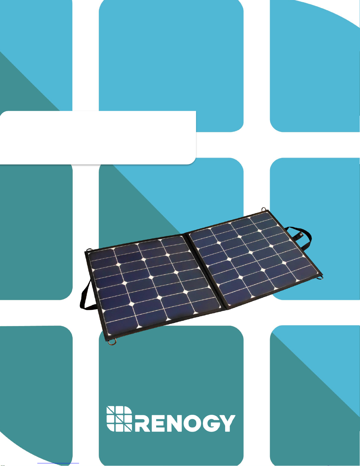
Renogy 100W & 50W Eclipse
Lightweight Suitcase
2775 E. Philadelphia St., Ontario, CA 91761
1-800-330-8678
Page 2

1
Important Safety Instructions
Please save these instructions.
This manual contains important safety, installation, and operating instructions. The following
symbols are used throughout the manual to indicate potentially dangerous conditions or important
safety information.
WARNING: Indicates a potentially dangerous condition. Use extreme caution when
performing this task.
CAUTION: Indicates a critical procedure for safe and proper operation of the controller
NOTE: Indicates a procedure or function that is important to the safe and proper operation
of the controller.
General Safety Information
• Read all the instructions and cautions in
the manual before beginning the
installation.
• There are no serviceable parts for this
controller. Do NOT disassemble or
attempt to repair the controller.
• Make sure all connections going into and
from the controller are tight.
Battery Safety
• Use only sealed lead-acid, flooded, gel or
lithium batteries which must be deep
cycle.
• Explosive battery gases may be present
while charging. Be certain there is
enough ventilation to release the gases.
• Be careful when working with large lead
acid batteries. Wear eye protection and
have fresh water available in case there
is contact with the battery acid.
• Carefully read battery manuals before
operation.
• Do NOT let the positive (+) and negative
(-) terminals of the battery touch each
other.
• Recycle battery when it is replaced.
• Over-charging and excessive gas
precipitation may damage the battery
plates and activate material shedding on
them. Too high of an equalizing charge
or too long of one may cause damage.
Please carefully review the specific
requirements of the battery used in the
system.
• Equalization is carried out only for nonsealed / vented/ flooded / wet cell lead
acid batteries.
• Do NOT equalize sealed / VRLA type
AGM / Gel cell batteries UNLESS
permitted by battery manufacturer.
Page 3

2
Table of Contents
General Information ............................................................................................................................................ 3
Included Components ....................................................................................................................................... 4
Controller Panel Structure .............................................................................................................................. 5
Controller Operation ........................................................................................................................................... 6
Normal Sequencing Display ..................................................................................................................... 6
Setting Menu on LCD Screen .................................................................................................................. 6
System Status Icons ........................................................................................................................................... 8
Error Code List .................................................................................................................................................. 8
System Status Troubleshooting ................................................................................................................. 8
Maintenance ............................................................................................................................................................. 9
Frequently Asked Questions ........................................................................................................................ 9
Technical Specifications .............................................................................................................................. 10
Solar Panel Parameters ............................................................................................................................... 10
Charge Controller Parameters ................................................................................................................. 10
Charging Parameters Glossary ............................................................................................................... 11
Dimensions ............................................................................................................................................................ 12
Page 4

3
General Information
The Renogy 100W & 50W Eclipse Lightweight Suitcase combines highly efficient monocrystalline
solar panels with a 10A PWM charge controller to create an easy-to-use, ‘plug and play’ system.
This system is specifically designed for mobile off-grid applications, where space and weight
limitations are abundant. The models support 12V/24V deep cycle battery varieties such as
sealed-lead acid, gel, and flooded.
The alligator clips included in this package make it easy to connect the panel to a battery in
seconds. If one ever needs to connect a battery with a different type of end terminal, the alligator
clips are attached via MC4 Connectors.
Key Features
• High Efficiency monocrystalline solar cell with high conversion rate
• Lightweight and durable design with side bag
• Easy to read LCD displaying solar charge information
• Upgraded 3-stage PWM charging algorithm
• Protection against: overcharge, over discharge, overload and short-circuit.
• Positive ground controller.
• A wide range of load working modes facilitate the product’s application to different types
of loads.
Page 5

4
Included Components
10A PWM Charge Controller
Regulates the voltage and amperage coming from the solar panel to
properly charge the battery bank.
MC4 to Alligator Clips w/ Fuse
Used for connecting charge controller to battery. The entire cable from
the charge controller to the alligator clips measures 3.3 feet with an in-
line fuse of 10A
Page 6
5
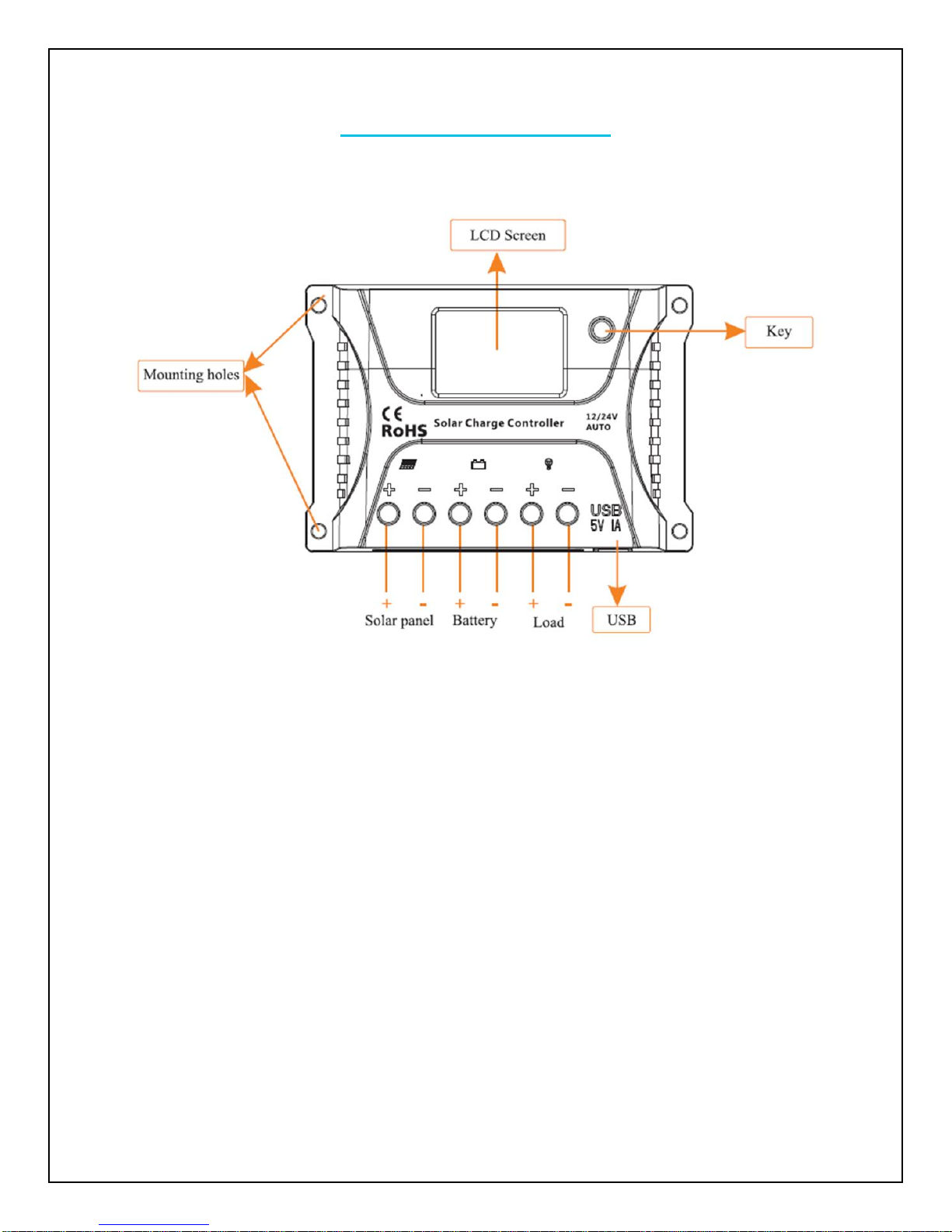
Controller Panel Structure
Page 7

6
Controller Operation
Step 1: Connect the battery. If the connection is correct, the controller screen lights up; otherwise,
check whether the connection is correct.
Step 2: Connect the solar panel. If sunlight is present and strong enough (the solar panel voltage
is greater than battery voltage), the sun icon on the LCD screen is on; otherwise, check whether
the connection is correct.
Step 3: Connect the load. Connect the load leads to the controller's load output terminal, and the
current shall not exceed the controller's rated current.
** The controller has a common positive pole inside. If grounding is needed, ground the
positive pole.
Normal Sequencing Display
The following menus are shown in an automatic cycle on the screen, with an interval of 3s.
Setting Menu on LCD Screen
Long press the red button in any mode to enter the load mode setting interface, and the load
mode begins to flash. Short press the button to adjust the load mode, and long press the button
again to save and exit mode setting or wait for 10s to let the system save and exit automatically.
Battery Voltage
Battery Capacity
Temperature
Error Code
Load Mode
Page 8

7
Five Load Working Modes
1. Pure light control (0): When sunlight disappears, and the light intensity drops to the starting
point, the controller initiates a one-minute delay (settable) to confirm the starting signal, and then
switches on the load for operation. When sunlight emerges, and the light intensity reaches the
starting point, the controller initiates a one-minute delay to confirm the shutting-down signal, and
then shuts down the output to stop the load's operation.
2. Light control + time control (1 to 14): The starting process is the same as pure light control.
After operating for a preset period (settable from 1 to 14 hours), the load stops operation
automatically.
3. Manual mode (15): In this mode, the user can switch the load on or off by the button, no matter
whether it's day or night.
4. Debugging mode (16): In cases of 6V with light signals, the load will be shut off. In cases of 5V
(varies according to the preset light-controlled voltage and system voltage) without light signals,
the load will be switched on. This mode enables fast check of the correctness of system
installation during installation and debugging.
5. Normal on (17): The energized load keeps in output state.
LED Display
Mode
00
Pure light control mode
01-14
Light control + time control (1 to14 hours)
15
Manual mode (default)
16
Debugging mode
17
Always on mode
Load Mode
Mode Flashing
Mode Flashing
Load Mode
Long
press the
button
Short press the
button
Set the needed
mode
Long press the
button to save the
setting
Page 9

8
Manually Switching On/Off Load
When the load mode is set to 15 (manual mode), short press the button (non-setting mode) in any
interface to switch on or off the load.
Note: As load start is a type of soft start, display of the load icon on the LCD screen will be delayed
after the load is switched on.
System Status Icons
Error Code List
Code on LCD Screen
Corresponding Error
E0
No Error
E1
Battery Over-discharged
E2
Battery Overvoltage
E4
Load short circuit
E5
Overload
E6
Controller overheated
System Status Troubleshooting
Description
Troubleshoot
Battery over voltage
Use a multi-meter to check the voltage of the battery. Make
sure the battery voltage is not exceeding the rated
specification of the charge controller. Disconnect battery.
Charge controller does not
charge during daytime when
the sun is shining on the
solar panels.
Confirm that there is a tight and correct connection from the
battery bank to the charge controller and the solar panels to
the charge controller. Use a multi-meter to check if the polarity
of the solar modules has been reversed on the charge
controller’s solar terminals.
Load switched on
Load switched off
Short press the
button
Page 10

9
Everything is connected
correctly, but the LCD on the
controller does not turn on
Check the rated battery voltage. The LCD will not display on
the charge controller unless there is at least 9V coming from
the battery bank.
Maintenance
For best controller performance, it is recommended that these tasks be performed from time to
time.
1. Check wiring going into the charge controller and make sure there is no wire damage or
wear.
2. Tighten all terminals and inspect any loose, broken, or burnt up connections
3. Make sure readings in the LCD and LED are consistent.
Frequently Asked Questions
Q. Can the kit charge two or more 12V batteries connected in parallel?
A. Yes, it’s possible if the batteries have the same type and capacity and are wired in parallel as
a single 12V battery bank.
Q. Is there any risk that the solar kit will over charge my battery?
A. One of the functions of the solar charge controller is to ensure that your battery is not over
charged; therefore there is no risk of overcharge.
Q. Can I extend the battery leads?
A. Yes, it’s possible – please choose the same size of cable for extension. However, there longer
the extension, the greater the line loss. Bigger gauge will be required for longer runs.
Q. Do I need to clean the solar panels?
A. Yes, it is recommended for better performance. Dust and dirt should first be swept off the
panel surface using a soft brush. When the sweeping is complete, use a wet cloth to wipe the
panel surface to remove remaining dirt and grime.
Q. Can rain damage the solar kit?
A. Yes, the charge controller is not waterproof.
Page 11

10
Technical Specifications
Solar Panel Parameters
Description
100 W Parameters
50W Parameters
Maximum Power
100 W
50 W
Open Circuit Voltage (Voc)
23.1 V
23.6 V
Short Circuit Current (Isc)
6.07 A
3.13 A
Maximum Power Voltage (Vmp)
18.3 V
18.3 V
Maximum Power Current (Imp)
5.35 A
2.85 A
Cell Type
Monocrystalline
Monocrystalline
Operating Temperature
−40°F to +185°F
−40°F to +185°F
Folded Size
21.25x21.5x0.35 inches
21.65x11.4x0.42 inches
Net Weight
7.25 lbs
3.97 lbs
Charge Controller Parameters
Electrical Parameters
Model Rating
10A
Normal Battery Voltage
12V/24V
Maximum Solar Voltage(OCV)
55V
Maximum Battery Voltage
35V
Rated Charging Current
10A
Electrical Protection and Feature
Over-temperature
Overload and short circuit protection
Reverse current from battery to solar panel protection at
night
Grounding
Common Positive
Self-consumption
< 12mA
Overvoltage Protection
17.0V; x2/24V
Equalization Voltage
14.6V; x2/24V
Boost Voltage
14.4V; x2/24V
Float Voltage
13.8V; x2/24V
Equalization Charging Time
1H
Boost Charging Time
2H
Temperature Compensation
-3.0mV / °C
Mechanical Parameters
Dimensions
L4.05 x W2.79 x H1.41 inches
Weight
0.22 lbs.
Mounting
Vertical Wall Mounting
Ingress Protection Rating
IP30
Maximum Terminals Wire Size
14AWG
Operating Temperature
-13 ⁰F to +131 ⁰F
Temp. Comp. Range
-4°F ~ 122°F
Page 12

11
Charging Parameters Glossary
Equalization Voltage—equalization voltage is a corrective over-charge of the battery. The user
should consult their battery manufacturer regarding specific battery equalization capacity. This
parameter sets the equalization voltage to set the battery at when it reaches the equalization
state.
Boost Voltage—users should check with their battery manufacturer for proper charging
parameters. In this stage, users set the boost voltage where the battery will reach a voltage
level and remain there until the battery undergoes an absorption stage
Float Voltage—once the charge controller recognizes the set float voltage, it will commence
floating. The battery is supposed to be fully charged in his state, and the charge current is
reduced to maintain battery stability levels.
State of Charge
12 V Battery
Volts per Cell
100%
12.7
2.12
90%
12.5
2.08
80%
12.42
2.07
70%
12.32
2.05
60%
12.20
2.03
50%
12.06
2.01
40%
11.9
1.98
30%
11.75
1.96
20%
11.58
1.93
10%
11.31
1.89
0
10.5
1.75
Page 13

12
Dimensions
10A PWM
Unit: mm
Page 14

13
100 W Suitcase
Unit: mm
50 W Suitcase
Renogy reserves the right to change the contents of this manual without notice.
 Loading...