

Page 1
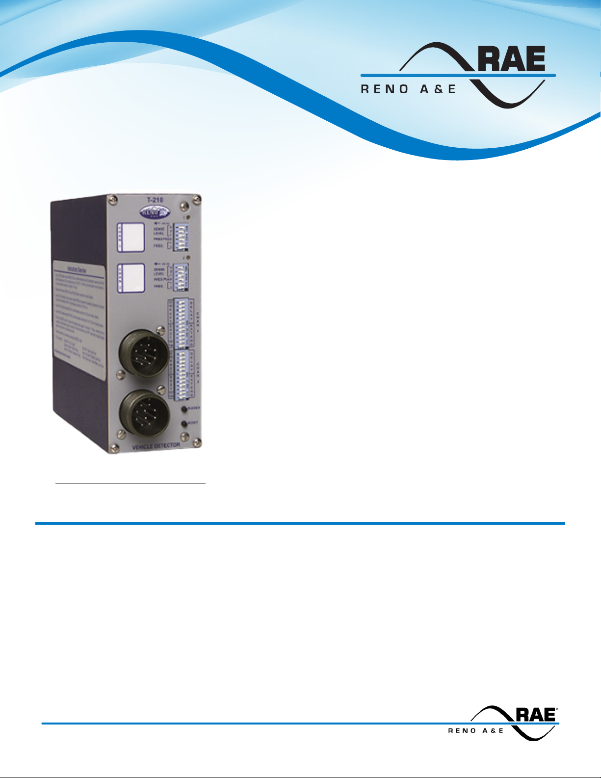
T - 210 Series
Two Channel Shelf Mount Detector
• Meets and exceeds NEMA TS 1 specication.
• Six front panel DIP switches for each channel provide:
• Seven levels of sensitivity plus off.
• Presence or Pulse mode.
• Four loop frequencies.
• Loops are sequentially scanned to eliminate crosstalk.
• Loop Fail Event Monitor remembers and indicates intermittent and
current loop failures.
• Detector is self tuning and provides complete environmental
®
tracking.
• Dual color, high intensity LED:
• Green indicates detect.
• Red indicates loop fail.
• Complete built-in detector integrity test.
• Space provided on front panel to label detector.
• Audible detect signal (buzzer) facilitates loop and/or detector
With Audible Detect Signal
troubleshooting.
• Call Delay and Call Extension timing.
Ordering Information:
Model T-210-R Two channel detector with Relay Outputs, Call Delay, and Call Extension
Model T-210-SS Two channel detector with Solid State Outputs, Call Delay, and Call Extension
The Model T-210 series is designed to meet or exceed NEMA Standards TS 1-1989. Model T-210 Detectors are
two channel, shelf mount type loop detectors with Delay and Extension timing. Individual channel detect and
loop fail indications are provided via two dual color, high intensity LEDs. Available with both Relay and Solid
State outputs, the Model T-210 series offers advanced multiple channel detection capabilities in a compact
package.
3510 E. ATLANTA AVENUE, PHOENIX AZ 85040 +1.480.968.6407 EDITRAFFIC.COM
Page 2
T-210 Series Specications
This is a Performance Specication. It is not intended to be used as Operating Instructions.
Loop Frequency: Each channel has four (4) DIP switch selectable loop frequencies (normally in the
range of 20 to 100 kilohertz) that are a function of the actual loop / lead-in network.
Sensitivity: Seven (7) sensitivity levels (plus off) are available for each channel. The eight settings are
selectable using three (3) front panel mounted DIP switches. Each of the seven sensitivity levels are
binary encoded from 1 to 7 (lowest to highest sensitivity). A setting of 0 turns the channel off. The
sensitivity level selected determines the percentage of negative inductance change of the loop circuit
required for a CALL output signal. See SENSITIVITY, -∆L/L, & RESPONSE TIME table.
Presence / Pulse Mode: Each channel can be independently set to operate in one of two modes by
means of front panel mounted DIP switches.
Presence Mode: Call hold time is a minimum of four minutes regardless of vehicle size, and is typically
one to three hours for an automobile or truck.
Pulse Mode: A pulse of 125 ±10 milliseconds duration is generated for each vehicle entering the loop
detection zone. Each vehicle detected is instantly tuned out if it remains in the loop detection zone
longer than two seconds. This feature allows detection of vehicles subsequently entering the detection
zone. After each vehicle leaves the loop detection zone, the channel resumes full detection sensitivity
within one second. Changing the setting of the Presence / Pulse Mode switch will RESET the channel.
Call Delay: Each channel’s Call Delay is adjustable from 0 to 63 seconds in one-second steps by means
of six (6) front panel mounted DIP switches. Call Delay time starts counting down when a vehicle rst
enters the loop detection zone. If the Delay feature is activated, the output will only be turned on after
the selected delay time has passed with a vehicle continuously present in the loop detection area. If
a vehicle leaves the loop detection area during the delay interval, detection is aborted and the next
vehicle to enter the loop detection area will initiate a new full delay interval. The detector indicates that
a vehicle is being detected but that the outputs are being delayed by ashing the channel’s Detect / Fail
LED (green) at four Hz with a 50% duty cycle.
Call Extension: Each channel’s Call Extension is adjustable from 0 to 15.75 seconds in 1/4-second
steps by means of six (6) front panel mounted DIP switches. Call Extension time starts counting down
when the last vehicle leaves the loop detection zone. In the event a vehicle enters the loop detection
zone before the extension time expires, the detector will return to the detect state (regardless of the
setting of the delay timer) and the extension timer will be reset. When the last vehicle leaves the loop
detection zone, full Extension time is reestablished and the detector begins counting down again. The
detector will indicate that the extension interval is currently timing by ashing the channel’s Detect /
Fail LED (green) at 16 Hz with a 50% duty cycle.
Audible Detect Signal: A front panel mounted push button is used to enable an audible detect signal
that is emitted any time a given channel’s detection zone is occupied.
Detect / Fail Indicator: Each channel has a super bright, high intensity, dual color (Red / Green) LED
that indicates a Call output and/or the status of any current or prior loop fault condition for that channel.
A continuous ON (green) state indicates a CALL output. A continuous ON (red) state indicates that a
current open loop failure condition or an inductance change condition of greater than +25% condition
exists. This indication is also generates a CALL output. A one Hz (red) ash rate indicates that a current
shorted loop failure condition or an inductance change condition of greater than -25% condition exists.
This indication is also generates a CALL output. A ash rate of three 50 millisecond (red) pulses
indicates a prior loop failure condition. A ash rate of three 50 millisecond (red) pulses followed by a
750 millisecond (green) pulse indicates a prior loop failure condition and a current CALL output (detect
state). If the audible detect signal is activated, any detect indication that would normally be displayed
as green will be displayed as orange.
Loop Fail (Event) Monitor: If the total inductance of a channel’s loop input network goes out of the
range specied for the detector, or rapidly changes by more than ±25%, the affected channel will
immediately enter the Fail-Safe mode of operation. Fail-Safe operation generates a continuous call
output in Presence or Pulse mode. The channel’s Detect / Fail LED will provide an indication of the type
of loop failure (see Detect / Fail Indicator, above) and will continue to do so as long as the loop fault
exists. If the loop self-heals, the channel will resume operation in a normal manner, but the Detect / Fail
LED of the channel will begin to ash at a rate of three ashes per second (red) as a means of indicating
a prior Loop Fail condition. The Detect / Fail LED will continue its indication of a prior loop failure until
the detector channel is reset, the detector is reset, or power is removed.
Loop Inductance Range: 20 to 2000 microhenries with a Q factor of 5 or greater.
Loop Feeder Length: Up to 5000 feet (1500m) maximum with proper feeder cable and appropriate
loops.
Loop Input: Transformer isolated. The minimum capacitance added by the detector is 0.068 microfarad.
Scanning: The loop(s) connected to each detector channel are activated alternately to minimize
crosstalk between adjacent loops connected to the same detector.
Lightning Protection: The detector can tolerate, without damage, a 10 microfarad capacitor charged
to 2,000 volts being discharged directly into the loop input terminals, or a 10 microfarad capacitor
charged to 2,000 volts being discharged between either loop terminal and earth (chassis) ground.
Detector Reset: Changing the position of either channel’s DIP switches (except the Frequency
switches or Call Delay / Call Extension switches) will reset that detector channel. Pressing the front
panel mounted reset switch will reset the detector. Reapplication of power after a power loss will
also cause the detector to reset. After changing either channel’s Frequency selection switches (DIP
switches 1 & 2), the channel will require a reset.
Phase Green Inputs: Also known as Delay Inhibit inputs. Meets or exceeds NEMA TS 1 requirements.
The application of an ON state voltage (75 to 130 VAC) to the Phase Green Input pin (Pin J) of the
Channel 1 or Channel 2 connector will cause that channel’s delay timer to abort its delay timing function.
Solid State Outputs: Optically isolated. 30 VDC max. collector (drain) to emitter (source). 100 mA max.
saturation current. 2 VDC max. transistor saturation voltage. The output is protected with a 33-volt
Zener diode connected between the collector (drain) and emitter (source).
Relay Outputs: The relay contacts are rated for 6 Amps max., 150 VDC max., and 180 Watts max.
switched power.
Response Time: The response time of any channel is 65 ± 25 milliseconds regardless of the
sensitivity level setting. See SENSITIVITY, - ∆L/L, & RESPONSE TIME table.
Self Tuning: The detector automatically self tunes and is operational within two seconds after
application of power or after being reset. Full sensitivit y and hold time requires 30 seconds of
operation.
Environmental & Tracking: The detector is fully self-compensating for environmental changes and
loop drift over the full temperature range and the entire loop inductance range.
Grounded Loop Operation: The loop isolation transformer allows operation with poor quality
loops (which may include one short to ground at a single point).
Detect Outputs: A detection output (CALL) is indicated by a closed relay contact (Relay output)
or a conducting state (Solid State output). A channel’s output defaults to a CALL state for any loop
failure condition on that channel or upon loss of power.
Test Mode: A PCB mounted jumper enables Test Mode. Test Mode provides a means of verifying
proper operation of the detector’s controls and indicators (switches and LEDs). Each channel’s
loop oscillator circuit is also checked to verify the correct frequency in each of the four frequency
settings. The frequency portion of testing requires that each channel be connected to a 100
microhenry loop; if other inductance values are used, the frequency test results will be invalid.
Weight: 27 oz (765.5 gm).
Size: 6.45 inches (16.38 cm) high x 2.50 inches (6.35 cm) wide x 6.35 inches (16.13 cm) deep
(excluding connector). Connector adds .675 inches (1.71 cm) to depth measurement.
Operating Temperature: -40ºF to +180ºF (-40ºC to +82ºC).
Circuit Board: Printed circuit boards are 0.062 inch thick FR4 material with 2 oz. copper on
both sides and plated through holes. Circuit boards and components are conformal coated with
polyurethane.
Connectors: Two (2) MS 3102A-18-1P 10 pin male. See PIN ASSIGNMENTS table.
Power: 89 to 135 VAC, 50/60 Hz, 6 Watts max.
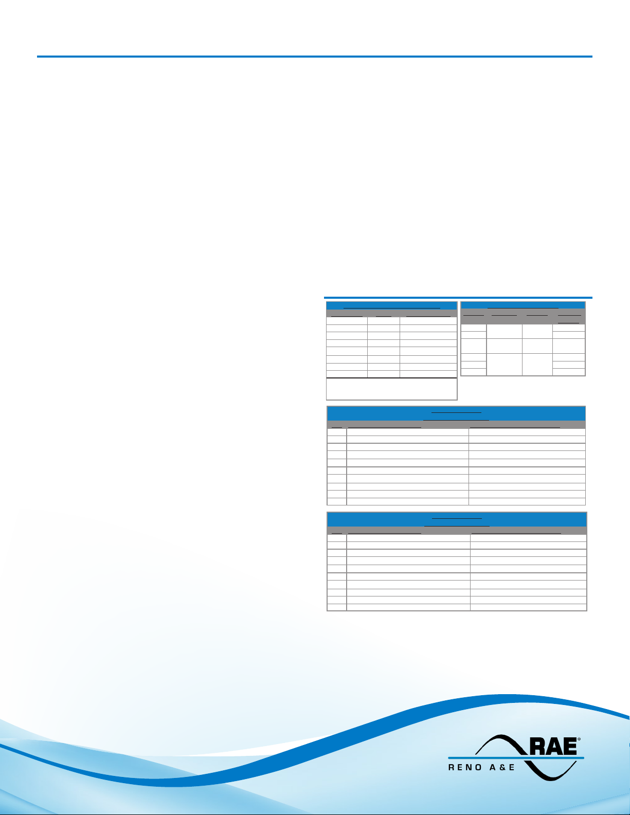
Sensitivity, -∆L/L, Response Time
Sensitivity -∆L/L Response Time
0 OFF N/A
1 0.64% 65 +/- 25 ms
2 0.32% 65 +/- 25 ms
3 0.16% 65 +/- 25 ms
4 0.08% 65 +/- 25 ms
5 0.04% 65 +/- 25 ms
6* 0.02%* 65 +/- 25 ms*
7 0.01% 65 +/- 25 ms
* Denotes Factory Default
Notes: Changing a sensitivity switch will
RESET the detector.
PIN Assignments
PIN Function (Relay Outputs) Function (Solid State Outputs)
A Power, Neutral, 120 VAC Power, Neutral, 120 VAC
B Channel 1 Output, Relay Common Channel 1 Output, Emitter (Source)
C Power, Line, 120 VAC Power, Line, 120 VAC
D Channel 1 Loop Input Channel 1 Loop Input
E Channel 1 Loop Input Channel 1 Loop Input
F Channel 1 Output, Relay N.O. Channel 1 Output, Collector (Drain)
G Channel 1 Output, Relay N.C. No Connection
H Chassis Ground Chassis Ground
I No Connection No Connection
J Channel 1 Phase Green Input Channel 1 Phase Green Input
PIN Function (Relay Outputs) Function (Solid State Outputs)
A No Connection No Connection
B Channel 2 Output, Relay Common Channel 2 Output, Emitter (Source)
C No Connection No Connection
D Channel 2 Loop Input Channel 2 Loop Input
E Channel 2 Loop Input Channel 2 Loop Input
F Channel 2 Output, Relay N.O. Channel 2 Output, Collector (Drain)
G Channel 2 Output, Relay N.C. No Connection
H Chassis Ground Chassis Ground
I No Connection No Connection
J Channel 2 Phase Green Input Channel 2 Phase Green Input
(Channel 1 Connector)
PIN Assignments
(Channel 2 Connector)
Factory Default Settings
Switch Function Setting Factory
1 Frequency 0 OFF
2 OFF
3 Presence /
4
5 ON
Sensitivity 6
6 ON
Pulse
Presence ON
Default
OFF
Model T-210 (551-2005-00) 03/23/2020
© COPYRIGHT 2020. Eberle Design, Inc. All Rights Reserved.
 Loading...