

Page 1
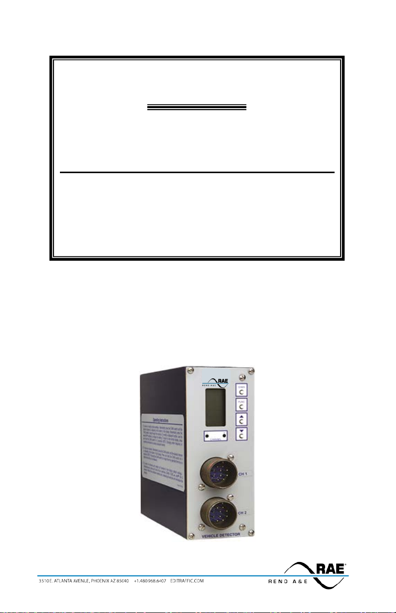
Model S-1300 Series
MODEL S-1300
Loop Detector
Operations Manual
Two Channel Menu Driven Programmable Inductive Loop
Detector
Built-in Loop Analyzer for Each Channel
This manual contains technical in formation for the
Model S-1300 Loop Detector
pn 889-1908-00 Revision: April 2020
Page 2

Page 3

THE FOLLOWING PRODUCT WAS DESIGNED, INSPECTED , TESTED AND
MANUFACTURED IN THE USA BY EBERLE DESIGN, INC. IN PHOENIX, ARIZONA.
INFORMATION CONTAINED HEREIN IS PROPR IETARY TECHNICAL INFORMATION OF
EBERLE DESIGN, INC. PUBLICATION, REPRODUCTION OR USE IN WHOLE OR PART IS
NOT PERMITTED EXCEPT UNDER TERMS AGREED UPON IN WRITING. ALL
REGISTERED TRADEMARKS OF EBERLE DESIGN INC. ARE UNDER
IT IS AN EBERLE DESIGN, INC. RECOMMENDATION THAT EACH UNIT BE TESTED
AT LEAST ANNUALLY TO ENSURE COMPLIANCE WITH FACTO RY
SPECIFICATIONS AND MEETS PROPER OPERATIONAL STANDARDS. THE
RESULTS OF THIS TESTING WILL BE DOCU M EN T ED .
© COPYRIGHT
MAINTENANCE NOTE
Page 4

Page 5

Model S-1300 Operations Manual
Table of Contents
Section 1 General Description .......................................................................................................... 1
Section 2 General Characteristics .................................................................................................... 2
2.1 Loop Frequency ..................................................................................................................... 2
2.2 Sensitivity .............................................................................................................................. 2
2.3 Presence / Pulse ..................................................................................................................... 2
2.4 Call Delay .............................................................................................................................. 2
2.5 Call Exte ns ion ........................................................................................................................ 2
2.6 Max Presence Timer .............................................................................................................. 2
2.7 End-Of-Green (EOG) ............................................................................................................. 3
2.8 Option 1: Loop Inductance Display ....................................................................................... 3
2.9 Option 2: Loop Inductance -∆L/ L Display ............................................................................. 3
2.10 Option 3: Call Ext ension Control ......................................................................................... 3
2.11 Option 4: Noise Filter Disable ............................................................................................. 3
2.12 Option 5: Phase Green Loop Compensation ........................................................................ 4
2.13 Option 9: Third Car Passage ................................................................................................ 4
2.14 Option 10: Direc tional Logic ............................................................................................... 4
2.15 Option 11, Audible Detect Signal ........................................................................................ 5
2.16 Option 12: Detector Disconnect ........................................................................................... 5
2.17 Option 13: True Presence ..................................................................................................... 6
2.18 Option 14: Sensitivity Boost ................................................................................................ 6
Section 3 Specifications ..................................................................................................................... 7
3.1 Physical .................................................................................................................................. 7
3.2 Electrical ................................................................................................................................ 7
3.3 Operational ............................................................................................................................ 7
3.4 Table: Sensitivity, -∆L/L, and Response Time ....................................................................... 8
3.5 Table: Default Settings ........................................................................................................... 8
3.6 Table: Pin Assignments ......................................................................................................... 9
Section 4 User Interface .................................................................................................................. 10
Section 5 Installation and Set-Up ................................................................................................... 11
5.1 Program Mode Display Screens ........................................................................................... 11
5.2 Normal Mode Display Screens ............................................................................................ 15
5.3 Loop Fail Indications ........................................................................................................... 17
5.4 Setting Sensitivity using the Bargraph ................................................................................. 18
5.5 Setting Sensitivity for Motorcycle Detection using the Bargraph ........................................ 19
5.6 Full Restore to Factory Default Settings .............................................................................. 19
5.7 Display Test ......................................................................................................................... 19
Section 6 Block Diagram ................................................................................................................ 20
Section 7 The o ry of Operation ....................................................................................................... 21
Section 8 Maintenance and Troubleshooting ................................................................................ 22
8.1 Troubleshooting Power Problems ........................................................................................ 22
8.2 Troubleshooting Initialization Problems .............................................................................. 22
8.3 Troubleshooting Loop Fail Problems ................................................................................... 23
8.4 Troubleshooting Intermittent Loop Fail Problems ............................................................... 24
8.5 Troubleshooting Intermittent Detector Lock-Ups ................................................................ 24
8.6 Troubleshooting Delay Problems ......................................................................................... 25
8.7 Things to Know About Loops .............................................................................................. 25
Page 6

Page 7

Section 1 General Description
This Operation Manual was written for people installing, operat ing, and maintaining Reno A & E Model S-1300
Series inductive loop vehicle detectors. The Model S-1300 is a two channel, shelf mount type, inductive loop
vehicle detector designed to meet or exceed NEMA Standards TS 1-1989.
The Model S-1300 incorporates a microcontroller that monitors and process es signals from two separate
loop / lead-in circuits and two Phase Green Inp uts. The microcontroller uses these inputs to determine
how to c ontro l the detec tor o utp uts. A Liqu id Crysta l Disp lay ( LCD), two light e mitt ing diodes (LEDs),
and four front panel pushbuttons are used to display and program all detector functions. Several
diagnostic modes are available to aid technicians and service personnel in troubleshooting detection
problems.
The use of a LCD is what distinguishes this detector from that of other manufacturers. It allows more informat ion,
never before available, to be displa yed to t he use r during normal operation of the detector. The LCD makes it easy
to view and adjust all programmable detector opt ions and settings. It is no longer necessary to check o r change
detector settings with DIP sw itches. An eight-segment bargraph at the top of the L CD can be used to provide a
graphical representation of the relative change of inductance as seen by the detector at the current sensitivity level.
The bargraph automatically takes into account loop size, loop inductance, nu mber of loops, number of turns, loop
geometry, lead-in lengt h, e tc. The bargraph functions as a sliding scale that relates to the programmed Sensitivity
Level. The first (left-most) bargraph segment represents the minimum inductance change necessary for the
detector to output a call at the currently selected sensitivity leve l. Larger i nducta nce chan ges will i ndicate more
segments. Each additional segment indicates that the next sensitivity level has also been met or exceeded. When
used in t his manne r, the bar graph prov ides an ind ication of whether t he sensiti vity is set too high or too low,
facilitating the ideal setting of the se ns itivity level.
All programmed settings are stored in non-volatile memory and can only be changed by programming new
settings. Loss of power or a de tector reset will not change any of t he p rogrammed settings. If a loop failure
occurs, the LCD will display the type of lo op failure as L lo (for -25% change or shorted loop conditions) or L hi
(for +25% change or open loop c onditions). Each loop failure is counte d and accumulated in the Loop Failure
Memory. The number of loop failures since the last detector reset or power interruption is very useful information
to have available during analysis of intermittent loop operation.
The Model S-1300 Series detector is a scanning detector. The scanning operation sequentially activates t he ON
and OFF cycle of each channel’s oscillator. Since only one channel’s loop(s) is (are) active at a given time,
crosstalk between adjacent loops connected to the same scanning detector is mini mize d. The Model S-1300
Series’ unique scanning process a lso disconnects the capac itors and dampe ns the oscillator during t he OFF cycle.
This eliminates oscillation past the OFF po int (ringing or dec ay) every time the loop circuit is sca nned, which can
result in crosstalk. W hen operating in the Program Mode, t he Model S-1300 Series disp lays t he rea l time loop
frequency reading for each channel. T he eight frequency settings ca n be incremented or decremented to p rovide
precise frequency readings, removing any guesswork when changing frequency settings to eli minate crosstalk.
NOTE: Adjacent loops connected to different c hannels of a non-scanning dete ctor or d ifferent scanning dete ctors
should be set to different frequencies with maximum separation.
The Reno A & E Model S-1300 Series utilizes the first major innovatio n in inductive loop detectors since the
introduction of digital detecto rs. The programming of all of the detector’s para meters with four normally open
pushbutton switches not o nly simplifies setup by removing binary coded DIP switches, but also increases the
reliability of the detector by eliminating the dependence on switch contacts during normal operation. The detailed
descriptions displayed on the LCD eliminate the interpretation of numerous LED flash rates to determine the
detector status. In addition, the Model S-1300 offers t he versatility of softwa re control. Special funct ions are
possible with a simple change of the s ocket-mounted microprocessor. Special functions are de fined as unique
optio ns (e. g. Opt ion 6, Option 12, etc. ). Special opt ion functions are activated through t he use of the LCD menu
option programming.
The Model S-1300 Series is comprised of the following detectors:
S-1300-R For NEMA TS 1-1989 applications calling for a two channel, 120 volt AC,
S-1300-SS For NEMA TS 1-1989 applications calling for a two channel, 120 volt AC,
S-1300-R-12D For NEMA TS 1-1989 applicat ions calling for a two channel, 12 volt DC,
S-1300-SS-12D For NEMA TS 1-1989 applicat ions calling for a two channel, 12 volt DC,
shelf mount detector with relay outputs and an audible detect signal
(buzzer).
shelf mount detector with so lid state outputs and an audible detect signa l
(buzzer).
shelf mount detector with relay outputs and an audible detect signal
(buzzer).
shelf mount detector with so lid state outputs and an audible detect signa l
(buzzer).
889-1908-00 Model S-1300 Operations Manual Rev Apr 2020 Page 1 of 25
Page 8

Section 2 General Characteristics
2.1 LOOP FREQUENCY
There are eight (8) selectable loop frequency settings (nor mally in the range of 20 to 100 kilohertz) per c hannel.
The actual loop operating frequency is a function of the loop / lead-in network and the components of the loop
oscillator circuit. The d igital display of the actual loop operating frequency for each setting makes it easy to
quickly identify and eliminate crossta lk in the most difficult to configure intersections. The frequency display is
typica lly very stab le when the loop is vacant and veh icles are not passing nearby the loops. If the reading is
varyin g by more than ±1 in the last digit, this is an indication of possible crossta lk betwee n loops.
2.2 SENSITIVITY
There are nine (9) selectable sensitivity levels per channel, plus Continuous-Call and Cha nne l-O f f. T he s ensitiv i t y
levels are designed so that a one level increase actually doubles the sensitivity and a one level decrease halves the
sensitivity. A unique bargraph d isplayed on t he LCD makes it eas y to quickly set sensitivity at t he ideal leve l for
any loop / lead-in network configuration. (See Section 3.4 for actual detection levels at each sensitivity level.)
C
ONTINUOUS-CALL: Whe n se t t o t he Co nt in uo us -Call state , the c hannel ou tput is co ntinuous ly in t he Call state
regardless of t he presence or absence of vehicles o ver the loop. The loop oscillator is d isabled when in the
Continuous-Call state. T his state is indicated b y CALL flashing on the LCD. This option is selected from the
Sensitivity menu in Program Mode and is useful for checking co ntroller response and other troubleshooting
activities.
C
HANNEL-OFF: When s et to the Channel-O ff state, the channel output is cont inuously in the No Call state
regardless of the presence or absence of vehicles over the loop. The loop oscillator is disabled when in the
Channel-Off State. This sta te is indicated by OFF flashing on t he LCD. This option is selected from the
Sensitivity menu in Program Mode and is useful for checking co ntroller response and other troubleshooting
activities.
2.3 PRESENCE / PULSE
One of two mutually exclusive modes of operation for each channel is available. Presence or Pulse mode is
toggled by momentarily pressing e ither the (UP) or (DOWN) button.
P
RESENCE MODE: Provides a call hold time of at least four min utes (regardless of vehicle size) and typically one
to three hours for an automobile or truck.
P
ULSE MODE: An output Pulse of 125 ±10 milliseconds duration is generated for each vehicle entering the loop
detection zone. Each detected vehicle is instantly tuned out if it remains in the loop detection zone longer than
two seconds. This enables detection of subsequent vehicles entering the loop detection zone. After each vehicle
leaves the loop detection zone, the cha nnel resumes full sensitivity within 0.5 seconds.
2.4 CALL DELAY
Each channel’s Call Delay is ad justab le from 0 t o 255 seconds in one-second steps. Call Delay time starts counting
down when a vehicle enters the loop detection zo ne. The remaining Ca ll Delay time i s continuous ly displayed on
the LCD . W he ne ver a P has e Gr ee n I np ut ( C all D e lay O ve rr id e) si gna l (p i n J o f t he M S co nne ct or of c ha nne l 1 or
2) is active, the Call Delay func tion for the channel is aborted and the Call Delay time is forced to zero.
2.5 CALL EXTENSION
Each channel’s Call Extension is adjustable from 0 to 255 sec onds in one-second steps. Extension time sta rts
counting down when the last vehicle clears the loop detection zone. The remaining Call Extension time is
contin uous ly d isp la yed o n the LCD. Any veh icle ente r ing t he lo op de tec tio n zo ne d uri ng t he Ca ll E xtens io n ti me
period causes the channel to return to the Detect state, and later, when the last vehicle clears the loop detection
zone, the full Call Exte nsion time starts counting down again. (See Option 3, Call Extension Contro l, for an
alternate mode of operation for Call E xtension.)
2.6 MAX PRESENCE TIMER
When activated, each channel’s Max Presence timer is adjustable from 1 to 999 seconds in one-second steps. A
setting of OFF turns the Max Presence timer off. The Max Presence function is used to limit presence time, by
automatically resetting the channel. If this function is enabled (ON), the Max Pre sence timer begins counting
down when a call is initiated and t he remaining ti me is continuously displaye d on the LCD. If t he loop becomes
vacant before the Max Presence timer reaches zero, the call is dropped and no automatic reset occurs. If the EndOf-Green (EO G) func tion is no t enab led (O FF) and th e call is s till pre sent when the Max Presence timer reaches
889-1908-00 Model S-1300 Operations Manual Rev Apr 2020 Page 2 of 25
Page 9

zero, the cha nnel then is aut omatically reset. If the EOG functi on is e nabled (ON) and the call is still present w hen
the Max Presence timer reaches zero, the channel enters a Wait state. The Wait state continues until either the loop
becomes vacant or the Phase Green Input signal for a channel (pin J of the MS connector) transitions from green to
not green with the call still present. If the loop becomes vacant first, the call is dropped and no automatic reset
occurs. If the Phase Green Input transitions from green to not green while a cha nne l is in a Wait state, the channel
is automatically reset. The signals on pin J of the MS connectors of channels 1 and 2 are also called Call Delay
Overrides. (See Section 3.2, Phase Green Input specification for voltage levels.)
2.7 END-OF-GREEN (EOG)
Each channel’s EOG setting can be toggled O N or OFF b y moment arily pr essing either the (UP) or (DOWN)
button. The EOG function is used to synchronize resetting of a detector with the termination of t he associated
phase green. The assumption is that t his is the sa fest point in t ime to reset the c hannel. T his assumption is based
on the premise that at the termination of t he as s ociated p hase green, traffic should be moving, and therefore, a reset
would not result in the loss of a ca ll when traffic comes to rest over the loop(s). The EOG function is only
available when the Max Presence function is set between 1 and 999 seconds. It is not available when the Max
Presence function is OFF. When the EOG function is enab led (ON), the channel will automatically be reset at the
same time the Phase Green Input signal (pin J of the MS connector) transitions from the ON state to the OFF state,
if the Max Presence Time has counted down to zero and is resting in the wait state. The signa ls on pin J of the MS
connectors of channels 1 and 2 are also called Call Delay Override. (See Section 3.2, Phase Green Input
specifications for voltage levels.)
2.8 OPTION 1: LOOP INDUCTANCE DISPLAY
Each cha n ne l’s Loo p Induc ta nce D isp la y se tt in g ca n be to gg led O N o r O FF b y mome nt ar il y pre ss i ng e it he r the
(UP) or (DO W N ) b u t to n. W hen this option is e na b le d (ON), t he LCD d is p lays the to t al lo o p i nd uc t a nc e (a c t ua l
loop inductance plus actual lead-in inductanc e) in micro henrie s for lo op ind uctance values in the r ange of 2 0 to
2500 microhenries. By recording the inductance of the loop / lead-in circuit when it is first insta lled, the actual
inductance can be compared to the expected ind uctance to help identify defective loop / lead -in circuits. Loop /
lead-in inductance can be easily estimated using the simple formulas included in Section 8.7 of this manual.
NOTE: Enabling this option activates i t for both channe ls. Th is option is automat ica lly disabled 15 m inutes after
activation or on loss of power.
2.9 OPTION 2: LOOP INDUCTANCE -∆L/L DISPLAY
Each cha n ne l’s Loo p I nd uct a nce -∆L/L Display sett ing can be toggled ON or OFF by momentarily press ing either
the (UP) or (DOWN ) button. When this o ption is enab led (ON), the LCD dis plays the per centage of
induct ance change (-∆L/L value) during the Call state. To fac ilitate the viewing of the maximum amount of
change in the -∆L/L value w hile traffic is in motion over the detection zone, the channel holds the peak -∆L/L
value for a period of two seconds. NOTE: Enabling t his option activates it for both channels. This option is
automatically disabled 15 minutes after activation or on loss of power.
2.10 OPTION 3: CA L L EXTENSION CONTROL
Each cha nnel’ s Cal l Exte nsion C ontro l set ting ca n be to ggled O N or OF F by mo mentar ily pre ssin g eithe r the
(UP) or (DO WN ) b ut to n. W he n t h is o pt io n is e nab led (O N) , t he c ha n nel w ill e x tend ca l ls f or t he pr o gra mme d
extens ion t ime only whe n the Phase Green Input signal (pin J of the MS connector) is active. When this option is
OFF, the channel extends ALL calls for the programmed extension time. The signals on pin J of the MS
connectors of channels 1 and 2 are also called Call Delay Overrides. (See Section 3.2, Phase Green Input
specifications for voltage levels.)
2.11 OPTION 4: NOISE FILTER DISABLE
The detector’s Noise Filter Disable setting can be toggled ON or OFF by momentarily pressing either the (UP)
or ( DO WN ) b utt o n. W he n Op t io n 4 is e nab led (ON), internal noise filtering is disabled thus provid ing a faster
response time. When this option is O FF, internal noise filtering is utilized. W hen the detector is used in speed
and/or occupancy applications, the noise filter should be disabled (i.e. Option 4 ON) to provide the most accurate
data possible. It is recommended t hat this option not be activated. The factory default setting o f OFF provides
stable operation in high crosstalk e nvironments. NOTE: Enabling this option activates it for both channels.
Changing the setting of this feature will reset both detector channels.
The Loop Fail Count is not reset when the setting of Option 4 is changed. Also, changing the setting of Option 4
will not cause the prior Loop Fail indication to cease (see Section 5.3, Loop Fail Indications).
889-1908-00 Model S-1300 Operations Manual Rev Apr 2020 Page 3 of 25
Page 10
Loop B
Loop A
2.12 OPTION 5: PHASE GREEN LOOP COMPENSATION
Each channel’s Phase Green Loop Co mpensation setting can be toggled ON or OFF by mo mentarily pressing
either the (UP) o r (DOWN) bu t ton. When Op t io n 5 is e na b le d ( O N) , no rmal loop compe nsation is used until
the Phase Green Input signal (pin J of the MS connector) becomes active (low). Once the Phase Gr een Input sign al
is active (high), the channel desensitizes the loop. Maximum desensitization is 0.05% (-∆L/L). This
desensitization tunes out small changes, such as adjacent lane pickup, therefore minimizing the chance of max
timing an empty lane. Note: A small motorcycle may also be tuned out in a short period of time following the star t
of Phase Green. This option is useful in minimizing false detec tion resulting from adjacent lane pickup when a
channel must be run with a high sensitivity setting. When Option 5 is not enabled (OFF), normal loop
compensation is used.
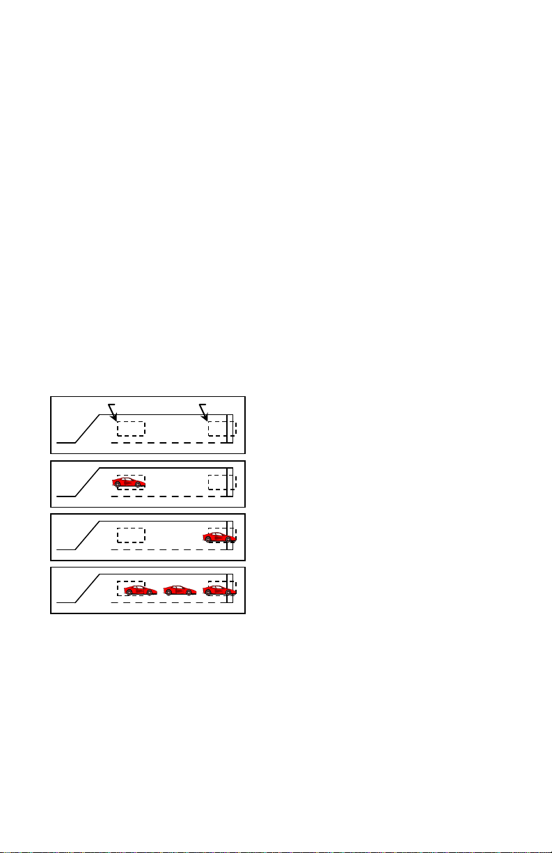
2.13 OPTION 9: THIRD CAR PASSAGE
Each channel’s Third Car Passage setting can be toggled O N or O FF b y momentarily pressing either the (UP) or
(DO WN ) b ut to n. O p tio n 9 is a p a ire d cha nne l opt io n. Th is me ans t hat it ta ke s t w o c ha nne ls to imp le me nt the
feature. Therefore, when this option is toggled ON or OFF in one channel, its paired channe l is also set to the same
state. In the Model S-1300, Channel 1 is paired with Channel 2. NOTE: Option 9 is mut ually exclusive with
Optio n 10. Turning ON one option will automatically turn OFF the other option.
When Op t ion 9 is e nab led (ON ) , t he o utp u t o f the tw o pa ir ed c ha n ne ls a re log ic a lly AND ed t o get he r. Th is mea ns
that while the loops for both of the paired channels are occ upied, a call will be output on both channe ls. While
only o ne c han ne l is oc cupied, or neither channel is occupied, a c all will not be output for either channel. The first
channel with detection will enter a pend ing state w hile wait ing for detect ion on the ot her pa ired cha nnel. While in
the pending state, the LCD will show Pnd on the display.
This feature is intended to be used in Pro tected / Permissive left turn situations. The expected ins tallation is a stop
bar loop for the left turn lane connected to one c hanne l, a queue detect ion loop (with a s mall amount o f delay ti me
programmed) for the left turn lane connected to the other channel, and the output of eithe r channel conne cted to the
Vehicle Call input for the protected movement of the traffic controller.
Basic Installation - Loop A is the Queue Detec tion lo op and
Loop B is the Stop Bar loop.
Car enters Loop A - No ca ll is o utp ut.
Car proceeds to Loop B - No call is output.
Addit io na l c ars ente r t he left tur n lane - When the bac k o f t he
queue reaches Loop A while a car is still over Loop B, a call
will be output.
When T hird Car P assage is turned o n, as the f irst vehi cle enter s the lef t turn la ne it will d rive ove r the queue
detection loop. Since there is no vehic le over the stop bar loop, there is no call output genera ted. The vehicle
advances to the stop bar loop. Still, no output is generated because there is no vehicle over the queue detection
loop. If the vehicle traffic in the left turn lane backs up to the queue detection loop, then the stop bar loop and the
queue detection loop will both be occupied at the same time. This will cause the detector to generate a ca ll to t he
traffic controller to service the protected movement for the left turn. This should help clear the que ue of vehicles
in the left turn lane. The spacing between the stop bar loop and the queue detection loop controls the size of the
queue needed to generate a call to the protected movement of the controller. The delay time on the Queue
Detection loop should be sufficiently long that vehic les driving over this loop to enter the queue do not generate a
call.
2.14 OPTION 10: DIRECTIONAL LOGIC
Each channel’s Directional Logic setting can be toggled ON or OFF by momentarily pressing either t he (UP) or
(DOWN) button. Option 10 is a paired c hannel option. This means that it takes two channe ls to implement t he
feature. Therefore, when this option is toggled ON or OFF in one channel, its paired channe l is a lso set to the sa me
889-1908-00 Model S-1300 Operations Manual Rev Apr 2020 Page 4 of 25
Page 11

Loop B
Loop A
Basic Ins tallat ion
Car enters Loop A - No call is output
Car enters Loop B - No c all is
Car proceeds to Loop B
Call is output o n C hannel B
Car proceeds to Loop A
Call is output o n C hannel A
state. In the Model S-1300, Cha nnel 1 is pair ed wit h Cha nnel 2. NOTE: Op tion 1 0 is mut ually e xclus ive w ith
Optio n 9. Turni ng ON one o ption will auto matica lly turn O F F the other option.
When Option 10 is enabled (ON), directional logic is enabled. Directional logic starts with a detection on one
channel. This channel will go into the pending state, display Pnd on the LC D , a nd N O T output a c a l l. W hen both
of the paired channels have dete ction, the last channel to have detection will output a call until the detection for the
last c ha n ne l e nd s , e ve n if t h e d e te c t ion ends fo r t he fi rs t c hannel. None of t he t i mi n g f un c t io ns of the f ir s t channe l
with a detection will ti me (Delay, Extens ion, Max Presence, a nd Detector Disconnect) a nd the first channel w ill
always operate in the Presence Mode regardless of the programming of the channel.
This feature is intended to be used in parking lot applicatio ns where vehicles can e nter or exit from the sa me lane,
freewa y ra mp s for wro ng w a y de tec t ion, a nd le ft t urn lane s whe re ot her mo ve men ts in t he inte rs ec ti o n te nd t o cl ip
the detection zone of the left turn lane. The expected installation is two loops, one after the other in the same lane,
spaced anywhere from slightly overlapping to 6 feet apar t. NOTE: Contact a Field Engineer at Reno A & E
regarding proper loop configurations and spacing for specific applications.
When Directional Detect ion is turned on, a vehicle entering the first loop will cause that channel to enter t he
pending state. As the vehicle enters the second loop w hile still occupying the first loop, the second channel will
enter the Call state while the first c hanne l remains in t he pending s tate. A call is never outp ut on the first c hannel
with a detection. Under normal conditions both outputs can never be on at the same time. However, if one of the
loops fail, both outputs will come on a nd stay on until the failure is corrected.
2.15 OPTION 11, AUDIBLE DETECT SIGNA L
Each channel’s, Audible Detect Signal setting ca n be toggled ON or OFF by mo mentarily pressing either t he
(UP) or (DOWN) butto n. Only one channel can be turned ON at a time. Turning this option ON for one
channe l automatically t u r ns it O F F fo r t he o t he r channe l. W hen this o p t io n is ena b le d (ON), a n audible signal w i l l
be activated whenever the detection zone for the selected channel is occupied. The audible signal indicates actual
occupancy of the loop detection zone. Timing a nd disconnect functio ns have no e ffect on t he audible s ignal. T his
feature allows a technician to watch the det ection zone on the street and confirm correct detector operation without
having to look at the detector display as well. NOTE: This option is automatical ly disabled 15 minutes after
activation or on loss of power.
2.16 OPTION 12: DETECTOR DISCONNECT
Each channel’s Detector Disconnect se tting can be toggled ON o r OFF and the Extension t imer toggled between
ON and OFF by momenta r il y pr es sing ei t h er t he (UP) or (DOWN) button. The Detector Disconnect feature
requires that the Phase Green Input for the channel be connected to the proper controller phase. When the Phase
Green I nput is n ot a cti ve (low), the cha nne l s hal l oper ate nor ma lly. W hen t he P has e Gre en I np ut is active (high),
the extension timer will start to count down at the end of each detection. If this timer reaches zero before the next
detection, this channel will no longer output a call until the Phase Green Input is not active. Since t he extension
timer is used as a disconnect timer while in this mode, two different disconnect types are available:
Optio n 12.1 OF F : Extension timi ng stil l o ccurs and the e xt ension timer is also the discon nect timer duri ng phase
green. This will cause the call output to remain in the Ca ll state until disconnect occurs. Th is may allow the
user to use gap times appropriate for the advance loops without considering the effects on the stop bar loops.
Option 12.1 ON: Extension timing is disabled and the extension timer is used a s the disconnect timer. This will
cause the call output to follow the occupation of the loop detection zone until disconnect occurs.
This feature is intended to be used in applications where a loop at the stop ba r is not needed after any waiting
queue in the associated traffic lane is movi ng during t he green p hase. The e xpected installatio n is a sto p bar loop
889-1908-00 Model S-1300 Operations Manual Rev Apr 2020 Page 5 of 25
Page 12

Sensitivity Boost Setting
14.0
14.1
14.2
14.3
14.4
Increase in Sensitivity Level(s)
0 1 2 3 4
Detection Zone
Phase Green
Output w/ 12.1 Off
Output w/ 12.1 On
This example assumes an extension time of 2 seconds. The dott ed lines show where disconnect would occur.
Seconds 0 5 10 15 20 25 30 35 40 45 50 55
(typically a 20΄ to 30΄ long detection zone) and an advance detection loop (typically a 6΄ long detection zone) for a
single traffic lane. This feature provides a means for keeping the stop bar loop from placing calls to the traffic
controller after the stop bar loop has served its intended purpose during the beginning period of the associated
Phase Green is the state of the light (actual Phase Green Input is i nv er ted).
green phase. The channel connected to the stop bar loop would have the Detector Disconnect feature turned ON
and have a programmed extension time that functions as the disconnect time. The channel connected to the
advance detection loop would be programmed as normal.
When the Detector Disconnect feature is turned ON and the signal is not green, the channel outputs calls to the
traffic contr oller as us ual. When the signal t urns green, vehicles begin to move and eve ntually the stop bar
detection zone is cleared. At the time that the stop bar detection zone is cleared the disconnect timer begins to
count down. If another vehic le enters the stop bar detection zone before the disconnect timer reaches zero, the
channel outputs the new call to the traffic controller and the disconnect t imer is reset to its initial value. Once the
stop bar detection zone remains clear for a time eq ual to the programmed disconnect time, the detector channel is
disabled and will not generate any further calls to the traffic controller until after the green has terminated. When
the stop bar detection loop is disabled, the green phase can only be extended by vehicles detected by the advance
detection loop. NOTE: The dis connect timer will always time an initial gap each ti me that the p hase tur ns gree n.
If Option 12.1 is OFF, the channel will generate an output for the specified extension time at the start of each
green phase.
2.17 OPTION 13: TRUE PRESENCE
TRUE PRESENCE can be set from 13.0 to 13.5 by press ing the (UP) or (DOWN) pushbutton. When Option
13 is OFF (13.0), the detector operates in the normal PRESENCE mode. When this option is set to 13.1 thro ugh
13.5, TRUE PRESENCE is ON. W hen Option 13 is ON, TRUE PRESENCE will hold the Call as long as the
vehicle is present and power is not removed or the detector reset. TRUE PRESENCE time applies only for normal
size automobiles and trucks and for normal size loops (approximately 12 ft
PRESENCE operation is required, use a setting of 13.1. Contact Re no A & E Technical Suppor t for advice on
applications using loops larger than 120 ft
2
and/or TRUE PRESENCE settings 13.2 to 13.5.
2
- 120 ft2). NOTE: If TRUE
2.18 OPTION 14: SENSITIVITY BOOST
SENSITIVITY BOOST can be set from 14.0 to 14.4 by pressing the (UP) or (DOWN ) pus hbut ton. When
Option 14 is set to 14.0, SENSITIVITY BOOST is turned O FF. When this option is set to 14.1 through 14.4,
SENSITIVITY BOOST is ON. SENSITIVITY BOOST increases the sensitivity of the detector once it has
detected an object. When setting this option, the digit to the right of the dec imal point indicates the number o f
sensitivity levels that the sensitivity will increase after a detection has occurred.
NOTE: The maximum sensitivity level that can be achieved with or without b oost is sensitivity level 9. If a
detector channel is set to sensitivity level 9, the maximum boos t setting attainable is 14.0, i.e. no boost. If a
detector channel is set to sens itiv ity le vel 8, the m aximum boos t s etting at tainable is 14.1, i.e. one (1) level of boost.
If a detector channel is set to sensitivity level 7, the maximum boost setting attainable is 14.2, i.e . two (2) levels of
boost. If a detector channel is set to sensitivity level 6, the maximum boost setting attainable is 14.3, i.e. thr ee (3)
levels of boost. If a detector channel is set to sensitivity level 5, 4, 3, 2, or 1, the maximum boost setting attainable
is 14.4, i.e. four (4) levels of boost.
889-1908-00 Model S-1300 Operations Manual Rev Apr 2020 Page 6 of 25
Page 13

Section 3 Specifications
3.1 PHYSICAL
WEIGHT: 34 oz. (963.9 gm).
S
IZE: 6.45 inches (16.38 cm) high x 2.50 inches (6.35 cm) wide x 6.35 inches (16.13 c m) deep (excluding
connectors). Connectors add .675 inch (1.71 cm) to depth measurement.
O
PERATING TEMPERATURE: -40° F to +180° F (-40° C to +82° C).
C
IRCUIT BOARD: Printed circuit boards are 0.062 inch thick FR4 material with 2 oz. copper on both sides and
plated through holes. Circuit board and components are conformal coated with polyur ethane.
C
ONNECTOR: Two (2) MS3102A-18-1P. See Section 3.6 for pin assignments.
3.2 ELECTRICAL
POWER: 89 to 135 VAC, 50/60 Hz, 6 Watts maximum (120 volt AC models). 9.6 to 14.4 VDC, 250 mA
maximum, 3.8 Watts maximum (12 volt DC models).
LOOP INDUCTANCE RANGE: 20 to 2500 microhenries w ith a Q factor o f 5 or grea ter.
L
OOP INPUTS: Transformer isolated. The minimum capacitance added is 0.068 microfarad.
L
IGHTNING PROTECTION: Meets and/or exceeds all applicable NEMA TS 1-1989 specifications for transient
voltage protection.
R
ESET: M eets and/o r e xceeds NEM A TS 1-1989 detector specifications. The detec tor can be reset by removing
and reapplying power or by changing the setting of Option 4 (Noise Filter Disab le). Each detector channel can be
independently reset by pressing the CHAN button until the desired cha nnel is selected, then pressing and ho lding
the CHA N b ut t o n fo r t hr e e se c o nd s . A ls o, c ha n gi n g either the sensitivit y or loop fr e q uency o f a channe l will res e t
that channel.
P
HASE GREEN INPUTS: Also known as Call Delay Overrides. Meets and/or exceeds all NEMA TS 1-1989
requirements. Application of a high state voltage (89 to 135 VAC) to pin J of the MS connector of channel 1 or 2
causes the delay timer for the channel to ab ort the delay t i ming function a nd also pro vides control for Phase Gree n
Loop Co mpensat ion, Max P resence T iming (E nd-of-Green), Extension Timing, and Detector Dis connect, if the
features are programmed.
R
ELAY RATING: The relay contacts are rated for 6 Amps maximum, 150 VDC maximum, and 180 Watts maximum
switched power.
S
OLID STATE OUTPUT RATING: Optically isolated. 30 VD C maximum collector (drain) to e mitter (source). 100
mA maximum saturation curre nt. 2 VDC maximum transistor sa turation voltage. The o utput is protected with a
33-volt Zener diode connected between the collector (drain) a nd emitter (source).
3.3 OPERATIONAL
DISPLAY: The LCD backlighting illuminates whenever any pushbutton is pressed. The backlighting will
extinguish 15 minutes after the last pushbutton press.
D
ETECT INDICATOR: Each channel has a super bright, high intensity, red light e mitting diode (LE D) to indicate a
Call Output, Delay Timing, Extension Timing, Pending State, or Failed Loop co nditio n.
R
ESPONSE TIME: Meets or exceeds NEMA TS 1-1989 response time specifications. (See Section 3.4 for actual
response times.)
S
ELF-TUNING: The detector automatically tunes and is operational within two seconds after application of power
or after being reset. Full sensitivity and hold time require 30 seconds of operation.
E
NVIRONMENTAL & TRACKING: The detector is fully self-compe nsating for environme ntal changes a nd loop drift
over t he full te mperature range and the entire loop inductance r ange.
G
ROUNDED LOOP OPERATION: The loop is olation transformer allows operation with poor qualit y loops (which may
include one short to ground at a single point).
L
OOP FEEDER LENGTH: Up to 5000 feet (1500 m) maximum with proper feeder cable and appropriate loops.
L
OOP (FAIL) MONITOR: If the tota l ind uct anc e of t he cha nne l’s loop inp ut ne twor k goes out of the range specified
for the detector, or rapidly changes by more than ±25 %, the channel will immediate ly e nte r t he Fail-Safe mode and
display LOOP FAIL o n the LCD. The type of loop failure will also be disp layed as L lo (for -25% change or
889-1908-00 Model S-1300 Operations Manual Rev Apr 2020 Page 7 of 25
Page 14

Respons e Time
(Option 4 O FF)
Respons e Time
(Option 4 ON)
OFF
-------
-------
-------
1
0.64%
133 ±27 ms
20 ±4 ms
2
0.32%
133 ±27 ms
20 ±4 ms
3
0.16%
133 ±27 ms
20 ±4 ms
4
0.08%
133 ±27 ms
20 ±4 ms
5
0.04%
133 ±27 ms
20 ±4 ms
6
0.02%
133 ±27 ms
27 ±5 ms
7
0.01%
133 ±27 ms
42 ±8 ms
8
0.005%
133 ±27 ms
72 ±14 ms
9
0.0025%
133 ±27 ms
133 ±27 ms
CALL
-------
-------
-------
add these times together.
Function
Channel 1
Channel 2
Frequency 3 7
Sensitivity 6 6
Delay Time 0 0
Extens ion Time 0 0
Max Presence Time
OFF
OFF
Presence / Pulse Mode
Presence
Presence
EOG
OFF
OFF
Option 1 - Loop Inductance Display
OFF
OFF
Option 2 - Loop Inductance -∆L/L Display
OFF
OFF
Option 3 - Call Extension Control
OFF
OFF
Option 4 - Noise Filt er Disable
OFF
OFF
Option 5 - Phase Green Loop Compensation
OFF
OFF
Option 9 - Third Car Passage
OFF
OFF
Option 10 - Dire c tional Logic
OFF
OFF
Option 11 - Audible Detect Signal
OFF
OFF
Option 12.0 - Detector Disconnect
OFF
OFF
Option 12.1 - Detector Disconnect Type
OFF
OFF
Option 13 - True Presence
13.0
13.0
Option 14 - Sensitivity B oost
14.0
14.0
shorted loop conditions) or L hi (for +25% change or open loop cond itio ns). T his w ill c ontinue as long as the loop
fault exists. However, if the detector is reset, or power is momentarily lost, the detector will retune if the
loop inductance is withi n the acceptable range. If any type of loop failure occurs in one (or more) loop(s) in
a group of two or more loops wired in parallel, the detector will not respond with a Fail-Safe output
following any type of reset. It is essential that multiple loops wired to a common detector channel always be
wired in series to ensure Fail-Safe operation under all circumstances. At the time of a loop failure, the
channel’s LED will begin to flash at a rate of three flashes per second. The LED will continue this display pattern
until the channel is manually reset or power is removed. If the loop self-he als, the LOO P FAIL mess age on the
LCD will extinguish and the channel will re sume operation in a normal manner; exce pt the LED will continue t he
three flashes per second display pattern, thus providing an alert that a prior Loop Fail condition has occurred. Each
loop failure for the channel is counted and accumulated into the Loop Fail Memory. The total number of loop
failures written into the Loop Fail Memory (since the last power interruption or manual reset) is viewed by
stepping through the channel’s functions in Program Mode until the LOO P FAIL message is displayed.
3.4 TABLE: SENSITIVITY, -∆L/L, AND RESPONSE TIME
Sensitivity -ΔL/L
NOTE: Entries in this table are based on the assumption that both channels are set to the same sensitivity. To approximate response
time for a detector with the channels set to different sensitivities, look up the response time for each channel and divide it by two, then
Noise Filter Enabled
Noise Filter Disabled
3.5 TABLE: DEFAULT SETTINGS
889-1908-00 Model S-1300 Operations Manual Rev Apr 2020 Page 8 of 25
Page 15

Pin
Function
Pin
Function
Power, Neutral, 120 VAC (AC Models)
12 VDC Common (DC Models)
B
Channel 1 Output, Relay Common
B Channel 2 Output, Rela y Com mo n
Power, Line, 120 VAC (AC Models)
+12 VDC (DC Models)
D
Channel 1 Loop Input
D Channel 2 Loop Input
E
Channel 1 Loop Input
E Channel 2 Loop Input
F
Channel 1 Output, Relay Normally Open
F Channel 2 Output, Relay Normally Open
G
Channel 1 Output, Relay Normally Closed
G Channel 2 Output, Relay Normally Closed
H
Chassis Ground
H Chassis Ground
I
No Connection
I No Connection
J
Channel 1 Phase Green Input (Delay Override)
J Channel 2 Phase Green Input (Delay Override)
NOTE: Relay contact states are shown with power applied, loop(s) connected, and no vehicle(s) present.
Pin
Function
Pin
Function
Power, Neutral, 120 VAC (AC Models)
12 VDC Common (DC Models)
B
Channel 1 Output, Emitter (Source)
B Channel 2 Output, Emitter (Source)
Power, Line, 120 VAC (AC Models)
+12 VDC (DC Models)
D
Channel 1 Loop Input
D Channel 2 Loop Input
E
Channel 1 Loop Input
E Channel 2 Loop Input
F
Channel 1 Output, Collector (Drain)
F Channel 2 Output, Collector (Drain)
G
No Connection
G No Connection
H
Chassis Ground
H Chassis Ground
I
No Connection
I No Connection
J
Channel 1 Phase Green Input (Delay Override)
J Channel 2 Phase Green Input (Delay Override)
3.6 TABLE: PIN ASSIGNMENTS
RELAY OUTPUTS
C
HANNEL 1 CONNECTOR CHANNEL 2 CONNECTOR
A
C
A No Connection
C No Connection
SOLID STATE OUTPUTS
C
HANNEL 1 CONNECTOR CHANNEL 2 CONNECTOR
A
C
A No Connection
C No Connectio n
889-1908-00 Model S-1300 Operations Manual Rev Apr 2020 Page 9 of 25
Page 16

FUNC
CHAN
1
2
CHANNEL
MODEL S
VEHICLE DETECTOR
CH 1
CH 2
-∆L/L
FREQ
LOOP FAIL
OPTIO
MAX
OFEOSCANNI
EXTENSION
SENSITIVITY
DELA
PULS
SECONDS
ON
Seven Segment Display
Vehicle Count
Parameter Description
Function Select Pushbutton
Channel Select Pushbutton
Press and Hold for Three
UP Pushbutton
Bargraph
Numbered Loop Symbols
LED Indicators
DOWN Pushbutton
MODEL S-1300
Section 4 User Interface
• Vehicle Signal Strength
• Frequency Setting
• Parameter Values
• Timer Countdown
• Frequency Reading
• Inductance Value
• -∆L/L Value
• Pending Call State
• Type of Loop Failure
• L hi = Open Loop or L
High
• L lo = Shorted Loop or L
Low
•
• Name of Parameter
• Timer in Operation
• Channel Displayed
• Flashing = Program Mode
• Call
• Delay Time in Progress
• Extension Time in Progress
• Pending Call State
• Loop Fault has Occurred
• Change Displayed Channel
Press and Release
• Exit Program Mode
Press and Hold for One Second
• RESET Channel
Seconds
• Press Momentarily to Enter
Program Mode and to Step
Through Parameters
• Increments Values
• Toggles ON and OFF
• Decrements Values
• Toggles ON and OFF
NOTE: There are no internal switches or jumpers to set.
889-1908-00 Model S-1300 Operations Manual Rev Apr 2020 Page 10 of 25
Page 17

FREQ KHZ
1
©
SENSITIVITY
1
©
©
PULSE
1
Section 5 Installation and Set-Up
The dete ctor has no DIP switches or jumpers to configure. C onnect the detector to an appropriately wired harness
and apply power. If the detector is not new from the factory, it may be advantageous to reset the detect or back to
the factory defaults to a void having to check every setting for each channel. To reset the detector to factory
defaul t, pres s and ho ld all fo ur pus hbutto n switc hes simu ltaneo usly fo r five s econds . When a ll four b uttons are
depressed, the display will start count ing d own fro m five (5). W hen the countdown reaches zero (0), releasing the
pushbuttons will reload the factory defaults and reset both channels.
All operating parameters can be adjusted from the front panel. The detector continues to operate normally while it
is in the P rogram Mode. The value currently displayed is always the actual value bei ng used. Examp le: If you are
changing the delay time, the time displayed at the instant that a vehicle entere d the detection zone for that channel
would be the value used for the delay timer.
Pressing the FUNC button enters t he Progra m Mode. The FUNC button has a n auto repeat function. This a llows
quick navigation to the desired parameter. T he FUNC button only moves forward through all of the parameters.
There is no way to move backwards through the parameters.
While viewing any parameter, pressing t he CHAN button will display the same para meter for the next channel.
The currently selected channel is indicated at the bottom of the LCD. Pressing and holding the CHAN button for
one seco nd w ill exit the Program Mode and return to the Normal Mode.
Pressi ng and ho lding e ither the (UP) or (D OWN) b utton wi ll cause the val ue to cha nge rap idly unt il the
button is released.
5.1 PROGRAM MODE DISPLAY SCREENS
PARAMETER ...................Frequency.
S
ETTINGS ........................E ight (8) S elections - 1 to 8.
S
ETTING DISPLAYED ......Bargraph indicates settings from 1 (left) to 8 (rig ht).
7
SEGMENT DISPLAY ......Actual Frequency of the loop circuit. Typically 20.0 to 99.9
D
EFAULT SETTING..........Channel 1 = 3, Channe l 2 = 7.
E
XAMPLE ........................Frequency setting 4 is selected for channel 1. The loop
N
OTES .............................Changing the frequenc y will reset the channe l. An unstable
P
ARAMETER ...................Sensitivity.
S
ETTINGS ........................11 Selections - 1 to 9, OFF, or CALL.
S
ETTING DISPLAYED ......7-segment display will sho w the currently selected setti ng.
7
SEGMENT DISPLAY ......Currently selected Sensiti vity.
D
EFAULT SETTING..........6 fo r bot h channels.
E
XAMPLE ........................Sensitivity 5 is selected for c ha nnel 1.
N
OTES .............................Changing the s ensiti vity wil l reset the channel. If the chan nel is
P
ARAMETER ...................Presence / Pulse Mode.
S
ETTINGS ........................Presence or Pulse.
S
ETTING DISPLAYED ......The word PRESENCE or PULSE will be displayed.
7
SEGMENT DISPLAY ......Blank.
D
EFAULT SETTING..........Presence for both channels.
E
XAMPLE ........................Pulse Mode is selected for channel 1.
N
OTES .............................If the channel is in the call state when this parameter is
kilohertz.
frequency is 34.9 kHz.
frequency display varying more than ±0.2 kilohertz may
indicate loop crosstalk or other interference.
in the call state when viewing this pa rameter, the bargraph will
show the strength of vehicle calls so that the correct sensitivity
can be verified from this screen.
changed, the change will not take effect until the detection zone
is empty or the channel is reset.
889-1908-00 Model S-1300 Operations Manual Rev Apr 2020 Page 11 of 25
Page 18

©
DELAY
SECONDS
1
EXTENSION
SECONDS
1
©
MAX PRESENCE
SECONDS
1
©
EOG
1
ON © OPTION
1
ON © OPTION
OFF
1
©
ARAMETER ...................Delay.
P
S
ETTINGS ........................256 Selections - 0 to 255 Seconds in one-se cond steps.
S
ETTING DISPLAYED ......7-segment display will sho w the currently selected setti ng.
7
SEGMENT DISPLAY ......Currently selected Delay time in seconds.
D
EFAULT SETTING..........0 seconds for both channels.
E
XAMPLE ........................Delay of 10 seconds selected for channel 1.
N
OTES .............................If the channel’s detection zone is occupied when this parameter
P
ARAMETER ...................Extension.
S
ETTINGS ........................256 Selections - 0 to 255 Seco nds in one-se c ond steps.
S
ETTING DISPLAYED ......7-segment display will sho w the currently selected setti ng.
7
SEGMENT DISPLAY ......Currently selected Extension time in seconds.
D
EFAULT SETTING..........0 seconds for both channels.
E
XAMPLE ........................Extension of 25 seconds selected for channel 1.
N
OTES .............................This pa ramet er wil l hold t he Dis connec t time r val ue if Op tion
P
ARAMETER ...................Max Presence.
S
ETTINGS ........................1000 Selections - 1 second to 999 seco nds or O FF.
S
ETTING DISPLAYED ......7-segment display will show currently se lec te d s e tting.
7
SEGMENT DISPLAY ......Currently selected Max Presence time in seconds.
D
EFAULT SETTING..........OFF for both channels.
E
XAMPLE ........................M ax Prese nce is turned OFF f or chan nel 1.
N
OTES .............................If the channel’s detection zone is occupied when this parameter
P
ARAMETER ...................EOG (End Of Green).
S
ETTINGS ........................ON or OFF.
S
ETTING DISPLAYED ......The word ON or OFF will be displayed.
7
SEGMENT DISPLAY ......Blank.
D
EFAULT SETTING..........OFF for both channels.
E
XAMPLE ........................EOG is turned ON for channel 1.
N
OTES .............................This pa rameter is o n l y displayed if the Max Presence setting for
P
ARAMETER ...................Option 1 (Loop / Lead-In Induc tance Display).
S
ETTINGS ........................ON or OFF.
S
ETTING DISPLAYED ......The word ON or OFF will be displayed.
7
SEGMENT DISPLAY ......The number of this option.
D
EFAULT SETTING..........OFF for both channels.
E
XAMPLE ........................Option 1 is turned ON for all channels
N
OTES .............................This option is a detector wide setting. Changing it for one
PARAMETER ...................Option 2 (Percentage o f Inductance cha nge, -∆L/L).
S
ETTINGS ........................ON or OFF.
S
ETTING DISPLAYED ......The word ON or OFF will be displayed.
7
SEGMENT DISPLAY ......The number of this option.
D
EFAULT SETTING..........OFF for both channels.
E
XAMPLE ........................Option 2 is turned OFF for all cha nnels.
N
OTES .............................This option is a detector wide setting. Changing it for one
is changed, the change will not take effect until the detection
zone is empty or the channel is re set.
12.0 is ON and extension will not be added to a vehicle call if
Option 12.0 and 12.1 are ON.
is changed, the change will not take effect until the detection
zone is empty or the channel is re set.
the cha nnel ha s bee n prog ramme d with a value betw een 1 a nd
999. Operation of this feature requires that the Phase Green
Inputs be correctly connected to the controller phase green
circuitry.
channel changes it for both channels. This option will
automatically turn off 15 minutes after being activated o r on
loss of power.
channel changes it for both channels. This option will
automatically turn off 15 minutes after being activated o r on
loss of power.
889-1908-00 Model S-1300 Operations Manual Rev Apr 2020 Page 12 of 25
Page 19

OPTION
1
ON © OPTION
OFF
1
©
OPTION
1
ON
©
OPTION
OFF
1
©
OPTION
OFF
1
©
OPTION
1
ON
©
PARAMETER ...................Option 3 (Call Extension Control).
S
ETTINGS ........................ON or OFF.
S
ETTING DISPLAYED ......The word ON or OFF will be displayed.
7
SEGMENT DISPLAY ......The number of this option.
D
EFAULT SETTING..........OFF for both channels.
E
XAMPLE ........................Option 3 is turned ON for channel 1.
N
OTES .............................Operation of this option requires tha t the Phas e G r een Input s b e
P
ARAMETER ...................Option 4 ( Noise F ilter D isable).
S
ETTINGS ........................ON or OFF.
S
ETTING DISPLAYED ......The word ON or OFF will be displayed.
7
SEGMENT DISPLAY ......The number of this option.
D
EFAULT SETTING..........OFF for both channels.
E
XAMPLE ........................Option 4 is turned OFF for all cha nnels.
N
OTES .............................This option is a detector wide setting. Changing it for one
P
ARAMETER ...................Option 5 (Phase Green Loop Compensation).
S
ETTINGS ........................ON or OFF.
S
ETTING DISPLAYED ......The word ON or OFF will be displayed.
7
SEGMENT DISPLAY ......The number of this option.
D
EFAULT SETTING..........OFF for bot h channe ls.
E
XAMPLE ........................Option 5 is turned ON for channel 1.
N
OTES .............................Operation of this option requires that the Phase Gree n Inputs be
P
ARAMETER ...................Option 9 (Third Car Passage).
S
ETTINGS ........................ON or OFF.
S
ETTING DISPLAYED ......The word ON or OFF will be displayed.
7
SEGMENT DISPLAY ......The number of this option.
D
EFAULT SETTING..........OFF for both channels.
E
XAMPLE ........................Option 9 is turned OFF for cha nnels 1 and 2.
N
OTES .............................This is a paired channel option. Channel 1 is paired with
P
ARAMETER ...................Option 1 0 (Directional Logic ) .
S
ETTINGS ........................ON or OFF.
S
ETTING DISPLAYED ......The word ON or OFF will be displayed.
7
SEGMENT DISPLAY ......The number of this option.
D
EFAULT SETTING..........OFF for both channels.
E
XAMPLE ........................Option 10 is turned OFF for cha nnels 1 and 2.
N
OTES .............................This is a paired channel option. Channel 1 is paired with
P
ARAMETER ...................Option 11 (Audible Detect).
S
ETTINGS ........................ON or OFF.
SETTING DISPLAYED ......The word ON or OFF will be displayed.
7
SEGMENT DISPLAY ......The number of this option.
D
EFAULT SETTING..........OFF for both channels.
E
XAMPLE ........................Option 11 is turned ON for c hannel 1.
N
OTES .............................This op tion is mutua lly excl usive w ith the same op tion on t he
correctly connected to the controller phase green circuitry.
channe l change s it for both cha nnels. Chang ing the s etting o f
this option will reset both detector channels. It is
recommended that this option be set to OFF for normal
operation.
correctly connected to the controller phase green circuitry.
channe l 2. Cha nging t he setti ng for o ne chan nel also change s
the setting for the paired channel. Turning ON Option 9
automatically turns OFF Optio n 10.
channe l 2. Cha nging t he setti ng for o ne chan nel also change s
the setting for the paired channel. Turning ON Option 10
automatically turns OFF Opti on 9.
other channel. Turning it ON for one c hannel turns it OFF for
the other channel. T his option will a utomatically turn OFF 15
minutes after being activated or on loss of power.
889-1908-00 Model S-1300 Operations Manual Rev Apr 2020 Page 13 of 25
Page 20

OPTION
1
ON © OPTION
OFF
1
©
LOOP FAIL
1
©
OPTION
1
ON © OPTION
1
ON
©
PARAMETER ...................Option 12.0 (Detector Disconnect).
S
ETTINGS ........................ON or OFF.
S
ETTING DISPLAYED ......The word ON or OFF will be displayed.
7
SEGMENT DISPLAY ......The number of this option.
D
EFAULT SETTING..........OFF for both channels.
E
XAMPLE ........................Option 12.0 is turned ON for channel 1.
N
OTES .............................When this option is turned ON, the value entered in Extension
P
ARAMETER ...................Option 12.1 (Detector Disconnect Type).
S
ETTINGS ........................ON or OFF.
S
ETTING DISPLAYED ......The word ON or OFF will be displayed.
7
SEGMENT DISPLAY ......The number of this option.
D
EFAULT SETTING..........OFF for both channels.
E
XAMPLE ........................Option 12.1 is turned O FF for channe l 1.
N
OTES .............................When this option is turned ON, the value entered in Extension
P
ARAMETER ...................Option 13 (True Presence).
S
ETTINGS ........................S ix (6) Selections - 13.0 to 13.5.
S
ETTING DISPLAYED ......The word ON or OFF will be displayed.
7
SEGMENT DISPLAY ......The number of this option.
D
EFAULT SETTING..........13.0 for both channels.
E
XAMPLE ........................Option 13 is set to 13.1 (True Prese nce) for c hannel 1.
N
OTES .............................When this option is turned OFF, the detector operates in
P
ARAMETER ...................Option 14 (Sensitivity Boost).
S
ETTINGS ........................Five (5) Selections - 14.0 to 14.3.
S
ETTING DISPLAYED ......The word ON or OFF will be displayed.
7
SEGMENT DISPLAY ......The number of this option.
D
EFAULT SETTING..........14.0 for both channels.
E
XAMPLE ........................Option 14 is set to 14.2 for channel 1.
N
OTES .............................The digit to the right of the de cimal point represents the number
P
ARAMETER ...................Loop Fail.
S
ETTINGS ........................Pressing the (UP) or (DOWN) button will clear the Loop
S
ETTING DISPLAYED ......View only.
7
SEGMENT DISPLAY ......Loop Failures since the last time it was cle ared manually or due
D
EFAULT SETTING..........0 fo r bot h c hanne ls.
E
XAMPLE ........................There are eight (8) Loop Failures in the accumulator for
N
OTES .............................Count will be reset to zero after loss of power, by pressing the
time is used as a Disconnect t ime. Operation of this option
requires that the Phase Green Inputs be correctly connected to
the controlle r phase green circuitry.
time is used as a Disconnect time and no extension of the call is
made. When Opt ion 12.1 is turned OFF, Extension time is
active. Extension time and Disconnect time function
concurrently.
Normal Presence mode. When this optio n is turned ON, True
Presence is ON and the detector will hold a Call as long as a
vehicle is present and power is not removed or the detector
reset. If TRUE PRESENCE operation is required, use a setting
of 13.1.
of sensitivity levels that the sensitivity will be boosted once
vehicle detection has occurred.
Fail memo r y.
to power failure.
channel 1.
(UP) or (DOWN) butt on, or by resett ing the c hannel.
889-1908-00 Model S-1300 Operations Manual Rev Apr 2020 Page 14 of 25
Page 21

© 1 © 1 ©
PRESENCE
PRESENCE
1
©
PULSE
1
©
PRESENCE
DELAY
SECONDS
1
©
ARAMETER .............................Firmwar e Vers ion and R evision.
P
S
ETTINGS ..................................View Only.
S
ETTING DISPLAYED ................View Only.
7
SEGMENT DISPLAY ................Model letter and firmwa re version on
D
EFAULT SETTING....................Not Applicable.
E
XAMPLE ..................................Model S firmware version 34,
5.2 NORMAL MODE DISPLAY SCREENS
STATE .............................Idle.
B
ARGRAPH DISPLAY .......OFF.
7
SEGMENT DISPLAY ......Three Dashes.
T
EXT ...............................PULSE or PRESENCE indicating detection mode of the
C
HANNEL LED ...............OFF.
C
HANNEL OUTPUT..........OFF.
E
XAMPLE ........................Channel 1 is idle and in the presence mode of detection.
N
OTES .............................This is the nor mal stat e fo r th e dis pla y w hen t he loop detectio n
S
TATE .............................Presence Call.
B
ARGRAPH DISPLAY .......N umbe r of se nsit ivit y le vels t hat t he ind ucta nce c hange caus ed
7
SEGMENT DISPLAY ......Call.
T
EXT ...............................PRESENCE, indicating detection mode of the channel.
C
HANNEL LED ...............Solid ON.
C
HANNEL OUTPUT..........ON.
E
XAMPLE ........................Channel 1 detect ion zone is occupied by a vehicle that exceeds
S
TATE .............................Pulse Cal l.
B
ARGRAPH DISPLAY .......OFF.
7
SEGMENT DISPLAY ......-
T
EXT ...............................PULSE, indicating detection mode of the channel.
C
HANNEL LED ...............ON for 125 milliseconds.
C
HANNEL OUTPUT..........ON for 125 milliseconds.
E
XAMPLE ........................Channel 1 detection zone is occupied and channel 1 is
N
OTES .............................This display is only shown for 125 milliseconds (the duration of
S
TATE .............................Ti ming Delay.
B
ARGRAPH DISPLAY .......N umbe r of se nsit ivit y le vels t hat t he ind ucta nce c hange caus ed
7
SEGMENT DISPLAY ......Countdown of remaining Delay time (in seconds).
T
EXT ...............................SEC O N DS, DELAY, and PULSE or PRESENCE.
C
HANNEL LED ...............Four Hz flash rate w ith 50% duty cycle (125 ms ON , 125 ms
C
HANNEL OUTPUT..........OFF.
EXAMPLE ........................Channel 1 detection zone is occupied by a vehicle that exceeds
channel.
zone is unoccup ied and t he channe l does not have a ny timin g
options set.
by the vehicle exceeds the detection threshold (first dot =
current sensitivity level, second dot = next lower sensitivity
level, etc.) .
the detection threshold by four (4) s ensitiv ity levels and channel
1 is outputtin g a call.
outputting a call of 125 milliseconds duration.
the pulse output).
by the vehicle exceeds the detection threshold (first dot =
current sensitivity level, second dot = next lower sensitivity
level, etc.) .
OFF).
the detection threshold by two (2) sensitivity levels, there are
three (3) seconds of Delay remaining, and channel 1 is not
outputting a call.
Π
- for 125 milliseconds.
one screen and firmware revision on
the other screen.
revision .00.
889-1908-00 Model S-1300 Operations Manual Rev Apr 2020 Page 15 of 25
Page 22

PRESENCE
EXTENSION
SECONDS
1
©
MAX PRESENCE
SECONDS
1
©
MAX PRESENCE
EOG
SECONDS
1
©
PRESENCE
1
©
STATE .............................Timing Exte ns i o n.
B
ARGRAPH DISPLAY .......OFF.
7
SEGMENT DISPLAY ......Countdown of remaining Extension time (in seconds).
T
EXT ...............................SEC O N DS, EXTENSION, and PULSE or PRESEN CE.
C
HANNEL LED ...............16.6 Hz flash rate with 50% duty cycle (30 ms ON, 30 ms
C
HANNEL OUTPUT..........ON.
E
XAMPLE ........................Channel 1 detection zone is vacant, there 25 seconds of
N
OTES .............................When Option 12.0 is ON and 12.1 is O FF, the E xte nsi on t ime r
TATE .............................Timing Max Presence.
S
B
ARGRAPH DISPLAY .......N umbe r of se nsit ivit y le vels t hat t he ind ucta nce c hange caus ed
7
SEGMENT DISPLAY ......Countdown of remaining seconds of Max Presence.
T
EXT ...............................SEC O N DS and MAX PRESEN CE.
C
HANNEL LED ...............Solid ON.
C
HANNEL OUTPUT..........ON.
E
XAMPLE ........................Cha nne l 1 d ete ct ion z one is oc cup ied by a vehicle that exceeds
S
TATE .............................Max Presence Timed Out and Waiting for End Of Green.
B
ARGRAPH DISPLAY .......N umbe r of se nsit ivit y le vels t hat t he ind ucta nce c hange caus ed
7
SEGMENT DISPLAY ......000 - Showing that the Max Presence timer has timed out.
T
EXT ...............................SECONDS, MAX PRESENCE, and EOG (EOG will be
C
HANNEL LED ...............Solid ON.
C
HANNEL OUTPUT..........ON.
E
XAMPLE ........................Channel 1 detection zone is occupied by a vehicle that exceeds
S
TATE .............................Pending.
B
ARGRAPH DISPLAY .......N umbe r of se nsit ivit y le vels t hat t he ind ucta nce c hange caus ed
7
SEGMENT DISPLAY ......Pnd.
T
EXT ...............................PULSE or PRESENCE indicating detection mode of the
C
HANNEL LED ...............3.3 Hz flash rate with 83% dut y cycle (250 ms ON, 25 ms
C
HANNEL OUTPUT..........OFF.
E
XAMPLE ........................Channel 1 detection zone is occupied by a vehicle that exceeds
N
OTES .............................The Pending sta te is used whe n the channel w ould normal ly
OFF).
Extension ti me remaining, and channel 1 is outputting a call.
becomes the Disconnect timer.
by the vehicle exceeds the detection threshold (first dot =
current sensitivity level, second dot = next lower sensitivity
level, etc.) .
the detection threshold by five (5 ) sensitivity levels, there are
30 seconds of Max Presence remaining, and channel 1 is
outputting a call.
by the vehicle exceeds the detection threshold (first dot =
current sensitivity level, second dot = next lower sensitivity
level, etc.) .
flashing).
the detection threshold by five (5) sensitivity levels, Max
Presence has timed out and is waiting fo r the End Of Green,
and channel 1 is outputting a call.
by the vehicle exceeds the detection threshold (first dot =
current sensitivity level, second dot = next lower sensitivity
level, etc.) .
channel.
OFF).
the detection threshold by seven (7) sensitivity levels and
channel 1 is not outputting a ca ll. Either Option 9 (Third Car
Passage), Option 10 (Directional Logic), or Option 12 (Detector
Disconnect) has been selected.
output a call but is not, due to the operational functions of
Options 9 (Third Car Passage), Option 10 (Directio nal Log ic),
or Option 12 (Detector Disconnect).
889-1908-00 Model S-1300 Operations Manual Rev Apr 2020 Page 16 of 25
Page 23

L =
1
©
-∆L/L =
1
©
LOOP FAIL
1
©
+25% change Or
LOOP FAIL
1
©
-25% change Or
conditions.
-∆L/L =
LOOP FAIL
OPTION
MAX PRESENCE
OFF
EOG
SCANNING
EXTENSION
SENSITIVITY
DELAY
PULSE
SECONDS
3 2 1
4
ON
©
STATE .............................Loop Inductance Disp lay (Optio n 1 ON).
B
ARGRAPH DISPLAY .......O FF if no vehicle is detected. Number of sensitivity levels that
7
SEGMENT DISPLAY ......Loop / Lead-In ci rc uit in duc ta nc e i n mic ro he nr ies . I f t he va l ue
T
EXT ...............................L=.
C
HANNEL LED ...............The detect LED operates normally indicating call, no call,
C
HANNEL OUTPUT..........The channel o utput operates normall y.
E
XAMPLE ........................Channel 1 Loop / Lead-I n ci rc uit i nd uc ta nc e is 98 mic ro he n rie s
N
OTES .............................If Option 2 (-∆L/L D ispla y) is ON , th is dis play is onl y visi ble
S
TATE .............................Loop Inductance -∆L/L Display (% Change) (Opt io n 2 ON).
B
ARGRAPH DISPLAY .......OFF.
7
SEGMENT DISPLAY ......Percentage of change in inductance of the Loop / Lead-In
T
EXT ...............................-∆L/L.
C
HANNEL LED ...............The detect LED operates normally indicating call, no call,
C
HANNEL OUTPUT..........The channel o utput operates normall y.
E
XAMPLE ........................Percentage change of inductance of the call on channel 1 is
N
OTES .............................This display is only visible while the channel is detecting a
S
TATE .............................LCD Tes t .
B
ARGRAPH DISPLAY .......A ll segme nts on.
7
SEGMENT DISPLAY ......All segments on.
T
EXT ...............................All segments on.
C
HANNEL LED ...............The detect LED operates normally indicating call, no call,
C
HANNEL OUTPUT..........The channel o utput operates normall y.
E
XAMPLE ........................All segments on.
N
OTES .............................This display is visible whenever two or three pushbutton
the inductance change caused by the vehicle exceeds the
detection threshold (first do t = current se nsitivity level, seco nd
dot = next lower sensitivity level, etc.) if a vehicle is detected.
exceeds 999, the display will alternate between the thousand s
place (1 or 2) and the lower three digits of the inductance value.
delay, extension, and /or pend ing as expected .
and channel 1 is not detecting a vehicle.
when the channel is not detect i ng a vehicle.
circuit.
delay, extension, and /or pend ing as expected .
0.087%.
vehicle and not timing any functions.
delay, extension, and /or pend ing as expected .
switches are pressed at the same time.
5.3 LOOP FAIL INDICATIONS
If the to tal induc tanc e of a c han nel’s loop inp ut net work goes out o f the
range specified for the detector, or rapidly c hanges by more than ±25%,
the channel will enter the Fail-Safe mode and LOOP FAIL will be
displayed on the LCD. The type of loop failure wi ll a ls o be d isp la ye d a s
L lo (for -25% change or shorted loop cond itions) or L hi (for +25%
change or open loop conditions). This will cont inue as long as the loop
fault exists. Fail-Safe mode generates a continuous call in Presence
Mode and in Pulse Mode. At the ti me of a loop failure, the channel’s
LED will begin to flash at a rate of t hree flashes per second. The LED
will continue this disp lay pattern until the channel is manually reset or
power is removed.
If the loop self-heals, the LOOP FAIL message on the LCD will
open loop conditions.
shorted loop
exting uish and t he channel w ill resume operatio n in a norma l manner;
except, the LED will continue the three flashes per second display
pattern, thus, providing an alert that a prior Loop Fail condition has
occurred. Each loop failure is counted and accumulated into the Loop Fail Memory. The total number of loop
failures for the channe l is written into the Loop Fa il Memory (since the last pow er interruption or manual reset)
and can be seen by stepping through the channel’s functions in P r ogram Mo de to the LOOP FAIL display.
This is a useful tool to identify intermittent loop prob lems. If the count is extremely high for the pe riod of time
observed, the problem is very likely a loose connect ion (check for loose co nnections at the terminal strip and bad
889-1908-00 Model S-1300 Operations Manual Rev Apr 2020 Page 17 of 25
Page 24

1
1
©
splice s in t he fie ld). The Loop Fail Count is reset when power is removed from the detector. This prevents the
Loop Failure Count from moving to another loop, if the detector is moved to a new location.
To view the Loop Fail Count, repeatedly press the FUNC button until the LOOP FAIL display is s hown. The Loop
Fail Co un t d is p lay is aft er the OP TI ON d is pla ys . P re ss in g th e (UP) or (DOWN) button while the Loop Fail
Count is displayed will reset the count to zero.
NOTE: The Loop Fail Count is not r eset when the s etting of Option 4 (Noise Filter Disable) is changed or when the
channel’s sensitivity or frequency is changed. The prior Loop Fail indication will continue until the Loop Fail Count
is reset to zero.
5.4 SETTING SENSITIVITY USING THE BARGRAPH
The bargraph is a graphical representation of the relative change of inductance as seen by the channel. It
automatically takes into account the channel’s sensitivity setting, loop geometry, configuration, lead-in length, etc.
The first bar segment rep resents the minimum ind uctance cha nge (s et by t he sens itivi ty leve l) nec essar y for the
channe l to o utput a cal l. Eac h addi tiona l se gment t o the r ight repre sents the induct ance c hange in exc ess o f the
next se nsitivit y thresho l d . Us ually, the la r ge r t he ve h icle, the g re a te r t he -∆L/L; thus, more and more segments are
displayed. The bargraph can be used as a precise indicator to select the proper sensitivity level.
The bargraph below shows the deflection (3 segments) o f a vehicle with Sensitivity set to Level 4 . The ve h ic le in
the loop zone is causing a change of inductance greater than 0.32% -∆L/L or Sensitivity Level 2.
The bargraph, below, has the same vehicle in the loop zone causing the same inductance change as above. Since
the sensitivity setting was increas ed to Level 7, six segments are now displayed. If the bargraph displays 5 or 6
segments for a vehicle in the loop and motorcycles are not a concern, the sensitivity has been set to the proper
range.
889-1908-00 Model S-1300 Operations Manual Rev Apr 2020 Page 18 of 25
Page 25

Step 1: Observe a
of segments displayed
Step 2: Go to the
Program mode. Note
Step 3: Subtract the
actual number of
segments displayed
from the desired
Increase the
Step 4: Verify that a
mobile causes the
bargraph to move
Step 5: A small
motorcycle should be
PRESENCE
1
PRESENCE
1
PRESENCE
1
1
SENSITIVITY
1
5.5 SETTING SENSITIVITY FOR MOTORCYCLE DETECTION USING THE
BARGRAPH
The bargraph can also be used to select the proper sensitivity level for small motorcycle detection. The relative
change of inductance caused by a motorcycle and a single automobile are proportional on any loop configura tion.
Selecting the sensitivity level that causes the bargraph to display the seventh segment for a single standard
automobile automatically sets the sensitivity to detect small motorcyc les. Follow the steps below:
single standard automobile in the loop
zone. Note the number
on the bargraph. (4)
Note: This method applies to conventional loop configurations only. Other loop configurations, such as
Quadrupole
TM
the sensitivity level.
(3)
number of 7. (7 - 4 =
3)
sensitivity thr ee levels.
, will require a different method to cor rectly set sensitiv ity for motorcycle detec tion. Increasing the
single standard auto-
seven segments.
detected causing a one
segment deflection.
sensitivity to detect motorcycles in some loop configurations will make the loop sensitive to adjacent lane
detection. If adjacent lane traffic is detected, the phase will max time when no vehicles ar e pr e se nt in the loop (see
Option 5 - Phase Green Loop Compensation for a possible solution).
5.6 FULL RESTORE TO FACTORY DEFAULT SETTINGS
Pressing all four front pa nel sw itches s imultaneo usly and co ntinuous ly for five (5) se conds resets t he detecto r and
restores all the factory default settings. The countdown of the five second period is displayed on the LCD.
Releasing any of the switches before the countdown ends aborts t he Full Restore operation. (See Section 3.5 for
default settings.)
5.7 DISPLAY TEST
Pressing any two or three of the front panel switches simultaneously will turn on all possible symbols and
messages on the LCD.
889-1908-00 Model S-1300 Operations Manual Rev Apr 2020 Page 19 of 25
Page 26

Channel 1
Loop
Isolation
Loop
Oscillator
Loop
Capacitors
Non-volatile
Memory
Channel 2
Loop
Isolation
Loop
Oscillator
Detect LEDs
Ch. 1 Phase Green Input
LCD
Ch. 2 Phase Green Input
Input Voltage
VS
GND
Front Panel
32 MHz
Oscillator
Detect
Loop
Capacitors
Count
Squaring Circuit
Buzzer
+5 VDC
Section 6 Block Diagram
Loop Inputs
Loop Inputs
889-1908-00 Model S-1300 Operations Manual Rev Apr 2020 Page 20 of 25
Power
Supply
Outputs
Micro Controller
Pushbutton
Switches
Outputs
Page 27

Section 7 Theory of Operation
The Reno A & E Model S-1300 detector digita lly me as ur es cha n ges in t he re so na nt fre q uenc y o f tw o ind ep end e nt
loop circuits to determine if a vehicle has entered the detection zone. The Model S-1300 Series detector applies an
excitation voltage to each loop c ircuit resulting in the loops oscillat ing at their re sonant freque ncy. T he curr ent
flow in the loop wire creates magnetic fields around the loop wire. When a vehicle passes over the loop area, the
conductive metal of the vehicle causes a loading of the loop’s magnetic fields. The loading decreases the loop
inductance, which causes the resonant frequency to increase. By continuously sampling the loop’s resonant
frequency, the magnitude and rate of change can be determined. If the frequency change exceeds a selectable
thres hold (se t b y the s ens it ivit y se tt ings) , t he c han nel w il l act iva te a n out pu t sig na l. I f the r ate of c han ge is slo w,
typica l of e nv iro nme nta l dr ift, the cha nne l wi ll c ont inuo us ly t rack and co mpens ate fo r t he c hange . T he Mo de l S1300 detector also monitors the loop frequency for out o f range conditio ns such as an open o r shorte d loop circuit.
The Model S-1300 detector is a scanning dete ctor. The scanning method sequentially t urns each channel’s loop
oscillators on and off. Each channel’s os cillator circuit supplies the e xcitation voltage that is coupled to the loop
circu it by a loo p isolatio n transfo rmer. The channel’ s oscilla tor circu it supplie s the exci tation vo ltage that is
coupled to the loop circuit by a loop isolation transformer. The tra nsformer pro vides high co mmon mode isolation
between the loop and detector electronics , which allows the channel to o perate on poor quality loops including a
single short to ground. The transformer also limits the a mount of static energy (lightning) that ca n transfer to the
detector electronics. A spark gap transient suppression device is connected acros s the loop inputs co nnected to the
isolation transformer. This device diss ipates static charges before they reach the tran sformer. A network of four
capacitors is connected to the detector side of t he isolation transformer. Three of the capacitors can be switched in
or out of the oscillator circuit to shift the frequency of the loop oscillator circuit thus providing frequency
separation between adjacent loops. The t hree switchable capacitors are electronically switched using FETs and are
select ed when p rogram ming parameter values with the front panel pushbutto n switches.
The outputs from the two loop oscillators are tied together and fed into a common sq uaring circuit. This is possible
since the detector is a scanning detector that allows only a single loop oscillator to be operating at a ny given time.
The sine wave from the loop oscillator circuit is squared to provide a precise zero crossing signal for the input to
the microcontroller. Th is sign al is c alled the loo p samp le. T he loop samp le is a n inte gral n umber of co mplete
oscillations from the loop oscillator circuit. The number of loop oscillations counted is a function of the selected
sensit iv it y se tt in g fo r the c ha nne l. The req u ired number of loop oscillations needed for a loop sample increases as
the sensitivity setting is increased. The microcontroller uses the period of the loop sample for accumulating highspeed (32 MHz) crystal clock pulses generated by the microcontroller’s internal high-speed crystal oscillator. The
number of crystal clock pulses accumulated during co nsecutive loop samples is compared to the internal reference
number of crystal clock pulses stored in the microcontroller’s memory.
When a vehicle enters the loop zone the loop inductance decreases. This decrease in loop inductance causes an
increase in the loop oscillator frequency. In turn, an increase in loop oscillator frequency results in a decrease o f
the time period for the loop sample. Hence, when a vehicle enters the loop zone the number of crysta l clock pulses
accumulated during a loop sample period decreases. By comparing the new count with the reference count, a
percentage change can be calculated that indirectly relates to the inductance change. If the magn itude of the
change exceeds a selectable threshold (sensitivity setting), the channel activates an output device. The rate of
change is also monitored. Slow rates of change caused by environmental fluctuations are tracked and
automatically compensated for.
The microcontroller uses the high-speed crystal clock count to calculate the loop inductance, frequency and
percentage of change. If selected, the values are displayed on the seven segment LCD. The microcontroller also
processes the pushbutton switch selections for the LCD and stores the operating parameters in non-volatile
memory. Stored parameters are only changed wit h the front pa nel switches a nd are unaffected by los s o f power or
channe l reset. The microcont roller co ntinuously p rocesses the loop samples and the detector ope ration is not
affected during the operation of the switches or the LCD. (Note: When either channel’s sensitivity or frequency is
change d, that channel is reset .)
In addition, the microcontroller conditions the outp uts based on Phase Green Inputs and the programmed settings
of the various t imers (De lay, Ext ension, and Max Presence ) and opt ions (EO G, Optio n 3, Opt ion 4, Opt ion 5,
Option 9, Option 10, and Option 12).
889-1908-00 Model S-1300 Operations Manual Rev Apr 2020 Page 21 of 25
Page 28

Symptom
Where To Start
No LCD display and no LEDs lit.
See Troubleshooting Power Problems.
LCD displays garbage and detector does not respond to
button presses.
Detector does not respond to button presses.
See Troubleshooting Initialization Problems.
LCD continually displays
L lo and Loop Fail or L hi and L oop Fail.
The channel detect LED is flashing three times per
second and channel appears to be working correctly.
Detector intermittently stays in the Call state.
See Troubleshooting Intermittent channel Lock Ups.
A channe l will not t ime delay.
See Troubleshooting Delay Problems.
A channel does not always time delay.
See Troubleshooting Delay Problems.
One of the paired channel options (Option 9 or 10) or detector disconnect
(Option 12.0) has been tu rned on.
A channel does no t always t ime extension.
Option 3 is on.
EOG is turned on and the Phase G reen Inpu t for the c hannel is not
transitioning from green to not green.
The sensitivit y for the channel has been set t o Call forcing the channel to
output a constant call.
Section 8 Maintenance and Troubleshooting
The Reno A & E Mode l S-1300 Detecto r re quires no ma intenance. If you are having problems with your Model S1300 detector, use the troubleshooting chart below to help determine the cause of the proble m.
See Troubleshooting Initialization Problems.
See Troubleshooting Loop Fail Problems.
See Troubleshooting Intermittent Loop Fail Problems.
LCD disp lays Pnd and a ch annel doe s not output a call.
Max Presence never resets the channel.
LCD alwa ys displays a flashing Call.
8.1 TROUBLESHOOTING POWER PROBLEMS
Does the LCD display anything when the detector is powered up?
NO, Do any of the detectors in the cabinet display anything when powered up?
NO, Check the DC Power Supply voltage. Is it greater than 9.6 VDC and less than 14.4
VDC?
NO, Determine why DC power is out of tolerance and have it corrected.
YES, Wiring from the DC Power Supply to detector is incorrect or defective.
YES, Swap the detector with a working detector. Did the problem follow the swapped
detector?
NO, Confirm correct wiring of t he ha r ne s s a nd that the pins in t he c o n ne c to r a re no t
damaged.
YES, The swapped unit is defective. Repla ce the unit.
YES, Probably not a power related problem.
8.2 TROUBLESHOOTING I NITIALIZATION PROBLEMS
Does the LCD display the Model and Firmware version when powered up?
NO, Replace the detector with a known good unit. Does the LC D displa y the Mo del and Firmware
version when p o wered up?
NO, The connector or wiring harness is defective. Confirm correct wiring of the harness and
that the connector is not defective or damaged. Check for unexpected voltages on any pin.
YES, Replaced unit was defective.
YES, After two seconds, are three dashes , Call, Off, or a Loop Fail message displayed on the LCD?
NO, Replace the detector with a k nown good unit. After two seconds, are three dashes, Call,
Off, or a Loop Fail message displayed on the LCD?
NO, The connector or wiring harness is defective. Confirm correct wiring of the
harness and that the connector is not defective or damaged. Check for unexpected
volta ges on any pin.
YES, Replaced unit was defective.
YES, The unit is initializing correctly.
889-1908-00 Model S-1300 Operations Manual Rev Apr 2020 Page 22 of 25
Page 29

8.3 TROUBLESHOOTING LOOP FAIL PROBLEMS
Check e ach c hanne l’s s tat us by mo ment ar ily pre ssi ng the C HAN butt on to s tep t hro ugh the cha nnels . Do a ny of
the channels display L hi and Loop Fail ?
NO, Do any of the channels display L lo and Loop Fail?
NO, Both channels have tuned up to the existing loop / lead-in circuits and are within
acceptable limits.
YES, There is probably a short in t he loop / lead-in circuit. Disconnect the loop from the
terminal bloc k in the ca binet. D oes the s t atus of that channel now show L hi Loop Fail?
NO, The problem is in the cabinet. Replace the detector w ith a known good unit.
Does t he status of that channel now show L hi Loop Fail?
NO, The detector is not the problem. Measure the resistance from each
loop terminal to the pin in the connector. It s hould read less than 0.5
Ohms for both terminals. Check all wiring from terminal block to the
connector in the harness. Also, check that the connector itself is not
defective.
YES, The replaced unit was defective.
YES, The problem is in the field, either a short in the loop / lead-in circuit or
insufficient inductance in the loop / lead-in circuit. Leave the loop disconnected in
the cabinet. Connect a MegOhm meter set to 500 volts to one of the loop wires and
earth g round. Is the resistance greater than 50 megOhms?
NO, There is leakage to earth ground in the loop / lead-in circuit.
Disconnect the loop fro m the lead-in cable as close as possible to where
the loop enters the pavement. Measure the resistance between one of the
loop wires and earth ground. Is the resistance greater than 50 megOhms?
NO, The loop is damaged. Replace the loop.
YES, The lead-in cable is defective. Replace lead-in cable.
YES, The problem is insufficie nt inductance in the loop / lead-in circuit.
This i ndicates to o few turns in the loop itself or s ome of the turns are
shorted to each other. In either case, the loop must be replaced to correct
the problem.
YES, If a cha nne l is not be ing us ed, you wil l se e this dis pla y if the cha nne l has not be en tu rne d of f. Is
there a loop connected to this channel?
NO, Chan ge the channel’s sensitivity setting to OFF and the Loop Fail message will no longer
be displayed for the channel.
YES, There is an open or high resistance in the loop / lead-in circuit. Short across the loop
inputs on the t ermina l block in the cabine t. Doe s the sta tus of that cha nnel n ow sho w L lo
Loop Fail?
NO, The problem is in the cabinet. Replace the detector w ith a known good unit.
Does t he s t atus of t ha t channe l no w show L lo Loo p F ail with the short still app lied
at the loop terminals?
NO, The detector is not the problem. Measure the resistance from each
loop terminal to the pin in the connector. It s hould read less than 0.5
Ohms for both terminals. Check all wiring from terminal block to the
connector in the harness. Also, check that the connector itself is not
defective.
YES, The replaced unit was defective.
YES, The open or high resistance is in the field. With the loop still disconnected,
measure the resistance of the loop / lead-in circuit (from one lead o f the loop to the
other). Is the resistance below five O hms?
NO, Measure the resistance as close as possible to where the loop enters
the pavement. Is the resistance below two O hms?
NO, The loop is probably damaged. Replace the loop.
YES, The lead-in cable is defective. Check all splices. Replace
the lead-in cable if necessary.
YES, The problem is probably excessive inductance. Are there several
loops connected in series for the loop / lead-in circuit?
889-1908-00 Model S-1300 Operations Manual Rev Apr 2020 Page 23 of 25
Page 30

NO, This is typica lly caused by having too many turns in a
large loop. Replace the loop with one that has an inductance of
less than 2000 microhenries.
YES, If possible, connecting each loop to its own c hannel is
preferred. Or try a parallel wiring arrange ment for the loops if
separate detection channels are not possible.
8.4 TROUBLESHOOTING INTERMITT EN T LOO P FAIL PROBLEMS
Have you been able to see the channel display while the loop failure was occurring?
NO, Loop Fail problems tend to be bad splices in the loop / le ad-in circuit, shorts in the loop / lead-in
circuit, shorts to earth ground in the loop / le ad-in circuit, or loose co nnections or bad s older joints in the
signal cabinet. If you have any splices that are not soldered and sealed with an adhesive heat shrink or
epoxy resin, replace the splice with one that is. Using a MegOhm meter, measure the resistance from
one of the loop wires to earth ground. It should be greater t han 50 megOhms. I nspect the loop. Look
for exposed wires or debris pressed into the saw cut. Tighten all screw terminals in the signal cabinet
that the loop circuit uses. Check solder joints in the loop circuit, especially on the harness itself.
Disconnect and reconnect any connector used in the loop circuit and check for loose pins and sockets in
these c onnect ors. If your ca binet ha s ligh tning or surge s uppres sion de vices on the lo op inp uts in the
cabinet, remove or replace them. Check for places in the field where the loop wire or lead-in cable ma y
be pinched or chaffed. Look for wires pinched under j unction box covers and w here the wire enters a
conduit, especially where the loop wire leaves the saw cut and enters a conduit. After checking all of the
above items, you could swap out the detector but this type of failure is rarely ever related to the detector.
YES, Did t he display show L h i?
NO, The display must have bee n L lo then. This indica tes an intermittent shorted loop or -
25% inductance change. Using a Me gO hm meter, measure the resistance from one of the loop
wires to earth ground. It should be greater than 50 megOhms. Inspect the loop. Look for
exposed wires or debris pressed into the saw cut. Check for places in the field where the loop
wire or lead-in cable may be pinched or chaffed. Look for wires pinc hed under junction bo x
covers and where the wire enters a conduit, especially where the loop wire leaves the saw cut
and enters a conduit. If y our cab inet has lig htning or sur ge supp ressi on dev ices on the
loop inputs in the cabinet, remove or replace them.
YES, This indicates an intermittent open loop or +25% inductance change. If you have any
splices that are not soldered and sealed with an adhesive heat shrink or epoxy resin, replace the
splice wit h one that is. Tig hten all screw te rminals in the signa l cabinet that the loop circuit
uses. Check solder joints in the loop circuit, especially on the harness itself. Disconnect and
reconnect any connector used in the loop c ircuit and check for loose pins and sockets in these
connectors.
8.5 TROUBLESHOOTING INTERMITTENT DETECTOR LOCK-UPS
Have you been able to see the channel display while the loop was locked up?
NO, See Troubleshooting Intermittent Loop Fail Problems and follow the path for unable to see the
channel display while the loop failure was occurring.
YES, Were more than t wo segments lit in the ba rgraph on the LCD?
NO, Problems of this type tend to be difficult to isolate due to the many pos sible causes and
the sho rt du rat io n o f t he s y mpt o m ( us ual ly le ss t han 30 minutes). If t he problem occurs more
frequently in the morning or when raining, s uspect a short to ea rth ground in t he loop / lead-in
circuit. This can usually be verified by testing with a MegOhm meter but not always.
Vibration can also be a possible cause. Loop w ires may be moving slightly in a conduit due to
vibrations from truck traffic. Utility lids in the street near the loop may also be a source of
problems. Ensure that lids near a loop are bolted down so that they cannot move. Check that
each set of loop wires is twisted to gether in each pull box and that lengths are not excessive.
And also see
loop failure that displays L lo on the LCD.
YES, See Troubleshooting Intermitte nt Loop Fa il Proble ms and follow the path for a loop
failure that displays L lo o n the LCD.
Troubleshooting I ntermittent Loop Fail Pr oblems and follow the path for a
889-1908-00 Model S-1300 Operations Manual Rev Apr 2020 Page 24 of 25
Page 31

8.6 TROUBLESHOOTING DELAY PROBLEMS
Does the channel ever time the Delay function?
NO, Is the P has e Gr ee n Inp ut, for t he c hanne l ha vin g a pr ob lem, co nnec ted to a point that will be at 89
VAC to 135 VAC when the green associated with this channel of detection is on?
NO, Conne ct the Phase Green Input t o an app r opriate point.
YES, Disconnect the Phase Green Input from the phase green and leave it disconnected. Does
the Delay function now time?
NO, Replace the detector and ensure t hat there is delay time programmed. Does the
new channel time the Delay function correctly ?
NO, The problem is in the wiring from the phase green to the wiring
harness or the connector itself. The Phase Green Input lead is shorted to
ground somewhere.
YES, The channel has a bad Phase Green Input circuit.
YES, The point you are using to get phase green is always at a high pote ntial
(greater than 89 VAC) or the phas e act ually is green all of the time.
YES, Reme mber that t he d e lay funct i o n is o n ly availa b le w hen the Pha s e Gr e e n I nput is be lo w 89 V AC .
If you w ant t he delay function available all of the time, disconnect the Phase Green Input. If you are
aware of this and the delay function still does not function at the correct times then the Phase Green
Input, is connected to the wrong p hase green. Connect the Phase Green Input to an appropriate point.
8.7 THINGS TO KNOW ABOUT LOOPS
Always use a wire with cross-linked Polyet hylene insu lation (insulation type XLPE) for loo p wire.
Typical sensing height is ⅔ of the shortest leg of a loop. Therefore, a 6΄ x 6΄ loop will have a detection height of 4΄.
The inductance of a conventional four-sided loop can be estimated using the formula:
L = P x (T2 + T) / 4 Where: L = Loop Inductance in microhenries
P = Loop Perimeter in feet
T = Number of Turns of Wire.
Therefore, a 6΄ by 6΄ loop with 3 turns would have an inductance of:
L = (6 + 6 + 6 + 6) x (32 + 3) / 4
L = 24 x (9 + 3) / 4
L = 24 x 12 / 4
L = 24 x 3
L = 72 microhenries.
The inductance of a QuadrupoleTM loop can be estimated using the formula:
L = [P x (T2 + T) / 4] + [CL x (T2 + T) / 4] Where: L = Loop Inductance in microhenries
P = Loop Perimeter in feet
T = Number of Turns of Wire
CL = Length of Center Leg in feet.
Therefore, a 6΄ by 50΄ loop with a 2-4-2 config uration w ould have an induct ance of:
L = [(6 + 50 + 6 + 50) x (22 + 2) / 4] + [50 x (42 + 4) / 4]
L = [112 x (4 + 2) / 4] + [50 x (16 + 4) / 4]
L = (112 x 6 / 4) + (50 x 20 / 4)
L = (112 x 1.5) + (50 x 5)
L = 168 + 250
L = 418 micr ohenries.
Loop Feeder cable typically adds 0.22 microhenrie s of inductance per foot of cable.
Total inductance of loops connected in series: L
Total inductance of loops connected in parallel: L
= L1 + L2 + L3 + . . . + LN.
TOTAL
= 1 / [ (1 / L1) + (1 / L2) + (1 / L3) + . . . + (1 / LN) ].
TOTAL
889-1908-00 Model S-1300 Operations Manual Rev Apr 2020 Page 25 of 25
 Loading...