

Page 1
Model S-1201 Series
MODEL S-1201
Loop Detector
Operations Manual
Two Channel Menu Driven Programmable Inductive Loop
Detector
Built-in Loop Analyzer for Each Channel
This manual contains technical in formation for the
Model S-1201 Loop Detector
pn 889-1909-00 Revision: April 2020
Page 2

Page 3

THE FOLLOWING PRODUCT WAS DESIGNED, INSPECTED , TESTED AND
MANUFACTURED IN THE USA BY EBERLE DESIGN, INC. IN PHOENIX, ARIZONA.
INFORMATION CONTAINED HEREIN IS PROPR IETARY TECHNICAL INFORMATION OF
EBERLE DESIGN, INC. PUBLICATION, REPRODUCTION OR USE IN WHOLE OR PART IS
NOT PERMITTED EXCEPT UNDER TERMS AGREED UPON IN WRITING. ALL
REGISTERED TRADEMARKS OF EBERLE DESIGN INC. ARE UNDER
IT IS AN EBERLE DESIGN, INC. RECOMMENDATION THAT EACH UNIT BE TESTED
AT LEAST ANNUALLY TO ENSURE COMPLIANCE WITH FACTO RY
SPECIFICATIONS AND MEETS PROPER OPERATIONAL STANDARDS. THE
RESULTS OF THIS TESTING WILL BE DOCUMENTED.
© COPYRIGHT
MAINTENANCE NOTE
Page 4

Page 5

Model S-1201 Operations Manual
Table of Contents
Section 1 General Description .......................................................................................................... 1
Section 2 General Characteristics .................................................................................................... 2
2.1 Loop Frequency ..................................................................................................................... 2
2.2 Sensitivity .............................................................................................................................. 2
2.3 Presence / Pulse ..................................................................................................................... 2
2.4 Call Delay .............................................................................................................................. 2
2.5 Call Exte ns ion ........................................................................................................................ 2
2.6 Max Presence Timer .............................................................................................................. 2
2.7 End-Of-Green (EOG) ............................................................................................................. 3
2.8 Detector ID ............................................................................................................................ 3
2.9 Option 1: Loop Inductance Display ....................................................................................... 3
2.10 Option 2: Loop Inductance -∆L/ L Display ........................................................................... 3
2.11 Option 3: Call Ext ension Control ......................................................................................... 3
2.12 Option 4: Noise Filter Disable ............................................................................................. 3
2.13 Option 5: Phase Green Loop Compensation ........................................................................ 4
2.14 Option 6: Vehicle Counting Display .................................................................................... 4
2.15 Option 7: Vehicle Counting Loop Configuration ................................................................. 4
2.16 Option 9: Third Car Passage ................................................................................................ 5
2.17 Option 10: Direc tional Logic ............................................................................................... 5
2.18 Option 11, Audib le Det ect Signal ........................................................................................ 6
2.19 Option 12: Detector Disconnect ........................................................................................... 6
Section 3 Specifications ..................................................................................................................... 8
3.1 Physical .................................................................................................................................. 8
3.2 Electrical ................................................................................................................................ 8
3.3 Operational ............................................................................................................................ 8
3.4 Table: Sensitivity, -∆L/L, and Response Time ....................................................................... 9
3.5 Table: Default Settings ........................................................................................................... 9
3.6 Table: Pin Assignments ....................................................................................................... 10
Section 4 User Interface .................................................................................................................. 11
Channel Select Pushb utton ................................................................................................. 11
Section 5 Installation and Set-Up ................................................................................................... 12
5.1 Program Mode Display Screens ........................................................................................... 12
5.2 Normal Mode Display Screens ............................................................................................ 16
5.3 Detector ID / Communication Proocol ................................................................................. 19
5.4 Loop Fail Indications ........................................................................................................... 20
5.5 Setting Sensitivity using the Bargraph ................................................................................. 20
5.6 Setting Sensitivity for Motorcycle Detectio n using the Bargraph ........................................ 22
5.7 Full Restore to Factory Default Settings .............................................................................. 22
5.8 Display Test ......................................................................................................................... 22
Section 6 System Schematic ............................................................................................................ 23
Section 7 Block Diagram ................................................................................................................ 24
Section 8 The o ry of Operation ....................................................................................................... 25
Section 9 Maintenance and Troubleshooting ................................................................................ 26
9.1 Troubleshooting Power Problems ........................................................................................ 26
9.2 Troubleshooting Initialization Problems .............................................................................. 26
9.3 Troubleshooting Loop Fail Problems ................................................................................... 27
9.4 Troubleshooting Intermittent Loop Fail Problems ............................................................... 28
9.5 Troubleshooting Intermittent Detector Lock-Ups ................................................................ 28
Page 6

9.6 Troubleshooting Delay Problems ......................................................................................... 29
9.7 Things to Know About Loops .............................................................................................. 29
Page 7

Section 1 General Description
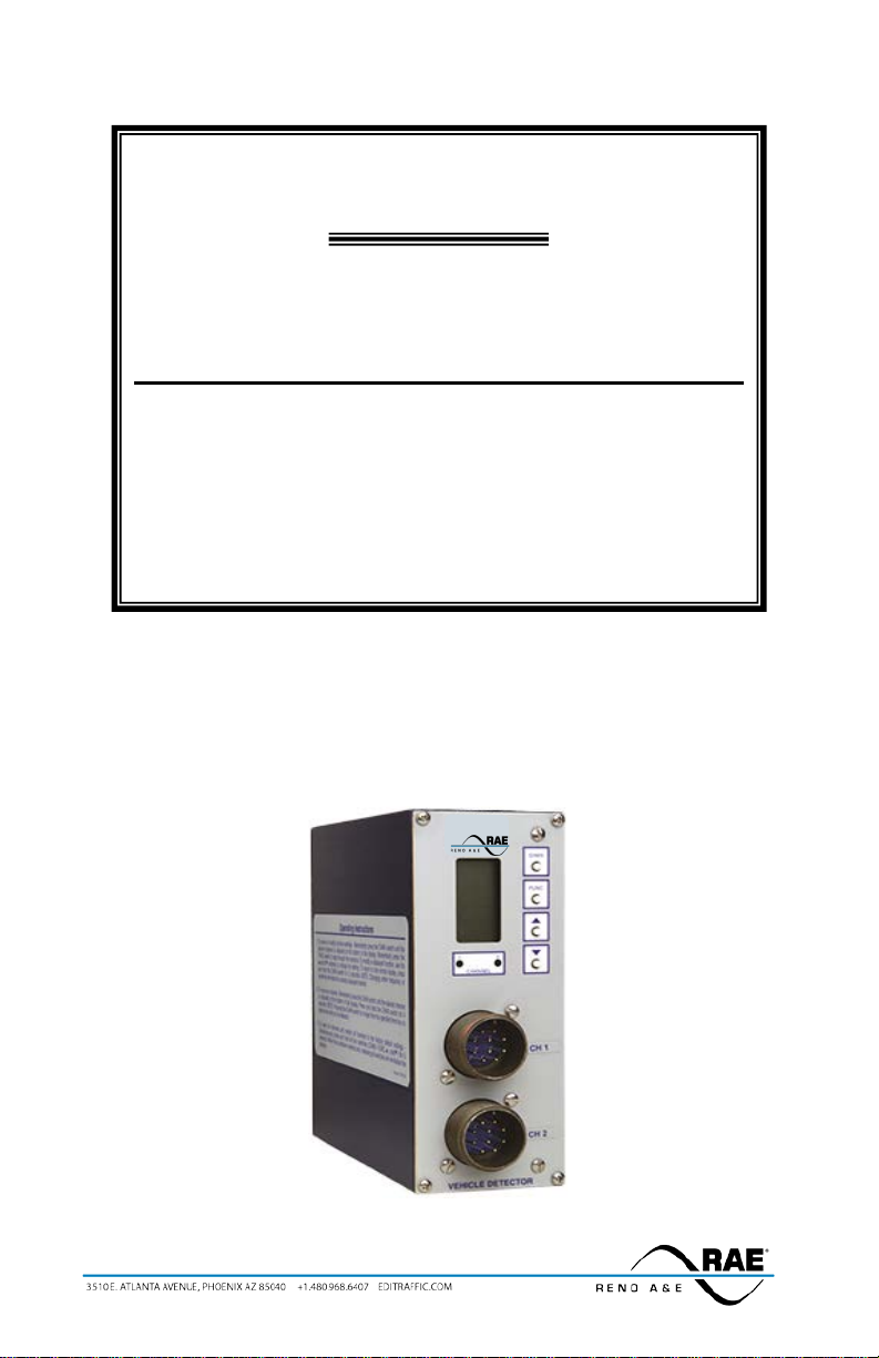
This Operation Manual was written for people installing, operat ing, and maintaining Reno A & E Model S-1201
inductive loop vehicle detectors. Designed to be used in freeway entrance and exit ramp monitoring applicat ions,
the Model S-1201 is a two channel, shelf mount type, inductive loop vehicle detector that meets or exceed NEMA
Standards TS 1-1989. A rear mounted DB-9 serial connector can be used to provide a means of communication
with other related equipment.
The Model S-1201 incorporates a microcontroller that monitors and processes signals from two separate loop /
lead-in circuits and two Phase Green Inputs. The microcontroller uses these inputs to determine how to control the
detector outputs. A Liquid Crystal Display (LCD), two light emitting diodes (LEDs), and four front panel
pushbuttons are used to display and program all detector funct ions. Several diagnostic modes are available to aid
technicians and service personnel in troubleshooting detection problems.
The use of a LCD is what distinguishes this detector from that of other manufacturers. It allows more informat ion,
never before available, to be displayed to the user during normal operation of the detector. T he LCD makes it easy
to view and adjust all programmable detector opt ions and settings. It is no longer necessary to check o r change
detector settings with DIP sw itches. An eight-segment bargraph at the top of the LCD c an be used to provide a
graphical representation of the relative change of inductance as seen by the detecto r at the current sensitivity level.
The bargraph automatically takes into account loop size, loop inductance, number of loops, number of turns, loop
geometry, lead-in length, etc. The bargraph functions as a sliding scale that relates to the programmed Sensitivity
Level. The first (left-most) bargraph segment represents the minimum inductance change necessary for the
detector to output a call at the currently selected sensitivity level. Larger inductance changes will indicate more
segments. Each additional segment indicates that the next sensitivity level has also been met or exceeded. When
used in th is manner, the bargraph provides an indication of whether the sensitivity is set too high or too low,
facilitating the ideal setting of the se ns itivity level.
All programmed settings are stored in non-volatile memory and can only be changed by programming new
settings. Loss of power or a de tector reset will not change any of t he programmed settings. If a loop failure
occurs, the LCD will display the type of lo op failure as L lo (for -25% change or shorted loop conditions) or L hi
(for +25% change or open loop c onditions). Each loop failure is co unted and accumulated in the Loop Failure
Memory. The number of loop failures since the last detector reset or power interruption is very useful information
to have available during analysis of intermittent loop operation.
The Model S-1201 Series detector is a scanning detector. The scanning operation sequentially activates the ON
and OFF cycle of each channel’s oscillator. Since only one channel’s loop(s) is (are) active at a given time,
crosstalk between adjacent loops connected to the same scanning detector is minimized. The Model S-1201
Series’ unique scanning process a lso disconnects the capac itors and dampens t he oscillator during t he OFF cycle.
This eliminates oscillatio n past the O FF point ( ringing or decay) e very time the loop circuit is scanned, w hich can
result in crosstalk. When operating in the Program Mode, the Model S-1201 S eries disp lays t he rea l time loop
frequency reading for each channel. The eight frequency settings can be incremented or decremented to provide
precise frequency readings, removing any guesswork when cha nging frequency settings to eliminate crosstalk.
NOTE: Adjacent loops connected to different c hannels of a non-scanning dete ctor or d ifferent scanning dete ctors
should be set to different frequencies with maximum separation.
The Reno A & E Model S-1201 Series utiliz es the first major innovation in inductive loop detectors since the
introduction of digital detecto rs. The programming of all of the detector’s para meters with four normally open
pushbutton switches not o nly simplifies setup by removing binary coded DIP s witches, but also increases the
reliability of the detector by eliminating the dependence on switch contacts during normal operation. The detailed
descriptions displayed on the LCD eliminate the interpretation of numerous LED flash rates to determine the
detector status. In addition, the Model S-1201 offers t he versatility of softwa re control. Special funct ions are
possible with a simple change of the s ocket-mounted microprocessor. Special functions are defined as unique
options (e.g. Option 6, Opt ion 12, etc.). Spe cial option functio ns are activated thro ugh the use o f the LCD menu
option programming.
889-1909-00 Model S-1201 Operations Manual Rev Apr 2020 Page 1 of 29
Page 8

Section 2 General Characteristics
2.1 LOOP FREQUENCY
There are eight (8) selectable loop frequency settings (normally in t he range of 20 to 100 k ilohertz) per channel.
The actual loop operating frequency is a function of the loop / lead-in network and the components of the loop
oscillator circuit. The d igital display of the actual loop operating frequency for each setting makes it easy to
quickly identify and eliminate crossta lk in the most difficult to configure intersections. The frequency display is
typica lly very st able when t he loop is va cant and ve hicles ar e not passi ng nearby the loops. If the reading is
varyin g by more than ±1 in the last digit, this is an indication of possible crossta lk betwee n loops.
2.2 SENSITIVITY
There are nine (9) selectable sensitivity levels per channel, plus Continuous-Call and Channel-Off. The se nsitivit y
levels are designed so that a one level increase actually doubles the sensitivity and a one level decrease halves the
sensitivity. A unique bargraph d isplayed on t he LCD makes it eas y to quickly set sensitivity at t he ideal level for
any loop / lead-in network configuration. (See Section 3.4 for actual detectio n levels at each sensitivity level.)
C
ONTINUOUS-CALL: Whe n se t t o t he Co nt in uo us -Call state , the c hannel ou tput is co ntinuous ly in t he Call state
regardless of the presence or absence of vehicles over the loop. The loop osc illator is disabled when in the
Continuous-Call state. T his state is indicated b y CALL flashing on the LCD. This option is selected from the
Sensit ivity men u in Progra m Mode and is useful fo r checkin g controlle r respons e and other troubleshooting
activities.
C
HANNEL-OFF: When s et to the Channel-O ff state, the channel output is cont inuously in the No Call state
regardless of the presence or absence of vehicles over the loop. The loop oscillator is disabled when in the
Channel-Off State. This sta te is indicated by OFF flashing on t he LCD. This option is selected from the
Sensitivity menu in Program Mode and is useful for checking co ntroller response and other troubleshooting
activities.
2.3 PRESENCE / PULSE
One of t wo mutuall y exclusive modes of operation for each channel is ava ilable. Presence or Pulse mode is
toggled by momentarily pressing e ither the (UP) or (DOWN) button.
P
RESENCE MODE: Provides a call hold time of at least four minutes (regardless of vehicle size) and typically one
to three hours for an automobile or truck.
P
ULSE MODE: An output Pulse of 125 ±10 milliseconds duration is generated for each vehicle entering the loop
detection zone. Each detected vehicle is insta ntly tuned out if it remains in the loo p detect ion z one lon ger t ha n
two seconds. This enables detection of subsequent vehicles entering the loop detection zone. After each vehicle
leaves the loop detection zone, the cha nnel resumes full sensitivity within 0.5 seconds.
2.4 CALL DELAY
Each channel’s Call Delay is adjustab le fro m 0 to 255 se conds in one second steps. Call Delay time starts coun ting
down when a vehicle enters the loop detection zo ne. The remaining Ca ll Delay time i s continuous ly displayed on
the LCD . W he ne ver a P has e Gr ee n I np ut ( C all D e la y Ove r rid e) si gna l ( pi n J o f t he M S co nne ct or of c ha nne l 1 or
2) is active, the Call Delay func tion for the channel is aborted and the Call Delay time is forced to zero.
2.5 CALL EXTENSION
Each channel’s Call Extension is adjustable from 0 to 25.5 seconds in 0.1 steps. Extension time starts counting
down when the last vehicle clears the loop detection zone. The remaining Call Extension time is continuously
displa ye d o n the LCD . Any ve hic le ent er in g t he lo op det ec t io n zo ne d ur in g the Ca l l Ext ens io n t i me p er iod causes
the channel to return to the Detect state, and later, when the last vehicle clears the loop detection zone, the full Call
Extension time starts counting dow n again. (See Option 3, Call Extension Control, for an a lternate mode of
operation for Call Extension.)
2.6 MAX PRESENCE TIMER
When activated, each channel’s Max Presence timer is adjustable from 1 to 999 seconds in one-second steps. A
setting of OFF turns the Max Presence timer off. The Max Presence function is used to limit presence time, by
automatically resetting the channel. If this function is enabled (ON), the Max Pre sence timer begins counting
down when a call is initiated and t he remaining ti me is continuously displaye d on the LCD. If t he loop becomes
vacant before the Max Presence timer reaches zero, the call is dropped and no automatic reset occurs. If the EndOf-Green (EOG) function is not enabled (OFF) and the call is still present when the Max Presence timer reaches
889-1909-00 Model S-1201 Operations Manual Rev Apr 2020 Page 2 of 29
Page 9

zero, the cha nnel then is aut omatically reset. If the EOG functi on is e nabled ( ON) and the ca ll is st ill present when
the Max Presence timer reaches zero, the channel enters a Wait state. The Wait state continues until either the loop
becomes vacant or the Phase Green Input signal for a channel (pin J of the MS connector) transitions fro m gree n to
not green with the call still present. If the loop becomes vacant first, the call is dropped and no automatic reset
occurs. If the Phase Green Input transitions from green to not green while a channel is in a Wait state, the channe l
is automatically reset. The signals on pin J of the MS connectors of channels 1 and 2 are also called Call Delay
Overrides. (See Section 3.2, Phase Green Input specification for voltage levels.)
2.7 END-OF-GREEN (EOG)
Each channel’s EOG setting can be toggled ON or OFF by momentarily press ing either t he (UP) or (DOWN)
button. The EOG function is used to synchronize resetting of a detector with the termination of t he associated
phase green. The assumption is that t his is the sa fest point in t ime to reset the c hannel. T his assumption is based
on the premise that at the termination of the associated phase green, traffic should be moving, and therefore, a reset
would not result in t he loss of a call when traffic comes to rest over the loop(s). The E OG funct ion is onl y
available when the Max Presence function is set between 1 and 999 seconds. It is not available when the Max
Presence function is OFF. When the EOG function is enabled (ON), the channel will automatically be reset at the
same time the Phase Green Input signal (pin J of the MS connector) transitions from the ON state to the OFF state,
if the Max Presence Time has c ounted down to zero and is resting in t he wait state. The signals on pin J of the MS
connectors of channels 1 and 2 are also called Call Delay Override. (See Section 3.2, Phase Green Input
specifications for voltage levels.)
2.8 DETECTOR ID
This feature is used to assign a unique identification value to the detector for communication purposes. Detector
ID settings ca n range fro m 000 to 253. NOTE: When first init ialized, t he detector ID s etting is 000.
2.9 OPTION 1: LOOP INDUCTANCE DISPLAY
Each cha n ne l’s Loo p I nd uct a nce Dis p la y se tt in g ca n be t o ggle d O N or O FF b y mo me nta r il y pre ss i ng e it her the
(UP) or (DO W N ) b u t to n. W hen this option is enabled (ON), the LCD displays the total loop inducta nce (actual
loop inductance plus actual lead-in inducta nce) in m icrohe nries for loop inducta nce va lues i n the ran ge of 20 to
2500 microhenries. By recording the inductance of the loop / lead-in circuit when it is first insta lled, the actual
inductance can be compared to the expected ind uctance to help identify defective loop / lead-in circuits. Loop /
lead-in inductance can be easily estimated using the simple formulas included in Section 9.7
NOTE: Enabling this option activates i t for both channe ls. Th is option is automat ica lly disabled 15 m inutes after
activation or on loss of power.
of this manual.
2.10 OPTION 2: LOOP INDUCTANCE -∆L/L DISPLAY
Each cha n ne l’s Loo p Ind uct a nce -∆L/L Display sett ing can be toggled ON or OFF by momentarily press ing either
the (UP) or (DOWN) b utton. When t his option is e nabled (ON), the LCD disp lays the percentage o f
induct ance change (-∆L/L value) during the Call state. To f acilitate t he viewing o f the maximum amo unt of
change in the -∆L/L value while traffic is in motion over the detection zone, the channel holds the peak -∆L/L
value for a period of two seconds. NOTE: Enabling t his option activates it for both channels. This option is
automatically disabled 15 minutes after activation or on loss of power.
2.11 OPTION 3: CA L L EXTENSION CONTROL
Each cha nnel’ s Cal l Exte nsion C ontro l set ting ca n be to ggled O N or OF F by mo mentar ily pre ssin g eithe r the
(UP) or (DOWN) button. Whe n t his op ti o n is ena b led (O N), t he c ha nne l wi ll e xt end ca lls fo r the pro g ra mme d
extens ion t ime only whe n the P has e G ree n Inp ut s i gna l (p in J o f t he M S c on nec to r) is ac ti ve. Whe n t h is op t ion is
OFF, the channel extends ALL calls for the programmed extension time. The signals on pin J of the MS
connectors of channels 1 and 2 are also called Call Delay Overrides. (See Section 3.2, Phase Green Input
specifications for voltage levels.)
2.12 OPTION 4: NOISE FILTER DISABLE
The detector’s Noise Filter Disable setting can be toggled ON or OFF by momentarily pressing either the (UP)
or ( DO WN ) b utt o n. W he n Op t io n 4 is e nab le d ( ON ), inte r na l no is e f ilt er in g is d isa ble d t hus p ro vid in g a fas te r
response time. When t his option is OFF, inter nal noise filtering is utilized. When the detector is used in speed
and/or occupancy applications, the noise filter s hould be disabled (i.e. Option 4 ON) to provide the most accurate
data possible. It is recommended t hat this option not be activated. The factory default setting o f OFF provides
stable operation in high crosstalk e nvironments. NOTE: Enabling this option activates it for both channels.
Changing the setting of this feature will reset both detector channels.
889-1909-00 Model S-1201 Operations Manual Rev Apr 2020 Page 3 of 29
Page 10

The Loop Fail Count is not reset when the setting of Option 4 is changed. Also, c hanging t he setting of Optio n 4
will not cause the prior Loop Fail indication to cease (see Section 5.3, Loop Fail Indications).
2.13 OPTION 5: PHASE GREEN LOOP COMPENSATION
Each channel’s Phase Green Loop Compensation setting can be toggled ON or OFF by momentarily pressing
either the (UP) o r (DOWN) button. When Option 5 is enabled (ON), normal loop compensation is used until
the Phase Green Input signal (pin J of the MS connector) becomes active. Once the Phase Green Input signal is
active1, the channel desensitizes the loop. Maximu m desensitization is 0.05% (-∆L/L). This desensitization tunes
out sma ll chan ges, suc h as ad jacent la ne pick up, the refore minimiz ing t he chance of max t iming a n empty lane.
Note: A small motorcycle may also be tuned out in a s hor t pe r iod o f time following the start of Phase Gr ee n. This
option is useful in minimizing false detection resulting from adjacent lane pick up when a channel must be r un with
a high sensitivity setting. When Option 5 is not enabled (OFF), normal loop compensation is used.
2.14 OPTION 6: VEHICLE COUNTING DISPLAY
Option 6 has two parameters, Option 6.0 and Option 6.1.
When Option 6.0 is enabled (ON) for a channel, the normal operating displa y for that c hannel is replaced w ith
the accumulated vehicle count. The unit is capable of accumulating 65,535 vehicle counts before rolling over to
zero. The display will show the hundreds, tens, and o nes digits until the accumulated count e xceeds 999. At
this point the display will alternate be tween the ten thousands and thousands d igits and the remaining three di g its
for hundreds, tens, and ones.
When the detector is first powered up, the detector enters a training mode . Operation in the training mode is
indicated by the accumulated vehicle count flashing on the LCD. Training mode enables the detector to identify
what degree of inductance change a typical vehicle causes as it is detected. When the training period is
complete, the flashing display of the accumulated vehicle count on the LCD will cease and the LCD will show
the actual accumulated vehicle count. The most accurate vehicle counts are obtained once the detector is
operating in this mode, i.e. after the training period is complete.
Option 6.1 is used to reset the accumulated vehicle count for the selected channel. When Option 6.1 is changed
from the OFF state to the ON state, the accumulated vehicle count for the selected channel is reset to zero.
Option 6.1 will always be in the O FF state whe n first vie wed. The acc umulate d ve hicle count is also cleared by
loss of power.
2.15 OPTION 7: VEHICLE COUNTING LOOP CONFIGURATION
Each detector channels’s Vehicle Count ing Loop Configuration setting can be set from 01 to 04. This setting
should indicate the number of loops installed in a single lane. The setting 01 would ind icate a single loop. This
could be a single 6΄ x 6΄ or a long loop such as a 6΄ x 50΄ Quadrupole
number of 6΄ x 6΄ loops installed in a single lane of traffic.
Several factors can influence the count accuracy achieved with this detector:
1. Lanes per Detector - The detector was designed to be used in applications where each channel is used to
count vehicles in a single lane of traffic. It is not intended to be us ed in applications where it is necessary
to count cars across multiple lanes of traffic.
2. Loop Geometry - In the multiple loop settings (02-04), all l oops must be of the same configuration, i.e. the
same number of turns and the same size. Also, all loops must be equally spaced. The ideal spacing for 6 ft.
by 6 ft. loops is 15 ft. center to center or 9 ft. spac ing between loop ed ges. Further, multiple loops should
always be wired in a series network. This is important to ensure that a vehicle passing over the group of
loops c auses the s ame amo u nt o f in d uc t a nce chan ge i n e a c h lo o p . I n the single loop setting (01), square or
rectangular configurations will give slightly better results than Quadr upo le
3. Loop Placement - Loops should a lways be p laced in the center o f the traveled lane. Loops s hould extend
out in front of the stop bar. For turning movements, loops s hould not extend so far out in front of the stop
bar that exiting vehicles would exit more out of the side of the loop than out the fro nt of the loop. If the
detector is operating in the multiple loop mode and other moveme nts of traffi c clippin g the fro nt edge of
the loop are a concern, the detector will only count vehicles that cross more than one loop. It will ignore all
vehicles that clip a single loop.
4. Sensitivity Setting - The se nsiti vity s hould be set so that a single passenger vehicle in the detection zone
creates a seven dot deflection on the bar graph on the LCD.
Whenever the detector is powered up, the sensitivity is cha nged, or the loop configuratio n is changed, the detector
will enter the training mode. W h ile in t h is mo de , t he de t ec t o r is e va l ua ting ind iv i d ual vehic le s pa s sing thr o u gh the
detection zone. This means that no other vehicle can occupy any part of the detectio n zone while a vehicle passes
TM
. The remaining three settings indicate the
TM
configurations.
889-1909-00 Model S-1201 Operations Manual Rev Apr 2020 Page 4 of 29
Page 11
Loop B
Loop A
through. The detector w ill accu mulate cou nts during the training period. Opt imal coun t accurac y will occu r after
the training period is complete. Depending on traffic de nsity and the length of detection zone, t his training period
could take many hours. We recommend installing t he detector the day before actual vehicle counts are to be
collected. This will allow sufficie nt time for the dete ctor to train itse lf. The training pe riod is necessar y to ensure
that the detector can adjust itself to the e xa ct pa rticulars of a given loop installation.
The veh icle counting feature cannot be turned off and is active regardless of any other features that have been
enabled. Even if other features (Delay, Third Car Passage, Directional Logic, or Detector Disconnect) would cause
the normal detector output to be in the No Call state, the vehicle counting feature will still operate correct ly.
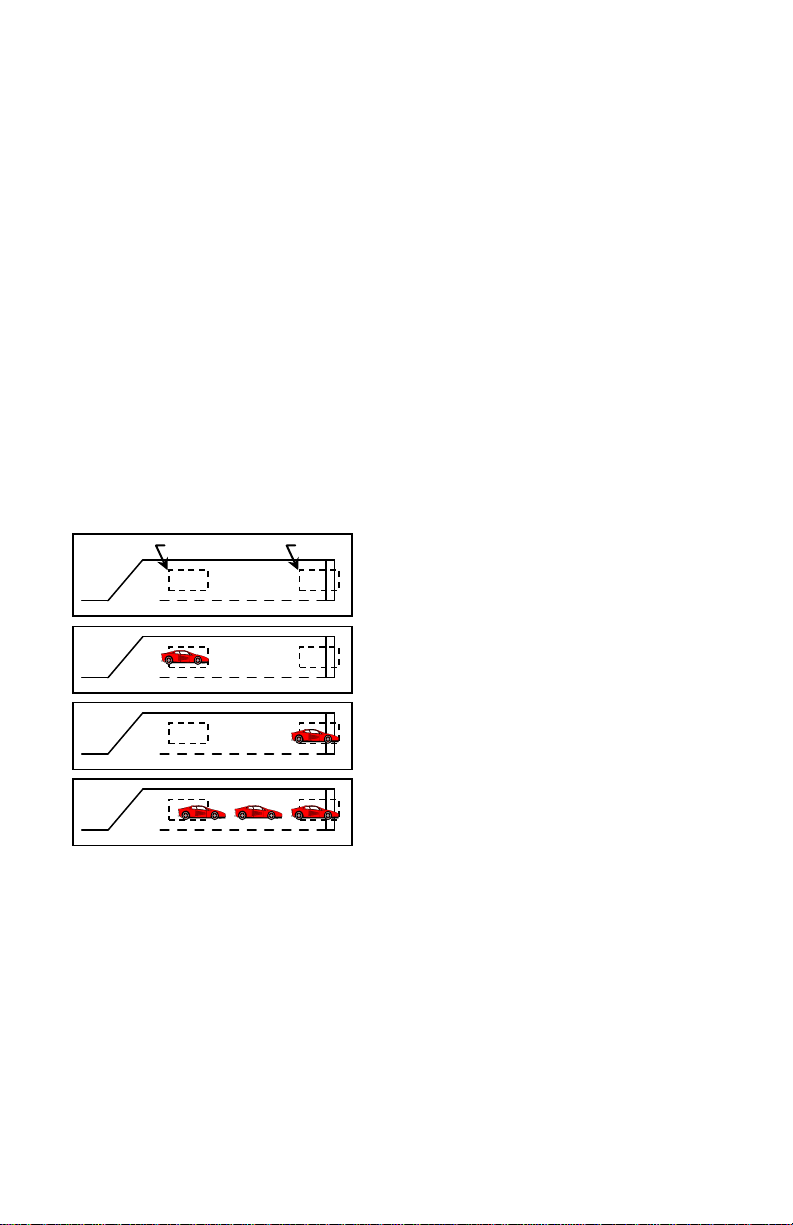
2.16 OPTION 9: THIRD CAR PASSAGE
Each channel’s Third Car Passage setting can be toggled ON or OFF by momentarily pressing either the (UP) or
(DO WN ) b ut to n. O p tio n 9 is a p a ire d cha nne l opt io n. Th is me a ns t hat it t ake s t w o c ha nne ls to i mplement t he
feature. Therefore, when this option is toggled ON or OFF in one channel, its paired channe l is a lso set to the sa me
state. In the Model S-1201, Channel 1 is paired with Channel 2. NOTE: Option 9 is mutually exclusiv e with
Option 10. Turning ON one option will automatically turn OFF the other option.
When Op t ion 9 is e nab led (ON ) , t he o utp u t o f the tw o pa ir ed c ha n ne ls a re log ic a lly AND ed t o get he r. Th is mea ns
that while the loops for both of the paired channels are occupied, a call will be o utput on both channels. While
only one channel is occupied, or neither channel is occupied, a call will not be output for either cha nnel. The first
channel with detection w ill ente r a pe ndin g state w hile wait ing for detect ion o n the other pa ired c hannel. While in
the pending state, the LCD will show Pnd on the d isplay.
This feature is intended to be used in Pro tected / Permissive left turn situations. The expected ins tallation is a stop
bar loop for the left turn lane connected to one channe l, a q ueue detectio n loop (w ith a s mall amount of de lay ti me
programmed) for the left turn lane connected to the other channel, and the output of eithe r channel conne cted to the
Vehicle Call input for the protected movement of the traffic controller.
Basic Installation - Loop A is the Queue Detec tion lo op and
Loop B is the Stop Bar loop.
Car enters Loop A - No ca ll is o utp ut.
Car proceeds to Loop B - No call is output.
Additional cars enter the left t ur n lane - W hen the ba ck o f t he
queue reaches Loop A while a car is still over Loop B, a call
will be output.
When T hird Car P assage is turned o n, as the fi rst vehi cle enter s the left turn lane it will d rive ove r the queue
detection loop. Since there is no vehicle over the stop bar loop, there is no ca ll output generated. The vehicle
advances to the stop bar loop. Still, no output is generate d because there is no vehicle over the queue detection
loop. If the vehicle traffic in the left turn lane backs up to the queue detection loop, t hen t he stop bar loop a nd t he
queue detection loop will both be occupied at the same time. This will cause the detector to generate a call to the
traffic controller to service the protected movement for the left turn. This sho uld hel p cle ar t he q ueue of ve hi cles
in the left turn lane. The spacing between the stop bar loop and the queue detection loop controls the size of the
queue needed to generate a call to the protected movement of the controller. The delay time on the Q ueue
Detection loop should be sufficiently long that vehic les driving over this loop to enter the queue do not generate a
call.
2.17 OPTION 10: DIRECTIONAL LOGIC
Each channel’s Directional Logic setting can be toggled ON or OFF by momentarily pressing either the (UP) or
(DOWN) button. Option 10 is a paired c hannel option. This means that it takes two channe ls to implement t he
feature. Therefore, when this option is toggled ON or OFF in one channel, its paired channe l is a lso set to the sa me
state. In the M odel S-1201, Channe l 1 is p aired with C hanne l 2. NOT E: Opt ion 10 is mutua lly exc lusi ve wit h
Optio n 9. Turni ng ON one o ption will auto matica lly turn O F F the other option.
889-1909-00 Model S-1201 Operations Manual Rev Apr 2020 Page 5 of 29
Page 12

Loop B
Loop A
Basic Ins tallat ion
Car enters Loop A - No call is output
Car enters Loop B - No ca ll is
Car proceeds to Loop B
Car proceeds to Loop A
Call is output o n C hannel A
When Option 10 is enabled (ON), directional logic is enabled. Directional logic starts with a detection on one
channel. This channel will go into the pending state, display Pnd on the LC D , a nd N O T output a c a l l. W hen both
of the paired channe ls have detect ion, the last channel to have d etect ion will output a call until the detection for the
last c ha n ne l e nd s , e ve n if t h e d e te c t ion ends fo r t he fi rs t c hannel. None of t he t i mi n g f un c t io ns of the f ir s t channe l
with a detection will ti me (Delay, Extens ion, Max Presence, a nd Detector Disconnect) a nd the first channel w ill
always operate in the Presence Mode regardless of the programming o f the channel.
This feature is intended to be used in parking lot applications where vehicles can enter or exit from the same lane,
freewa y ra mp s for wro ng w a y de tec t ion, a nd le ft t urn lane s whe re other movements in the interse ction te nd to clip
the detection zone of the left turn lane. The expected installation is two loops, one after the other in the same lane,
spaced anywhere from slightly overlapping to 6 feet apart. NOTE: Contact a Field Engineer at Reno A & E
regarding proper loop configurations and spacing for specific applications.
When Directional Detect ion is turned on, a vehicle entering the first loop will cause that channel to enter t he
pending state. As the vehicle enters the second loop while still occupying the first loop, the seco nd channel will
enter the Call state while the firs t channe l remains in t he pending s tate. A ca ll is never outp ut on the first c hannel
with a d et ec tio n. Und er nor ma l c o ndi tio ns b oth o ut p uts ca n ne ve r be on at the same time. However, if one of the
loops fail, both outputs will come on a nd stay on until the failure is corrected.
Call is output o n C hannel B
2.18 OPTION 11, AUDIBLE DETECT SIGNA L
Each channel’s, Audible Detect Signal setting can be to ggled ON or OFF by momentar ily pressing eithe r the
(UP) or (DOWN) butto n. Only one channel can be turned ON at a time. Turning this option ON for one
channe l automatically t u r ns it O F F fo r t he o t he r channe l. W hen this o p t io n is e na b le d (ON), an audib le signal will
be acti va te d w he ne ver t he detection zone for the selected channel is occupied. The audible signal indicates actual
occupancy of the loop detection zone. Timing a nd disconnect functio ns have no e ffect on t he audible s ignal. This
feature allows a technician to watch the det ection zone on the street and confirm correct detector operation without
having to look at the detector display as well. NOTE: This option is automatical ly disabled 15 minutes after
activation or on loss of power.
2.19 OPTION 12: DETECTOR DISCONNECT
Each channel’s Detector Disconnect setting can be toggled ON o r OFF and the Extens ion timer toggled between
ON and OFF by momenta r il y pr es sing ei t h er t he (UP) or (DOWN) button. The Detector Disconnect feature
require s tha t the Phase Gree n Inp ut for t he cha nne l be connected to the proper controller phase. When the Phase
Green I nput is no t a c t i ve , t he c hannel s hall ope ra te no r mally. W hen the P ha s e Gr e e n I np ut is a c t iv e , t he e xt e nsion
timer will start to count down at the e nd of each detection. If this timer reaches zero before the next detection, this
channel will no longer output a call until the Phase Green Input is not active. Since the extension timer is used as a
disconnect timer while in this mode, two different disconnect types are available:
Option 12.1 OFF: Extension timing s till occurs and the extension timer is a lso the d isconnect timer during phase
green. This will cause the call output to re main in the Call state until disconnect oc curs. This may allow the
user to use gap times appropriate for the advance loops without considering the effects on the stop bar loops.
Option 12.1 ON: E xte ns ion timing is disabled and the extension timer is used as the disconnect timer. T his will
cause the call output to follow the occupation of the loop detection zone until disconnect occurs.
This feature is intended to be used in applications where a loop at the stop ba r is not needed after any waiting
queue in the associated traffic lane is movi ng during t he green p hase. The e xpected installatio n is a sto p bar loop
(typically a 20΄ to 30΄ long detection zone) and an advance detection loop (typically a 6΄ long detection zone) for a
single traffic lane. This feature provides a means for keeping the stop bar loop from placing c alls to the traffic
controller after t he stop bar loop has served its intended purpose during the beginning period of the associated
889-1909-00 Model S-1201 Operations Manual Rev Apr 2020 Page 6 of 29
Page 13

Detection Zone
Phase Green
1 Off
Output w/ 12.1 On
This example assumes an extension time of 2 seconds. The dott ed lines show where disconnect would occur.
Seconds 0 5 10 15 20 25 30 35 40 45 50 55
green phase. The channel connected to the stop bar loop would have the Detector Disconnect feature turned ON
and have a programmed extens ion time tha t functions a s the disconnect time. The cha nnel connected to the
Output w/ 12.
Phase Green is the state of the light (actual Phase Green Input is i nv er ted).
advance detection loop would be programmed as normal.
When the Detector Disconnect feature is turned ON and the signal is not green, the channel outputs calls to the
traffic controller as usual. W hen the signal turns green, vehicles begin to mo ve and eventually the stop bar
detection zone is cleared. At the time that the stop bar detection zone is cleared the disconnect timer begins to
count down. If another vehic le enters the stop bar detection zone be fore the disconnect timer reaches zero, the
channel outputs the new call to the traffic controller and the disconnect t imer is reset to its initial value. Once the
stop bar detection zone remains clear for a time eq ual to the programmed disconnect time, the detector channel is
disabled and will not generate any further calls to the traffic controller until after the green has terminated. When
the stop bar detection loop is disabled, the green phase can only be extended by vehicles detected by the advance
detection loop. NOTE: The disc onnect timer will always time an in itial gap each ti me that the p hase tur ns green.
If Option 12.1 is OFF, the channel will generate an output for the specified extension time at the start of eac h
green phase.
889-1909-00 Model S-1201 Operations Manual Rev Apr 2020 Page 7 of 29
Page 14

Section 3 Specifications
3.1 PHYSICAL
WEIGHT: 34 oz. (963.9 gm).
S
IZE: 6.45 inches (16.38 cm) high x 2.50 inches (6.35 cm) wide x 6.35 inches (16.13 c m) deep (excluding
connectors). Front mounted connecto rs add .675 inch (1.71 c m) to depth measurement, rear mounted connector
adds .215 inch (0.55 cm) to depth measurement.
O
PERATING TEMPERATURE: -40° F to +180° F (-40° C to +82° C).
C
IRCUIT BOARD: Printed circuit boards are 0.062 inch thick FR4 material with 2 oz. copper on both sides and
plated through holes. Circuit board and components are conformal coated with polyure thane.
C
ONNECTORS: (See Section 3.6 for connector pin assignments.)
P
RIMARY CONNECTORS: Two (2) MS3102A-18-1P (front mounted).
S
ECONDARY CONNECTOR: Nine (9) pin, metal s hell, D s u bminia ture re ceptac le w ith gold p lated female contacts
and nuts for retaini ng sc re w s (rear mounted).
3.2 ELECTRICAL
POWER: 89 to 135 VAC, 50/60 Hz, 6 Watts maximum.
L
OOP INDUCTANCE RANGE: 20 to 2500 micro henries w ith a Q factor of 5 or greater.
L
OOP INPUTS: Transformer isolated. The minimum capacitance added is 0.068 microfarad.
L
IGHTNING PROTECTION: Meets and/or exceeds all applicable NEMA TS 1-1989 specifications for transient
voltage protection.
R
ESET: Meets and/or exceeds NEMA TS 1-1989 detector specifications. The detector can be reset by removing
and reapplying power or by changing the setting of Option 4 (Noise Filter Disab le). Each detector channel can be
independently reset by pressing the CHAN button until the desired cha nnel is selected, then pressing and ho lding
the CHAN button fo r t h r ee s e c o nd s . Als o , changing either the sensitivity or loo p fre quency o f a c ha n nel will re s e t
that channel.
P
HASE GREEN INPUTS: Also known as Call Delay Overrides. Meets and/or exceeds all NEMA TS 1-1989
requirements. Applicatio n of a high state voltage (89 to 135 VAC) to pin J of the MS connector of channe l 1 or 2
causes the delay timer for the channel to ab ort the delay t i ming function a nd also pro vides control for Phase Gree n
Loop Co mpensat ion, Max P resence T iming (E nd-of-Green), Extensio n Timing, and Detector Disconnect, if the
features are programmed.
R
ELAY RATING: The relay contacts are rated for 6 Amps maximum, 150 VDC maximum, and 180 Watts maximum
switched power.
3.3 OPERATIONAL
DISPLAY: The LCD backlighting illuminates whenever any pushbutton is pressed. The backlighting will
extinguish 15 minutes after the last pushbutton press.
D
ETECT INDICATOR: Each channel has a super bright, high intensity, red light e mitting diode (LE D) to indicate a
Call Output, D elay Timing, Ext ension Timing, P ending State, or Failed Loop condition.
R
ESPONSE TIME: Meets or exceeds NEMA TS 1-1989 response time specifications. (See Section 3.4 for actual
response times.)
S
ELF-TUNING: The detector automatically tunes and is operational within two seconds after application of power
or after being reset. Full sensitivity and hold time require 30 seconds of operation.
E
NVIRONMENTAL & TRACKING: The detector is fully self-compensating for environmental changes a nd loop drift
over t he full te mperature range and the entire loop inductance range.
G
ROUNDED LOOP OPERATION: The loop is olation transformer allows operation with poor qualit y loops (which may
include one short to ground at a single point).
L
OOP FEEDER LENGTH: Up to 5000 feet (1500 m) maximum with proper feeder cable and appropriate loops.
L
OOP (FAIL) MONITOR: If the to ta l in d ucta nc e o f t he c han ne l’s lo op in put ne tw or k goe s out o f t he ra n ge s pec i fied
for the detector, or rapidly changes by more than ±25 %, the channel will immediate ly e nte r t he Fail-Safe mode and
889-1909-00 Model S-1201 Operations Manual Rev Apr 2020 Page 8 of 29
Page 15

Respons e Time
(Option 4 O FF)
Respons e Time
(Option 4 ON)
OFF
-------
-------
-------
1
0.64%
133 ±27 ms
20 ±4 ms
2
0.32%
133 ±27 ms
20 ±4 ms
3
0.16%
133 ±27 ms
20 ±4 ms
4
0.08%
133 ±27 ms
20 ±4 ms
5
0.04%
133 ±27 ms
20 ±4 ms
6
0.02%
133 ±27 ms
27 ±5 ms
7
0.01%
133 ±27 ms
42 ±8 ms
8
0.005%
133 ±27 ms
72 ±14 ms
9
0.0025%
133 ±27 ms
133 ±27 ms
CALL
-------
-------
-------
add these times together.
Function
Channel 1
Channel 2
Frequency 3 7
Sensitivity 6 6
Delay Time 0 0
Extens ion Time 0 0
Max Presence Time
OFF
OFF
Presence / Pulse Mode
Presence
Presence
EOG
OFF
OFF
Detector ID
000
Option 1 - Loop Inductance Display
OFF
OFF
Option 2 - Loop Inductance -∆L/L Display
OFF
OFF
Option 3 - Call Extension Control
OFF
OFF
Option 4 - Noise Filt er Disable
OFF
OFF
Option 5 - Phase Green Loop Compensation
OFF
OFF
Option 6.0 - Display Vehicle Co u nt
OFF
OFF
Option 6.1 - Reset Vehicle Count
OFF
OFF
Option 7 - Number of Loops
04
04
Option 9 - Third Car Passage
OFF
OFF
Option 10 - Dire c tional Logic
OFF
OFF
Option 11 - Audible Detect Signal
OFF
OFF
Option 12.0 - Detector Disconnect
OFF
OFF
Option 12.1 - Detector Disconnect Type
OFF
OFF
display LOOP FAIL o n the LCD. The type of loop failure will also be disp layed as L lo (for -25% change or
shorted loop conditions) or L hi (for +25% change or open loop conditions). This will continue as long as the loop
fault exists. However, if the detector is reset, or power is momentarily lost, the detector will retune if the
loop inductance is within the acceptable range. If any type of loop failure occurs in one (or more) loop(s) in
a group of two or more loops wired in parallel, the detector will not respond with a Fail-Safe output
following any type of reset. It is essential that multiple loops wired to a common detector channel always be
wired in series to ensure Fail-Safe operation under all circumstances. At the time of a loop failure, the
channel’s LED will begin to flash at a rate of three flashes per second. The LED will continue this display pattern
until the channel is manually reset or power is removed. If the loop self-he als, the LOO P FAIL mess age on the
LCD will extinguish and the channel will resume ope ration in a norma l manner; exce pt the LED w ill continue the
three flashes per second display pattern, thus pro viding an alert that a prior Loop Fail condition has occurred. Each
loop failure for the channel is counted a nd accumulated into the Loop Fail Memory. The total number of loop
failures written into the Loop Fail Memory (since the last power interruption or manual reset) is viewed by
stepping through the channel’s functions in Program Mode until the LOO P FAIL message is displayed.
3.4 TABLE: SENSITIVITY, -∆L/L, AND RESPONSE TIME
Sensitivity -ΔL/L
NOTE: Entries in this table are based on the assumption that both channels are set to the same sensitivity. To approximate response
time for a detector with the channels set to different sensitivities, look up the response time for each channel and divide it by two, then
Noise Filter Enabled
Noise Filter Disabled
3.5 TABLE: DEFAULT SETTINGS
889-1909-00 Model S-1201 Operations Manual Rev Apr 2020 Page 9 of 29
Page 16

Pin
Function
Pin
Function
A
Power, Neutral, 120 VAC
A No Co nnection
B
Channel 1 Output, Relay Common
B Channel 2 Output, Relay Common
C
Power, Line, 120 VAC
C No Connection
D
Channel 1 Loop Input
D Channel 2 Loop Input
E
Channel 1 Loop Input
E Channel 2 Loop Input
F
Channel 1 Output, Relay Normally Open
F Channel 2 Output, Relay Normally Open
True CountTM Channel 1 Output,
Relay Normally Open
True CountTM Channel 2 Output,
Relay Normally Open
H
Chassis Ground
H Chassis Ground
True CountTM Channel 1 Output,
Relay Common
True CountTM Channel 2 Output,
Relay Common
J
Channel 1 Phase Green Input (Delay Override)
J Channel 2 Phase Green Input (Delay Override)
NOTE: Relay contact states are shown with power applied, loop(s) connected, and no vehicle(s) present.
Pin
Function
1
No Connection
2
RS-232 TX Out
3
RS-232 RX In
4
No Connection
5
Logic Ground
6
No Connection
7
No Connection
8
No Connection
9
No Connection
3.6 TABLE: PIN ASSIGNMENTS
Primary Connectors
C
HANNEL 1 CONNECTOR CHANNEL 2 CONNECTOR
G
I
Secondary Connec t or
DB-9
SERIAL CONNECTOR
G
I
889-1909-00 Model S-1201 Operations Manual Rev Apr 2020 Page 10 of 29
Page 17

FUNC
CHAN
1
2
CHANNEL
MODEL S
VEHICLE DETECTOR
CH 1
CH 2
-∆L/L
FREQ
LOOP FAIL
OPTIO
MAX
OFEOSCANNI
EXTENSION
SENSITIVITY
DELA
PULS
SECONDS
ON
Seven Segment Display
Vehicle Count
Parameter Description
Function Select Pushbutton
Channel Select Pushbutton
Press and Hold for Three
UP Pushbutton
Bargraph
Numbered Loop Symbols
LED Indicators
DOWN Pushbutton
MODEL S-1201
Section 4 User Interface
• Vehicle Signal Strength
• Frequency Setting
• Parameter Values
• Timer Countdown
• Frequency Reading
• Inductance Value
• -∆L/L Value
• Pending Call State
• Type of Loop Failure
• L hi = Open Loop or L
High
• L lo = Shorted Loop or L
Low
•
• Name of Parameter
• Timer in Operation
• Channel Displayed
• Flashing = Program Mode
• Call
• Delay Time in Progress
• Extension Time in Progress
• Pending Call State
• Loop Fault has Occurred
• Change Displayed Channel
Press and Release
• Exit Program Mode
Press and Hold for One Second
• RESET Channel
Seconds
• Press Momentarily to Enter
Program Mode and to Step
Through Parameters
• Increments Values
• Toggles ON and OFF
• Decrements Values
• Toggles ON and OFF
NOTE: There are no internal switches or jumpers to set.
889-1909-00 Model S-1201 Operations Manual Rev Apr 2020 Page 11 of 29
Page 18

FREQ KHZ
1
©
SENSITIVITY
1
©
©
PULSE
1
Section 5 Installation and Set-Up
The detector has no DIP switches or jumpers to configure. Connect the detector to an appropriately wired harness
and apply power. If the detector is not new from the factory, it may be advantageous to reset the detect or back to
the factory defaults to avoid having to check every setting for each channel. To reset the detector to factory
defaul t, pres s and ho ld all fo ur pus hbutto n switc hes simu ltaneo usly fo r five s econds . When a ll four b uttons are
depressed, the displa y will s tart co unting d own from five (5 ). W hen t he countdown r eaches ze ro (0), releas ing the
pushbuttons will reload the factory defaults and reset both channels.
All operating parameters can be adjusted from the front panel. The detector continues to operate normally while it
is in t he Program Mode . The value cur r ently displayed is alw ays the actua l value being use d. Exa mple: If you are
changing the delay time, the time displayed at the instant that a vehicle entere d the detection zone for that channel
would be the value used for the delay timer.
Pressing the FUNC button enters t he Progra m Mode. The FUNC button has a n auto repeat function. This a llows
quick navigation to the desired parameter. T he FUNC button only moves forward through all of the parameters.
There is no way to move backwards through the parameters .
While viewing any parameter, pressing t he CHAN button will display the same para meter for the next channel.
The currently selected channel is indicated at the bottom of the LCD. Pressing and holding the CHAN butt on for
one second will exit the Program Mode and return to the Normal Mode.
Pressi ng and ho lding e ither the (UP) or (D OWN) b utton wi ll cause the val ue to cha nge rap idly unt il the
button is released.
5.1 PROGRAM MODE DISPLAY SCREENS
PARAMETER ...................Frequency.
S
ETTINGS ........................E ight (8) S elections - 1 to 8.
S
ETTING DISPLAYED ......Bargraph indicates settings from 1 (left) to 8 (rig ht).
7
SEGMENT DISPLAY ......Actual Frequency of the loop circuit. Typically 20.0 to 99.9
D
EFAULT SETTING..........Channel 1 = 3, Channe l 2 = 7.
E
XAMPLE ........................Frequency setting 4 is selected for channel 1. The loop
N
OTES .............................Changing the frequenc y will reset the channe l. An unstable
P
ARAMETER ...................Sensitivity.
S
ETTINGS ........................11 Selections - 1 to 9, OFF, or CALL.
S
ETTING DISPLAYED ......7-segment display will sho w the currently selected setti ng.
7
SEGMENT DISPLAY ......Currently selected Sensiti vity.
D
EFAULT SETTING..........6 fo r bot h c hanne ls.
E
XAMPLE ........................Sensitivity 5 is selected for channel 1.
N
OTES .............................Changing the s ensiti vity wil l reset the channel. If the chan nel is
P
ARAMETER ...................Presence / Pulse Mode.
S
ETTINGS ........................Presence or Pulse.
S
ETTING DISPLAYED ......The word PRESENCE or PULSE will be displayed.
7
SEGMENT DISPLAY ......Blank.
D
EFAULT SETTING..........Presence for both channels.
E
XAMPLE ........................Pulse Mode is selected for channel 1.
N
OTES .............................If the channel is in the call state when this parameter is
kilohertz.
frequency is 34.9 kHz.
frequency display varying more than ±0.2 kilohertz may
indicate loop crosstalk or other interference.
in the call state when viewing this pa rameter, the bargraph will
show t he s tre ngt h of veh icle ca lls s o tha t t he c orre ct s ens it ivit y
can be verified from this screen.
changed, the change will not take effect until the detection zone
is empty or the channel is reset.
889-1909-00 Model S-1201 Operations Manual Rev Apr 2020 Page 12 of 29
Page 19

©
DELAY
SECONDS
1
EXTENSION
SECONDS
1
©
MAX PRESENCE
SECONDS
1
©
EOG
1
ON © OPTION
1
ON © OPTION
OFF
1
©
ARAMETER ...................Delay.
P
S
ETTINGS ........................256 Selections - 0 to 255 Seconds in one-se cond steps.
S
ETTING DISPLAYED ......7-segment display will sho w the currently selected setti ng.
7
SEGMENT DISPLAY ......Currently selected Delay time in seconds.
D
EFAULT SETTING..........0 seconds for both channels.
E
XAMPLE ........................Delay of 10 seconds selected for channel 1.
N
OTES .............................If the cha n ne l’s detection zone is occupied when this parameter
P
ARAMETER ...................Extension.
S
ETTINGS ........................256 Selections - 0 to 25.5 Sec onds in 0.1 steps.
S
ETTING DISPLAYED ......7-segment display will show the currently selected setti ng.
7
SEGMENT DISPLAY ......Currently selected Extension time in seconds.
D
EFAULT SETTING..........0 seconds for both channels.
E
XAMPLE ........................E xt ension of 2.5 seconds selected for channel 1.
N
OTES .............................This pa ramet er wil l hold t he Disconnect timer value if Option
P
ARAMETER ...................Max Presence.
S
ETTINGS ........................1000 Selections - 1 second to 999 seco nds or O FF.
S
ETTING DISPLAYED ......7-segment display will show currently selected sett ing.
7
SEGMENT DISPLAY ......Currently selected Max Presence time in seconds.
D
EFAULT SETTING..........OFF for both channels.
E
XAMPLE ........................M ax Prese nce is turned OFF f or chan nel 1.
N
OTES .............................If the channel’s detection zone is occupied when this parameter
P
ARAMETER ...................EOG (End Of Green).
S
ETTINGS ........................ON or OFF.
S
ETTING DISPLAYED ......The word ON or OFF will be displayed.
7
SEGMENT DISPLAY ......Blank.
D
EFAULT SETTING..........OFF for both channels.
E
XAMPLE ........................EOG is turned ON for channel 1.
N
OTES .............................This parameter is only displayed if the Max Presence setting for
P
ARAMETER ...................Option 1 (Loop / Lead-In Induc tance Display).
S
ETTINGS ........................ON or OFF.
S
ETTING DISPLAYED ......The word ON or OFF will be displayed.
7
SEGMENT DISPLAY ......The number of this option.
D
EFAULT SETTING..........OFF for both channels.
E
XAMPLE ........................Option 1 is turned ON for all channels
NOTES .............................This option is a detector wide setting. Changing it for one
P
ARAMETER ...................Option 2 (Perce nt age of Inducta nce change, -∆L/L).
S
ETTINGS ........................ON or OFF.
S
ETTING DISPLAYED ......The word ON or OFF will be displayed.
7
SEGMENT DISPLAY ......The number of this option.
D
EFAULT SETTING..........OFF for both channels.
E
XAMPLE ........................Option 2 is turned OFF for all channels.
N
OTES .............................This option is a detector wide setting. Changing it for one
is changed, the change will not take effect until the detection
zone is empty or the channel is re set.
12.0 is ON and extension will not be added to a vehicle call if
Option 12.0 and 12.1 are ON.
is changed, the change will not take effect until the detection
zone is empty or the channel is re set.
the cha nnel ha s bee n prog ramme d with a value betw een 1 a nd
999. Operation of this feature requires that the Phase Green
Inputs be correctly connected to the controller phase green
circuitry.
channel changes it for both channels. This option will
automatically turn off 15 minutes after being activated or on
loss of power.
channel changes it for both channels. This option will
automatically turn off 15 minutes after being activated o r on
loss of power.
889-1909-00 Model S-1201 Operations Manual Rev Apr 2020 Page 13 of 29
Page 20

OPTION
1
ON © OPTION
OFF
1
©
OPTION
1
ON
©
OPTION
1
ON
©
OPTION
OFF
1
©
OPTION
1
©
PARAMETER ...................Option 3 (Call Extension Co ntrol).
S
ETTINGS ........................ON or OFF.
S
ETTING DISPLAYED ......The word ON or OFF will be displayed.
7
SEGMENT DISPLAY ......The number of this option.
D
EFAULT SETTING..........OFF for both channels.
E
XAMPLE ........................Option 3 is turned ON for channel 1.
N
OTES .............................Operation of this option requires that the Phase Green Inputs be
P
ARAMETER ...................Option 4 ( Noise F ilter D isable).
S
ETTINGS ........................ON or OFF.
S
ETTING DISPLAYED ......The word ON or OFF will be displayed.
7
SEGMENT DISPLAY ......The number of this option.
D
EFAULT SETTING..........OFF for both channels.
E
XAMPLE ........................Option 4 is turned OFF for all cha nnels.
N
OTES .............................This option is a detector wide setting. Changing it for one
P
ARAMETER ...................Option 5 (Phase Green Loop Compensation).
S
ETTINGS ........................ON or OFF.
S
ETTING DISPLAYED ......The word ON or OFF will be displayed.
7
SEGMENT DISPLAY ......The number of this option.
D
EFAULT SETTING..........OFF for bot h channe ls.
E
XAMPLE ........................Option 5 is turned ON for channel 1.
N
OTES .............................Operation of this option requires that the Phase Gree n Inputs be
P
ARAMETER ...................Option 6.0 (Dis play Vehicle Count).
S
ETTINGS ........................ON or OFF.
S
ETTING DISPLAYED ......The word ON or OFF will be displayed.
7
SEGMENT DISPLAY ......The number of this option.
D
EFAULT SETTING..........OFF for both channels.
E
XAMPLE ........................Option 6.0 is turned ON for channel 1.
P
ARAMETER ...................Option 6.1 (Reset Vehicle Count).
S
ETTINGS ........................ON or OFF.
S
ETTING DISPLAYED ......The word ON or OFF will be displayed.
7
SEGMENT DISPLAY ......The number of this option.
D
EFAULT SETTING..........OFF for both channels.
E
XAMPLE ........................Option 6.1 is turned O FF for channe l 1.
P
ARAMETER ...................Option 7 (Number of Loops).
SETTINGS ........................7.01 through 7.05.
S
ETTING DISPLAYED ......7-segment display will show currently se lec te d s e tting.
7
SEGMENT DISPLAY ......The number of this option.
D
EFAULT SETTING..........7.04 for both channels.
E
XAMPLE ........................The number of loops is set to 4 for channel 1.
correctly connected to the controller phase green circuitry.
channe l change s it for both cha nnels. Chang ing the s etting o f
this option will reset both detector channels. It is
recommended that this option be set to OFF for normal
operation.
correctly connected to the controller phase green circuitry.
889-1909-00 Model S-1201 Operations Manual Rev Apr 2020 Page 14 of 29
Page 21

OPTION
OFF
1
©
OPTION
OFF
1
©
OPTION
1
ON
©
OPTION
1
ON
©
OPTION
OFF
1
© © ©
PARAMETER ...................Option 9 (Third Car Passage).
S
ETTINGS ........................ON or OFF.
S
ETTING DISPLAYED ......The word ON or OFF will be displayed.
7
SEGMENT DISPLAY ......The number of this option.
D
EFAULT SETTING..........OFF for both channels.
E
XAMPLE ........................Option 9 is turned OFF for cha nnels 1 and 2.
N
OTES .............................This is a paired channel option. Channel 1 is paired with
P
ARAMETER ...................Option 1 0 (Directional Logic ) .
S
ETTINGS ........................ON or OFF.
S
ETTING DISPLAYED ......The word ON or OFF will be displayed.
7
SEGMENT DISPLAY ......The number of this option.
D
EFAULT SETTING..........OFF for both channels.
E
XAMPLE ........................Option 10 is turned OFF for cha nnels 1 and 2.
N
OTES .............................This is a paired channel option. Channel 1 is paired with
P
ARAMETER ...................Option 11 (Audible Detect).
S
ETTINGS ........................ON or OFF.
S
ETTING DISPLAYED ......The word ON or OFF will be displayed.
7
SEGMENT DISPLAY ......The number of this option.
D
EFAULT SETTING..........OFF for both channels.
E
XAMPLE ........................Option 11 is turned ON for channel 1.
N
OTES .............................This op tion is mutua lly excl usive w ith the same op tion on t he
P
ARAMETER ...................Option 12.0 (Detector Disconnect).
S
ETTINGS ........................ON or OFF.
S
ETTING DISPLAYED ......The word ON or OFF will be displayed.
7
SEGMENT DISPLAY ......The number of this option.
D
EFAULT SETTING..........OFF for both channels.
E
XAMPLE ........................Option 12.0 is turned ON for channel 1.
N
OTES .............................When this option is turned ON, the value entered in Extension
P
ARAMETER ...................Option 12.1 (Detector Disconnect Type).
S
ETTINGS ........................ON or OFF.
S
ETTING DISPLAYED ......The word ON or OFF wil l be displayed.
7
SEGMENT DISPLAY ......The number of this option.
D
EFAULT SETTING..........OFF for both channels.
E
XAMPLE ........................Option 12.1 is turned O FF for cha nnel 1.
N
OTES .............................When this option is turned ON, the value entered in Extension
channe l 2. Cha nging t he setti ng for o ne chan nel also change s
the setting for the paired channel. Turning ON Option 9
automatically turns OFF Opti on 10.
channe l 2. Cha nging t he setti ng for o ne chan nel also change s
the setting for the paired channel. Turning ON Option 10
automatically turns OFF Opti on 9.
other channel. Turning it ON for one c hannel turns it OFF for
the other channel. T his option will a utomatically turn OFF 15
minutes after being activated or on loss of power.
time is used as a Disconnect time. Operation of this opt ion
requires that the Phase Green Inputs be correctly connected to
the controlle r phase green circuitry.
time is used as a Disconnect time and no extension of the call is
made. When Opt ion 12.1 is turned OFF, Extension time is
active. Extension time and Disconnect time function
concurrently.
P
ARAMETER .............................Detector ID.
S
ETTINGS ..................................254 Selections - 000 to 253.
SETTING DISPLAYED ................Alternates between the two screens
shown
7
SEGMENT DISPLAY ................The current detector ID setting.
D
EFAULT SETTING....................000.
E
XAMPLE ..................................The detector ID setting of this
detector is 73.
889-1909-00 Model S-1201 Operations Manual Rev Apr 2020 Page 15 of 29
Page 22

LOOP FAIL
1
©
© 1 © 1 ©
PRESENCE
PRESENCE
1
©
PULSE
1
©
PARAMETER ...................Loop Fail.
S
ETTINGS ........................Pressing the (UP) or (DOWN) button will clear the Loop
Fail memo r y.
S
ETTING DISPLAYED ......View only.
7
SEGMENT DISPLAY ......Loop Failures since the last time it was cle ared manually or due
to power failure.
D
EFAULT SETTING..........0 fo r bot h c hanne ls.
E
XAMPLE ........................There are eight (8) Loop Failures in the accumulator for
channel 1.
N
OTES .............................Count will be reset to zero a fter loss of power, by pressing the
(UP) or (DOWN) butt on, or by resett ing the c hannel.
ARAMETER .............................Firmwar e Vers ion and R evision.
P
S
ETTINGS ..................................View Only.
S
ETTING DISPLAYED ................View Only.
7
SEGMENT DISPLAY ................Model letter and fir mware version on
D
EFAULT SETTING....................Not Applicable.
E
XAMPLE ..................................Model S firmware version 34,
5.2 NORMAL MODE DISPLAY SCREENS
STATE .............................Idle.
B
ARGRAPH DISPLAY .......OFF.
7
SEGMENT DISPLAY ......Three Dashes.
T
EXT ...............................PULSE or PRESENCE indicating detection mode of the
C
HANNEL LED ...............OFF.
C
HANNEL OUTPUT..........OFF.
E
XAMPLE ........................Channel 1 is idle and in the presence mode of detection.
N
OTES .............................This is the normal state for the display when the loop detection
S
TATE .............................Presence Call.
B
ARGRAPH DISPLAY .......N umbe r of se nsit ivit y le vels t hat t he ind ucta nce c hange caus ed
7
SEGMENT DISPLAY ......Call.
T
EXT ...............................PRESENCE, indicating detection mode of the channel.
C
HANNEL LED ...............Solid ON.
C
HANNEL OUTPUT..........ON.
E
XAMPLE ........................Channel 1 detection zone is occupied by a vehicle that exceeds
S
TATE .............................Pulse Cal l.
B
ARGRAPH DISPLAY .......OFF.
7
SEGMENT DISPLAY ......-
T
EXT ...............................PULSE, indicating detection mode of the channel.
C
HANNEL LED ...............ON for 125 milliseconds.
C
HANNEL OUTPUT..........ON for 125 milliseconds.
EXAMPLE ........................Channel 1 detection zone is occupied and channel 1 is
N
OTES .............................This display is only shown for 125 milliseconds (t he duration of
channel.
zone is unoccup ied and t he channe l does not have a ny timin g
options set.
by the vehicle exceeds the detection threshold (first dot =
current sensitivity level, second dot = next lower sensitivity
level, etc.) .
the detection threshold by four (4) s ensitivity levels and channel
1 is outputtin g a call.
outputting a call of 125 milliseconds duration.
the pulse output).
Π
- for 125 milliseconds.
one screen and firmware revision on
the other screen.
revision .00.
889-1909-00 Model S-1201 Operations Manual Rev Apr 2020 Page 16 of 29
Page 23

PRESENCE
DELAY
SECONDS
1
©
PRESENCE
EXTENSION
SECONDS
1
©
MAX PRESENCE
SECONDS
1
©
MAX PRESENCE
EOG
SECONDS
1
©
TATE .............................Ti ming Delay.
S
B
ARGRAPH DISPLAY .......N umbe r of se nsit ivit y le vels t hat t he ind ucta nce c hange caus ed
7
SEGMENT DISPLAY ......Countdown of remaining Delay time (in seconds).
T
EXT ...............................SEC O N DS, DELAY, and PULSE or PRESENCE.
C
HANNEL LED ...............Four Hz flash rate w ith 50% duty cycle (125 ms ON, 125 ms
C
HANNEL OUTPUT..........OFF.
E
XAMPLE ........................Channel 1 detection zone is occupied by a vehicle that exceeds
S
TATE .............................Timi ng E xt e nsion.
B
ARGRAPH DISPLAY .......OFF.
7
SEGMENT DISPLAY ......Countdown of remaining Extension time (in seconds).
T
EXT ...............................SEC O N DS, EXTENSION, and PULSE or PRESEN CE.
C
HANNEL LED ...............16.6 Hz flash rate with 50% duty cycle (30 ms ON, 30 ms
C
HANNEL OUTPUT..........ON.
E
XAMPLE ........................Cha nne l 1 de tect ion z one is vac ant, the re are two and one half
N
OTES .............................When Option 12.0 is ON and 12.1 is O FF, the Extension timer
S
TATE .............................Ti ming Ma x Presence.
B
ARGRAPH DISPLAY .......N umbe r of se nsit ivit y le vels t hat t he ind ucta nce c hange caus ed
7
SEGMENT DISPLAY ......Countdown of remaining seconds of Max Presence.
T
EXT ...............................SEC O N DS and MAX PRESEN CE.
C
HANNEL LED ...............Solid ON.
C
HANNEL OUTPUT..........ON.
E
XAMPLE ........................Channel 1 detection zone is occupied by a vehicle that exceeds
S
TATE .............................Max Presence Timed Out and Waiting for End Of Green.
B
ARGRAPH DISPLAY .......N umbe r of se nsit ivit y le vels t hat t he ind ucta nce c hange caus ed
7
SEGMENT DISPLAY ......000 - Showing that the Max P r esence timer has timed out.
T
EXT ...............................SECONDS, MAX PRESENCE, and EOG (EOG will be
C
HANNEL LED ...............Solid ON.
C
HANNEL OUTPUT..........ON.
E
XAMPLE ........................Channel 1 detection zone is occupied by a vehicle that exceeds
by the vehicle exceeds the detection threshold (first dot =
current sensitivity level, second dot = next lower sensitivity
level, etc.) .
OFF).
the detection threshold by two (2) sensitivity levels, there are
three (3) seconds of Delay remaining, and channel 1 is not
outputting a call.
OFF).
2.5 seconds of Extension time remaining, and channel 1 is
outputting a call.
becomes the Disconnect timer.
by the vehicle exceeds the detection threshold (first dot =
current sensitivity level, second dot = next lower sensitivity
level, etc.) .
the detection threshold by five (5 ) sensitivity levels, there are
30 seconds of Max Presence remaining, and channel 1 is
outputting a call.
by the vehicle exceeds the detection threshold (first dot =
current sensitivity level, second dot = next lower sensitivity
level, etc.) .
flashing).
the detection threshold by five (5) sensitivity levels, Max
Presence has timed out and is waiting fo r the End Of Green,
and channel 1 is outputting a call.
889-1909-00 Model S-1201 Operations Manual Rev Apr 2020 Page 17 of 29
Page 24

PRESENCE
1
©
L =
1
©
-∆L/L =
1
©
STATE .............................Pending.
B
ARGRAPH DISPLAY .......Numb er o f sens itiv ity le vels that t he in duc tance chan ge ca used
7
SEGMENT DISPLAY ......Pnd.
T
EXT ...............................PULSE or PRESENCE indicating detection mode of the
C
HANNEL LED ...............3.3 Hz flash rate with 83% duty cycle (250 ms ON, 25 ms
C
HANNEL OUTPUT..........OFF.
E
XAMPLE ........................Channel 1 detection zone is occupied by a vehicle that exceeds
N
OTES .............................The Pending sta te is used whe n the channel w ould normal ly
S
TATE .............................Loop Inductance Disp lay (Optio n 1 ON).
B
ARGRAPH DISPLAY .......O FF if no vehicle is detected. Number of sensitivity le ve ls that
7
SEGMENT DISPLAY ......Loop / Lead-In circuit inducta nce in micr o hen rie s . I f t he va lue
T
EXT ...............................L=.
C
HANNEL LED ...............The detect LED operates normally indicating call, no call,
C
HANNEL OUTPUT..........The channel o utput operates normall y.
E
XAMPLE ........................Channel 1 Loop / Lead-I n ci rc uit i nd uc ta nc e is 98 mic ro he n rie s
N
OTES .............................If Option 2 (-∆L/L D ispla y) is ON , th is dis play is onl y visib le
S
TATE .............................Loop Inductance -∆L/L Display (% Change) (Opt io n 2 ON).
B
ARGRAPH DISPLAY .......OFF.
7
SEGMENT DISPLAY ......Percentage of change in inductance of the Loop / Lead-In
T
EXT ...............................-∆L/L.
C
HANNEL LED ...............The detect LED operates normally indicating call, no call,
C
HANNEL OUTPUT..........The channel o utput operates normall y.
E
XAMPLE ........................Percentage change of inductance of the call on channel 1 is
N
OTES .............................This display is only visible while the channel is detecting a
by the vehicle exceeds the detection threshold (first dot =
current sensitivity level, second dot = next lower sensitivity
level, etc.) .
channel.
OFF).
the detection threshold by seven (7) sensitivity levels and
channel 1 is not outputting a ca ll. Either Option 9 (Third Car
Passage), Option 10 (Directional Logic), or Option 12 (Detector
Disconnect) has been selected.
output a call but is not, due to the operational functions of
Options 9 (Third Car Passage), Option 10 (Directional Lo gic),
or Option 12 (Detector Disconnect).
the inductance change caused by the vehicle exceeds the
detection threshold (firs t dot = current se nsitivity level, seco nd
dot = next lower sensitivity level, etc.) if a vehicle is detected.
exceeds 999, the display will alternate between t he thousands
place (1 or 2) and the lower three digits of the inductance value.
delay, extension, and / or pending as expected .
and channel 1 is not detecting a vehicle.
when the channel is not detect i ng a vehicle.
circuit.
delay, extension, and /or pend ing as expected .
0.087%.
vehicle and not timing any functions.
889-1909-00 Model S-1201 Operations Manual Rev Apr 2020 Page 18 of 29
Page 25

Field
Length (Bytes)
Description
Address
1
Detector ID (Address )
Checksum 1 Additive Check of the First Two Bytes of the Message
-∆L/L =
LOOP FAIL
OPTION
MAX PRESENCE
OFF
EOG
SCANNING
EXTENSION
SENSITIVITY
DELAY
PULSE
SECONDS
3 2 1
4
ON
© 1 © 1 ©
STATE .......................................Accumulated Vehicle Count Display
B
ARGRAPH DISPLAY .................OFF if no vehicle is detected.
7
SEGMENT DISPLAY ................Alternates between upper two digits
T
EXT .........................................None.
C
HANNEL LED .........................The detect LED operates normally
C
HANNEL OUTPUT....................The channel o u t put operates normally.
E
XAMPLE ..................................The accumulated vehicle count for
N
OTES .......................................This display will flash while the
S
TATE .............................LCD Tes t .
B
ARGRAPH DISPLAY .......A ll segme nts on.
7
SEGMENT DISPLAY ......All segments on.
T
EXT ...............................All se gments on.
C
HANNEL LED ...............The detect LED operates normally indicating call, no call,
delay, extension, and /or pend ing as expected .
C
HANNEL OUTPUT..........The channel o utput operates normall y.
E
XAMPLE ........................All segments on.
N
OTES .............................This display is visible whenever two or three pushbutton
switches are pressed at the same time.
(Option 6.0 ON).
Number of sensit ivity levels that the
inductance change caused by the
vehicle exceeds the detection
threshold (first dot = current
sensitivity level, second dot = next
lower sensitivity level, etc.) if a
vehicle is detected.
and the lower three digits. If the
upper two digits are zero, they are not
displayed at all and only the lower
three digits will be displayed.
indicating call, no call, delay,
extension, and/or pending as
expected.
channel 1 is 21,187.
detector is in the training mode.
5.3 DETECTOR ID / COMMUNICATION PROOCOL
The Model S-1201 detector has built-in provision for communicat ion with external equipment typ ically used in
freeway entrance and exit ra mp monitoring applications. In instances where multiple traffic lanes are monitored, it
is necessary for each detector in the system to have a unique identification signature or address in order for the
ramp traffic monitoring equip ment to accurately determine lane vo lume at any given time. The S-1201 can be
assigned one of 254 ID settings ranging from 000 to 253. The factory default ID setting is 000.
Communication interface is via a DB-9 serial connector mounted on the rear of the detector. Refer to the table in
Section 3.6 for connector pin assignments. The transmit / receive rate is 9,600 bits per second (no parity, one stop
bit). The tables below list the various transmit / receive funct ions.
Transmit Mode (Commands to Detector )
Command 1
889-1909-00 Model S-1201 Operations Manual Rev Apr 2020 Page 19 of 29
1 = Poll for Count
2 = Clear Count
3 = Reset
Page 26

Field
Length (Bytes)
Description
Address
1
Detector ID (Address )
Four Byte Integer (Current Count)
Byte 3 = High Byte o f Channel 2 C ounts
Detector Status Bi t
Bit 7 = Unassigned
Checksum 1 Additive Check of the First Six Bytes of the Message
LOOP FAIL
1
©
+25% change Or
LOOP FAIL
1
©
-25% change Or
conditions.
Receive Mode (Responses from Detector)
Count 4
Status 1
Byte 0 = Low Byte of Channel 1 Counts
Byte 1 = High Byte o f Channel 1 C ounts
Byte 2 = Low Byte of Channel 2 Counts
Bit 0 = No rmal Opera t ion
Bit 1 = Detector Reset
Bit 2 = Count Reset
Bit 3 = Detector Failur e
Bit 4 = Detector in Training Mode
Bit 5 = Unassigned
Bit 6 = Unassigned
5.4 LOOP FAIL INDICATIONS
If the total induct ance of a c hanne l’s l oop input netw ork goes o ut of t he
range specified for the detector, or rapidly c hanges by more than ±25%,
the channel will enter the Fail-Safe mode and LOOP FAIL will be
displayed on the LCD. The type of loop failure will also be disp la ye d a s
L lo (for -25% change or shorted loop cond itions) or L hi (for +25%
change or open loop conditions). This will cont inue as long as the loop
fault exists. Fail-Safe mode generates a continuous call in Presence
Mode and in Pulse Mode. At the time of a loop failure, the channel’s
LED will begin to flash at a rate of t hree flashes per second. The LED
will continue this disp lay pattern until the channel is manually reset or
power is removed.
If the loop self-heals, the LOOP FAIL message on the LCD will
open loop conditions.
shorted loop
occurred. Each loop failure is counted and accumulated into the Loop Fail Memory. The total number of loop
failures for the channe l is written into the Loop Fa il Memory (since the last pow er interruption or manual reset)
and can be seen by stepping through the channel’s functions in Program Mode to the LOO P FAIL display.
This is a useful tool to identify intermittent loop prob lems. If the count is extremely high for the pe riod of time
observed, the problem is very likely a loose connect ion (check for loose co nnections at the terminal strip and bad
splices in the field). The Loop Fail Count is reset when power is removed from the detector. This prevents the
Loop Failure Count from moving to another loop, if the detector is moved to a new location.
To view the Loop Fail Count, repeatedly press the FU NC button until the LOOP FAIL dis play is shown. The Loop
Fail Co un t d is p lay is aft er the OP TI ON d is pla ys . P re ss in g th e (UP) or (DOWN) button while the Loop Fail
Count is displayed will reset the count to zero.
NOTE: The Loop Fail Count is not r eset when the s etting of Option 4 (Noise Filter Disable) is changed or when the
channel’s sensitivity or frequency is changed. The prior Loop Fail indication will continue until the Loop Fail Count
is reset to zero.
exting uish and t he channel w ill resume operatio n in a norma l manner;
except, the LED will continue the three flashes per second display
pattern, thus, providing an alert that a prior Loop Fail condition has
5.5 SETTING SENSITIVITY USING THE BARGRAPH
The bargraph is a graphical representation of the relative change of inductance as seen by the channel. It
automatically takes into account the channel’s sensitivity setting, loop geometry, configuration, lead-in length, etc.
The first bar se gment represe nts the minim um ind uctance change (set by the s ensit ivity level) neces sary fo r the
channe l to o utput a cal l. Eac h addi tiona l se gment t o the r ight repre sents the induct ance c hange in exc ess o f the
next se nsitivit y thresho l d . Us ually, the la r ge r t he ve h icle, the greater the -∆L/L; thus, more and more segments are
displayed. The bargraph can be used as a precise indicator to select the proper sensitivity level.
889-1909-00 Model S-1201 Operations Manual Rev Apr 2020 Page 20 of 29
Page 27

1
1
©
The bar gr ap h be lo w s how s t he de fle ct io n ( 3 s egme nt s ) o f a ve h ic le w it h Se ns it iv it y se t to Le ve l 4. The vehicle in
the loop zone is causing a change of inductance greater than 0.32% -∆L/L or Sensitivity Level 2.
The bargraph, below, has the same vehicle in the loop zone causing the same inductance change as above. Since
the sensitivity setting was increased to Level 7, six segments are now displayed. If the bargraph displays 5 or 6
segments for a vehicle in the loop a nd motorcycles are not a concern, t he sensitivity has been set to the pr oper
range.
889-1909-00 Model S-1201 Operations Manual Rev Apr 2020 Page 21 of 29
Page 28

Step 1: Observe a
of segments displayed
Step 2: Go to the
Program mode. Note
Step 3: Subtract the
actual number of
segments displayed
from the desired
Increase the
Step 4: Verify that a
mobile causes the
bargraph to move
Step 5: A small
motorcycle should be
PRESENCE
1
PRESENCE
1
PRESENCE
1
1
SENSITIVITY
1
5.6 SETTING SENSITIVITY FOR MOTORCYCLE DETECTION USING THE
BARGRAPH
The bargraph can also be used to select the proper sensitivity level for small motorcycle detection. The relative
change of inductance caused by a motorcycle and a single automobile are proportional on any loop configura tion.
Selecting the sensitivity level that causes the bargraph to display the seventh segment for a single standard
automobile automatically sets the sensitivity to detect small motorcyc les. Follow the steps below:
single standard automobile in the loop
zone. Note the number
on the bargraph. (4)
Note: This method applies to conventional loop configurations only. Other loop configurations, such as
Quadrupole
TM
the sensitivity level.
(3)
number of 7. (7 - 4 =
3)
sensit ivity three levels.
, will require a different method to cor rectly set sensitiv ity for motorcycle detec tion. Increasing the
single standard auto-
seven segments.
detected causing a one
segment deflection.
sensitivity to detect motorcycles in some loop configurations will make the loop sensitive to adjacent lane
detection. If adjacent lane traffic is detecte d, the phas e will max time when no vehicles are present in the loop (see
Option 5 - Phase Green Loop Compensation for a possible solution).
5.7 FULL RESTORE TO FACTORY DEFAULT SETTINGS
Pressing all four fr ont p a nel s w itc he s s i mult a ne ous l y a nd c o nti nu ous l y fo r fiv e (5 ) s ec ond s re se ts the d ete ct o r a nd
restores all the factory default settings. The countdown of the five second period is displayed on the LCD.
Releasing any of the switches before the countdown ends aborts the Full Restore operation. (See Sect ion 3.5 for
default settings.)
5.8 DISPLAY TEST
Pressing any two or three of the front panel switches simultaneously will turn on all possible symbols and
messages on the LCD.
889-1909-00 Model S-1201 Operations Manual Rev Apr 2020 Page 22 of 29
Page 29

Off Ramps / On Ramps
Advanced
S-1201
Splice Pull
Multiplexer
Multiplexer
Detector Loop Wire
Detector Lead-in Cable
RS-232 Cable
DB-9
10-Pin MS
Connector
Two Lane Configurations
Off Ramps / On Ramps
Advanced
S-1201
Splice Pull
Multiplexer
Multiplexer
Detector Loop Wire
Detector Lead-in Cable
RS-232 Cable
DB-9
10-Pin MS
Connector
Single Lane Configuration
Section 6 System Schematic
The diagrams below show two typical configurations of systems us ing the Mode l S-1201 detector.
Lane Delineator
Box
Inductive
Transceiver
6’ x 6’
Inductive
Lane Delineator
6’ x 6’
Inductive
6’ x 6’
Inductive
Box
Inductive
Traffic Management
Transceiver
889-1909-00 Model S-1201 Operations Manual Rev Apr 2020 Page 23 of 29
Traffic Management
Page 30

Channel 1
Loop
Loop
Loop
Non-volatile
Channel 2
Loop
Loop
DETECT
Ch. 1 Phase Green Input
LCD
Ch. 2 Phase Green Input
Input
VS
GND
Front Panel
32 MHz
Detect
Loop
Count
Squaring Circuit
Buzzer
+5 VDC
RS-232 Serial
Section 7 Block Diagram
Loop Inputs
Isolation
Loop Inputs
Isolation
Voltage
Power
Supply
Oscillator
Oscillator
Capacitors
Capacitors
Outputs
Micro Controller
Memory
LEDs
Pushbutton
Switches
Oscillator
Outputs
Connector
889-1909-00 Model S-1201 Operations Manual Rev Apr 2020 Page 24 of 29
Page 31

Section 8 Theory of Operation
The Reno A & E Model S-1201 detec tor digita lly measu res changes in the resonant frequenc y of two indepe ndent
loop circuits to determine if a vehicle has ente red the detection zone. The Model S-1201 Series detector applies an
excitat ion vo ltage t o each lo op circ uit re sultin g in the loops os cillat ing at t heir re sonant freque ncy. The curre nt
flow in the loop wire creates magnetic fields around the loop wire. When a vehicle passes over the loop area, the
conductive metal of the vehicle causes a loading of the loop’s magnetic fields. The loading decreases the loop
inductance, which causes the resonant frequency to increase. By continuously sampling the loop’s resonant
frequency, the magnitude and rate of change can be determined. If the frequency change exceeds a selectable
threshold (set by the sensit ivity settings), t he channel w ill activate an outp ut signal. If the ra te o f cha nge is s low ,
typica l of e nv iro nme nta l dr ift, the cha nne l wi ll c ont inuo us ly t rack and co mpens ate fo r t he c hange . T he Mo de l S1201 detector also monitors the loop frequency for out of range conditions such as an open or shorted loop circuit.
The Model S-1201 detector is a scanning detector. The sca nning method sequentially turns each channe l’s loop
oscillators on and off. Each channel’s os cillator circuit supplies the e xcitation voltage that is coup led to the loop
circu it by a loo p isolatio n transformer. The channel’s oscillator circuit supplies t he excitation voltage that is
coupled to the loop circuit by a loop isolation transformer. The tra nsformer pro vides high co mmon mode iso lation
between the loop and detector electronics, which allows the channel to operate on poor quality loops includ ing a
single short to ground. The transformer also limits the a mount of static energy (lightning) that ca n transfer to the
detector electronics. A spark gap transient suppression device is connected across the loop inputs connected to the
isolation transformer. This device diss ipates static charges before they reach the tran sformer. A network of four
capacitors is connected to the detector side of t he isolation transformer. Three of the capacitors can be switched in
or out of the oscillator circuit to shift the frequency of the loop oscillator circuit thus providing frequency
separation between adjacent loops. The t hree switchable capacitors are electronically switched using FETs and are
selected when programming parameter value s with the front p anel pushbutton switches.
The outputs from the two loop oscillators are tied together and fed into a common sq uaring circuit. This is possible
since the detector is a scanning detector that allows only a single loop oscillator to be operating at any given time.
The sine wave from the loop oscillator circuit is squared to provide a precise zero crossing signal for the input to
the mic roco ntrol ler. T his si gnal is calle d the l oop sa mple. The lo op sa mple is an int egra l numbe r of co mplete
oscillations from the loop oscillator circuit. The number of loop oscillations counted is a function of the selected
sensitivity setting for the channel. The required number of loop oscillations needed for a loop sample increases as
the sensitivity setting is increased. The microcontroller uses the period of the loop sample for accumulating highspeed (32 MHz) crystal clock pulses genera ted by the microcontroller’s interna l high-speed c rystal oscillator. The
number of crystal clock pulses accumulated during consecutive loop samples is compared to the internal reference
number of crystal clock pulses stored in the microcontroller’s memory.
When a vehicle enters the loop zone the loop inductance decreases. This decrease in loop inductance causes an
increase in the loop oscillator frequency. In turn, an increase in loop oscillator frequency results in a decrease o f
the time period for the loop sample. Hence, when a vehicle enters the loop zone the number of crystal clock pulses
accumulated during a loop sample period decreases. By comparing the new count with the reference count, a
percentage change can be calculated that indirectly relates to the inductance change. If the magnitude of the
change exceeds a selectable threshold (sensitivity setting), the channel activates an o utput device. The rate of
change is also monitored. Slow rates of change caused by environmental fluctuations are tracked and
automatically compensated for.
The microcontroller uses the high-speed crystal clock count to calculate the loop inductance, frequency and
percentage of change. If selected, the values are displayed on the seven segment LCD. The microcontroller also
processes the pushbutton switch selections for the LCD and stores the operating parameters in non-volatile
memory. Stored parameters are only changed wit h the front pa nel switches a nd are unaffected by los s o f power or
channel reset. The microcontroller continuo us ly processes the loop samples and the detector operation is not
affected during the operation of the switches or the LCD. (Note: When either channel’s sensitivity or frequency is
change d, that channel is reset .)
In add ition, the microc ont rolle r co nditi ons the out puts base d on P hase G ree n Inpu ts and the pr ogra mme d sett ings
of the va rious ti mers (Dela y, Exte nsion, a nd Max Pr esence) a nd optio ns (EOG, Option 3 , Optio n 4, Optio n 5,
Option 9, Option 10, and Option 12).
889-1909-00 Model S-1201 Operations Manual Rev Apr 2020 Page 25 of 29
Page 32

Symptom
Where To Start
No LCD display and no LEDs lit.
See Troubleshooting Power Problems.
LCD displays garbage and detector does not respond to
button presses.
Detector does not respond to button presses.
See Troubleshooting Initialization Problems.
LCD continually displays
L lo and Loop Fail or L hi and L oop Fail.
The channel detect LED is flashing three times per
second and channel appears to be working correctly.
Detector intermittently stays in the Call state.
See Troubleshooting Intermittent channel Lock Ups.
A channe l will not t ime delay.
See Troubleshooting Delay Problems.
A channel does not always time delay.
See Troubleshooting Delay Problems.
One of the paired channel options (Option 9 or 10) or detector disconnect
(Option 12.0) has been tu rned on.
A channel does no t always t ime extension.
Option 3 is on.
EOG is t urned on and the Phase Green Inp ut for the channel is not
transitioning from green to not green.
The sensitivit y for the channel has been set t o Call forcing the channel to
output a constant call.
Section 9 Maintenance and Troubleshooting
The Reno A & E Model S-1201 Detector requires no maintenance. If you are having problems with y our Model S1201 detector, use the troubleshooting chart below to help determine the ca use of the proble m.
See Troubleshooting Initialization Problems.
See Troubleshooting Loop Fail Problems.
See Troubleshooting Intermittent Loop Fail Problems.
LCD disp lays Pnd and a ch annel doe s not output a call.
Max Presence never resets the channel.
LCD alwa ys displays a flashing Call.
9.1 TROUBLESHOOTING POWER PROBLEMS
Does the LCD display anything when the detector is powered up?
NO, Do any of the detectors in the cabinet display anything when powered up?
NO, Check the AC Po wer Supp ly voltage. Is it greater than 89 VAC and less than 135 VAC ?
NO, Determine why AC power is out of tolerance and have it corrected.
YES, Wiri ng from t h e AC Power Supply to detector is incorrect or defective.
YES, Swap the detector with a working detector. Did the problem follow the swapped
detector?
NO, Confirm correct wiring of the harness and that the pins in the co nnector are not
damaged.
YES, The swapped unit is defective. Replace the unit.
YES, Probably not a power related problem.
9.2 TROUBLESHOOTING I NITIALIZATION PROBLEMS
Does t he LCD dis play the Model and Firmware version when powered up?
NO, Replace the detector with a known good unit. Does the LCD displa y the Mo del and F irmware
version when p o wered up?
NO, The connector or wiring harness is defective. Confirm correct wiring of the harness and
that the connector is not defective or damaged. Check for unexpected voltages on any pin.
YES, Replaced unit was defective.
YES, After two seconds, are three dashes , Call, Off, or a Loop Fail message displayed on the LCD?
NO, Replace the detector with a k nown good unit. After two seconds, are three dashes, Call,
Off, or a Loop Fail message displayed on the LCD?
NO, The connector or wiring harness is defective. Confirm correct wiring of the
harness and that the connector is not defec tive or damaged. Check for unexpected
volta ges on any pin.
YES, Replaced unit was defective.
YES, The unit is initializing correctly.
889-1909-00 Model S-1201 Operations Manual Rev Apr 2020 Page 26 of 29
Page 33

9.3 TROUBLESHOOTING LOOP FAIL PROBLEMS
Check e ach c hanne l’s s tat us by mo ment ar ily pre ssi ng the C HAN butt on to s tep t hro ugh the cha nnels . Do a ny of
the channels d isplay L hi and Loop Fail?
NO, Do any of the channels display L lo and Loop Fail?
NO, Both channels have tuned up to the existing loop / lead-in circuits and are within
acceptable limits.
YES, There is probably a short in t he loop / lead-in circuit. Disconnect the loop from the
terminal block in the cabinet. Does the status of that channel now s how L hi Loop Fail?
NO, The problem is in the cabinet. Replace the detector w ith a known good unit.
Does t he status of that channel now show L hi Loop Fail?
NO, The detector is not the problem. Measure the resistance from each
loop te rminal t o the pin i n the conne ctor. It s hould read less tha n 0.5
Ohms for both terminals. Check all wiring from terminal block to the
connector in the harness. Also, check that the connector itself is not
defective.
YES, The replaced unit was defective.
YES, The problem is in the field, either a short in the loop / lead-in c ircuit or
insufficient inductance in the loop / lead-in circuit. Leave the loop disconnected in
the cabinet. Connect a MegOhm meter set to 500 volts to one of the loop wires and
earth ground. Is the re sistance great er than 50 megOhms?
NO, There is leakage to earth ground in the loop / lead-in circuit.
Disconnect the loop fro m the lead-in cable as close as possible to where
the loop enters the pavement. Measure the resistance between one of t he
loop wires and earth ground. Is the resistance greater than 50 megOhms?
NO, The loop is damaged. Replace the loop.
YES, The lead-in cable is defective. Replace lead-in cable.
YES, The problem is insufficie nt inductance in the loop / lead-in c ircuit.
This i ndicates to o few turns in the loop itself or s ome of the turns are
shorted to each other. In either case, the loop must be replaced to correct
the problem.
YES, If a cha nne l is not be ing us ed, you wil l se e this dis pla y if the cha nne l has not been turned off. Is
there a loop connected to this channel?
NO, Chan ge the channel’s sensitivity setting to OFF and the Loop Fail message will no longer
be displayed for the channel.
YES, There is an open or high resistance in the loop / lead-in circuit. Short across the loop
inputs on the t ermina l block in the cabine t. Doe s the sta tus of that cha nnel n ow sho w L lo
Loop Fail?
NO, The problem is in the cabinet. Replace the detector w ith a known good unit.
Does t he s t atus of t ha t channe l no w show L lo Loo p Fail with the short still app lied
at the loop terminals?
NO, The detector is not the problem. Measure the resistance from each
loop terminal to the pin in the connector. It s hould read less than 0.5
Ohms for both terminals. Check all wiring from terminal block to the
connector in the harness. Also, check that the connector itself is not
defective.
YES, The replaced unit was defective.
YES, The open or high resistance is in the field. With the loop still disconnected,
measure the resistance of the loop / le ad -in c ircuit (fro m one lead o f the loop to the
other). Is the resistance below five O hms?
NO, Measure the resistance as close as possible to where the loop enters
the pavement. Is the resistance below two O hms?
NO, The loop is probably damaged. Replace the loop.
YES, The lead-in cable is defective. Check all splices. Replace
the lead-in cable if necessary.
YES, The problem is probably excessive inductance. Are there several
loops connected in series for the loop / lead-in circuit?
889-1909-00 Model S-1201 Operations Manual Rev Apr 2020 Page 27 of 29
Page 34

NO, This is ty pically caus ed by having t oo many turns in a
large loop. Replace the loop with one that has an inductance of
less than 2000 microhenries.
YES, If possible, connecting each loop to its own c hannel is
preferred. Or try a parallel wiring arrange ment for the loops if
separate detection channels are not possible.
9.4 TROUBLESHOOTING INTERMITT EN T LOO P FAIL PROBLEMS
Have you been able to see the channel display while the loop failure was occurring?
NO, Loop Fail problems tend to be bad splices in the loop / lead-in circuit, shorts in the loop / lead-in
circuit, shorts to earth ground in the loop / le ad-in circuit, or loose co nnections or bad s older joints in the
signal cabinet. If you have any splices that are not soldered and sealed wit h an adhesive heat shrink or
epoxy resin, replace the splice with one that is. Using a MegOhm meter, measure the resistance from
one of the loop wires to earth ground. It should be greater t han 50 megOhms. I nspect the loop. Look
for exposed wires or debris pressed into the saw cut. Tighten all screw ter minals in the signal cabinet
that the loop circuit uses. Check solder joints in the loop circuit, especially on the harness itself.
Disconnect and reconnect any connector used in the loop c ircuit and check for loose pins and sockets in
these c onnect ors. If your ca binet ha s ligh tning or surge s uppres sion de vices on the lo op inp uts in the
cabinet, remove or replace them. Check for places in the field where the loop wire or lead-in cable ma y
be pinched or chaffed. Look for wir es p inche d und er j unct ion b ox c overs and wher e the wir e ente rs a
conduit, especially where the loop wire leaves the saw cut and enters a conduit. After checking all of the
above items, you could swap out the detector but this type of failure is rarely ever related to the detector.
YES, Did t he display show L h i?
NO, The display must have bee n L lo then. This indica tes an intermittent shorted loop or -
25% inductance change. Using a MegOhm meter, measure the resistance from one of the loop
wires to earth ground. It should be greater than 50 megOhms. Inspect the loop. Look for
exposed wires or debris pressed into the saw cut. Check for places in the field where the loop
wire or lead-in cable may be pinched or chaffed. Look for wires pinched under j unction box
covers and where the wire enters a conduit, especially where the loop wire leaves the saw cut
and enters a conduit. If y our cab inet has lig htning or sur ge supp ressi on dev ices on the
loop inputs in the cabinet, remove or rep lace them.
YES, This indicates an intermittent open loop or +25% inductance change. If you have any
splices that are not soldered and sealed with an adhesive heat shrink or epoxy resin, replace the
splice with one that is. Tighten all screw terminals in the s ignal cabinet that the loop circuit
uses. Check solder joints in the loop circuit, especially on the harness itself. Disconnect and
reconnect any connector used in the loop c ircuit and check for loose pins and socke ts in these
connectors.
9.5 TROUBLESHOOTING INTERMITTENT DETECTOR LO C K-UPS
Have you been able to see the channel display while the loop was locked up?
NO, See Troubleshooting Intermittent Loop Fail Problems and follow the path for unable to see the
channel display while the loop failure was occurring.
YES, Were more than two segments lit in the bargraph on the LCD?
NO, Problems of this type tend to be difficult to isolate due to the many pos sible causes and
the short duration of the symptom (usually less t han 30 minutes). If the prob lem occurs more
frequently in the morning or when raining, suspect a short to earth gro und in the loop / lead-in
circuit. This can usually be verified by testing with a MegOhm meter but not always.
Vibration can also be a possible cause. Loop w ires may be moving slightly in a conduit due to
vibrations from truck traffic. Utility lids in the street near the loop may also be a source of
problems. Ensure that lids near a loop are bolted down so that they cannot move. Check that
each set of loop wires is twisted to gether in each pull box and that lengt hs ar e not e xce ssive .
And also see
loop failure that displays L lo on the LCD.
YES, See Troubleshooting Intermittent Loop Fail Problems and follow the path for a loop
failure that displays L lo o n the LCD.
Troubleshooting I ntermittent Loop Fail Pr oblems and follow the path for a
889-1909-00 Model S-1201 Operations Manual Rev Apr 2020 Page 28 of 29
Page 35

9.6 TROUBLESHOOTING DELAY PROBLEMS
Does the channel ever time the Delay function?
NO, Is the Phase Green Input, for the cha nnel having a problem, connected to a point that will be at 89
VAC to 135 VAC when the green associated with this channel of detection is on?
NO, Conne ct the Phase Green Input t o an app r opriate point.
YES, Disconnect the Phase Green Input from the phase green and leave it disconnected. Does
the Delay function now time?
NO, Replace the detector and ensure t hat there is delay time programmed. Does the
new channel time the Delay function correctly ?
NO, The problem is in the wiring from the phase green to the wiring
harness or the connector itself. The Phase Green Input lead is shorted to
ground somewhe r e.
YES, The channel has a bad Phase Green Input circuit.
YES, The point you are using to get phase green is always at a high pote ntial
(greater than 89 VAC) or the phas e act ually is green all of the time.
YES, Reme mber that t he d e lay funct i o n is o n ly availa b le w hen the Pha s e G re e n I nput is be lo w 89 V AC .
If you want the delay function available all of the time, disconnect the Phase Green Input. If you are
aware of this and the delay function still does not function at the correct times then the Phase Green
Input, is connected to the wrong p hase green. Connect the Phase Green Input to an appropriate point.
9.7 THINGS TO KNOW ABOUT LOOPS
Always use a wire with cross-linked Polyet hylene insu lation (insulation type XLPE) for loo p wire.
Typical se ns in g height is ⅔ of t he shortest leg of a loop. Therefore, a 6΄ x 6΄ loop will have a detection height of 4΄.
The inductance of a conventional four-sided loop can be estimated using the formula:
L = P x (T2 + T) / 4 Where: L = Loop Inductance in microhenries
P = Loop Perimeter in feet
T = Number of Turns of Wire.
Therefore, a 6΄ by 6΄ loop with 3 turns would have an inductance of:
L = (6 + 6 + 6 + 6) x (32 + 3) / 4
L = 24 x (9 + 3) / 4
L = 24 x 12 / 4
L = 24 x 3
L = 72 microhenries.
The inductance of a QuadrupoleTM loop can be estimated using the formula:
L = [P x (T2 + T) / 4] + [CL x (T2 + T) / 4] Where: L = Loop Inductance in microhenries
P = Loop Perimeter in feet
T = Number of Turns of Wire
CL = Length of Center Leg in feet.
Therefore, a 6΄ by 50΄ loop with a 2-4-2 config uration w ould have an induct ance of:
L = [(6 + 50 + 6 + 50) x (22 + 2) / 4] + [50 x (42 + 4) / 4]
L = [112 x (4 + 2) / 4] + [50 x (16 + 4) / 4]
L = (112 x 6 / 4) + (50 x 20 / 4)
L = (112 x 1.5) + (50 x 5)
L = 168 + 250
L = 418 microhenries.
Loop Feeder cable typically adds 0.22 microhenrie s of inductance per foot of cable.
Total inductance of loops connected in series: L
Total inductance of loops connected in parallel: L
= L1 + L2 + L3 + . . . + LN.
TOTAL
= 1 / [ (1 / L1) + (1 / L2) + (1 / L3) + . . . + (1 / LN) ].
TOTAL
889-1909-00 Model S-1201 Operations Manual Rev Apr 2020 Page 29 of 29
 Loading...