

Page 1
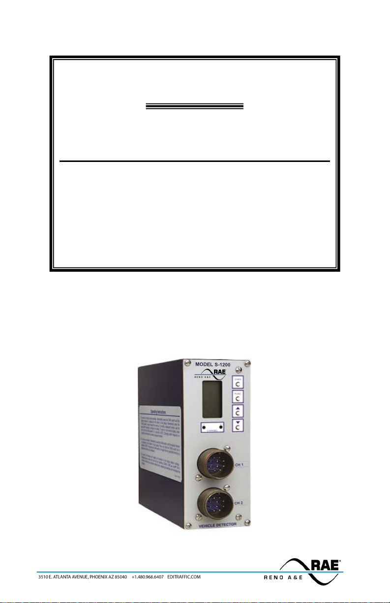
Model S-1200 Series
Operations Manual
Two Channel Menu Driven Programmable Inductive Loop
Detector
Built-in Loop Analyzer for Each Channel
This manual contains technical in formation for the
Model S-1200 Series Loop Detector
pn 889-1903-01 Revision: April 2020
Page 2

Page 3

THE FOLLOWING PRODUCT WAS DESIGNED, INSPECTED , TESTED AND
MANUFACTURED IN THE USA BY EBERLE DESIGN, INC. IN PHOENIX, ARIZONA.
INFORMATION CONTAINED HEREIN IS PROPR IETARY TECHNICAL INFORMATION OF
EBERLE DESIGN, INC. PUBLICATION, REPRODUCTION OR USE IN WHOLE OR PART IS
NOT PERMITTED EXCEPT UNDER TERMS AGREED UPON IN WRITING. ALL
REGISTERED TRADEMARKS OF EBERLE DESIGN INC. ARE UNDER
IT IS AN EBERLE DESIGN, INC. RECOMMENDATION THAT EACH UNIT BE TESTED
AT LEAST ANNUALLY TO ENSURE COMPLIANCE WITH FACTO RY
SPECIFICATIONS AND MEETS PROPER OPERATIONAL STANDARDS. THE
RESULTS OF THIS TESTING WILL BE DOCU M EN T ED .
© COPYRIGHT
MAINTENANCE NOTE
Page 4

Page 5

Model S-1200 Operations Manual
Table of Contents
Section 1 General Description .......................................................................................................... 1
Section 2 General Characteristics .................................................................................................... 3
2.1 Loop Frequency ..................................................................................................................... 3
2.2 Sensitivity .............................................................................................................................. 3
2.3 Presence / Pulse ..................................................................................................................... 3
2.4 Call Delay .............................................................................................................................. 3
2.5 Call Exte ns ion ........................................................................................................................ 3
2.6 Max Presence Timer .............................................................................................................. 3
2.7 End-Of-Green (EOG) ............................................................................................................. 4
2.8 Option 1: Loop Inductance Display ....................................................................................... 4
2.9 Option 2: Loop Inducatnce -∆L/ L Display ............................................................................. 4
2.10 Option 3: Call Ext ension Control ......................................................................................... 4
2.11 Option 4: Noise Filter .......................................................................................................... 4
2.12 Option 5: Phase Green Loop Compensation ........................................................................ 5
2.13 Option 6: Vehicle Counting Display .................................................................................... 5
2.14 Option 7: Vehicle Counting Loop Configuration ................................................................. 5
2.15 Option 9: Third Card Passage .............................................................................................. 6
2.16 Option 10: Direc tional Logic ............................................................................................... 7
2.17 Option 11: Audible Detect Signal ........................................................................................ 7
2.18 Option 12: Detector Disconnect .......................................... Error! Bookmark not defined.
Section 3 Specifications ..................................................................................................................... 9
3.1 Physical .................................................................................................................................. 9
3.2 Electrical ................................................................................................................................ 9
3.3 Operational ............................................................................................................................ 9
3.4 Table: Sensitivity, -∆L/L, and Response Time ..................................................................... 10
3.5 Table: Default Settings ......................................................................................................... 10
3.6 Table: Pin Assignments ....................................................................................................... 11
Section 4 User Interface ....................................................................... Error! Bookmark not defined.
Section 5 Installation and Set-Up ................................................................................................... 12
5.1 Program Mode Display Screens ........................................................................................... 13
5.2 Normal Mode Display Screens ............................................................................................ 17
5.3 Loop Fail Indications ........................................................................................................... 21
5.4 Setting Sensitiviy using the Bargraph .................................................................................. 22
5.5 Setting Sensitivity for Motorcycle Detection using the Bargraph ........................................ 23
5.6 Full Restore to Factory Default Settings .............................................................................. 23
5.7 Display Test ......................................................................................................................... 23
Section 6 Block Diagram ................................................................................................................ 24
Section 7 The o ry of Operation ....................................................................................................... 26
Section 8 Maintenance and Troubleshooting ................................................................................ 27
8.1 Troubles hooting Power Problems ........................................................................................ 27
8.2 Troubleshooting Initialization Problems .............................................................................. 27
8.3 Troubleshooting Loop Fail Problems ................................................................................... 28
8.4 Troubleshooting Intermittent Loop Fail Problems ............................................................... 29
8.5 Troubleshooting Intermittent Detector Lock-Ups ................................................................ 29
8.6 TroubleshootingDelay Problems .......................................................................................... 30
8.7 Things to Know About loops ............................................................................................... 30
Page 6

Page 7

Section 1 General Description
This Operation Manual was written for peop le installing, operating, and maintaining Reno A & E Model S1200 Series inductive loop vehicle detectors. The Model S-1200 is a two channel, shelf mount type, inductive
loop vehicle detector designed to meet or exceed NEMA Standards TS 1-1989.
The Model S-1200 incorporates a microco ntroller tha t monito rs and proce sses signals from two sepa rate loop /
lead-in circuits and two Phase Green Inputs. The microcontroller uses these inputs to d ete rmine how to control
the detector outputs. A Liquid C rysta l Display (LCD), t wo light e mitting diodes ( LEDs), and four front pa nel
pushbu tto ns a re us ed t o dis pla y and pr ogra m a ll det ect or funct io ns. Several diagnostic modes are available to
aid technicians and service personnel in troubleshooting detectio n proble ms.
The use of a LCD is what distinguishes this detector from that of other manufacturers. It allows more
information, never before available, to be displayed to the user d uring normal operation of t he detector. The
LCD makes it easy to view and adjust all programmable detector options and settings. It is no longer necessary
to check or change detector settings with DIP switches. An eight-segment bargraph at the top of the LCD can
be used to provide a graphical represe ntation o f the relative c hange of inducta nce as seen by the detector at the
current sensitivity level. The bargraph automatically takes into account loop size, loop inducta nce, number of
loops, number of turns, loop geometry, lead-in length, etc. The bargraph functions as a sliding scale that relates
to the programmed Sensitivity Level. The first (left-most) bargraph segment represents the minimum
inductance change necessary for the detector to output a call at the currently selected sensitivity level. Larger
inductance changes will indic ate more segments. Each addit ional segment indicates that the ne xt sensitivity
level has also been met or exceeded. When used in this manner, the bargraph provides an indication of whether
the sensitivity is set too high or too low, fac ilita ting the ideal setting of the sensitivity level.
All programmed settings a re stored in non-volatile memory and ca n only be changed by programming new
settings. Loss of power or a detector reset will not change any of the progra mmed settings. If a loop failure
occurs, the LCD w i l l displa y t he type of loop fa i l ur e a s L lo (for -25% change or shorted loop conditio ns) or L
hi (for +25% change or open loop condit ions). Each loop failure is counted and accumulated in the Loop
Failure Memory. The number of loop failures since the last detector reset or power interruption is very useful
information to have available during analysis of intermittent loop operation.
The Model S-1200 Series detector is a scanning detector. T he scanning operation sequentially activates the ON
and OFF cycle of each channel’s oscillator. Since only one channel’s loop(s) is (are) active at a given time,
crosstalk between adjacent loops connected to the same scanning detector is minimized. The Model S-1200
Series’ unique scanning process also disconnects the capacitors and dampens the oscillator during the OFF
cycle. This eliminates oscillation past the OFF point (ringing or deca y) every time the loop circ uit is scanned,
which can result in crosstalk. When operating in the Program Mode, t he Model S-1200 Series displays the r eal
time loop frequency reading for each cha nnel. The eight frequency settings can be incremented or decremented
to provide precise frequency readings, removing any guessw ork when cha nging frequ ency settings to eli minate
crosstalk. NOTE: Adjacent loops conne cted to different channels of a non-scanning detector or different
scanning detectors should be set to different frequencies with maximum separat ion.
The Reno A & E Model S-1200 Serie s uti lizes the fi rst ma jor in nova tion i n induc tive loop detectors since the
introduction of digital detecto rs. The pr ogra mming of a ll of t he detect or’s para meters with four nor mally ope n
pushbutton switches not only simplifies setup b y removing binary coded DIP switche s, but also increases the
reliability of the detector by eliminating the dependence on switch contacts d uring normal operation. The
detailed descriptions displayed on the LCD eliminate the interpretation of numerous LED flash rates to
determine the detector status. In add ition, the Model S-1200 offers the versatility of software control. Special
functions are possible with a simple change of the socket-mounted microprocessor. Special functions are
defined as unique options (e.g. Option 6, Option 12, etc.). Special option functions are activated t hrough the
use of the LCD menu option programming.
The Model S-1200 Series is comprised of the following detectors:
S-1200-R For NEMA TS 1-1989 app lications calling for a two channel, 120 volt
S-1200-R-12D For NEMA TS 1-1989 applications calling for a two channel, 12 volt
S-1200-R-240A For NEMA TS 1-1989 app lications calling for a two channel, 240 volt
S-1200-SS For NEMA TS 1-1989 app lications calling for a two channel, 120 volt
AC, she lf mo unt d et ec to r w it h re la y out p ut s a nd a n audible detect signal
(buzzer).
DC, she lf mo unt d et ec to r w it h re la y out p ut s a nd a n aud ib le d et ec t s ig na l
(buzzer).
AC, she lf mo unt d et ec to r w it h re la y out p ut s a nd a n a udib le det ec t s ig na l
(buzzer).
AC, shelf mount detector wit h solid state outputs and an a udible detect
signal (buzzer).
889-1903-01 Model S-1200 Operations Manual Page 1 of 28
Page 8

S-1200-SS-12D For NEMA TS 1-1989 applications calling for a two channel, 12 volt
S-1201-R For NEMA TS 1-1989 app lications calling for a two channel, 120 volt
S-1201-SS For NEMA TS 1-1989 app lications calling for a two channel, 120 volt
DC, shelf mount detector wit h solid state outputs and an a udible detect
signal (buzzer).
AC, shelf mount detector wit h True Count
TM
outp uts , re la y outp uts , a nd
an audible detect signal (buzzer).
AC, shelf mount detector wit h True Co unt
TM
outputs, solid state outputs,
and an audible detect signal (buzzer ).
889-1903-01 Model S-1200 Operations Manual Page 2 of 28
Page 9

Section 2 General Characteristics
2.1 LOOP FREQUENCY
There are eight (8) selectable loop frequency settings (normally in the range of 20 to 100 kilohertz) per
channel. The actual loop operating freq ue ncy is a function of the loop / lead-in network and the components of
the loop oscillator circuit. The digita l display of the actual loop operating frequency for each setting makes it
easy to quickly identify a nd eli minate cross talk in the most diffic ult to co nfigure intersecti ons . T he fr eq ue nc y
display is typically very stable when the loop is vacant and vehicles are not passing nearby the loops. If the
readi ng is vary i ng by more than ±1 in the last digit, this is an indicatio n of poss ible cros s talk betwee n loops.
2.2 SENSITIVITY
There are nine (9) selectable sensitivity levels per channel, plus Continuous-Call and Channel-Off. The
sensitivity levels are designed so that a one level increase actually d oubles the sensitivity and a one level
decrease halves the sensitivity. A unique bargraph displayed on the LCD makes it easy to quickly set
sensitivity at the ideal level for any loop / lead-in network configuration. (See Section 3.4 for actual detection
levels at eac h sensitivity level. )
C
ONTINUOUS-CALL: When set to t he Continuous-Call state, t he channel output is continuous ly in the Call
state regardless of the presence or absence of vehicles over the loop. The loop oscillator is disabled when in
the Cont inuous -Call state. This state is indicated b y CALL flashing on the LCD. Th is optio n is se lecte d
from the Sensitivity menu in Program Mode and is useful for checking controller response and other
troubleshooting activities.
C
HANNEL-OFF: When s et to the C han nel-O ff state, the channel outp ut is continuously in t he No Call state
regardless of the presence or absence of vehicles over the loop. The loop oscillator is disabled when in the
Channel-Off State. This state is indicated by OFF flashing o n the LCD. This opt ion is selected fro m the
Sensitivity menu in Program Mode a nd is useful for checking co ntroller respo nse and other tro ubleshootin g
activities.
2.3 PRESENCE / PULSE
One of two mutually exclusive modes of operation for each channel is available. Presence or Pulse mode is
toggled by momentarily pressing e ither the (UP) or (DOWN) button.
P
RESENCE MODE: Provides a call hold time of at least four minutes (regardless of vehicle size) and typically
one to three hours for an automobile or truck.
P
ULSE MODE: An output Pulse of 125 ±10 milliseconds duration is generated for each vehicle entering the
loop detection zone. Each detected vehicle is instantly tuned out if it remains in the loop detection zone
longer than two seconds. This enables de tection of subsequent vehicles entering the loop dete ction zone.
After each vehicle leaves the loop detection zone, the channel resumes full sensitivity within 0.5 seconds.
2.4 CALL DELAY
Each channel’s Call Delay is adjustable from 0 to 255 seco nds in one-second steps. Call Delay time s tarts
counting down when a vehicle enters the loop dete ctio n zone. The remaining C all D elay time is continuo usly
displayed on the LCD. Whene ver a Pha se Green Input (Call Delay Ove rride) signal (pin J o f the MS c onnector
of channel 1 or 2) is active, the Call Delay function for the channel is aborted and the Call De lay time is fo r ce d
to zero.
2.5 CALL EXTENSION
Each channel’s Call Extension is adjustable from 0 to 25.5 seconds in 0.1-second ste ps. Extension time starts
count ing down when the last ve hicle c lears t he loop detecti on zone. The re mainin g Call E xtensio n time is
continuously displayed on the LCD. Any vehicle e ntering the loop detection zo ne during the Call E xtension
time period causes the channel to return to the Detect state, and later, when the last vehicle clears the loop
detection zone, the full Call Extension ti me starts count ing down again. (See Option 3, Call Extension C ontrol,
for an a lternate mode of operation for C all Exte nsion.)
2.6 MAX PRESENCE TIMER
When activated, each channel’s Max Presence time r is adjustable from 1 to 999 seconds in one-second steps.
A setting of OFF turns the Max Presence timer off. The Max Presence function is used to limit presence time,
by automatically resetting the channel. If this function is enabled (ON), the Max Presence timer begins
889-1903-01 Model S-1200 Operations Manual Page 3 of 28
Page 10

counting down when a call is initiated and the remaining ti me is continuously displayed on the LCD. If the
loop becomes vacant before the Max Presence timer reaches zero, the call is dropped and no automatic reset
occurs. If the End-Of-Green (EOG) function is not enabled (OFF) and the call is s til l pres ent w hen the M ax
Presence timer reaches zero, the channel then is automatically reset. If the EOG function is enabled (ON) and
the call is still present when the Max Presence time r reaches zero, the channel enters a Wait state. The Wait
state continues until either the loop becomes vacant or the Phase Green Input signal for a channel (pin J of the
MS connector) transitions fro m green to not green with the call still prese nt. If the loop becomes vaca nt first,
the call is dropped and no auto matic reset occurs. If the Phase G ree n Input trans itions from green to not green
while a channel is in a Wait state, the channel is automatically reset. The signals on pin J of the MS connectors
of channels 1 and 2 are also called Call Delay Overrides. (See Section 3.2, Phase Green Input specification for
volta ge le ve ls . )
2.7 END-OF-GREEN (EOG)
Each c hannel’s EOG setti ng can be to ggled O N or OFF by momentar ily press ing eithe r the (U P) or
(DOWN) button. The EOG function is used to synchro nize resetting of a detector with the termination of the
associated phase green. The assumption is that this is the safest point in time to reset the channel. This
assumption is based on the premise that at the termination of the associated phase green, traffic should be
moving, and therefore, a reset would not result in the loss of a call when traffic comes to rest ove r the loop(s).
The EOG function is only available when the Max Presence function is set between 1 and 999 seconds. It is
not ava ila ble w he n the Ma x Pre se nce func tio n is OFF. Whe n t he EO G fu nct ion is e nab led (ON ), t he c hanne l
will automatically be reset at the same time the Phase Green Input signal (pin J of the MS connector)
transitions from the ON state to the OFF state, if the Max Presence Time has counted down to zero and is
resting in the wait state. The signals on pin J of the MS connectors of channels 1 and 2 are also called Ca ll
Delay Override. (See Section 3.2, Phase G reen Input specifications for voltage levels.)
2.8 OPTION 1: LOOP INDUCTANCE DISPLAY
Each channel’s Loo p I nductanc e D is p la y s e t t i ng c a n b e t o g g led O N o r OFF by mo mentari l y pr es sing eit her the
(UP) or (DOWN) button. When this opt ion is e nabled (ON ), the LCD displays the tota l loop ind uctance
(actual loop inductance plus actual lead-in inducta nce) i n mic ro henr ies f or lo op ind uc tanc e va lues in the ran ge
of 20 to 2500 microhenries. By recording the inductance of the loop / lead-in circuit when it is first insta lled,
the actual inductance can be compared to the expected inductance to help identify defective loop / lead-in
circuits. Loop / lead-in inductance can be easily estimated using the simple formulas included in Section 8.7 of
this manual. NOTE: Enabling t his option activates it for bot h channe ls. This optio n is auto matically disabled
15 minutes after activation or on loss of power.
2.9 OPTION 2: LOOP INDUCTANCE -∆L/L DISPLAY
Each cha nnel’ s Loop I nducta nce -∆L/L Display setting can be toggled ON or OFF by momentarily pressing
either the (UP) or ( D O W N) button. W he n t h is o pt ion is enab led (ON), t he LCD d isplays t he perce ntage
of induc t a nc e c hange (-∆ L/L value) during the Call state. To fac ilitate t he view ing of the maximu m amo unt of
change in the -∆L/L value while traffic is in motion over the detection zone, the channel holds the peak -∆L/L
value for a period of two seconds. NOTE: Enabling this option activates it for both channels. This option is
automatically disabled 15 minutes after activation or on loss of power.
2.10 OPTION 3: CA L L EXTENSION CONTROL
Each channel’s Call Extens ion Co ntro l set ting ca n be t oggl ed ON or OF F by mo me ntar ily pr essi ng ei ther t he
(UP) or (DOWN) button. Whe n this optio n is enable d (ON), the c hannel wi ll extend ca lls for the
progra mmed ext ensio n time only when the Phase Gre en Inp ut signa l (pin J of the MS connector) is active.
When th is opt ion is OF F, the channe l ex tend s ALL cal ls for t he pr ogra mmed exte nsio n time . The s igna ls o n
pin J of the MS connectors of channels 1 and 2 are also called Call Delay Overrides. (See Sect ion 3.2, Phase
Green Input specifications for voltage levels.)
2.11 OPTION 4: NOISE FILTER DISABLE
The detector’s Noise Filter Disab le setting can be toggled O N or OFF by mo mentarily pressing either the
(UP) or (DOWN) button. When Option 4 is enable d (ON), internal noise filtering is disabled thus providing
a faster response time. When this option is OFF, internal noise filtering is utilized. When the detector is used
in speed and/or occupancy applicatio ns, the noise filter should be disabled ( i.e. Option 4 ON) to provide the
most accurate data possible. It is recomme nded that this option not be activated. The factory default setting of
OFF provides stable operation in high cross talk environments. NOTE: Enabling this option activates it for
both channels. Changing the setting of this feature will reset both detector channels.
889-1903-01 Model S-1200 Operations Manual Page 4 of 28
Page 11

The Loop Fail Count is not reset w he n t he setting of Option 4 is changed. Also, changing the setting of Option
4 will not cause the prior Loop Fail indication to cease (see Section 5.3, Loop Fail Indications).
2.12 OPTION 5: PHASE GREEN LOOP COMPENSATION
Each channel’s Phase Green Loop Co mpensation setting ca n be toggled ON or O FF by momentarily p ressing
either the (UP) or (D O WN ) b ut to n. Whe n O pt io n 5 is e nab le d (O N ), no rma l loo p c o mpe ns at io n is us ed
until the Phase Green Input signal (pin J of the MS connector) becomes active. Once the Phase Green Input
signal is active, the channel desensitizes the loop. Maximum desensitization is 0.05% (-∆L/L). This
desens it iza t io n tu nes o ut s ma ll cha n ges , s uc h as adjacent lane pickup, therefore minimizing the chance of max
timing an empty lane. Note: A small motorcycle may also be tuned out in a short period of time following the
start of Phase Green. This option is useful in minimizing false detect ion resulting from adjacent lane pickup
when a c ha nne l mu st be ru n w ith a h igh s ens it iv it y se tt in g. W he n Op t ion 5 is no t ena b led ( O FF ), no r ma l lo op
compensation is use d.
2.13 OPTION 6: VEHICLE COUNTING DISPLAY
Option 6 has two parameters, Option 6.0 and Option 6.1.
When Option 6.0 is enabled (ON) for a c hannel, the normal operating display for that channel is replaced
with the accumulated vehicle count. The unit is capable of accumulating 65,535 vehicle counts before
rolling over to zero. T he display will s how the hundreds, tens, and ones d igits until the accumulated co unt
exceeds 999. At this point t he disp lay will a lternate betwee n the ten tho usands a nd thousa nds d igits a nd the
remaining three digits for hundreds, tens, and ones.
When the detector is first powered up, the detector enters a training mode. Operation in the training mode is
indicated by the accumulated vehicle co unt flashing on the LCD. Training mode enables the detector to
identify what degree of inductance change a typical vehicle causes as it is detected. When the training
period is complete, the flashing display of the accumulated vehicle count on the LCD will cease and the
LCD will show the actual accumulated vehicle count. The most accurate vehicle counts are obtained once
the detector is operating in this mode, i.e. after the training period is complete.
Option 6.1 is used to reset the accumulated vehicle co unt for the selected channel. When Option 6.1 is
changed from the OFF state to the ON state, the accumulated vehicle count for the selected channel is reset
to zero. Option 6.1 will always be in the OFF state when first viewed. The accumulated vehicle count is
also cleared by loss of power.
2.14 OPTION 7: VEHICLE COUNTING LOOP CONFIGURATION
This feature is only available on the True CountTM version of the Mod el S-1200 detector (S-1201). The
detector’s Vehicle Counting Loop Configuration se tt ing ca n be set fro m 01 to 04 for each channel. This setting
should indicate the number of loops installed in a single lane. The setting 01 would indicate a single loop.
This could be a single 6 ΄ x 6΄ or a long loop such as a 6΄ x 50΄ Quadrupole
indicate the number of 6΄ x 6΄ loops installed in a single lane of traffic.
Several factors can influence the accuracy achieved with this detector:
1. Lanes per Detector - The detector was designed to be used in applications where each channel is used to
count vehicles in a single lane o f traffic. It is not intended to be used in applications where it is
necessary to count cars across multiple lanes of traffic.
2. Loop Geometry - In t he mu l t iple loo p s e t t i n gs (02-04), all l oops must be of the same configuration, i.e.
the same number of turns a nd t he same size. Also, all loops must be equally spaced. The idea l spac ing
for 6 ft. by 6 ft. loops is 15 ft. center to center or 9 ft. spacing between loop edges. Further, multiple
loops should always be wired in a ser ies network. This is important to e nsure that a vehicle passing
over the group of loops causes the sa me amount of ind uctance change in e ach loop. I n the single loop
setting (01), square or rectangular co nfigurations will give slightly better results than Quadrupo le
configurations.
3. Loop Placement - Loops should always be placed in the center of the traveled lane. Loops should
extend out in front o f the stop bar. For t urning move ments, loops should not e xtend so far out in front
of the s to p bar that exitin g vehicles w o u ld e x it mo re out of t he side of t he lo o p t ha n out the f ro nt o f t he
loop. If the detector is operating in the multiple loop mode and other move ments of traffic c lipping the
front edge of the loop are a concern, the detector will only count vehicles that cross more than one loop.
It will ignore all vehicles that clip a single loop.
4. Sensitivity Setting - The se nsitivit y should be set so that a single pass enger vehicle in the detection
zone creates a seven dot deflection on the bargraph on the LCD.
TM
. The remaining three settings
TM
889-1903-01 Model S-1200 Operations Manual Page 5 of 28
Page 12

Loop B
Loop A
Whenever the detector is powered up, the sensitivity is changed, or the loop configuration is changed, the
detector will enter the tra ining mode. While in this mode, the detector is evaluating individual vehicles passing
through the detection zone. T his means that no other vehicle can occupy any part of the detection zone while a
vehicle passes through. The detector will accumulate counts during the training period. Optimal count
accuracy will occur after the tra ining period is complete. Depending on traffic density a nd the length of
detection zone, this training period could take many hours. We recommend installing the detector the day
before actual vehicle cou nts are to be co llected. This w ill allow s ufficient time for the detecto r to train itse lf.
The training period is necessary to ensure that the detector can adjust itself to the exact particulars of a given
loop installation.
The vehicle counting feature cannot be turned off and is active regardless of any other features that have been
enabled. Even if other features (Delay, Third Car Passage, Directio nal Logic, or Detector Disconnect) would
cause the normal detector output to be in the No Call state, the vehicle counting feature will still operate
correctly.
2.15 OPTION 9: THIRD CAR PASSAGE
Each channel’s Third Car Passage setting can be toggled ON or OFF by momentarily pressing either the
(UP) or (DOWN) button. Option 9 is a paired channel option. This means that it takes two channels to
implement the feature. Therefore, when this option is toggled ON or OFF in one channel, its paired channel is
also set to the same state. In the Model S-1200, Channel 1 is paired with C hanne l 2. NO TE: Opt ion 9 is
mutua lly exclusive with Option 10. Turning ON one option will automatically turn OFF the other option.
When Op tion 9 is enab led (ON ), the o utput o f the tw o paire d chan nels ar e logica lly AN Ded to gether . This
means t hat while the loops for both o f the paired c hanne ls are occ upied, a ca ll will be outp ut on both c hannels.
While only one channel is occupied, or neither channe l is occupied, a call will not be outp ut for either channe l.
The firs t channel w ith detecti on will e nter a pending state while waiting for detection on the other paired
channel. While in the pending state, the LCD w ill s how Pnd on the display.
This feature is intended to be used in Protected / Permissive left tur n situations. The expected insta llation is a
stop bar loop for the left turn lane connect ed to one channel, a queue detect ion loop (with a small amount o f
delay t ime pro gra mmed ) fo r the lef t tur n la ne c onne cte d to t he o the r cha nne l, a nd t he o utpu t o f eit her c han ne l
connected to the Vehicle Call input for the protected movement of the traffic controller.
Basic Insta llatio n - Loop A is the Queue Detection loop
and Loop B is the Stop Bar loop.
Car enters Loop A - No ca ll is o utp ut.
Car proceeds to Loop B - No call is output.
Additional cars enter the left turn lane - When the back of
the queue reaches Loop A while a car is s till over Loop B,
a call will be output.
When T hird C ar Pa ssage is t urned o n, a s the first vehic le e nters the le ft tu rn la ne it will d rive o ver the q ueue
detection loop. Since there is no vehicle over the stop bar loop, there is no call output gene rated. The vehicle
advances to the stop bar loop. Still, no output is generated because there is no vehicle over t he queue detection
loop. If the vehic le tra ffi c in t he left t urn lane backs up to the que ue detect ion loop, then t he stop bar loop a nd
the queue detection loop will both be occupied at the same time. This will cause the detector to generate a call
to the traffic controller to service the protected movement for the le ft t u r n. T his should help clea r t he q ueue of
vehicles in the left turn lane. The spacing between the stop bar loop and the queue detection loop controls the
size of the queue needed to generate a call to the protected movement of the controller. The de la y t ime o n the
Queue Detection loop should be sufficiently long that vehic les driving over this loop t o enter the queue do not
generate a call.
889-1903-01 Model S-1200 Operations Manual Page 6 of 28
Page 13

Loop B
Loop A
Basic Ins tallat ion
Car enters Loop A - No call is output
is
Car proceeds to Loop B
Car proceeds to Loop A
2.16 OPTION 10: DIRECTIONAL LOGIC
Each channel’s Directional Logic setting can be toggled ON or OFF by moment arily pr essing e ither t he
(UP) or (DOWN) button. Option 10 is a paired c hannel option. This mea ns that it takes two channels to
implement the feature. Therefore, when this option is toggled ON or OFF in one channel, its paired channel is
also set to the same state. In the Model S-1200, Channel 1 is paired with Channel 2. NO TE: Option 10 is
mutua lly exclusive with Option 9. Tur ning ON one option will automatically turn OFF the other option.
When Op t io n 10 is e nab le d ( ON ), d ire ct io na l l o gic is enabled. Directional logic starts with a detection on one
channel. This channel will go into the pending state, display Pnd on the LCD, and N OT outp ut a call. Whe n
both of the paired cha nnels have de tection, the last c hannel to ha ve detection will output a call until the
detection for the last channel ends, even if the detection ends for the first channel. None of the timing
functions of the first channel with a detection will time (Delay, Extension, Max Presence, and Detector
Disconnect) and the first channel will always operate in the Presence Mode regardless of the programming of
the channel.
This feature is intended to be used in parking lot applicat ions where vehicles can enter or exit from the sa me
lane, freeway r amps f or wron g way det ection, and le ft turn lanes whe re ot her move ments i n the inte rsec tion
tend to clip the detection zone of the left turn lane. The expected installation is two loops, one after the other in
the same lane, spaced anywhere from slightly overlapping to 6 feet apart. NOTE: Contact a Field Engineer
at Reno A & E regarding proper loop configurations and spacing for specific app licati ons.
When D irect iona l Det ect ion is tur ned o n, a ve hic le e nteri ng the firs t lo op wi ll ca use that c han nel t o ente r the
pending state. As the vehicle enters the se cond loop while still occupying the first loop, the second channel
will enter the Call state w hile the first cha nnel rema ins in the pe nding state. A call is neve r output on t he first
channel with a detection. Under normal conditions both outputs can never be on at the s ame time. However, if
one of the loops fail, both outputs will come on and stay on until the failure is corrected.
Call is output o n C hannel B
2.17 OPTION 11, AUDIBLE DETECT SIGNA L
Each channel’s, Audible Detect Signal setting can be toggled ON or OFF by momentarily pressing either the
(UP) or (DOWN) button. Only one channel can be t urned ON at a time. Turning this opt ion ON for one
channe l a ut oma t ica ll y t urns i t O FF f or t he ot he r c ha nne l. Whe n t his op t io n is ena bl e d (O N), a n a ud ible s ig nal
will be activated whenever the detection zone for the selected channel is occupied. The audible signal indicates
actual o ccupa ncy o f the lo op det ectio n zone. Timin g and d isco nnect functi ons ha ve no e ffect o n the a udible
signal. This feature allows a technic ian to watch the detection zone on the street and confirm correct detector
operation without having to look at the det ector d isplay as w ell. NOTE: This o ption is auto matically disab led
15 minutes after activation or on loss of power.
2.18 OPTION 12: DETECTOR DISCONNECT
Each channel’s Detector Disconnect setting can be toggled ON or OFF and the Extension timer toggled
betwee n ON and OFF by moment arily press ing either the (UP) or (DOWN) button. The Detector
Disconnect feature requires that the P hase Green Input for the channel be connected to the proper controller
phase. Whe n the Phas e G ree n Inp ut is not ac tive, the c ha nne l sha ll op era te no rma ll y. W hen t he Pha se G ree n
Input is active, the extens ion timer will start to c ount down at the end of each de tection. If this timer reaches
zero be fore the ne xt detectio n, this cha nnel will no l onger outp ut a call unt il the Phase Green Inp ut is not
active. Since the extension timer is used as a disconnect timer while in this mode, two diffe rent disconnect
types are available:
889-1903-01 Model S-1200 Operations Manual Page 7 of 28
Car enters Loop B - No cal l
Call is output o n C hannel A
Page 14

ion Zone
Phase Green
Output w/ 12.1 Off
Output w/ 12.1 On
This example assumes an extension time of 2 seconds. The dott ed lines show where disconnect would occur.
Seconds 0 5 10 15 20 25 30 35 40 45 50 55
Option 12.1 OFF: Extension timing still oc curs and the extension timer is a lso the disconnect ti mer during
phase green. This w ill cause the ca ll output to re main in the Ca ll state until disco nnect occurs. This may
allow t he us e r to us e ga p t imes appropriate for the advance loops witho ut consider ing the e ffects on t he stop
bar loops.
Optio n 12.1 ON: Exte nsion t i mi n g is disa b le d and the e xt ension t i me r is us e d a s t he disconne c t t i mer. Th is
will cause the call output to follow the occupation of the loop detection zone until disconnect occurs.
This feature is intended to be used in applications where a loop at the stop bar is not needed after any waiting
queue in the associated traffic lane is moving during the green phase. The expected insta llation is a stop bar
loop (typically a 20΄ to 30΄ long detection zone) and an advance detection loop (typically a 6΄ long detection
Detect
Phase Green is the state of the light (actual Phase Green Input is i nv er ted).
zone) for a single traffic lane. This feature pro vides a means for keeping the stop bar loop from placing ca lls to
the traffic controller a fter the stop bar loop has served its intended purpose d uring the beginning period of the
associated green phase. The channel connected to the stop bar loop would have the Detector Disconnect
feature turned ON and have a programmed extension time tha t functions as the disconnect time. The channel
connected to the advance detection loop would be programmed as normal.
When the D e t e c to r Discon nec t fe a t ure is t u r ned O N a nd t he s i g na l is no t gre e n, the cha nnel outp ut s calls to t he
traffic contro ller as usual. When the signal turns green, vehicles begin to move and eventually the stop bar
detection zone is cleared. At the time that the stop bar detection zone is cleared the disconnect timer begins to
count down. If another vehicle e nters the s top bar detection zone before the disconnect timer reaches zero, the
channel outputs the new call to the traffic controller and the disconnect timer is reset to its initial value. Once
the stop bar detection zone remains clear for a time equal to the programmed disconnect time, the detector
channel is disabled a nd will not generate any further ca lls to the traffic controller until after the green has
terminated. When the stop bar detect ion loop is disabled, the green p hase can only be extended by ve hicles
detected by the advance detection loop. NOTE: The disconnect timer will always time an initial gap each time
that the phase turns green. If Opt ion 12.1 is OFF, the channel will generate a n output for the specified
extension time at the start of each green phase.
889-1903-01 Model S-1200 Operations Manual Page 8 of 28
Page 15

Section 3 Specifications
3.1 PHYSICAL
WEIGHT: 34 oz. (963.9 gm).
S
IZE: 6.45 inches (16.38 c m) high x 2.50 inches (6.35 c m) wide x 6.35 inches (16.13 c m) deep (excluding
connectors). Connectors add .675 inch (1.71 cm) to depth measurement.
O
PERATING TEMPERATURE: -40° F to +180° F (-40° C to +82° C).
C
IRCUIT BOARD: Printed circuit boards a re 0.062 inch t hick FR4 material w ith 2 oz. c opper on both s ides and
plated through holes. Circuit board and components are conformal coated with polyure thane.
C
ONNECTOR: Two (2) MS3102A-18-1P. See Section 3.6 for pin assignments.
3.2 ELECTRICAL
POWER: 89 to 135 VAC, 50/60 Hz, 6 Wat ts maximum (120 volt AC models). 180 to 270 V AC, 50/60 Hz, 6
Watts maximum (240 volt AC models). 9.6 to 14.4 VDC, 250 mA maximum, 3.8 Watts maximum (12 volt
DC models).
L
OOP INDUCTANCE RANGE: 20 to 2500 micro henries w ith a Q factor of 5 or greater.
L
OOP INPUTS: Transformer isolated. The minimum capacitance added is 0.068 microfarad.
L
IGHTNING PROTECTION: Meets and/or exceeds all applicable NEMA TS 1-1989 specifica tions for transient
voltage protection.
R
ESET: Meets and/or exceeds NEMA TS 1-1989 detector specifications. The detector can be reset by
removing and reapplying power or by changing the setting o f Option 4 (Noise Filter Disable). Each detector
channel can be independently reset by pressing the CHAN butto n until the desired channel is se lected, then
pressing and holding the CHAN button for three seconds. Also, changing either the sensitivity or loop
frequency of a channe l will reset that channel.
P
HASE GREEN INPUTS: Also known as Call De lay Overrides. Meets and/or exceeds all NEMA TS 1-1989
requirements. Application of a high state voltage (89 to 135 VAC) to pin J of the MS connector of channel 1 or
2 causes the delay timer for the channel to abort the delay timing functio n and also pro vides control for Pha se
Green Loop Compensation, Max Presence Timing (End-of-Green), Extension Timing, and Detector
Disconnect, if the features are progra mmed .
R
ELAY RATING: The relay contacts are rated for 6 Amps maximu m, 150 VDC maximum, and 180 Watts
maximum switched power.
S
OLID STATE OUTPUT RATING: Optically isolated. 30 VDC maximum collector (drain) to emitter (source).
100 mA ma xi mu m s at ur at io n c urr e nt. 2 V D C max imu m tra ns is to r s a tur at io n v o lta ge. The output is protected
with a 3 3-volt Zener diode connected between the collector (drain) and emitter (s o urc e).
3.3 OPERATIONAL
DISPLAY: The LCD backlighting illuminates whenever any pushbutton is p ressed. The backlighting will
extinguish 15 minutes after the last pushbutton pre ss.
D
ETECT INDICATOR: Each channel has a super bright, high intens ity, red light emitting diode (LED) to ind icate
a Call Output, Delay Timing, Extens ion Timing, Pending State, or Failed Loop condition.
R
ESPONSE TIME: Meets or exceeds NEMA TS 1-1989 response time specifications. (See Sectio n 3.4 for actual
response times.)
S
ELF-TUNING: The detector automatically tunes and is operational within two seconds after application of
power or after being reset. Full sensitivity and hold time require 30 seconds of operation.
E
NVIRONMENTAL & TRACKING: The detector is fully se lf-compensating for environmental changes and loop
drift o ver the f ull temperature r ange and the ent ir e loop inductance range.
G
ROUNDED LOOP OPERATION: The loop isolation transformer allows operation with poor quality loops (w hich
may include one short to ground at a single point).
L
OOP FEEDER LENGTH: Up to 5000 feet (1500 m) maximum with proper feeder cable and appropriate loops.
889-1903-01 Model S-1200 Operations Manual Page 9 of 28
Page 16

Respons e Time
(Option 4 O FF)
Respons e Time
(Option 4 ON)
OFF
-------
-------
-------
1
0.64%
133 ±27 ms
20 ±4 ms
2
0.32%
133 ±27 ms
20 ±4 ms
3
0.16%
133 ±27 ms
20 ±4 ms
4
0.08%
133 ±27 ms
20 ±4 ms
5
0.04%
133 ±27 ms
20 ±4 ms
6
0.02%
133 ±27 ms
27 ±5 ms
7
0.01%
133 ±27 ms
42 ±8 ms
8
0.005%
133 ±27 ms
72 ±14 ms
9
0.0025%
133 ±27 ms
133 ±27 ms
CALL
-------
-------
-------
it by two, then add these times together.
Function
Channel 1
Channel 2
Frequency 3 7
Sensitivity 6 6
Delay Time 0 0
Extens ion Time 0 0
Max Presence Time
OFF
OFF
Presence / Pulse Mode
Presence
Presence
EOG
OFF
OFF
Option 1 - Loop Inductance Display
OFF
OFF
Option 2 - Loop Inductance -∆L/L Display
OFF
OFF
Option 3 - Call Extension Control
OFF
OFF
Option 4 - Noise Filt er Disable
OFF
OFF
Option 5 - Phase Green Loop Compensation
OFF
OFF
Option 6.0 - Display Vehicle Co u nt
OFF
OFF
Option 6.1 - Reset Vehicle Count
OFF
OFF
Option 7 - Number of Loops
04
04
Option 9 - Third Car Passage
OFF
OFF
Option 10 - Dire c tional Logic
OFF
OFF
Option 11 - Audible Detect Signal
OFF
OFF
Option 12.0 - Detector Disconnect
OFF
OFF
Option 12.1 - Detector Disconnect Type
OFF
OFF
LOOP (FAIL) MONITOR: If the total inductance o f the channe l’s loop inp ut network goes out of t he range
specified for the detector, or rapidly change s by more than ±25 %, the channel will immediate ly enter the FailSafe mode and display LOOP FAIL on the LCD. The type of loop failure will a ls o b e d is played a s L lo (for 25% change or shorted loop conditions) or L hi (for +25% change or open loop conditions). This will continue
as long as the loop fault exists. However, if the detector is reset, or power is momentarily lost, the detector
will retune if the loop inductance is within the acceptable range. If any type of loop failure occurs in one
(or more) loop(s) in a group of two or more loops wired in parallel, the detector will not respond with a
Fail-Safe output f ol lowing any type of reset. It is essential that m ultiple loops wired to a common
detector channel always be wired in series to ensure Fail-Safe operation under all circumstances. At the
time of a loop failure, the channel’s LED will begin to flash at a rate of three flashes per second. The LED will
continue this display pattern unt il t he channel is manually reset or power is removed. If the loop self-heals, the
LOOP FAIL message on the LCD will e xtinguis h and the c hannel will res ume operation in a normal manner;
except the LED will continue the three flashes per s econd display pattern, thus providing an alert that a prior
Loop Fail condition has occurred. Each loop failure for the channel is counted and accumulated into the Loop
Fail Memory. The total number of loop failures written into the Loop Fail Memory (since the last power
interruption or manual reset) is viewed by stepping through the cha nnel’s functions in Progra m Mode until the
LOOP FAIL messa ge is displayed.
3.4 TABLE: SENSITIVITY, -∆L/L, AND RESPONSE TIME
Sensitivity -ΔL/L
NOTE: Entries in this table are based on the assumption that both channels are set to the same sensitivity. To approximate
response time for a detector with the channels set to different sensitivities, look up the response time for each channel and divide
Noise Filter Enabled
Noise Filter Disabled
3.5 TABLE: DEFAULT SETTINGS
889-1903-01 Model S-1200 Operations Manual Page 10 of 28
Page 17

Pin
Function
Pin
Function
Power, Neutral, 120 / 240 VAC (AC Models)
12 VDC Common (DC Models)
B
Channel 1 Output, Relay Common
B Channel 2 Output, Relay Common
Power, Line, 120 / 240 VAC (AC Models)
+12 VDC (DC Models)
D
Channel 1 Loop Input
D Channel 2 Loop Input
E
Channel 1 Loop Input
E Channel 2 Loop Input
F
Channel 1 Output, Relay Normally Open
F Channel 2 Output, Relay Normally Open
Channel 1 Output, Relay Normally Closed
Channel 1 Output, Relay Normally Open
Channel 2 Output, Relay Normally Closed
Channel 2 Output, Relay Normally Open
H
Chassis Ground
H Chassis Ground
No Connection
Channel 1 Output, Relay Common
No Connection
Channel 2 Output, Relay Common
J
Channel 1 Phase Green Input (Delay Override)
J Channel 2 Phase Green Input (Delay Override)
NOTE: Relay contact states are shown with power applied, loop(s) connected, and no vehicle(s) present.
Pin
Function
Pin
Function
Power, Neutral, 120 / 240 VAC (AC Models)
12 VDC Common (DC Models)
B
Channel 1 Output, Emitter (Source)
B Channel 2 Output, Emitter (Source)
Power, Line, 120 / 240 VAC (AC Models)
+12 VDC (DC Models)
D
Channel 1 Loop Input
D Channel 2 Loop Input
E
Channel 1 Loop Input
E Channel 2 Loop Input
F
Channel 1 Output, Collector (Drain)
F Channel 2 Output, Collector (Drain)
No Connection
Channel 1 Output, Collector (Drain)
G No Connection
Channel 2 Output, Collector (Drain)
H
Chassis Ground
H Chassis Ground
No Connection
Channel 1 Output, Emitter ( Source)
I No Connection
Channel 2 Output, Emitter ( Source)
J
Channel 1 Phase Green Input (Delay Override)
J Channel 2 Phase Green Input (Delay Override)
3.6 TABLE: PIN ASSIGNMENTS
RELAY OUTPUTS
C
HANNEL 1 CONNECTOR CHANNEL 2 CONNECTOR
A
C
G
Model 1201 - True CountTM
I
Model 1201 - True CountTM
A No Connect ion
C No Connection
G
Model 1201 - True CountTM
I
Model 1201 - True CountTM
SOLID STATE OUTPUTS
C
HANNEL 1 CONNECTOR CHANNEL 2 CONNECTOR
A
C
G
Model 1201 - True CountTM
I
Model 1201 - True CountTM
A No Connection
C No Connection
Model 1201 - True CountTM
Model 1201 - True CountTM
889-1903-01 Model S-1200 Operations Manual Page 11 of 28
Page 18

FUNC
CHAN
1
2
CHANNEL
MODEL S
VEHICLE DETECTOR
CH 1
CH 2
-∆L/L
FREQ
LOOP FAIL
OPTIO
MAX
OFEOSCANNI
EXTENSION
SENSITIVITY
DELA
PULS
SECONDS
ON
Seven Segment Display
Vehicle Count
Parameter Description
Function Select Pushbutton
Channel Select Pushbutton
Press and Hold for Three
UP Pushbutton
Bargraph
Numbered Loop Symbols
LED Indicators
DOWN Pushbutton
MODEL S-1200
Section 4 User Interface
• Vehicle Signal Strength
• Frequency Setting
• Parameter Values
• Timer Countdown
• Frequency Reading
• Inductance Value
• -∆L/L Value
• Pending Call State
• Type of Loop Failure
• L hi = Open Loop or L
High
• L lo = Shorted Loop or L
Low
•
• Name of Parameter
• Timer in Operation
• Channel Displayed
• Flashing = Program Mode
• Call
• Delay Time in Progress
• Extension Time in Progress
• Pending Call State
• Loop Fault has Occurred
• Change Displayed Channel
Press and Release
• Exit Program Mode
Press and Hold for One Second
• RESET Channel
Seconds
• Press Momentarily to Enter
Program Mode and to Step
Through Parameters
• Increments Values
• Toggles ON and OFF
• Decrements Values
• Toggles ON and OFF
NOTE: There are no internal switches or jumpers to set.
889-1903-01 Model S-1200 Operations Manual Page 12 of 28
Page 19

FREQ KHZ
1
©
SENSITIVITY
1
©
©
PULSE
1
Section 5 Installation and Set-Up
The detector has no DIP switches or jumpers to configure. Connect the detector to an appropriately wired
harness and apply power. If the detector is not new from the factory, it may be advantageous to reset the
detector back to the factory defaults to a void having to check every setting for each channel. To reset the
detector to factory de fault, p ress a nd ho ld a ll four p ushb utton s w itches s imulta neous ly for five se co nds. W hen
all four buttons are depressed, the display will start counting down from five (5). When the countdown reaches
zero (0), releasing the pushbuttons w ill reload the factory defaults and reset both channels.
All operating parameters can be adjus ted from the front panel. The detector continues to operate norma lly
while it is in the Program Mode. The value currently displayed is always the actual value being used.
Example: If you are changing the delay time, t he t ime d isplayed at the instant that a vehicle entered the
detection zone for that channel would be the value used for the delay timer.
Pressi ng the FU NC butto n enters the Prog ram Mode . The FUN C button has an aut o repea t functi on. This
allows quick navigation to the desired parameter. The FUNC button only moves forward through all of the
parameters. There is no way to move backwards through the parameters.
While viewing any parameter, pressing the CHAN button will display the same parameter for the next channel.
The currently selected c hannel is indicated at the b ottom o f the LCD. Press ing and hold ing the C HAN b utton
for one second will exit the Program Mode and return to the Normal Mode.
Pressi ng a nd ho ldi ng e it he r t he (UP) or (DOWN) button will ca use the value to change rap idly unt il the
button is released.
5.1 PROGRAM MODE DISPLAY SCREENS
PARAMETER ...................Frequency.
S
ETTINGS ........................Eight (8) Selections - 1 to 8.
S
ETTING DISPLAYED ......Bargraph indicates settings from 1 (left) to 8 (rig ht).
7
SEGMENT DISPLAY ......Actual Frequency of the loop circuit. Typically 20. 0 to 99. 9
D
EFAULT SETTING..........Channel 1 = 3, Channel 2 = 7.
E
XAMPLE ........................Frequency setting 4 is selected for channel 1. The loop
N
OTES .............................Changi ng the fr eq ue nc y w ill res e t t he c han ne l. A n uns tab le
P
ARAMETER ...................Sensitivity.
S
ETTINGS ........................11 Selections - 1 to 9, OFF, or CALL.
S
ETTING DISPLAYED ......7-segment display will sho w the currently selected setti ng.
7
SEGMENT DISPLAY ......Currently selected Sensiti vity.
D
EFAULT SETTING..........6 fo r bot h c hanne ls.
E
XAMPLE ........................Sensitivity 5 is selected for channel 1.
N
OTES .............................Changing the sensitivity will reset the channel. If the
P
ARAMETER ...................Presence / Pulse Mode.
S
ETTINGS ........................Presence or Pulse.
S
ETTING DISPLAYED ......The word PRESENCE or PULSE will be displayed.
7
SEGMENT DISPLAY ......Blank.
D
EFAULT SETTING..........Presence for both channels.
E
XAMPLE ........................Pulse Mode is selected for channel 1.
N
OTES .............................If the channel is in the call state when this parameter is
kilohertz.
frequency is 34.9 kHz.
frequency display varying more than ±0.2 kilohertz may
indicate loop crosstalk or other interference.
channel is in the call state when viewing this parameter, the
bargra ph wil l show t he stre ngth o f vehic le c alls so that t he
correct sensitivity can be verified from this screen.
changed, the change will not take effect until the detection
zone is empty or the channel is re set.
889-1903-01 Model S-1200 Operations Manual Page 13 of 28
Page 20

©
DELAY
SECONDS
1
EXTENSION
SECONDS
1
©
MAX PRESENCE
SECONDS
1
©
EOG
1
ON © OPTION
1
ON © OPTION
OFF
1
©
ARAMETER ...................Delay.
P
S
ETTINGS ........................256 Selections - 0 to 255 Seconds in one-se cond steps.
S
ETTING DISPLAYED ......7-segment display will sho w the currently selected setti ng.
7
SEGMENT DISPLAY ......Currently selected Delay time in seconds.
D
EFAULT SETTING..........0 seconds for both channels.
E
XAMPLE ........................Delay of 10 seconds selected for channel 1.
N
OTES .............................If the channel’s detection zone is occupied when this
P
ARAMETER ...................Extension.
S
ETTINGS ........................256 Selections - 0 to 25.5 Sec onds in 0.1-second steps.
S
ETTING DISPLAYED ......7-segment display will show the currently selec ted setting.
7
SEGMENT DISPLAY ......Currently selected Extension time in seconds.
D
EFAULT SETTING..........0 seconds for both channels.
E
XAMPLE ........................Extension of 2.5 seconds s elected for channel 1.
N
OTES .............................This parameter will hold the Disconnect timer value if
P
ARAMETER ...................Max Presence.
S
ETTINGS ........................1000 Selections - 1 second to 999 seco nds or O FF.
S
ETTING DISPLAYED ......7-segment display will sho w currently selected s ettin g.
7
SEGMENT DISPLAY ......Currently selected Max Presence time in seconds.
D
EFAULT SETTING..........OFF for both channels.
E
XAMPLE ........................M ax Prese nce is turned OFF f or chan nel 1.
N
OTES .............................If the channel’s detection zone is occupied when this
P
ARAMETER ...................EOG (End Of Green).
S
ETTINGS ........................ON or OFF.
S
ETTING DISPLAYED ......The word ON or OFF will be displayed.
7
SEGMENT DISPLAY ......Blank.
D
EFAULT SETTING..........OFF for both channels.
E
XAMPLE ........................EOG is turned ON for channel 1.
N
OTES .............................This parameter is only displayed if the Max Presence
P
ARAMETER ...................Option 1 (Loop / Lead-In Induc tance Display).
S
ETTINGS ........................ON or OFF.
S
ETTING DISPLAYED ......The word ON or OFF will be displayed.
7
SEGMENT DISPLAY ......The number of this option.
D
EFAULT SETTING..........OFF for both channe ls.
E
XAMPLE ........................Option 1 is turned ON for all channels
N
OTES .............................This option is a detector wide setting. Ch anging it for one
ARAMETER ...................Option 2 (Perce nt age of Inducta nce change, -∆L/L).
P
S
ETTINGS ........................ON or OFF.
S
ETTING DISPLAYED ......The word ON or OFF will be displayed.
7
SEGMENT DISPLAY ......The number of this option.
D
EFAULT SETTING..........OFF for both channels.
E
XAMPLE ........................Option 2 is turned OFF for all channels.
N
OTES .............................This option is a detector wide setting. Ch anging it for one
parameter is changed, the change will not take effect until
the detection zone is empty or the channel is reset.
Option 12.0 is ON and extension will not be added to a
vehicle call if Option 12.0 and 12.1 are ON.
parameter is changed, the change w ill not take effect until
the detection zone is empty or the channel is reset.
settin g for t he cha nnel ha s been p rogra mmed w ith a va lue
between 1 and 999. Operation of this feature requires that
the Phase Green Inputs be correctly connected to the
controller phase green circu i try.
channel changes it for both channels. This option will
automatically turn off 15 minutes after being activated or on
loss of power.
channel changes it for both channels. This option will
automatically turn off 15 minutes after being activated or on
loss of power.
889-1903-01 Model S-1200 Operations Manual Page 14 of 28
Page 21

OPTION
1
ON © OPTION
OFF
1
©
OPTION
1
ON © OPTION
1
ON
©
OPTION
OFF
1
©
ARAMETER ...................Option 3 (Call Extension Control).
P
S
ETTINGS ........................ON or OFF.
S
ETTING DISPLAYED ......The word ON or OFF will be displayed.
7
SEGMENT DISPLAY ......The number of this option.
D
EFAULT SETTING..........OFF for both channels.
E
XAMPLE ........................Option 3 is turned ON for channel 1.
N
OTES .............................Operation of this option requires that the Phase Green
P
ARAMETER ...................Option 4 ( Noise F ilter D isable).
S
ETTINGS ........................ON or OFF.
S
ETTING DISPLAYED ......The word ON or OFF will be displayed.
7
SEGMENT DISPLAY ......The number of this option.
D
EFAULT SETTING..........OFF for both channels.
E
XAMPLE ........................Option 4 is turned OFF for all cha nnels.
N
OTES .............................This option is a detector wide setting. Ch anging it for one
P
ARAMETER ...................Option 5 (Phase Green Loop Compensation).
S
ETTINGS ........................ON or OFF.
S
ETTING DISPLAYED ......The word ON or OFF will be displayed.
7
SEGMENT DISPLAY ......The number of this option.
D
EFAULT SETTING..........OFF for bot h channe ls.
E
XAMPLE ........................Option 5 is turned ON for channel 1.
N
OTES .............................Operation of this option requires that the Phase Green
P
ARAMETER ...................Option 6 .0 (Display Vehicle C ount).
S
ETTINGS ........................ON or OFF.
S
ETTING DISPLAYED ......The word ON or OFF will be displayed.
7
SEGMENT DISPLAY ......The number of this option.
D
EFAULT SETTING..........OFF for both channels.
E
XAMPLE ........................Option 6.0 is turned ON for channel 1.
N
OTES .............................This option is only visible on t he S-12 01 ver sion o f the S -
P
ARAMETER ...................Option 6.1 (Reset Vehicle Count).
S
ETTINGS ........................ON or OFF.
S
ETTING DISPLAYED ......The word ON or OFF will be displayed.
7
SEGMENT DISPLAY ......The number of this option.
D
EFAULT SETTING..........OFF for both channels.
E
XAMPLE ........................Option 6.1 is turned O FF for channe l 1.
N
OTES .............................This op tion is onl y vis ible o n the S -1201 ve rsio n of the S-
Inputs be correctly connected to the controller phase green
circuitry.
channel changes it for both channe ls. Changing the sett ing
of this option will reset both detector channels. It is
recommended that thi s option be set to OFF f or normal
operation.
Inputs be correctly connected to the controller phase green
circuitry.
1200.
1200.
889-1903-01 Model S-1200 Operations Manual Page 15 of 28
Page 22

OPTION
1
©
OPTION
OFF
1
©
OPTION
OFF
1
©
OPTION
1
ON
©
OPTION
1
ON © OPTION
OFF
1
©
PARAMETER ...................Option 7 (Number of Loops).
S
ETTINGS ........................7.01 through 7.05.
S
ETTING DISPLAYED ......7-segment display will show currently se lec te d s e tting.
7
SEGMENT DISPLAY ......The number of this option.
D
EFAULT SETTING..........7.04 for both channels.
E
XAMPLE ........................The number of loops is set to 4 for channe l 1.
N
OTES .............................This op tion is onl y vis ible o n the S -1201 ve rsio n of the S-
P
ARAMETER ...................Option 9 (Third Car Passage).
S
ETTINGS ........................ON or OFF.
S
ETTING DISPLAYED ......The word ON or OFF will be displayed.
7
SEGMENT DISPLAY ......The number of this option.
D
EFAULT SETTING..........OFF for both channels.
E
XAMPLE ........................Option 9 is turned OFF for cha nnels 1 and 2.
N
OTES .............................This is a paired channe l optio n. Channel 1 is paired with
P
ARAMETER ...................Option 1 0 (Directional Logic ) .
S
ETTINGS ........................ON or OFF.
S
ETTING DISPLAYED ......The word ON or OFF will be displayed.
7
SEGMENT DISPLAY ......The number of this option.
D
EFAULT SETTING..........OFF for both channels.
E
XAMPLE ........................Option 10 is turned OFF for cha nnels 1 and 2.
N
OTES .............................This is a paired channel option. Channel 1 is paired with
P
ARAMETER ...................Option 11 (Audible Detect).
S
ETTINGS ........................ON or OFF.
S
ETTING DISPLAYED ......The word ON or OFF will be displayed.
7
SEGMENT DISPLAY ......The number of this option.
D
EFAULT SETTING..........OFF for both channels.
E
XAMPLE ........................Option 11 is turned ON for channel 1.
N
OTES .............................This op tion is mutua lly exc lusive w ith the same o ption o n
P
ARAMETER ...................Option 12.0 (Detector Disconnect).
S
ETTINGS ........................ON or OFF.
S
ETTING DISPLAYED ......The word ON or OFF will be displayed.
7
SEGMENT DISPLAY ......The number of this option.
D
EFAULT SETTING..........OFF for both channels.
E
XAMPLE ........................Option 12.0 is turned ON for channel 1.
N
OTES .............................When this option is turned ON, the value entered in
P
ARAMETER ...................Option 12.1 (Detector Disconnect Type).
S
ETTINGS ........................ON or OFF.
SETTING DISPLAYED ......The word ON or OFF will be displayed.
7
SEGMENT DISPLAY ......The number of this option.
D
EFAULT SETTING..........OFF for both channels.
E
XAMPLE ........................Option 12.1 is turned O FF for cha nnel 1.
N
OTES .............................When this option is turned ON, the value entered in
1200.
channel 2. Changing the setting for one channel also
changes the setting for the paired channel. Turning ON
Optio n 9 automatically turns OFF Option 10.
channel 2. Changing the setting for one channel also
changes the setting for the paired channel. Turning ON
Optio n 10 automatica lly turns OFF Opt ion 9.
the other channel. Turning it ON for one channel turns it
OFF for the o ther c hanne l. This optio n will a utoma tical ly
turn OFF 15 minutes after being activated or on loss of
power.
Extension time is used as a Disconnect time. Operation of
this option requires that the Phase Green Inputs be correctly
connected to the controller phase green circuitry.
Extension time is used as a Disconnect time and no
extension of the call is made. When Opt ion 12.1 is t urne d
OFF, Extension time is active. Extension time and
Disco n nect ti me functi on conc ur rently.
889-1903-01 Model S-1200 Operations Manual Page 16 of 28
Page 23

LOOP FAIL
1
©
© 1 ©
1
©
PRESENCE
PRESENCE
1
©
PULSE
1
©
P
ARAMETER ...................Loop Fail.
S
ETTINGS ........................Pressing the (UP) or (DOWN) button will clear t he
Loop Fail memory.
S
ETTING DISPLAYED ......View only.
7
SEGMENT DISPLAY ......Loop Failures since the last time it was cleared manually or
due to power failure.
D
EFAULT SETTING..........0 fo r bot h c hanne ls.
E
XAMPLE ........................There are eight (8) Loop Failures in the accumulator for
channel 1.
N
OTES .............................Count will be reset to zero after loss of power, by pressing
the (UP) or (DOWN) button, or by resetting the
channel.
P
ARAMETER .............................Firmwar e Vers ion and R evision.
S
ETTINGS ..................................View Only.
S
ETTING DISPLAYED ................View Only.
7
SEGMENT DISPLAY ................Mode l let ter a nd f ir mware ve rs ion
D
EFAULT SETTING....................Not Applicable.
E
XAMPLE ..................................Model S firmware version 34,
5.2 NORMAL MODE DISPLAY SCREENS
STATE .............................Idle.
B
ARGRAPH DISPLAY .......OFF.
7
SEGMENT DISPLAY ......Three Dashes.
T
EXT ...............................PULSE or PRESENCE indicating detection mode of the
C
HANNEL LED ...............OFF.
C
HANNEL OUTPUT..........OFF.
E
XAMPLE ........................Channel 1 is idle and in the presence mode of detection.
N
OTES .............................This is the normal state for the display when the loop
S
TATE .............................Presence Call.
B
ARGRAPH DISPLAY .......Number of sensitivity levels that the inductance change
7
SEGMENT DISPLAY ......Call.
T
EXT ...............................PRESENCE, indicating detection mode of the channel.
C
HANNEL LED ...............Solid ON.
C
HANNEL OUTPUT..........ON.
E
XAMPLE ........................Channel 1 detection zone is occupied by a vehicle that
S
TATE .............................Pulse Cal l.
B
ARGRAPH DISPLAY .......OFF.
7
SEGMENT DISPLAY ......-
T
EXT ...............................PULSE, indicating detection mode of the channel.
C
HANNEL LED ...............ON for 125 milliseconds.
C
HANNEL OUTPUT..........ON for 125 milliseconds.
E
XAMPLE ........................Channel 1 detection zone is occupied and channel 1 is
NOTES .............................This display is only shown for 125 milliseconds (the
channel.
detection zone is unoccupied and the cha nnel does not have
any timing options set.
caused by the vehicle exceeds the detection threshold (first
dot = current sensitivity level, second dot = next lower
sens itivity level, etc.).
exceeds the detection threshold by four (4) sensitivity levels
and channel 1 is outputting a call.
outputting a call of 125 milliseconds duration.
duration of the pulse output).
Π
- for 125 milliseconds.
on one screen and firmware
revision on the other screen.
revision .00.
889-1903-01 Model S-1200 Operations Manual Page 17 of 28
Page 24

PRESENCE
DELAY
SECONDS
1
©
PRESENCE
EXTENSION
SECONDS
1
©
MAX PRESENCE
SECONDS
1
©
MAX PRESENCE
EOG
SECONDS
1
©
TATE .............................Ti ming Delay.
S
B
ARGRAPH DISPLAY .......Number of sensitivity levels that the inductance change
7
SEGMENT DISPLAY ......Countdown of remaining Delay time (in seconds).
T
EXT ...............................SEC O N DS, DELAY, and PULSE or PRESENCE.
C
HANNEL LED ...............Fo ur Hz flash ra te with 5 0% duty cyc le (125 ms ON, 125
C
HANNEL OUTPUT..........OFF.
E
XAMPLE ........................Channel 1 detection zone is occupied by a vehicle that
S
TATE .............................Timi ng E xt e nsion.
B
ARGRAPH DISPLAY .......OFF.
7
SEGMENT DISPLAY ......Countdown of remaining Extension time (in seconds).
T
EXT ...............................SEC O N DS, EXTENSION, and PULSE or PRESEN CE.
C
HANNEL LED ...............16.6 Hz flash rate w ith 50% duty cycle (30 ms ON, 30 ms
C
HANNEL OUTPUT..........ON.
E
XAMPLE ........................Channel 1 detection zone is vacant, there are two and one-
N
OTES .............................When Option 12.0 is ON and 12.1 is O FF, the Extension
S
TATE .............................Ti ming Max Presence.
B
ARGRAPH DISPLAY .......Number of sensitivity levels that the inductance change
7
SEGMENT DISPLAY ......Countdown of remaining seconds of Max Presence.
T
EXT ...............................SEC O N DS and MAX PRESEN CE.
C
HANNEL LED ...............Solid ON.
C
HANNEL OUTPUT..........ON.
E
XAMPLE ........................Channel 1 detection zone is occupied by a vehicle that
S
TATE .............................Max Presence Timed Out and Waiting for End Of Green.
B
ARGRAPH DISPLAY .......Number of sensitivity levels that the inductance change
7
SEGMENT DISPLAY ......000 - Showing that the Max P r esence timer has timed out.
T
EXT ...............................SECONDS, MAX PRESENCE, and EOG (EOG will be
C
HANNEL LED ...............Solid ON.
C
HANNEL OUTPUT..........ON.
E
XAMPLE ........................Channel 1 detection zone is occupied by a vehicle that
caused by the vehicle exceeds the detection threshold (first
dot = current sensitivity level, second dot = next lower
sens itivity level, etc.).
ms OFF).
exceeds the detection threshold by two (2) sensitivity levels,
there are three (3) seconds of Delay remaining, and channel
1 is not outputting a call.
OFF).
half (2.5) seconds of Extension time rema ining, a nd channel
1 is outputtin g a call.
timer becomes the Disconnect timer.
caused by the vehicle exceeds the detection threshold (first
dot = current sensitivity level, second dot = next lower
sens itivity level, etc.).
exceeds the detection threshold by five (5) sensitivity
levels, there are 30 seconds of Max Presence remaining,
and channel 1 is outputting a call.
caused by the vehicle exceeds the detection threshold (first
dot = current sensitivity level, second dot = next lower
sens itivity level, etc.).
flashing).
exceeds the detection threshold by five (5) sensitivity
levels , Max Pr esence has time d out a nd is wait ing for the
End Of Green, and channel 1 is outputting a call.
889-1903-01 Model S-1200 Operations Manual Page 18 of 28
Page 25

PRESENCE
1
©
STATE .............................Pending.
B
ARGRAPH DISPLAY .......Number of sensitivity levels that the inductance change
7
SEGMENT DISPLAY ......Pnd.
T
EXT ...............................PULSE or PRESENCE indicating detection mode of the
C
HANNEL LED ...............3.3 Hz flash rate w ith 83% duty cycle (250 ms ON, 25 ms
C
HANNEL OUTPUT..........OFF.
E
XAMPLE ........................Channel 1 detection zone is occupied by a vehicle that
N
OTES .............................The Pe nd in g s t at e is us e d w hen the cha n ne l would normall y
caused by the vehicle exceeds the detection threshold (first
dot = current sensitivity level, second dot = next lower
sens itivity level, etc.).
channel.
OFF).
exceeds the detection threshold by seven (7) sensitivity
levels and channel 1 is not outputting a call. Either Option
9 (Third Car Pass age), Option 10 (D irectional Logic), or
Option 12 (Detector Disconnect) has been selected.
output a call but is not, due to the operat ional functions of
Options 9 (Third Car Passage), Option 10 (Directional
Logic), or Option 12 (Detector Disconnect).
889-1903-01 Model S-1200 Operations Manual Page 19 of 28
Page 26

L =
1
©
-∆L/L =
1
©
TATE .............................Loop Inductance Disp lay (Optio n 1 ON).
S
B
ARGRAPH DISPLAY .......O FF if no vehicle is detected. Number o f sensitivity le vels
7
SEGMENT DISPLAY ......Loop / Lead-In circuit inductance in microhenries. If the
T
EXT ...............................L=.
C
HANNEL LED ...............The detect LED operates normally indicating call, no call,
C
HANNEL OUTPUT..........The channel o utput operates normall y.
E
XAMPLE ........................Channel 1 Loop / Lead-In circuit inductance is 98
N
OTES .............................If Option 2 (-∆L/L Display) is ON, this display is only
S
TATE .............................Loop Inductance -∆L/L Display (% Change) (Option 2
B
ARGRAPH DISPLAY .......OFF.
7
SEGMENT DISPLAY ......Percentage of change in inductance of the Loop / Lead-In
T
EXT ...............................-∆L/L.
C
HANNEL LED ...............The detect LED operates normally indicating call, no call,
C
HANNEL OUTPUT..........The channel o utput operates normall y.
E
XAMPLE ........................Pe rce nta ge c han ge o f ind ucta nce o f the ca ll o n cha nne l 1 is
N
OTES .............................This d isp lay is o nly visible while the channel is detecting a
that t he inducta nce change caused b y the vehic le exceeds
the det ect ion t hres hold ( firs t dot = c urre nt se nsit ivit y leve l,
second dot = next lower sensitivity level, etc.) if a vehicle is
detected.
value exceeds 999, the display will alternate between the
thousands place (1 or 2) and the lower three d igits of the
inductance value.
delay, extension, and /or pend ing as expected .
microhenries and channel 1 is not detecting a vehicle.
visibl e when the channel is not d etecti ng a vehic le.
ON).
circuit.
delay, extension, and /or pend ing as expected .
0.087%.
vehicle and not timing any functions.
889-1903-01 Model S-1200 Operations Manual Page 20 of 28
Page 27

1 © 1
©
-∆L/L =
LOOP FAIL
OPTION
MAX PRESENCE
OFF
EOG
SCANNING
EXTENSION
SENSITIVITY
DELAY
PULSE
SECONDS
3 2 1
4
ON
©
LOOP FAIL
1
©
+25% change Or
LOOP FAIL
1
©
-25% change Or
STATE .......................................Accumulated Vehicle Count
B
ARGRAPH DISPLAY .................OFF if no vehicle is detected.
7
SEGMENT DISPLAY ................Alternates between upper two
T
EXT .........................................None.
C
HANNEL LED .........................The detect LED operates normally
C
HANNEL OUTPUT....................The channel output operates
E
XAMPLE ..................................The accumulated vehicle count for
N
OTES .......................................This display w ill flash while the
S
TATE .............................LCD Tes t .
B
ARGRAPH DISPLAY .......A ll segme nts on.
7
SEGMENT DISPLAY ......All segments on.
T
EXT ...............................All segments on.
C
HANNEL LED ...............The detect LED operates normally indicating call, no call,
delay, extension, and /or pend ing as expected .
C
HANNEL OUTPUT..........The channel o utput operates normall y.
E
XAMPLE ........................All segments on.
N
OTES .............................This d isplay is vis ible whene ver two or th ree pushbut ton
switches are pressed at the same time.
Display (Option 6.0 ON).
Number of sens itivity levels that
the inductance change caused by
the vehicle exceeds the detection
threshold (first dot = current
sensitivity level, second dot =
next lower sensitivity level, etc.)
if a vehicle is detected.
digits and the lower three digits.
If the upper two digits are zero,
they are not displayed at all and
only the lower three d igits will be
displayed.
indicating call, no call, delay,
extension, and/or pending as
expected.
normally.
channel 1 is 21,187.
detector is in the training mode.
This d isp lay is o nl y v isi ble on the
S-1201 version of the S-1200.
5.3 LOOP FAIL INDICATIONS
If the to tal induc tanc e of a c han nel’s loop inp ut net work goes out o f
the range specified for the detector, o r rapidly changes b y more than
±25%, the channel will enter the Fail-Safe mode and LOOP FAIL
will be displayed on the LCD. T he type of loop failure will a lso be
displa yed as L l o (for -25% change or shorted loop co nditions) or L
hi (for +25% c hange or open loop conditions). This will co ntinue as
long as the loop fault exists. Fail-Safe mode generates a continuous
call in Presence Mode and in Pulse Mode. At the time of a loop
failure, the channel’s LED will begin to flash at a ra te of three flashes
per second. The LED will continue this display pattern until the
channel is manually reset or power is removed.
If the loop self-heals, the LOO P FAIL message on the LCD will
open loop conditions.
shorted loop
conditions.
exting uish and the channel will resume opera tion in a normal manner;
except, the LED will continue the three flashes per second display
pattern, thus, providing an alert that a pr ior Loop Fail condition has
occurred. Each loop failure is counted and accumulated into the Loop Fail Me mory. The tota l number of loop
failures for the channel is written into the Loop Fail Memory (s ince the last power interruptio n or manual reset)
and can be seen by stepping through the channel’s functions in Program Mode to the LOOP FAIL display.
This is a useful tool to identify inter mittent loop pr oblems. If the count is extremely high for t he pe r iod of t i me
observed, the problem is very likely a lo ose connection (check for loose connections at the ter minal strip and
889-1903-01 Model S-1200 Operations Manual Page 21 of 28
Page 28

1
1
©
bad splices in the field). The Loop Fail Count is reset when power is removed from the detector. This prevents
the Loop Failure Count from moving to another loop, if the detector is moved to a new location.
To view the Loop Fail Count, repeatedly press the FUNC button until the LOOP FAIL display is shown. The
Loop Fail Count display is after the OPTION displays. Pressing the (UP) or (DOWN) b utton while the
Loop Fail Count is displayed will reset the count to zero.
NOTE: The Loop Fail Count is n ot rese t when the setting of Opti on 4 (Noise Filter Dis able) is c hanged or when
the channel’s sensitivity or frequency is changed. The prior Loop Fail indication will continue until the L oop
Fail Count is reset to zero.
5.4 SETTING SENSITIVITY USING THE BARGRAPH
The bargraph is a graphical representatio n of the relative change of inductance as seen by the channel. It
automatically takes into account the channel’s sensitivity setting, loop geometry, configuration, lead-in length,
etc. The first bar segment represents the minimum inductance change (set by the sensitivity level) necessary
for the c hannel to output a call. Each additional segment to the right represents the inductance change in
excess of the next se nsi tiv ity t hre sho ld. Us ual ly, t he lar ger t he ve hicle , t he grea ter the -∆L/L; thus, more and
more segments are displayed. The bargraph can be used as a precise indicator to select the proper sensitivity
level.
The bargraph below shows the deflection (3 segments) of a vehicle with Sensitivity set to Level 4. The vehicle
in the loop zone is causing a change of inductance greater than 0.32% -∆L/L or Sensiti vity Level 2.
The bargraph, below, has the same vehicle in the loop zone causing the same inductance change as above.
Since the sensitivity setting was increa se d to Level 7, six segments are now displayed. If the bargraph displays
5 or 6 segments fo r a ve hi c le in t he lo op a nd mot or c ycle s a r e no t a c onc e rn, t he s e ns iti vi ty ha s be e n se t to t he
proper range.
889-1903-01 Model S-1200 Operations Manual Page 22 of 28
Page 29

Step 1: Observe a
zone. Note the
number of segments
displayed on the
Step 2: Go to the
Step 3: Subtract the
actual number of
segments displayed
from the desired
Increase the
sensitivity three
Step 4: Verify that a
mobile causes the
o move
Step 5: A small
detected causing a
one segment
PRESENCE
1
PRESENCE
1
PRESENCE
1
1
SENSITIVITY
1
5.5 SETTING SENSITIVITY FOR MOTORCYCLE DETECTION USING THE
BARGRAPH
The bargraph can also be used to select the proper se ns itivit y level for small motorcycle detection. T he re la tive
change of inductance caused by a motorcycle and a single automobile are proportional on any loop
configuration. Selecting the sensitivity level that causes the bargraph to display the seventh segment for a
single standard auto mobile automatically sets the sensitivity to detect small motorcycles. Follow the steps
below:
single standard automobile in the loop
bargraph. (4)
Note: This method applies to convent ional loop configurations only. Other loop configurations, s uch as
Quadrupole
TM
Program mode. Note
the sensitivity level.
(3)
number of 7. (7 - 4 =
3)
levels.
single standard auto-
bargraph t
seven segments.
motorcycle should be
deflection.
, will require a different method to correctly set sensitivity for motorcycle detection. Increasing
the sensitivity to detect motorcycles in some loop configurations will make the loop sensitive to adjacent lane
detection. If adjacent lane traf fic is de tect ed, the phase will max time when n o vehicl es are pr esent in the loop
(see Option 5 - Phase Green Loop Compensation for a possible solution).
5.6 FULL RESTORE TO FACTORY DEFAULT SETTINGS
Pressi ng a ll four fro nt p ane l sw it che s si mult ane ous ly a nd co ntin uous ly for five (5 ) se cond s r ese ts t he d etector
and restores all the factory default settings. The countdown of the five second period is displayed on the LCD.
Releasing any of the switches before the countdown ends aborts the Full Restore operation. (See Section 3.5
for default settings.)
5.7 DISPLAY TEST
Pressing any two or three o f the front panel switches simultaneous ly will turn on all possible symbols and
messages on the LCD.
889-1903-01 Model S-1200 Operations Manual Page 23 of 28
Page 30

Channel 1
Loop
Isolation
Loop
Oscillator
Loop
Capacitors
Non-volatile
Memory
Channel 2
Loop
Isolation
Loop
Oscillator
Detect LEDs
Ch. 1 Phase Green Input
LCD
Ch. 2 Phase Green Input
Input Voltage
VS
GND
Front Panel
32 MHz
Oscillator
Detect
Loop
Capacitors
Count
Squaring Circuit
Buzzer
+5 VDC
Section 6 Block Diagram
Loop Inputs
Loop Inputs
889-1903-01 Model S-1200 Operations Manual Page 24 of 28
Power
Supply
Outputs
Micro Controller
Pushbutton
Switches
Outputs
Page 31

889-1903-01 Model S-1200 Operations Manual Page 25 of 28
Page 32

Section 7 Theory of Operation
The Reno A & E Model S-1200 detector digitally measures changes in the resonant frequency of two
independent loop circuits to determine if a vehicle has entered the dete ction zone. The Mode l S-1200 Series
detector applies an exc itation voltage to each loop circuit resulting in the loops oscillating at their res onant
frequency. The current flow in the loop wire creates magnetic fields around t he loop wire. When a vehicle
passes over the loop area, the conductive metal of the vehicle causes a loading of the loop’s magnetic fields.
The loading decreases the loop inductanc e, w hic h c a use s t he re so na nt fr eq ue nc y to i nc re as e. By co nt inu o us ly
sampling the loop’s resonant frequency, th e magnitude and rate of cha nge can be dete r mined. If the frequenc y
change exceeds a selectable threshold (set by t he sensitivity settings), the chan ne l will activate an output signal.
If the rate of change is slow, typical of enviro nmental drift, the channel will continuously track and compensate
for the c ha nge . The Mo de l S -1200 detecto r also monito rs the loop freq uency for out of range co ndit io ns s uc h
as an open or shorted loop circuit.
The Model S-1200 detector is a sca nning detector. The scanning method sequenti ally turns each channel’s
loop oscillators on and off. Each channel’ s oscillator circuit supp lies the excitation volta ge that is coupled to
the loop circuit by a loop isolation tra nsformer. The c hannel’s os cillator circuit s upplies t he excitation volta ge
that is coupled to the loop circuit by a loop isolation transformer. The transformer provides high common
mode is ola tio n be twe en the loop and detec tor electronics, w hich allows t he channe l to operate on poor quality
loops including a single short to ground. The tra nsformer also limits the amount of static e nergy (lightning)
that can transfer to the detector elect ronics. A spark gap transient suppress ion device is connected across the
loop inputs connected to the isolation transformer. This device dissipates static charges before they reach the
transformer. A network of four capacitors is connected to the detector side of t he isolatio n tra ns for mer. Thre e
of the capacitors can be sw itched in or o ut of the oscillato r circuit to s hift the freque ncy of the loop osc illator
circuit thus providing frequency separation between adjacent loops. The three switchable capacitors are
electronical ly sw itc hed usi ng FE Ts a nd a re s ele cte d whe n pr ogr amm ing para me ter val ues w ith t he fro nt pa ne l
pushbutton switches.
The outputs from the two loop oscillators are tied together and fed into a common squaring circuit. This is
possible since the detector is a scanning detector that allows only a single loop oscillator to be operat ing at any
given time. The sine wave fro m the loop oscillator c ircuit is squared to provide a precise zero cross ing s ignal
for the input to the microcontroller. This signal is calle d the loo p sample. The loop sa mple is a n integra l
number of complete oscillations from the loop oscillator circuit. The number of loop oscillations co unted is a
function of the selected sens itivit y sett ing for the channel. The required number of loop oscillations needed for
a loop sample increases as the sensitivity setting is increased. The microcontroller uses the period of the loop
sample for accumulating high-speed (32 MHz) crystal clock pulses generated by the mic rocontro ller’s inter nal
high-speed crystal oscillator. The number of crystal clock pulses a cc umulated during consecutive loop samples
is compared to the internal reference number of crystal clock pulses s tored in the microcontroller’s memory.
When a vehicle enters the loop zone the loop inductance decreases. This decrease in loop inductance causes an
increase in the loop oscillator frequency. In turn, an increase in loop oscillator frequency results in a decrease
of the time period for the lo op sample. Hence, when a vehicle enters the loop zone the number of crystal clock
pulses accumulated during a loop sample period decreases. By comparing the new count with the reference
count, a percentage change can be calc ulated that indirectly relates to the inductance change. If the magnitude
of the change exceeds a selectable threshold (sensitivity setting), the channel activates an output device. The
rate of change is also monitored. Slow rates of change caused b y environmental fluctuations are tracked a nd
automatically compensated for.
The microcontroller uses t he high-speed crysta l clock count to calculate the loop inductance, frequency and
percentage of change. If selected, the values are displayed on the seven segment LCD. The microcontroller
also processes the pushbut t on switch selections for the LCD and stores the operating parameters in non-volatile
memory. Stored parameters are only changed with the front panel switches and are unaffected b y loss of power
or channel reset. The microcontroller continuously processes the loop samples and the detector operation is not
affected during the operation of the switches or the LCD. (Note: When either channel’s sensitivity or
frequency is c hanged, that channel is r eset.)
In addition, the microcontroller conditions the outputs based on Phase G reen Inputs and the pro grammed
settin gs of t he vario us time rs (De lay, Ext ensio n, and M ax Pres ence) a nd opt ions (E OG, Opt ion 3, O ption 4,
Option 5, Option 9, Option 10, and Option 12).
889-1903-01 Model S-1200 Operations Manual Page 26 of 28
Page 33

Symptom
Where To Start
No LCD display and no LEDs lit.
See Troubleshooting Power Problems.
LCD displays garbage and detector does not respond
to button presses.
Detector does not respond to button presses.
See Troubleshooting Initialization Problems.
LCD continually displays
L lo and Loop Fail or L hi and Loop Fail.
The channel detect LED is flashing three times per
second and channel appears to be working correctly.
Detector intermittent ly stays in the Call state.
See Troubleshooting Intermittent channel Lock Ups.
A channe l will not t ime delay.
See Troubleshooting Delay Problems.
A channel does not always time delay.
See Troubleshooting Delay Problems.
LCD disp lays Pnd and a channel does not output a
call.
One of the paired channel options (Option 9 or 10) or detector
disconnect (Option 12.0) has bee n turned o n.
A channel does no t always t ime extension.
Option 3 is on.
EOG is t urned on and the Phase Green Inp ut for the channel is not
transitioning from green to not green.
The sensitivit y for the channel has been set t o Call forcing the channel
to output a constant call.
Section 8 Maintenance and Troubleshooting
The Reno A & E Model S-1200 Detector requires no maintenanc e. If you are hav ing proble ms with your
Model S-1200 detector, use the troubleshooting chart below to help deter mine the cause of the problem.
See Troubleshooting Initialization Problems.
See Troubleshooting Loop Fail Problems.
See Troubleshooting Intermittent Loop Fail Problems.
Max Presence never resets the channel.
LCD alwa ys displays a flashing Call.
8.1 TROUBLESHOOTING POWER PROBLEMS
Does the LCD display anything when the detector is powered up?
NO, Do any of the detectors in the cabinet display anything when powered up?
NO, Check the AC or DC Power Supply volta ge. Is it greater than 89 V AC and less than
135 VAC (120 VAC models) or greater than 180 VAC a nd less than 270 VAC (240 VAC
models) or greater than 9.6 VDC and less than 14.4 VDC (12 VDC models)?
NO, Determine why AC/DC power is out of tolerance and have it corrected.
YES, Wiring from the AC/DC Power Supply to detector is incorrect or
defective.
YES, Swap the detector with a working detector. Did the proble m follow the swapped
detector?
NO, Confirm correct wiring of the harness and that the pins in the connector are
not damaged.
YES, The swapped unit is defective. Repla ce the unit.
YES, Probably not a power related problem.
8.2 TROUBLESHOOTING I NITIALIZATION PROBLEMS
Does t he LCD dis play the Model and Firmware version when powered up?
NO, Replace the detector with a known good unit. Does the LCD dis pla y t he Mo de l and Fir mwa re
version when p o wered up ?
NO, The connector or wiring harness is defective. Confirm correct wiring of the harness
and that the connector is not defective or damaged. Check for unexpected voltages on any
pin.
YES, Replaced unit was defective.
YES, After two seconds, are three dashes, Call, Off, or a Loop Fail message displaye d on the LCD?
NO, Replace the detector with a known good unit. After two seconds, are three dashes,
Call, Off, or a Loop Fail mes sage dis played on the LCD?
NO, The connector or wiring harness is defective. Confirm correct wiring of the
harness and that the connector is not defective or damaged. Check for
unexpected voltages on any pin.
YES, Replaced unit was defective.
YES, The unit is initializing correctly.
889-1903-01 Model S-1200 Operations Manual Page 27 of 28
Page 34

8.3 TROUBLESHOOTING LOOP FAIL PROBLEMS
Check each c hannel’s status by momentarily press ing the CHAN button to step through the c hannels. Do a ny
of the c hannels displa y L hi and Loop Fail?
NO, Do any of the channels display L lo and Loop Fail?
NO, Both channels have tuned up to the existing loop / lead-in circuits and are within
acceptable limits.
YES, There is probably a short in the loop / lead-in circuit. Disconnect the loop from the
terminal bloc k in the ca binet. D oes the s t atus of that channel now show L hi Loop Fail?
NO, The pro blem is i n the cabinet. Replace the detector with a known good
unit. Does the status of that channel now show L hi Loop Fail?
NO, The detector is not the problem. Measure the resistance from
each loop terminal to the pin in the connector. It should read less than
0.5 Ohms for both terminals. Check all wiring fro m termina l block to
the connector in the harness. Also, check that t he connector itself is
not defective.
YES, The replaced unit was defective.
YES, The pr oblem is in the f ield, e ither a s hort in t he loop / lead-in circuit or
insufficient inductance in the loop / lead-in circuit. Leave the loop disconnected
in the cabinet. Connect a MegOhm meter set to 500 volts to one of the loop
wires and earth ground. Is the resistance greater than 50 megOhms?
NO, There is leakage to earth ground in the loop / lead-in c irc uit.
Disconnect the loop from the lead-in cable as close as possible to
where the loop enters the pavement. Measure the resistance between
one of the loop wires and earth ground. Is the resistance greater than
50 megOhms?
NO, The loop is damaged. Replace the loop.
YES, The lead-in cable is defective. Replace lead-in cable.
YES, The problem is insufficient inductance in the loop / lead-in
circuit. This indicates to o few turns in the loop itself or so me of the
turns are shorted to each other. In either case, the loop must be
replaced to correct the problem.
YES, If a channel is not being used, yo u will see this disp lay if the channe l has not been tur ned off.
Is there a loop connected to this channel?
NO, Chan ge the c hanne l’s s ensit ivity s etti ng to O FF a nd the L oop Fail message will no
longer be displayed for the channel.
YES, There is an open or high resistance in the loop / lead-in circ u it. S hort ac ros s the loop
inputs o n t he t e r minal blo c k in the ca binet. Do e s the s t a t us o f that cha n nel now s ho w L lo
Loop Fail?
NO, The problem is in the cabinet. Replace the detector with a known good
unit. D oes t he stat us o f that c hanne l now show L lo Loop Fail with the short
still applied at the loop terminals?
NO, The detector is not the problem. Measure the resistance from
each loop terminal to the pin in the connector. It should read less than
0.5 Ohms for both terminals. Check all wiring fro m termina l block to
the con necto r in the harne ss. Also, check that the connector itself is
not defective.
YES, The replaced unit was defective.
YES, The open or high resistance is in the field. With the loop still
disconnected, measure the resistance of the loop / lead-in c irc uit (fr om o ne le ad
of the loop to the other). Is the resistance below five Ohms?
NO, Measure the resistance as close as possible to where the loop
enters the pavement. Is the resistance below two Ohms?
NO, The loop is probably damaged. Replace the loop.
YES, The lead-in cable is defective. Check all splices.
Replace the lead-in cable if necessary.
YES, The problem is probably excessive inductance. Are there
several loops connected in series for the loop / lead-in circuit?
889-1903-01 Model S-1200 Operations Manual Page 28 of 28
Page 35

NO, This is typ ica lly c aus ed b y ha vin g too man y tur ns i n a
large loop. Replace the loop with one that has an
inductance of less than 2000 microhenries.
YES, If possible, connecting each loop to its own c hanne l is
preferred. Or try a parallel wiring arrangement for the
loops if separate detection channels are not possible.
8.4 TROUBLESHOOTING INTERMITT EN T LOO P FAIL PROBLEMS
Have you been able to see the channel display while the loop failure was occurring?
NO, Loop Fail problems tend to be bad splices in the loop / lead-in circuit, shorts in the loop / lead-in
circuit, shorts to earth ground in the loop / lead-in circuit, or loose connections or bad solder joints in
the signal cabinet. If you have any splices that are not soldered and sealed with an adhesive heat
shrink or epoxy resin, replace the splice with one that is. Using a MegOhm meter, measure the
resistance from one of the loop wires to earth ground. It should be greater than 50 megOhms.
Inspect the loop. Look for e xposed wires or debris pressed into the saw c ut. Tighten all screw
terminals in the signa l cabinet that the loop circuit uses. Check solder jo ints in the loop circuit,
especially on the harness itself. Disconnec t and reconnect any connector used in the loop circuit and
check for loose pins and sockets in these connectors. If your cabinet has lightning or surge
suppression devices on the loop inputs in the cabinet, remove or replace them. Check for places in
the field where the loop wire or lead-in cable may be pinched or chaffed. Look for wires pinched
under j u nc t io n box cove r s and w here the wire enters a conduit, especially where the loop wire leaves
the saw cut and enters a conduit. After checking all of the above items, you could swap out the
detector but this type of failure is rarely ever related to the detector.
YES, Did t he display show L hi?
NO, The d isplay must have been L lo then. This indicates a n inte rmittent shorted loop or -
25% inductance change. Using a MegOhm meter, measure the resistance from one of the
loop wires to earth ground. It should be greater than 50 megOhms. Inspect the loop.
Look for exposed wires or debris pressed into the saw cut. Check for places in the field
where the loop wire or lead-in cable may be pinched or chaffed. Look for wires pinched
under junction box covers and where t he wire enters a conduit, especially where the loop
wire leaves the saw cut and enters a conduit. If your cabinet has lightning or surge
suppression devices on the loop inputs in the cabinet, remove or replace them.
YES, This indicates an intermittent open loop or +25% inducta nce chan ge. If yo u have
any splices that are not soldered and sealed with an adhesive heat shrink or epoxy resin,
replace the splice with one that is. T ighten all screw terminals in the signal cabinet that the
loop circuit uses. C heck solder joints in the loop circuit, especially on the harness its elf.
Disconnect and reconnect any connec tor used in the loop circuit and c heck for loose p ins
and sockets in these connectors.
8.5 TROUBLESHOOTING INTERMITTENT DETECTOR LOCK-UPS
Have you been able to see the channel display while the loop was locked up?
NO, See Troubleshooting Intermittent Loop Fail Problems and follow the path for unable to see
the channel dis play wh i le the lo o p failur e was oc curring.
YES, Were more than t wo segments lit in the ba rgraph on the LCD?
NO, Problems of this type tend to be difficult to isolate due to the many possible causes
and the s hort durat ion of the sy mptom (usua lly less tha n 30 minutes) . If the prob lem
occurs more frequently in the morning or when raining, s uspect a s hort to earth gro und in
the loop / lead-in circuit. This can usually be verified by testing w it h a Me gO hm meter but
not always. Vibration can also be a possible cause. Loop wires may be moving slightly in
a conduit due to vibrations fro m truck traffic. Utility lids in the street near the loop ma y
also be a source of problems. Ensure that lids near a loop are bolted down so that they
cannot move. Check that each set of loop wires is twisted together in each pull box and
that le ngths ar e not exce ssive. And also see
Problems and follow the path for a loop failure that displays L lo on the LCD.
YES, See Troubleshooti ng Intermitte nt Loop Fail Problems and follow the pat h for a
loop failure that displays L lo on the LCD.
Troubleshooting Intermittent Loop Fail
889-1903-01 Model S-1200 Operations Manual Page 29 of 28
Page 36

8.6 TROUBLESHOOTING DELAY PROBLEMS
Does the channel ever time the Delay function?
NO, Is the Phase Green Input, for the channel having a problem, connected to a point that will be at
89 VAC to 135 VAC when the green associated with this channel of detection is on?
NO, Conne ct the Phase Green Input t o an app r opriate point.
YES, Disconnect the Phase Green Input from the phase green and leave it disconnected.
Does t he Delay f unction now time?
NO, Replace the detector and ensure that there is delay time programmed. Does
the new channel time the Delay f unction correctly?
NO, The pro ble m is in t he wir ing f rom t he phas e gree n to t he wir ing
harness or the connector itself. The Phase Green Input lead is shorted
to ground somewhere.
YES, The channel has a bad Phase Green Input circuit.
YES, The po int you a re usi ng to get phase green is always at a hig h potent ial
(greater than 89 VAC) or the phas e act ually is green all of the time.
YES, Reme mber t hat the delay funct ion is o nly ava ilabl e when t he P hase Gr een Inp ut is b elow 89
VAC. I f yo u wa nt t he de la y fu nc tio n a va il ab le a ll o f t he ti me, d isc on nec t t he P ha se Gre e n Inp ut . I f
you are aware of this and the delay function still does not function at the correct times then the Phase
Green Input, is connected to the wrong phase green. Connect the Phase Green Input to an
appropriate point.
8.7 THINGS TO KNOW ABOUT LOOPS
Always use a wire with cross-linked Polyet hylene insu lation (insulation type XLPE) for loo p wire.
Typical sensing height is ⅔ of the shortest leg of a loop. Therefore, a 6΄ x 6΄ loop will have a detection height of 4΄.
The inductance of a conventional four-sided loop can be estimated using the formula:
L = P x (T2 + T) / 4 Where: L = Loop Inductance in microhenries
P = Loop Perimeter in feet
T = Number of Turns of Wire.
Therefore, a 6΄ by 6΄ loop with 3 turns would have an inductance of:
L = (6 + 6 + 6 + 6) x (32 + 3) / 4
L = 24 x (9 + 3) / 4
L = 24 x 12 / 4
L = 24 x 3
L = 72 microhenries.
The inductance of a QuadrupoleTM loop can be estimated using the formula:
L = [P x (T2 + T) / 4] + [CL x (T2 + T) / 4] Where: L = Loop Inductance in microhenries
P = Loop Perimeter in feet
T = Number of Turns of Wire
CL = Length of Center Leg in feet.
Therefore, a 6΄ by 50΄ loop with a 2-4-2 config uration w ould have an induct ance of:
L = [(6 + 50 + 6 + 50) x (22 + 2) / 4] + [50 x (42 + 4) / 4]
L = [112 x (4 + 2) / 4] + [50 x (16 + 4) / 4]
L = (112 x 6 / 4) + (50 x 20 / 4)
L = (112 x 1.5) + (50 x 5)
L = 168 + 250
L = 418 micr ohenries.
Loop Feeder cable typically adds 0.22 microhenrie s of inductance per foot of cable.
Total inductance of loops connected in series: L
Total inductance of loops connected in parallel: L
= L1 + L2 + L3 + . . . + LN.
TOTAL
= 1 / [ (1 / L1) + (1 / L2) + (1 / L3) + . . . + (1 / LN) ].
TOTAL
889-1903-01 Model S-1200 Operations Manual Page 30 of 28
 Loading...