

Page 1
M - 6D
Detector Card Rack
®
High-density card rack
designed to hold a power
supply; up to four (4), four
channel, single width (1.12”
wide) detectors; and a half
width BIU/2 or SP-300
Designed to allow multiple
M-6D card racks to be linked
together
Reno A&E Model MH
wiring harnesses simplify
installation
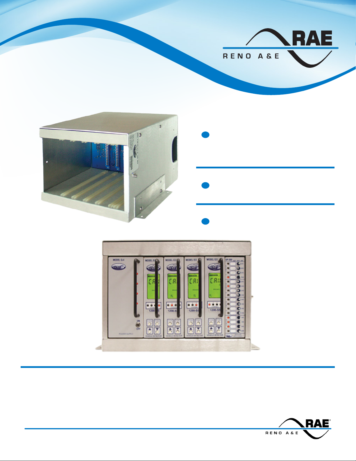
Reno A & E M-6D Detector Card Rack with a Q-4 Power Supply, four E/2-1200 Four Channel Detectors, and an SP-300 Detector Switch Panel
The M-6D detector card rack has been specially designed for NEMA TS 1 / TS 2 applications where shelf space
is at a premium. This high-density rack is capable of housing a power supply; four, single width (1.12 inch), four
channel detectors; and a half width BIU/2 bus interface unit or a Reno A&E Model SP-300 detector switch panel.
The Model SP-300 detector switch panel allows the user to disconnect or simulate detector call outputs.
3510 E. ATLANTA AVENUE, PHOENIX AZ 85040 +1.480.968.6407 EDITRAFFIC.COM
Page 2
M - 6D Specications
This is a Performance Specication. It is not intended to be used as Operating Instructions.
General Description: The Model M-6D detector card rack is designed to hold a Reno A&E Model Q4 power supply; up to four (4) Reno A&E Model E/2-1200 single width, four channel detectors; and a
Reno A&E Model BIU/2 half width bus interface unit or a Reno A&E Model SP-300 detector switch panel.
Reno A&E MH series wiring harnesses are available to simplify connections between the M-6D and other
components in the cabinet. The modular design of the M-6D detector card rack allows up to four (4) racks
to be joined together using one of several optional rear panels.
Card Rack Connectors (Power Supply and Detectors): PC board mounted 2 x 22 contact edge card
connectors with 0.156 inch (0.396 cm.) contact centers. Connector pin assignments are per NEMA TS1
/ TS2.
Card Rack Connector (Detector Switch Panel or Bus Interface Unit): PC board mounted 64-pin, female,
DIN 41612 type B series. The connector is oriented with Pin 1 located on top. Connector pin assignments
are per NEMA TS1 / TS2.
Back Plane Connector (Power Supply Input): 10 pin, dual row, female header, 0.165 inch (0.420 cm.)
pitch with gold plated contacts. (Molex p/n 39-31-0108 or equivalent). Mates with Molex p/n 39- 01-2105 or
equivalent. (See Pin Assignments - Power Supply Inputs table.)
Back Plane Connectors (Detector Inputs and Outputs): 10 pin / 8 pin, dual row, female header, 0.165
inch (0.420 cm.) pitch with gold plated contacts (Molex p/n 39-31-0108 / 39-31-0088 or equivalent). Mates
with Molex p/n 39-01-2105 / 39-01-2085 or equivalent. (See Pin Assignments - Detector Inputs and Outputs
tables.)
Back Plane Connector (Detector Switch Panel / Bus Interface Unit Outputs): 20 pin, dual row,
shrouded male header, 0.100 inch (0.254 cm.) pitch with gold plated contacts (Amp p/n 102618-8 or
equivalent). Mates with Amp p/n 1-87631-5 or equivalent. (See Pin Assignments - Detector Switch Panel /
Bus Interface Unit Outputs table.)
Ruggedized Construction: The M-6D housing is fabricated from 0.062 inch thick aluminum. The printed
circuit board is 0.062 inch thick FR4 material with 2 oz. copper on both sides and plated through holes.
Circuit board components are conformal coated with polyurethane.
Operating Temperature: -40º F to +180º F (-40º C to +82º C).
Weight: 2.80 lb (1.270 kg).
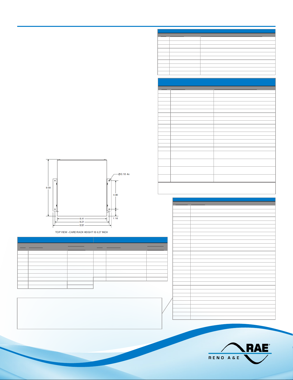
Size: 6.27 inches (15.93 cm) high x 8.41 inches (21.36 cm) wide x 9.58 inches (24.33 cm) deep (excluding
mounting anges). Mounting anges add 1.50 inches (3.81 cm.) to the width measurement.
Detector Inputs & Outputs (Channel 1 and 2) Detector Inputs & Outputs (Channel 3 and 4)
PIN Function
1 Phase Green Input - Ch 2 Pin 2 1 Phase Green Input - Ch 4 Pin 10
2 Loop Input - Ch 1 Pins 5 & E 2 Loop Input - Ch 3 Pins 14 & R
3 Loop Input - Ch 2 Pins 9 & K 3 Loop Input - Ch 4 Pins 18 & V
4 Call Output - Ch 2 Pin W 4 Call Output - Ch 4 Pin Y
5 DC Common Pin A 5 Phase Green Input - Ch 3 Pin 3
6 Phase Green Input - Ch 1 Pin 1 6 Loop Input - Ch 3 Pins 13 & P
7 Loop Input - Ch 1 Pins 4 & D 7 Loop Input - Ch 4 Pins 17 & U
8 Loop Input - Ch 2 Pins 8 & J 8 Call Output - Ch 3 Pin S
9 Call Output - Ch 1 Pin F
10 Output Emit. Commons Pins H, T, X, & Z
Edge Card
Connector Connector
PIN Function
Edge Card
Notes:
* BIU Address Bit 3 is connected to Logic Ground so that the default BIU address is 8.
Installing a jumper at J10 will add 1 to the address, installing a jumper at J9 will add 2 to
the address, and installing a jumper at J8 will add 4 to the address. Installing one or more
jumpers will assign an address value of 9 to 15 to the BIU address.
** Jumpers J39 through J49 allow isolation of the DC Common and/or Output Commons
on a per slot basis. Installing a BIU/2 or SP-300 in Slot 5 will tie the DC Common Bus to the
Output Commons Bus.
PIN Function Edge Card /DIN Connector Termination
1 Earth Ground Pin L - Slots 0-4, Pin A31 - Slot 5
2 Line Frequency Ref Pin B31 - Slot 5
3 DC + 3 Pin 17 & U - Slot 0
4 DC + 4 Pin 18 & V - Slot 0
5 DC Common Pin A - Slots 0-4, Pins A32 & B 32 - Slot 5
6 AC Neutral Pin M - Slot 0-4
7 AC Line Pin N - Slot 0-4
8 DC + 1 Pin 2 & B - Slot 0
9 DC + 2 Pin 3 & C - Slot 0
10 DC + Pin B - Slots 1-4, Pins A1 & B1 - Slot 5
Power Supply Inputs
Detector Switch Panel / Bus Interface Unit Outputs
PIN Function DIN Connector Termination
1 Detector 1 - Ch 1 Pin A4 - Slot 5
2 Detector 1 - Ch 2 Pin B4 - Slot 5
3 Detector 1 - Ch 3 Pin A5 - Slot 5
4 Detector 1 - Ch 4 Pin B5 - Slot 5
5 Detector 2 - Ch 1 Pin A6 - Slot 5
6 Detector 2 - Ch 2 Pin B6 - Slot 5
7 Detector 2 - Ch 3 Pin A7 - Slot 5
8 Detector 2 - Ch 4 Pin B7 - Slot 5
9 Detector 3 - Ch 1 Pin A8 - Slot 5
10 Detector 3 - Ch 2 Pin B8 - Slot 5
11 Detector 3 - Ch 3 Pin A9 - Slot 5
12 Detector 3 - Ch 4 Pin B25 - Slot 5
13 Detector 4 - Ch 1 Pin A26 - Slot 5
14 Detector 4 - Ch 2 Pin B26 - Slot 5
15 Detector 4 - Ch 3 Pin A27 - Slot 5
16 Detector 4 - Ch 4 Pin B27 - Slot 5
17 Logic Ground/DC Common Pins A, H, T, X, & Z - Slots 0 - 4
18 Logic Ground/DC Common Pins A, H, T, X, & Z - Slots 0 - 4
19 Logic Ground/DC Common Pins A, H, T, X, & Z - Slots 0 - 4
20 Logic Ground/DC Common Pins A, H, T, X, & Z - Slots 0 - 4
Note: Pin Assignments with BUI/2 installed in Slot 5 are Pin 12 - OPTO Input
(SP-300 Installed in Slot 5 - J38)
Pins A32 & B32 - Slot 5
Pins A32 & B32 - Slot 5
Pins A32 & B32 - Slot 5
Pins A32 & B32 - Slot 5
1, Pin 13 - OPTO Input 2, Pin 14 - OPTO Input 3, Pin - 15 - OPTO Input 4, and
Pin 16 - OPTO Input Common.
Jumper Function
J7 Power Supply Generated Line Frequency for BIU
J8* BIU Address Bit 2 *
J9* BIU Address Bit 1 *
J10* BIU Address Bit 0 *
J16 Serial Communications Address Bit 1 - Slot 0
J17 Serial Communications Address Bit 1 - Slot 4
J18 Serial Communications Address Bit 1 - Slot 2
J19 Serial Communications Address Bit 2 - Slot 0
J20 Serial Communications Address Bit 3 - Slot 0
J21 External Reset Bus - Slot 0
J23 Serial Communications Address Bit 0 - Slot 0
J24 External Reset Bus - Slot 4
J25 External Reset Bus - Slot 3
J31 External Reset Bus - Slot 2
J32 External Reset Bus - Slot 1
J33 Installed with Power Supply in Slot 0 (Pin 2 to Pin B)
J34 Installed with Power Supply in Slot 0 (Pin 3 to Pin C)
J35 Detector Rx Bus to BIU
J36 Detector Tx Bus to BIU
J39** Slot 0 Output Commons to Output Commons Bus **
J40** Slot 1 Output Commons to Output Commons Bus **
J41** Slot 2 Output Commons to Output Commons Bus **
J42** Slot 3 Output Commons to Output Commons Bus **
J43** Slot 0 DC Common to DC Common Bus **
J44** Slot 1 DC Common to DC Common Bus **
J45** Slot 2 DC Common to DC Common Bus **
J46** Slot 3 DC Common to DC Common Bus **
J47** Slot 4 DC Common to DC Common Bus **
J48** DC Common Bus to Output Commons Bus **
J49** Slot 4 Output Commons to Output Commons Bus **
Jumpers
M - 6D (551-1302-00) 03/23/2020
© COPYRIGHT 2020. Eberle Design, Inc. All Rights Reserved.
 Loading...