

Page 1
E-1000
Loop Detector
Firmware Version 4.02
Operations Manual
Four Channe l Menu Driven Programmable Inductive Loop Vehicle
Detector Designed for Railroad Applications
Four Loop Inputs, Eight Vital Outputs, and Four Vital Inputs
Built-in Loop Analyzer for Each Channel
This manual contains technical in formation for the
E-1000 Loop Detector
pn 889-0503-01 Revision: April 2020
Page 2

Page 3

THE FOLLOWING PRODUCT WAS DESIGNED, INSPECTED, TES TED AND
MANUFACTURED IN THE USA BY EBERLE DESIGN, INC. IN PHOENIX, ARIZONA.
INFORMATION CONTAINED HEREIN IS PROPR IETARY TECHNICAL INFORMATION OF
EBERLE DESIGN, INC. PUBLICATION, REPRODUCTION OR USE IN WHOLE OR PART IS
NOT PERMITTED EXCEPT UNDER TERMS AGREED UPON IN WRITING. ALL
REGISTERED TRADEMARKS OF EBERLE DESIGN INC. ARE UNDER
MAINTENANCE NOTE
IT IS AN EBERLE DESIGN, INC. RECOMMENDATION THAT EACH UNIT BE TESTED
AT LEAST ANNUALLY TO ENSURE COMPLIANCE WITH FACTORY
SPECIFICATIONS AND MEETS PROPER OPERATIONAL STANDARDS. THE
RESULTS OF THIS TESTING WILL BE DOCUMEN T ED .
© COPYRIGHT
Page 4

Page 5

Model E-1000 Operations Manual
Table of Contents
Section 1 General Description ......................................................................................... 1
Section 2 General Characteristics ................................................................................... 2
2.1 Loop Frequency ..................................................................................................... 2
2.2 Sensitivity ............................................................................................................... 2
2.3 Presence / Pulse .................................................................................................... 2
2.4 Call Delay ............................................................................................................... 2
2.5 Call Extention ......................................................................................................... 2
2.6 Max Presence Timer .............................................................................................. 2
2.7 End-Of-Green (EOG) ............................................................................................. 2
2.8 Option 1: Loop Inductance Display ......................................................................... 3
2.9 Option 2: Loop Inductance -∆L/L Display ................................................................ 3
2.10 Option 3: Call Extention Control ........................................................................... 3
2.11 Option 4: Noise Filter Disable ............................................................................... 3
2.12 Option 5: Phase Green Loop Compensation ........................................................ 3
2.13 Option 9: Third Car Passage ................................................................................ 3
2.14 Option 10: Directional Logic.................................................................................. 4
2.15 Option 11: Audible Detect Signal .......................................................................... 5
2.16 Option 12: Detector Disconnect ............................................................................ 5
Section 3 Specifications .................................................................................................. 7
3.1 Physical.................................................................................................................. 7
3.2 Minimum Flash Dip Switch Programming ............................................................... 7
3.3 Operational ............................................................................................................ 7
3.4 Tables: Sensitivity, -∆L/L, & Response Time ............ Error! Bookmark not defined.
3.5 Table: Default Settings ........................................................................................... 8
3.6 Tables: Pin Assignments ........................................................................................ 9
Section 4 User Interface ..................................................................................................11
Section 5 Installation and Set-Up ...................................................................................12
5.1 Program Mode Display Screens ............................................................................12
5.2 Normal Mode Display Screens ..............................................................................15
5.3 Loop Fail Indications .............................................................................................18
5.4 Setting Sensitivity using the Bar Graph .................................................................18
5.5 Setting Sensitivity for Motorcycle Detection using the Bar Graph ...........................19
5.6 Full Restore to Factory Default Settings ................................................................19
5.7 Display Test ..........................................................................................................19
Section 6 Block Diagram .................................................................................................20
Section 7 Theory of Operation ........................................................................................21
Section 8 Maintenance and Troubleshooting ................................................................22
8.1 Troubleshooting Power Problems ..........................................................................22
8.2 Troubleshooting Initialization Problems .................................................................22
8.3 Troubleshooting Loop Fail Problems .....................................................................23
8.4 Troubleshooting Intermittent Loop Fail Problems ...................................................24
8.5 Troubleshooting Intermittent Detector Lock-Ups ....................................................24
8.6 Troubleshooting Delay Problems ...........................................................................24
8.7 Things to Know About Loops .................................................................................25
Page 6

Page 7

Section 1 General Description
This product manual was written for people installing, operating, and maintaining the Reno A & E Model E-1000
Series inductive loop vehicle detector. The Model E-1000 is a four channel, rack mount type, inductive loop
vehicle detector designed to meet or exceed NEMA Standards TS 2-1992 and is downward compatible to N EMA
Standards TS 1-1989.
The Model E-1000 uses a microcontroller to monitor and process signals from the loop / lead-in circuits, Phase
Green Inputs, and the reset input. It uses these inputs to deter mine how to control the four detector channel outputs
and the four TS 2-1992 stat us outputs (if equipped). A Liquid Crystal Display ( LCD), four light emitting diodes
(LEDs), and four front panel pushbuttons are used to display and program all detector functions. Several
diagnostic modes are available to aid technicians and service personnel in troub leshoot ing detect io n problems.
The use of an LCD is what distinguishes this detector from that of other manufacturers. It allows more
information, never before available, to be displayed to the user during nor mal operation of the detector. The LCD
makes it easy to view and adjust all programmable detector options and settings. It is no longer necessary to check
or change detector sett ings with DIP switches. An eight-se gment bar graph at t he top of the LCD ca n be used to
provide a graphical representation of the relative change of inductance as seen by the detector at the current
sensitivity level. The bar graph automatically takes into account loop size, loop inductance, number of loops,
number of turns, loop geometry, lead-in length, etc. The bar graph functions as a sliding scale that relates to the
programmed Sensitivity Level. The first (left-most ) bar graph segment represents the mini mum inductance change
necessary for the detector to output a call at the currently selected sensitivity level. Larger inductance changes will
indicate more se gments. Each additional segment indicates that the next sensitivity level has also been met or
exceeded. When used in this manner, t he bar graph provides an indication of w hethe r the s ens itivit y is set too high
or too low, facilitating the ideal setting of the sensit ivity level.
All programmed settings are stored in non-volatile memory and can only be changed by programming new
settings. Loss of power or a de tector reset will not change any of t he programmed settings. If a loop failure
occurs, the LCD will display the type of loop failure as L lo (for -25% change or shorted loop conditions) or L hi
(for +25% change or open loop c onditions). Each loop failure is counte d and accumulated in the Loop Failure
Memory. The number of failures since the last detector reset or power interrupt ion is very us eful infor mation
during analysis of intermittent loop operation.
The Model E-1000 Series detector is a scanning detector. The scanning operation sequentially activates the ON
and OFF cycle of each channel’s oscillator. Since only one channel’s loop(s) is (are) active at a given time,
crosstalk between adjacent loops connected to t he same scanning detector is minimized. The Model E-1000
Series’ unique scanning process also disconnects the capacitors and dampens the oscillator during the o ff cycle.
This eliminates oscillation past the OFF point (ringing or deca y) every time the loop circuit is scanned which can
result in crosstalk. When operating in the Program Mode, the Model E-1000 Series d isplays the real time loop
freque ncy rea ding for each channel. The eight frequency settings ca n be incremented or decremented to p rovide
precise frequency readings, removing any guesswork when cha nging frequency settings to eliminate crossta lk.
NOTE: Adjacent loops connected to different c hannels of a non-scanning detector or different scanning detectors
should be set to different frequencies with maximum separation.
The Reno A & E Model E-1000 Series utilizes the first major innovation in inductive loop detectors since the
introduction of digital detectors. The programming of all of the detector’s parameters with four normally open
pushbutton switches not o nly simplifies setup by removing binary coded DIP s witches, but also increases the
reliability of the detector by eliminating the dependence on switch contacts during normal operation. The detailed
descriptions displayed on the LCD eliminate the interpretation of numerous LED flash rates to determine the
detector status. In addition, the Model E-1000 offers t he versatility of software c ontrol. Special functions are
possible with a simple change of the socket-mounted microprocessor. Special functions are de fined as unique
options (e.g. Option 5, Opt ion 12, etc.). Spe cial option functio ns are activated thro ugh the use o f the LCD menu
option programming.
The Model E-1000 Series is comprised of the following detectors:
E-1100-SS For 332 cabinet (170 controller) applications ca lling for a four channel, 2” wide (double width),
E-1200-SS For NEMA TS 1 -1989 and TS 2-1992 applications calling for a four channel, four c hannel, 2”
E/2-1200-SS For NEMA TS 1-1989 and TS 2-1992 applicat ions calling for a four channel, 1.2” wide (single
E/2-1300-SS For special applications calling for a four channel, 1.2” w ide (single width), rack mount detector
rack mount detector with solid state outputs and an audible detect signal (buzzer).
wide (double width), rack mount detecto r with solid state outputs and an audible detect signal
(buzzer).
width), rack mount detector with solid state outputs and an audible detect signal (buzzer).
with solid state outputs and an audible detect signal (buzzer).
889-0503-1 Model E-1000 Operations Manual Rev Apr 2020 Page 1 of 25
Page 8

Section 2 General Characteristics
2.1 LOOP FREQUENCY
There are eight (8) selectable loop frequency settings (nor mally in the range o f 20 to 100 kilohertz) pe r channel.
The actual loop operating frequency is a function of the loop / lead-in network and the components of the loop
oscillator circuit. The d igital display of the actual loop operating frequency for each setting makes it easy to
quickly identify and eliminate crossta lk in the most difficult to configure intersections. The frequency display is
typica lly very stab le when the loop is vacant and veh icles are not passing nearby the loops. If the reading is
varyin g by more than ±1 in the last digit, this is an indication of possible crossta lk betwee n loops.
2.2 SENSITIVITY
There are eight (8) selectable loop frequency settings (normally in the range of 20 to 100 kilohertz) per channel.
The actual loop operating frequency is a function of the loop / lead-in network and the components of the loop
oscillator circuit. The digital display of t he actual loop operating frequency for each setting makes it easy to
quickly identify and eliminate crossta lk in the most difficult to configure intersections. The frequency display is
typica lly very st able when t he loop is va cant and ve hicles ar e not passi ng nearby the loops. I f the readin g is
varyin g by more than ±1 in the last digit, this is an indication of possible crosstalk between loops.
2.3 PRESENCE / PULSE
One of two mutually exclusive modes of operation for each channel is available. Presence or Pulse mode is
toggled by momentarily pressing e ither the (UP) or (DOWN) butto n.
PRESENCE MODE: Provides a call hold time of at least four minutes (regardless of vehicle size) and typically one to
three hours for an automobile or truck.
PULSE MODE: An output Pulse of 125 ±10 milliseconds duration is generated for eac h ve hicle ente ring t he loo p
detection zone. Each detected vehicle is instantly tuned out if it remains in the loop detection zone longer than two
seconds. This enables detection of subsequent vehicles entering the loop detection zone. After each vehicle leaves
the loop detection zone, the channel resumes full sensitivity within 0.5 seconds.
2.4 CALL DELAY
Each channel’s Call Delay is ad justab le from 0 t o 255 seconds in one-second steps. Call Delay time starts counting
down w he n a veh ic le e nt ers t he loo p detect ion zone. The re maining Call Dela y time is c ontinuously displa yed on
the LCD. Whenever a Phase Green Input (call delay override) signal (pin 1, 2, 3, or 10) is active (low state), the
Call Delay function fo r that channel is aborted and the C all Delay time forced to zero.
2.5 CALL EXTENTION
Each channel’s Call Extension is adjustable from 0 to 25.5 sec onds in 0.1-second steps. Extension time starts
counting down when the last vehicle clears the loop detection zone. The remaining Call Extension time is
contin uous ly d isp la yed o n the LCD. Any veh icle ente r ing t he lo op de tec tio n zo ne d uri ng the Ca ll Ext ens io n ti me
period causes the channel to return to the Detect state, and later, when the last vehicle clears the loop detection
zone, the full Call Exte nsion time starts counting down again. (See Option 3, Call E xtension Control, for an
alternate mode of operation for Call Extension.)
2.6 MAX PRESENCE TIMER
When activated, each channel’s Max Presence timer is adjustable from 1 to 999 seconds in one-second steps. A
setting of OFF turns the Max Presence timer off. The Max Presence function is used to limit presence time, by
automatically resetting the channel. If this function is enabled (ON), the Max Pre sence timer begins counting
down when a call is initiated and t he remaining ti me is continuously displaye d on the LCD. I f the loop becomes
vacant before the Max Presence timer reaches zero, the call is dropped and no automatic reset occurs. If the EndOf-Green (EOG) function is not enabled (OFF) and the call is still present when the Max Presence timer reaches
zero, the cha nnel then is aut omatically reset. If the EOG functi on is e nabled (ON) and the call is still present w hen
the Max Presence timer reaches zero, the channel enters a Wait state. The Wait state continues until either the loop
becomes vacant or the Phase Gree n Input signal for a channel (p in 1, 2, 3, or 10) transitions fro m green to not
green with the call still present. If the loop becomes vacant first, the call is dropped and no automatic reset occurs.
If the P hase Gree n Input tr ansitio ns from gre en to not green whil e a channe l is in a W ait state , the chan nel is
automatically reset. The signals on pins 1, 2, 3, and 10 are also called Call Delay Overrides. (See Section 3.2,
Phase Green Input specifica t ion for volt age leve ls . )
2.7 END-OF-GREEN (EOG)
Each channel’s EOG setting can be toggled O N or OFF b y moment arily pr essing either the (UP) or (DOWN)
button. The EOG function is used to synchronize resetting of a detector with the termination of the associated
phase green. The assumption is that t his is the sa fest point in t ime to reset the c hannel. T his assumption is based
on the premise that at the termination of the associated phase green, traffic should be moving, and therefore, a reset
would not result in the loss of a call when traffic comes to rest over the loop(s). The EOG func tion is only
889-0503-1 Model E-1000 Operations Manual Rev Apr 2020 Page 2 of 25
Page 9

available when the Max Presence function is set between 1 and 999 seconds. It is not available when the Max
Prese nce fun ct io n is O FF. W he n t he E OG function is enabled (ON), the channel will automatically be reset at the
same time the Phase Green Input signal (pin 1, 2, 3, or 10) transitions from the ON state to the OFF state, if the
Max Presence Time has counted down to zero and is resting in the wait state . T he s igna ls on p ins 1 a nd ar e a lso
called Call Delay Overrides. (See Section 3.2, Phase Green Input specifications for voltage levels.)
2.8 OPTION 1: LOOP INDUCTANCE DISPL AY
Each cha n ne l’s Loo p I nd uct a nce Dis p la y se tt in g ca n be t o ggle d O N or O FF b y mo me nta r il y pre ss i ng e it her the
(UP) or (DO W N ) b u t to n. W hen this o p ti o n is e nabled (ON ) , t he LC D d is p la ys the tota l lo o p inductanc e (a c t ua l
loop inductance plus actual lead-in in ducta nce) in m icrohe nries for loop induct ance va lues i n the ran ge of 20 to
2500 microhenries. By recording the inductance of the loop / lead-in circuit when it is first insta lled, the actual
inductance can be compared to the expected inductance to help identify defective loop / lead-in circuits. Loop /
lead-in inductance can be easily estimated using the simple formulas included in Section 8.7 of this manual.
NOTE: Enabling this option act ivates it for all c hannels. This option is a utomatically disabled 15 minutes after
activation or on loss of power.
2.9 OPTION 2: LOOP INDUCTANCE -∆L/L DISPLAY
Each cha n ne l’s Loo p I nd uct a nce -∆L/L Display sett ing can be toggled ON or OFF by momentarily press ing either
the (UP) or (DOWN) but ton. When th is option is e nabled (ON), the LCD displays the percentage of
induct ance change (-∆L/L value) during the Call state. To fac ilitate the viewing of the maximum amount of
change in the -∆L/ L value w hile tra ffic is i n motion o ver the de tectio n zone, t he channe l holds t he peak -∆L/L
value for a period of two seconds. NOT E: Enabling this option activates it for all channels. This option is
automatically disabled 15 minutes after activation or on loss of power.
2.10 OPTION 3: CALL EXTENTION CONTROL
Each cha nnel’ s Cal l Exte nsion C ontro l set ting ca n be to ggled O N or OF F by mo mentar ily pre ssin g eithe r the
(UP) or (DO WN ) b ut to n. W he n t h is o pt io n is e nab led (O N) , t he c ha n nel w ill e x tend ca l ls f or t he pr o gra mme d
extension t i me only when the Phase Gree n Input s ignal (p in 1, 2, 3, or 10) is active. When this option is OFF, the
channel extends ALL calls for the programmed exte nsion time. The signals o n pins 1, 2, 3, and 10 are also ca lled
Call Delay Overrides. (See Section 3.2, Phase Green Input specifications for voltage levels.)
2.11 OPTION 4: NOISE FILTER DISABLE
The detector’s Noise Filter Disable setting can be toggled ON or OFF by momentarily pressing either the (UP)
or ( DO WN ) b utt o n. W he n Op t io n 4 is e nab le d ( ON ), inte r na l no is e f ilt er in g is d isa ble d t hus p ro vid in g a fas te r
response time. When this opt ion is OFF, internal noise filtering is utilized. When the detector is used in speed
and/or occupancy applications, the noise filter s hould be disabled (i.e. Option 4 ON) to provide the most accurate
data possible. It is recommended that this option not be activated. The factory default setting o f OFF provides
stable operation in high crosstalk environments. NOTE: Enabling this option activates it for all channels.
Changing the setting of this feature will reset all detector channels.
The Loop Fail Count is not reset when the setting of Option 4 is changed. Also, changing the setting of Option 4
will not cause the prior Loop Fail indication to cease (see Section 5.3, Loop Fail Indications).
2.12 OPTION 5: PHASE GREEN LOOP COMPENSATION
Each channel’s Phase Green Loop Co mpensation setting can be toggled ON or OFF by mo mentarily pressing
either the (UP) o r (DOWN) button. When Option 5 is enabled (ON), normal loop compensation is used until
the Phas e G re e n I n p ut signal (p i n 1 o r 2) becomes active. Once the Phase Green Input signal is active, the channel
desensitizes the loop. Maximum desensitization is 0.05% (-∆L/L). This desensitization tunes out small changes,
such as adjacent lane pickup, therefore minimizing the chance of max timing an empt y lane. Note: A small
motorcycle may also be tuned out in a short period o f time following the start of Phase Green. This optio n is
useful in minimizing false detection resulting from adjacent lane pickup when a channel must be run with a high
sensitivity s etting. When Opt ion 5 is not enabled (OFF) , norma l loop compensation is used.
2.13 OPTION 9: THIRD CAR PASSAGE
Each channel’s Third Car Passage setting can be toggled ON or OFF by momentarily pressing either the (UP) or
(DO WN ) b ut to n. Op tion 9 is a paired channe l option. This means that it takes two c hannels to imple ment the
feature. Therefore, when this option is toggled ON or OFF in one channel, its paired channe l is a lso set to the sa me
state. In the Model E-1000, C hannel 1 is paired with C hannel 2 and Channe l 3 is paired with C hannel 4. NO TE:
Option 9 is mutually exclusive with Opt ion 10. Turning ON one option will automatically tur n OFF the other
option.
When Op t ion 9 is e nab led (ON ) , t he o ut pu t o f the tw o p air ed c ha n ne ls a re logically ANDed together. This means
that while the loops for both of the paired channels are occ upied, a call will be output on both channe ls. While
only one channel is occupied, or neither channel is occupied, a call will not be output for either cha nne l. The f irs t
889-0503-1 Model E-1000 Operations Manual Rev Apr 2020 Page 3 of 25
Page 10
Loop B
Loop A
channel with detection will enter a pend ing state w hile wait ing for detect ion on the ot her pa ired cha nnel. While in
the pending state, the LCD will show Pnd on the d isplay.
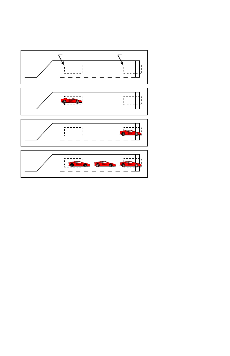
This feature is intended to be used in Protected / Permissive left turn situations. The expected ins ta llation is a stop
bar loop for the left turn lane connected to one c hanne l, a queue detect ion loop (with a s mall amount o f delay ti me
programmed) for the left turn lane connected to the other channel, and the output of either channel connected to the
Vehicle Call input for the protected movement of the traffic controller.
Basic Installation - Loop A is the
Queue Detection loop and Loop
B is the Stop Bar loop.
Car enters Loop A - No call is
output.
Car proceeds to Loop B - No call
is output.
Additional cars enter the left turn
lane - When the back of the
queue reaches Loop A while a
car is still over Loop B, a call
will be output.
When Third Car Passage is turned on, as the first vehicle enters the left turn lane it will dr ive over t he queue
detection loop. Since there is no vehic le over the stop bar loop, there is no call output genera ted. The vehicle
advanc es to t he sto p bar loop. Still, no out put is gene rated beca use the re is no veh icle o ver the queue detection
loop. If the vehicle traffic in the left turn lane backs up to the queue detection loop, then the stop bar loop and the
queue detection loop will both be occupied at the same time. This will cause the detector to generate a call to the
traffic co ntroller to service the protected movement for the left turn. This should help clear the queue of vehicles
in the left turn lane. The spacing between the stop bar loop and the queue detection loop controls the size of the
queue needed to generate a call to the protected movement of the controller. The delay time on the Queue
Detection loop should be sufficiently long that vehic les driving over this loop to enter the queue do not generate a
call.
2.14 OPTION 10: DIRECTIONAL LOGIC
Each c ha n nel’s D ire c t ional Lo gic setting can be toggled ON or OFF b y momentarily press ing either the (UP) or
(DOWN) button. Option 10 is a paired c hannel option. This means that it takes two channe ls to implement t he
feature. Therefore, when this option is toggled ON or OFF in one channel, its paired channe l is a lso set to the sa me
state. In the Model E-1000, C hannel 1 is paired with C hannel 2 and Channe l 3 is paired with C hannel 4. NO TE:
Option 10 is mutually exclusive with Opt ion 9. Turning ON one option will automatically tur n OFF the other
option.
When Op tion 10 is enab led (ON ), dire ctiona l logic is enabled. Directional logic starts with a detection on one
channel. This channel will go into the pending state, display Pnd on the LC D , a nd N O T output a c a l l. W hen both
of the paired channe ls have detect ion, the last channel to have d etect ion will output a call until the detection for the
last c ha n ne l e nd s , e ve n if t h e d e te c t ion ends fo r t he fi rs t c hannel. None of t he t i mi n g f un c t io ns of the f ir s t channe l
with a detection will ti me (Delay, Extens ion, Max Presence, a nd Detector Disconnect) a nd the first channel w ill
always operate in the Presence Mode regardless of the programming of the channel.
This feature is intended to be used in parking lot applications where vehicles can enter or exit from the same lane,
freeway ramps for wrong way detection, and left tur n la ne s w he re o t her movements in t he inte rs ec ti o n te nd t o cl ip
the detection zone of the left turn lane. The expected installation is two loops, one after the other in the same lane,
spaced anywhere from slightly overlapping to 6 feet apart. NOTE: Contact a Field Engineer at Reno A & E
regarding proper loop configurations and spacing for specific applic ati ons.
889-0503-1 Model E-1000 Operations Manual Rev Apr 2020 Page 4 of 25
Page 11

Loop B
Loop A
When Directional Detectio n is turned on, a vehicle entering the first loop will cause that channel to enter t he
pending state. As the vehicle enters the second loop w hile still occupying the first loop, the second channel will
enter the Call state while the firs t channe l remains in t he pending s tate. A call is never outp ut on the first c hannel
with a detection. Under normal conditions both outputs can never be on at the same time. However, if one of the
loops fail, both outputs will come on and stay on until the failure is correc te d.
Basic Instal lation
Car enters Loop A - No call is output Car enters Loop B - No ca ll is output
Car proceeds to Loop B Car proceeds to Loop A
Call is output o n Channel B Call is ou tput on Channel A
2.15 OPTION 11: AUDIBLE DETECT SIGNAL
Each c hanne l’s, A udible Detec t Sig nal set ting c an be t oggled ON or OFF b y mome ntar ily pre ssing e ither the
(UP) or (DOWN) butto n. Only one channel can be turned ON at a time. Turning this option ON for one
channel auto matically turns it OFF for the other channels. W hen this o ption is enable d (ON), a n audible signal will
be activated whenever the detection zone for the selected channel is occupied. The audible signal indicates actual
occupancy of the loop detection zone. Timing and disconnect functions have no effect on the audible signal. This
feature allows a technician to watch the detection zone on the street and confirm correct detector operation without
having to look at the detector display as well. NOT E: This option is automatically disabled 15 minutes after
activation or on loss of power.
2.16 OPTION 12: DETECTOR DISCONNECT
Each channel’s Detector Disconnect se tting can be toggled ON o r OFF and the Extension t imer toggled between
ON and OFF by momenta r il y pr es sing ei t h er t he (UP) or (DOWN) button. The Detector Disconnect feature
require s tha t the Phase Gree n Inp ut for t he channel be connected to the proper controller phase. When the Phase
Green I nput is no t a c t i ve , t he c hannel s hall ope ra te no r mally. W hen the P ha s e Gr e e n I np ut is a c t iv e , t he e xt e nsion
timer will start to count down at the end of each detection. If this timer reaches zero before the next detection, this
channel will no longer output a call until the Phase Green Input is not active. Since the extension timer is used as a
disconnect timer while in this mode, two different disconnect types are available:
Optio n 12.1 OF F : Extension timi ng still occurs and the extension timer is also t he disconnect timer during phase
green. This will cause the call output to re main in the Call state until disconnect oc curs. This may allow the
user to use gap times appropriate for the advance loops without considering the effects on the stop bar loops.
Option 12.1 ON: E xte ns ion timing is disabled and the extension timer is used as the disconnect timer. T his will
cause the call output to follow the occupation of the loop detection zone until disconnect occurs.
This feature is intended to be used in applications where a loop at the stop ba r is not needed after any waiting
queue in the associated traffic lane is moving during the green phase. The expected installation is a stop bar loop
(typically a 20΄ to 30΄ long detection zone) and an advance detection loop (typically a 6΄ long detection zone) for a
single traffic lane. This feature provides a means for keeping the stop bar loop from placing ca lls to the traffic
controller after the stop bar loop has served its intended purpose during the beginning period of the associated
green phase. The channel connected to the stop bar loop would have the Detector Disconnect feature turned ON
and have a programmed extens ion time tha t functions as the disconnect time. The channel connected to the
advance detection loop would be programmed as normal.
889-0503-1 Model E-1000 Operations Manual Rev Apr 2020 Page 5 of 25
Page 12

Detection Zone
Phase Green
Output w/ 12.1 Off
Output w/ 12.1 On
This example assumes an extension time of 2 seconds. The dott ed lines show where di sconnect would occur. Phase
Green is the state of the light (actual Phase Green Input is inv er ted).
When the Detector Disconnect feature is turned ON and the signal is not green, the channel outputs calls to the
traffic controller as usual. W hen the signa l turns gree n, vehicles begin to move and eventually the stop ba r
detection zone is cleared. At the time that the stop bar detection zone is cleared the disconnect timer begins to
count down. If another vehicle enters the stop bar detection zone before the disconnect timer reaches zero, the
channe l o utp u ts the ne w c al l t o the traffic controller and the disconnect timer is reset to its initial value. Once the
stop bar detection zone remains clear for a time equal to the programmed disconnect time, the detector channel is
disable d a nd w il l no t ge nera te a ny fu rt her c alls t o t he traffic controller until after the green has terminated. When
the stop bar detection loop is disabled, the green phase can only be extended by vehicles detected by the advance
detection loop. NOTE: The disco nnect t imer will alwa ys time a n initial gap each t ime tha t the p has e t ur ns gre e n.
If Option 12.1 is OFF, the channel will generate an output for the specified extension time at the start of each green
phase.
889-0503-1 Model E-1000 Operations Manual Rev Apr 2020 Page 6 of 25
Page 13

Normal operation
Continuous Low or On State
Detector failure
Continuous High or Off State
Open loop
50 millisecond On time, 50 millisecond Off time
Shorted loop
50 millisecond On time, 100 millisecond Off time
Excessive ind uctance change ( ±25%)
50 millisecond On time, 150 millisecond Off time
Section 3 Specifications
3.1 PHYSICAL
EIGHT: 6 oz. (170 gm).
W
S
IZE: Mode l E (do u ble w idt h face p lat e ) - 4.50 inches (11.43 cm) high x 2.00 inches (5.08 cm) wide x 6.88 inches
(17.46 cm) long including connector (not including front handle). Model E/2 (single width faceplate) - 4.50 inches
(11.43 cm) high x 1.20 inches (2.84 cm) wide x 6.88 inches (17.46 cm) long including connector (not including
front handle). Handle adds 1.00 inch (2.54 cm) to depth measurement.
O
PERATING TEMPERATURE: -40° F to +180° F (-40° C to +82° C).
C
IRCUIT BOARD: Printed circuit boards are 0.062 inch thick FR4 material with 2 oz. copper on both sides and
plated through holes. Circuit board and components are conformal coated with polyur ethane.
C
ONNECTOR: 2 x 22 pin edge card connector with 0.156-inch (0.396 cm.) contact centers. Key slots located
between pins B / 2 & C / 3, E / 5 & F / 6, and M / 11 & N / 12.
3.2 MINIMUM FLASH DIP SWITCH PROGRAMMING
OWER: 10.8 to 30 VDC, 120 mA maximum, 1.8 Watts maximum.
P
L
OOP INDUCTANCE RANGE: 20 to 2500 micro henries w ith a Q factor of 5 or greater.
L
OOP INPUTS: Transformer isolated. The minimu m capacita nce added is 0.068 microfarad.
L
IGHTNING PROTECTION: Meets and/or exceeds all applicable NEMA TS 1-1989 specifications for transient
voltage protection. Each channel can tolerate, without damage, a 10 microfarad capacitor charged to 2,000 volts
being discharged directly into the loop input terminals, or a 10 microfarad capacitor charged to 2,000 volts bein g
discharged between either loop terminal and earth ground.
R
ESET: Meets and/or exceeds NEMA TS 1-1989 and TS 2-1992 detector specifications. Applicat ion of a 30-
millisecond low state (0 to 8 VDC) t o pin C resets all cha nnels. The detector can a lso be reset by removing and
reapplying power or by changing t he setting of Option 4 (Noise Filter Disable). E ach detector channel can be
independently reset by pressing the CHAN button until the desired c hannel is selected, then pressing and ho lding
the CHA N b ut t o n fo r t hr e e se c o nd s . A ls o, c ha n gi n g either the sensitivit y or loop fr e q uency o f a channe l will res e t
that channel.
P
HASE GREEN INPUTS: Also known as Call Delay Overrides. Meets and/or exceeds all NEMA TS 1-1989 and TS
2-1992 requirements. Application of a low state voltage (0 to 8 VDC) to pin 1 (Ch. 1) and/or pin 2 (Ch. 2) and/or
pin 3 (Ch. 3) and/or pin 10 (C h. 4) causes the delay timer for the channel to abort t he delay timing function a nd
also provides control for Phase Green Loop Compensation, Max Presence Timing (End-of-Green), Extensio n
timing, and Detector Disconnect, if the features are programmed.
F
AIL-SAFE OUTPUTS: Per NEM A TS 2-1992 - co nducting state indicates detection output. Each detector channel
output defaults to a CALL state for any loop failure condition or loss of power.
C
HANNEL STATUS OUTPUTS: Per NEM A TS 2-1992 - each channel has an output to communicate the status states
of the c hannel as follow s:
SOLID STATE OUTPUT RATING: Optically isolated. 30 VDC maximum collector (drain) to emitte r (source). 100
mA ma ximum s atu rat ion c urre nt. 2 VDC maxi mum t rans isto r satur atio n vol tage. The o utput is pr otect ed w ith a
33-volt Zener diode connected between the collector (drain) and emitter (source).
3.3 OPERATIONAL
ISPLAY: The LCD backlighting illuminates whenever any pushbutton is pressed. The backlighting will
D
extinguish 15 minutes after the last pushbutton press.
889-0503-1 Model E-1000 Operations Manual Rev Apr 2020 Page 7 of 25
Page 14

Respons e Time
(Option 4 O FF)
Respons e Time
(Option 4 ON)
OFF
-------
-------
-------
1
0.64%
160 ±50 ms
35 ±7 ms
2
0.32%
160 ±50 ms
35 ±7 ms
3
0.16%
160 ±50 ms
35 ±7 ms
4
0.08%
160 ±50 ms
35 ±7 ms
5
0.04%
160 ±50 ms
35 ±7 ms
6
0.02%
160 ±50 ms
48 ±10 ms
7
0.01%
160 ±50 ms
79 ±17 ms
8
0.005%
160 ±50 ms
138 ±28 ms
9
0.0025%
160 ±50 ms
261 ±51 ms
CALL
-------
-------
-------
Respons e Time
(Option 4 O FF)
Respons e Time
(Option 4 ON)
OFF
-------
-------
-------
1
0.64%
160 ±50 ms
35 ±7 ms
2
0.32%
160 ±50 ms
35 ±7 ms
3
0.16%
160 ±50 ms
35 ±7 ms
4
0.08%
160 ±50 ms
35 ±7 ms
5
0.04%
160 ±50 ms
35 ±7 ms
6
0.02%
160 ±50 ms
48 ±10 ms
CALL
-------
-------
-------
four, then add these times together.
D
ETECT INDICATOR: Each channel has a super bright, high intensity, red light e mitting diode (LE D) to indicate a
Call Output, Delay Timing, Extension Timing, Pending State, or Failed Loop co nditio n.
R
ESPONSE TIME: Meets or exceeds NEMA TS 1-1989 and TS 2-1992 response time specifications. (See Section
3.4 for actual response times.)
S
ELF-TUNING: The detector automatically tunes and is operational within two seconds after application of power
or after being reset. Full sensitivity and hold time require 30 seconds of operation.
E
NVIRONMENTAL & TRACKING: The detector is fully self-compensating for environmental changes a nd loop drift
over t he full te mperature range and the entire loop inductance r ange.
G
ROUNDED LOOP OPERATION: The loop is olation transformer allows operation with poor qualit y loops (which may
include one short to ground at a single point).
L
OOP FEEDER LENGTH: Up to 5000 feet (1500 m) maximum with proper feeder cable and appropriate loops.
LOOP (FAIL) MONITOR: If the tot a l in duc ta nc e o f t he c ha n ne l’s loo p inp ut ne tw or k go e s o ut o f t he ra nge sp ec i fied
for the detector, or rapidly changes by more than ±25 %, the channel will immediate ly e nte r t he Fail-Safe mode and
display LOOP FAIL o n the LCD. The type of loop failure will also be disp layed as L lo (for -25% change or
shorted loop conditions) or L hi (for +25% change or open loop conditions). This will continue as long as the loop
fault exists. However, if the detector is reset, or power is momentarily lost, the detector will retune if the
loop inductance is within the acceptable range. If any type of loop failure occurs in one (or more) loop(s) in
a group of two or more loops wired in parallel, the detector will not respond with a Fail-Safe output
following any type of reset. It is essential that multiple loops wired to a common detector channel always be
wired in series to ensure Fail-Safe operation under all circumstances. At the time of a loop failure, the
channel’s LED will begin to flash at a rate of three flashes per second. The LED will continue this display pattern
until the channel is manually reset or power is removed. If the loop self-he als, the LOO P FAIL message on t he
LCD will extinguish and the channel will re sume operation in a normal manner; exce pt the LED will continue t he
three flashes per second display pattern, thus pro viding an alert that a prior Loop Fail condition has occurred. Each
loop failure for the channel is counted and accumulated into the Loop Fail Memory. The total nu mber of loop
failures written into the Loop Fail Memory (since the last power interruption or manual reset) is viewed by
stepping through the channel’s functions in Program Mode until the LO O P FAIL messa ge is dis played .
3.4 TABLES: SENSITIVITY, -∆L/L, & RESPONSE TIM ES
MODELS E-1100, E-1200, and E/2-1200
Sensitivity -ΔL/L
MODEL E/2-1300
Sensitivity -ΔL/L
NOTE: Entries in these two t ables are based on the assumption that all channe ls are set to the same sensitivity. To approximate
response time for a detector with the channels set to different sensitivities, look up the response time for each channe l and divide it by
889-0503-1 Model E-1000 Operations Manual Rev Apr 2020 Page 8 of 25
Noise Filter Enabled
Noise Filter Enabled
Noise Filter Disabled
Noise Filter Disabled
Page 15

Pin
Function
Pin
Function
A
DC Common
1 Channel 1 Phase Green Input
B
DC + 2
Channel 2 Phase Green Input
C
Reset Input
3 Channel 3 Phase Green Input
D
Channel 1 Loop Input
4 Channel 1 Loop Input
E
Channel 1 Loop Input
5 Channel 1 Loop Input
F
Channel 1 Output, Collector (Drain)
6 No Connection
H
Channel 1 Output, Emitter (Source)
7 Channel 1 TS 2 Status Output
K
Channel 2 Loop Input
9 Channel 2 Loop Input
L
Chassis Ground
10
Channel 4 Phase Green Input
M
No Connection
11
No Connection
N
No Connection
12
No Connection
P
Channel 3 Loop Input
13
Channel 3 Loop Input
R
Channel 3 Loop Input
14
Channel 3 Loop Input
S
Channel 3 Output, Collector (Drain)
15
No Connection
T
Channel 3 Output, Emitter (Source)
16
Channel 3 TS 2 Status Output
U
Channel 4 Loop Input
17
Channel 4 Loop Input
V
Channel 4 Loop Input
18
Channel 4 Loop Input
W
Channel 2 Output, Collector (Drain)
19
No Connection
X
Channel 2 Output, Emitter (Source)
20
Channel 2 TS 2 Status Output
Y
Channel 4 Output, Collector (Drain)
21
No Connection
Z
Channel 4 Output, Emitter (Source)
22
Channel 4 TS 2 Status Output
Pin
Function
A
DC Common
B
DC +
C
Reset Input
D & 4
Channel 1 Loop Input
E & 5
Channel 1 Loop Input
F
Channel 1 Output, Collector (Drain)
H
Channel 1 Output, Emitter (Source)
K & 9
Channel 2 Loop Input
3.5 TABLE: DEFAULT SETTINGS
Function Channel 1 Channel 2 Channel 3 Channel 4
Frequency 2 4 6 8
Sensitivity 6 6 6 6
Delay Time 0 0 0 0
Extens ion Time 0 0 0 0
Max Presence Time OFF OFF OFF OFF
Presence / Pulse Mode Presence Presence Presence Presence
EOG OFF OFF OFF OFF
Option 1 - Loop Inductance Display OFF OFF OFF OFF
Option 2 - Loop Inductance -∆L/L Display
Option 3 - Call Extension Control OFF OFF OFF OFF
Option 4 - Noise Filt er Disable OFF OFF OFF OFF
Option 5 - Phase Green Loop Compensation OFF OFF OFF OFF
Option 9 - Third Car Passage OFF OFF OFF OFF
Option 10 - Dire c tional Logic OFF OFF OFF OFF
Option 11 - Audible Detect Signal OFF OFF OFF OFF
Option 12.0 - Detector Disconnect OFF OFF OFF OFF
Option 12.1 - Detector Disconnect Type OFF OFF OFF OFF
OFF OFF OFF OFF
3.6 TABLES: PIN ASSIGNME NTS
1200 SERIES - NEMA
J Channel 2 Loop Input 8 Channel 2 Loop Input
1100 SERIES - 332 / 170 and 1300 SERIES
J & 8 Channel 2 Loop Input
889-0503-1 Model E-1000 Operations Manual Rev Apr 2020 Page 9 of 25
Page 16

L
Chassis Ground
M
No Connection
N
No Connection
P & 13
Channel 3 Loop Input
R & 14
Channel 3 Loop Input
S
Channel 3 Output, Collector (Drain)
T
Channel 3 Output, Emitter (Source)
U & 17
Channel 4 Loop Input
V & 18
Channel 4 Loop Input
W
Channel 2 Output, Collector (Drain)
X
Channel 2 Output, Emitter (Source)
Y
Channel 4 Output, Collector (Drain)
Z
Channel 4 Output, Emitter (Source)
889-0503-1 Model E-1000 Operations Manual Rev Apr 2020 Page 10 of 25
Page 17

MODEL E
FUNC
CHAN
VEHICLE DETECTOR
-∆L/L =
FREQ KHZ
LOOP FAIL
OPTION
MAX PRESENCE
OFF
EOG
SCANNING
EXTENSION
SENSITIVITY
DELAY
PULSE
SECONDS
3 2 1
4
ON
1 2 3 4
CHANNEL
LED Indicators
Numbered Loop Symbols
UP Pushbutton
DOWN Pushbutton
Channel Select Pushbutton
Press and Hold for One
Press and Hold for Three
Function Select Pushbutton
Parameter Description
Bar graph
Seven Segment Display
Section 4 User Interface
• Vehicle Signal Strength
• Frequency Setting
• Parameter Values
• Timer Countdown
• Frequency Reading
• Inductance Value
• -∆L/L Value
• Pending Call State
• Type of Loop Failure
• L hi = Open Loop or L High
• L lo = Shorted Loop or L
Low
• Change Displayed Channel
Press and Release
• Exit Program Mode
Second
• RESET Channel
Seconds
• Increments Values
• Toggles ON and OFF
NOTE: There are no internal switches or jumpers to set.
• Name of Parameter
• Timer in Operation
• Channel Displayed
• Flashing = Program Mode
• Call
• Delay Time in Progress
• Extend Time in Progress
• Pending Call State
• Loop Fault has Occurred
• Press momentarily to enter
Program Mode and to step
through parameters
• Decrements Values
• Toggles ON and OFF
889-0503-1 Model E-1000 Operations Manual Rev Apr 2020 Page 11 of 25
Page 18

FREQ KHZ
1
©
SENSITIVITY
1
©
©
PULSE
1
Section 5 Installation and Set-Up
The detector has no DIP sw itches or jumpe rs to configure. P lug the detecto r into an appropriate ly wired rack and
apply power. If the detector is not new from the factory, it may be advantageous to reset the detector back to the
factory defaults to avoid having to check every setting for eac h channel. To reset the detector to factory default,
press and ho ld a ll fou r p us hb utt on s w itc hes s imul ta ne o us ly fo r five se co nds . Whe n al l fo ur buttons are depressed,
the display will start counting down from five (5). When the countdown reaches zero (0), releasing the
pushbuttons will reload the factor y de fau lts and reset all channels.
All operating parameters can be adjusted from the front panel. The detector continues to operate normally while it
is in t he Program Mode . The value cur r ently displayed is alw ays the actua l value being use d. Exa mple: If you are
changi ng the de la y t ime, t he t ime d isp la ye d a t the ins ta nt tha t a ve hic le e nter e d the detection zone for that channel
would be the value used for the delay timer.
Pressing the FUNC button enters t he Progra m Mode. The FUNC button has a n auto repeat function. This a llows
quick navigation to the desired parameter. T he FUNC button only moves forward through all of the parameters.
There is no way to move backwards through the parameters.
While viewing any parameter, pressing t he CHAN button will display the same para meter for the next channel.
The currently selected channel is indicated at the bottom of the LCD. Pressing and hold ing the CHAN button for
one second will exit the Program Mode and return to the Normal Mode.
Pressi ng and ho lding e ither the (UP) or (D OWN) b utton wi ll cause the val ue to cha nge rap idly unt il the
button is released.
5.1 PROGRAM MODE DISPLAY SCREENS
ARAMETER ........................Frequency.
P
S
ETTINGS .............................Eight ( 8) Selections - 1 to 8.
S
ETTING DISPLAYED ...........Bar graph indicates se tti ngs from 1 (left) to 8 (right).
7
SEGMENT DISPLAY ...........Actua l Frequenc y of the loo p circuit. Typically 20.0 to 99.9
D
EFAULT SETTING...............Channel 1 = 2, Channel 2 = 4, Channel 3 = 6, Channel 4 = 8.
E
XAMPLE .............................Frequency setting 4 is selected for channel 1. The loop
N
OTES ..................................Changing the frequency will reset the channe l. An unstable
P
ARAMETER ........................Sensitivity.
S
ETTINGS .............................11 Sele c t io ns - 1 to 9, OFF, or CALL (Models E-1100, E-1200,
8 Selections - 1 to 6, OFF, or CALL (Model E/2-1300).
S
ETTING DISPLAYED ...........7-segment displa y will sho w the currently selected setti n g.
7
SEGMENT DISPLAY ...........Currently selected Sensiti vity.
D
EFAULT SETTING...............6 for all channels.
E
XAMPLE .............................Sensitivity 5 is selected for channel 1.
N
OTES ..................................Changing the sensitivity will r eset the channel. If the channe l is
P
ARAMETER ........................Presence / Pulse Mode.
S
ETTINGS .............................Presence or Pulse.
S
ETTING DISPLAYED ...........The word PRESENCE or PULSE will be displayed.
7
SEGMENT DISPLAY ...........Blank.
D
EFAULT SETTING...............Presence for all channels.
E
XAMPLE .............................Pulse Mode is selected for channel 1.
N
OTES ..................................If the channel is in the call state when this parameter is
kilohertz.
frequency is 34.9 kHz.
frequency display varying more than ±0.2 kilohertz may
indicate loop crosstalk or other interference.
and E/2 -1200).
in the call state when view ing t his para mete r, the ba r grap h will
show t he s tre ngt h of veh icle ca lls s o tha t t he c orr ect s e nsit ivit y
can be verified from this screen.
changed, the change will not take effect until the detection zone
is empty or the channel is reset.
889-0503-1 Model E-1000 Operations Manual Rev Apr 2020 Page 12 of 25
Page 19

©
DELAY
SECONDS
1
EXTENSION
SECONDS
1
©
MAX PRESENCE
SECONDS
1
©
EOG 1 ON © OPTION
1
ON © OPTION
OFF
1
©
ARAMETER ........................Delay.
P
S
ETTINGS .............................256 Selections - 0 to 255 Seconds in one-second steps.
S
ETTING DISPLAYED ...........7-segment displa y will sho w the currently selected setti n g.
7
SEGMENT DISPLAY ...........Currently selected Delay time in seconds.
D
EFAULT SETTING...............0 seconds for all channels.
E
XAMPLE .............................Delay of 10 seconds selected for channel 1.
N
OTES ..................................If th e channel’s detection zone is occupied when this parameter
P
ARAMETER ........................Extension.
S
ETTINGS .............................256 Selections - 0 to 25.5 Seconds in 0.1-second steps.
S
ETTING DISPLAYED ...........7-segment displa y will sho w the currently selected setti n g.
7
SEGMENT DISPLAY ...........Currently selected Extension time in seconds.
D
EFAULT SETTING...............0 seconds for all channels.
E
XAMPLE .............................Extension of 2.5 seconds selected for channel 1.
N
OTES ..................................This p arame ter w ill hold the D isconne ct ti mer va lue if O ption
P
ARAMETER ........................Max Presence.
S
ETTINGS .............................1000 Selections - 1 second to 999 seconds or OFF.
S
ETTING DISPLAYED ...........7-segment display will show currently se lec te d s e tting.
7
SEGMENT DISPLAY ...........Currently selected Max Presence time in seconds.
D
EFAULT SETTING...............OFF for all channels.
E
XAMPLE .............................Max Presence is turned OFF for channel 1.
N
OTES ..................................If the channel’s detection zone is occupied when this parameter
ARAMETER ........................EOG (End Of Green).
P
S
ETTINGS .............................ON or OFF.
S
ETTING DISPLAYED ...........The word ON or OFF will be displayed.
7
SEGMENT DISPLAY ...........Blank.
D
EFAULT SETTING...............OFF for all channels.
E
XAMPLE .............................EOG is turned ON for channel 1.
N
OTES ..................................This parameter is only displayed if the Max Presence setting for
P
ARAMETER ........................Option 1 (Loop / Lead-In Induc t ance Dis play).
S
ETTINGS .............................ON or OFF.
S
ETTING DISPLAYED ...........The word ON or OFF will be displayed.
7
SEGMENT DISPLAY ...........The number of this option.
D
EFAULT SETTING...............OFF for all channels.
E
XAMPLE .............................Option 1 is turned ON for all channels.
N
OTES ..................................This option is a detector wide setting. Changing it for one
ARAMETER ........................Option 2 (Perce nt age of Inducta nce change, -∆L/L).
P
S
ETTINGS .............................ON or OFF.
S
ETTING DISPLAYED ...........The word ON or OFF will be displayed.
7
SEGMENT DISPLAY ...........The number of this option.
D
EFAULT SETTING...............OFF for all channels.
E
XAMPLE .............................Option 2 is turned OFF for all channels.
N
OTES ..................................This option is a detector wide setting. Changing it for one
is changed, the change will not take effect until the detection
zone is empty or the channel is re set.
12.0 is ON and extension will not be added to a vehicle call if
Option 12.0 and 12.1 are ON.
is changed, the change will not take effect until the detection
zone is empty or the channel is re set.
the cha nnel ha s bee n prog ramme d with a value betw een 1 a nd
999. Operation of this feature requires that the Phase Green
Inputs be correctly connected to the controller phase green
circuitry.
channel changes it for all channels. This option will
automatically turn off 15 minutes after being act ivated or on
loss of power.
channel changes it for all channels. This option will
automatically turn off 15 minutes after being act ivated or on
loss of power.
889-0503-1 Model E-1000 Operations Manual Rev Apr 2020 Page 13 of 25
Page 20

OPTION
1
ON © OPTION
OFF
1
©
OPTION
1
ON © OPTION
OFF
1
©
OPTION
OFF
1
©
OPTION
1
ON
©
P
ARAMETER ........................Option 3 ( Call Ex tension Control).
S
ETTINGS .............................ON or OFF.
S
ETTING DISPLAYED ...........The word ON or OFF will be displayed.
7
SEGMENT DISPLAY ...........The number of this option.
D
EFAULT SETTING...............OFF for all channels.
E
XAMPLE .............................Option 3 is turned ON for channel 1.
N
OTES ..................................Operation of this option requires that the Phase Green Inputs be
P
S
S
7
D
E
N
P
S
S
7
D
E
N
ARAMETER ........................Option 4 ( Noise F ilter D isable) .
ETTINGS .............................ON or OFF.
ETTING DISPLAYED ...........The word ON or OFF will be displayed.
SEGMENT DISPLAY ...........The number of this option.
EFAULT SETTING...............OFF for al l channels.
XAMPLE .............................Option 4 is turned OFF for all channels.
OTES ..................................This option is a detector wide setting. Changing it for one
ARAMETER ........................Option 5 (Phase Green Loop Compensation).
ETTINGS .............................ON or OFF.
ETTING DISPLAYED ...........The word ON or OFF will be displayed.
SEGMENT DISPLAY ...........The number of this option.
EFAULT SETTING...............OFF for all channels.
XAMPLE .............................Option 5 is turned ON for channel 1.
OTES ..................................Operation of this option requires that the Phase Green Inputs be
P
ARAMETER ........................Option 9 (Third Car Passage).
S
ETTINGS .............................ON or OFF.
S
ETTING DISPLAYED ...........The word ON or OFF will be displayed.
7
SEGMENT DISPLAY ...........The number of this option.
D
EFAULT SETTING...............OFF for all channels.
E
XAMPLE .............................Option 9 is turned OFF for channels 1 and 2.
N
OTES ..................................This is a paired channel option. Channel 1 is paired with
P
ARAMETER ........................Option 1 0 (Directional Logic ) .
S
ETTINGS .............................ON or OFF.
S
ETTING DISPLAYED ...........The word ON or OFF will be displayed.
7
SEGMENT DISPLAY ...........The number of this option.
D
EFAULT SETTING...............OFF for all channels.
E
XAMPLE .............................Option 10 is turned OFF for channels 1 and 2.
N
OTES ..................................This is a paired channel option. Channel 1 is paired with
P
ARAMETER ........................Option 11 (Audible Detect).
S
ETTINGS .............................ON or OFF.
SETTING DISPLAYED ...........The word ON or OFF will be displayed.
7
SEGMENT DISPLAY ...........The number of this option.
D
EFAULT SETTING...............OFF for all channels.
E
XAMPLE .............................Option 11 is turned ON for channel 1.
N
OTES ..................................This o ption is mutua lly exc lusive w ith the same o ption o n the
correctly connected to the controller phase green circuitry.
channel changes it for all channels. C ha nging t he sett ing of this
option will reset all detector channels. It is recommended that
this option be set to OFF for normal operation.
correctly connected to the controller phase green circuitry.
channel 2 and Channel 3 is paired with c hannel 4. Changing
the setting for one channel also changes the setting for the
paired channel. Turning ON Option 9 a utomatically turns OFF
Option 10.
channel 2 and Channel 3 is paired with channel 4. Changing
the setting for one channel also changes the setting for the
paired channel. Turning ON Option 10 automatically turns
OFF Option 9.
other c ha nne ls . T ur nin g it O N for one cha n ne l tu rns it O FF fo r
all other channels. T his option w ill automatically t urn OFF 15
minutes after being activated or o n loss of power.
889-0503-1 Model E-1000 Operations Manual Rev Apr 2020 Page 14 of 25
Page 21

OPTION
1
ON © OPTION
OFF
1
©
LOOP FAIL
1
©
© 1 © 1 ©
PRESENCE
P
ARAMETER ........................Option 12.0 (Detector Disconnect).
S
ETTINGS .............................ON or OFF.
S
ETTING DISPLAYED ...........The word ON or OFF will be displayed.
7
SEGMENT DISPLAY ...........The number of this option.
D
EFAULT SETTING...............OFF for all channels.
E
XAMPLE .............................Option 12.0 is turned ON for channel 1.
N
OTES ..................................When this option is turned ON, t he value entered in Exte nsion
P
ARAMETER ........................Option 12.1 (Detector Disconnect Type).
S
ETTINGS .............................ON or OFF.
S
ETTING DISPLAYED ...........The word ON or OFF will be displayed.
7
SEGMENT DISPLAY ...........The number of this option.
D
EFAULT SETTING...............OFF for all channels.
E
XAMPLE .............................Option 12.1 is turned OFF for channel 1.
N
OTES ..................................When this option is turned ON, t he value entered in Exte nsion
P
ARAMETER ........................Loop Fail.
S
ETTINGS .............................Pressing the (UP) or (DOWN) button will c lear the Loop
S
ETTING DISPLAYED ...........View only.
7
SEGMENT DISPLAY ...........Loop Failures since the last time it was cleared manually or due
D
EFAULT SETTING...............0 for all channels.
E
XAMPLE .............................There are eight (8) Loop Failures in the accumulator for
N
OTES ..................................Count will be reset to zero after loss of power, by pressing the
time is used as a Disconnect t ime. Operation of this option
requires that the Phase Green Inputs be correctly connected to
the controlle r phase green circuitry.
time is used as a Disconnect time and no extension of the call is
made. When Opt ion 12.1 is turned OFF, Extension time is
active. Extension time and Disconnect time function
concurrently.
Fail memo r y.
to power failure.
channel 1.
(UP) or (DOWN) button, or by resetting t he channel.
P
S
S
7
SEGMENT DISPLAY .....................Model letter and fir mware version on
ARAMETER ..................................Firmwar e Vers ion and R evision.
ETTINGS .......................................View Only.
ETTING DISPLAYED .....................View Only.
one screen and firmware revision on
the other screen.
D
EFAULT SETTING.........................Not Applicable.
E
XAMPLE .......................................Model E firmware version 34,
revision .00.
5.2 NORMAL MODE DISPLAY SCREENS
S
TATE ..................................Idle.
B
AR GRAPH DISPLAY ...........OFF.
7
SEGMENT DISPLAY ...........Three Dashes.
T
EXT ....................................PULSE or PRESENCE indicating detection mode of the
channel.
C
HANNEL LED ....................OFF.
C
HANNEL OUTPUT...............OFF.
E
XAMPLE .............................Channel 1 is idle and in the presence mode of detection.
N
OTES ..................................This is the normal state for the display when the loop detection
zone is unoccup ied and t he channe l does not have a ny timin g
options set.
889-0503-1 Model E-1000 Operations Manual Rev Apr 2020 Page 15 of 25
Page 22

PRESENCE
1
©
PULSE
1
©
PRESENCE
DELAY
SECONDS
1
©
PRESENCE
EXTENSION
SECONDS
1
©
MAX PRESENCE
SECONDS
1
©
S
TATE ..................................Presence Call.
B
AR GRAPH DISPLAY ...........Nu mber o f sens iti vity leve ls tha t the i nduc tance cha nge ca used
7
SEGMENT DISPLAY ...........Call.
T
EXT ....................................PRESENCE, indicating detection mode of the channel.
C
HANNEL LED ....................Solid ON.
C
HANNEL OUTPUT...............ON.
E
XAMPLE .............................Channel 1 detection zone is occupied by a vehicle that exceeds
S
TATE ..................................Pulse Call.
B
AR GRAPH DISPLAY ...........OFF.
7
SEGMENT DISPLAY ...........-
T
EXT ....................................PULSE, indicating detection mode of the channel.
C
HANNEL LED ....................ON for 125 milliseconds.
C
HANNEL OUTPUT...............ON for 125 milliseconds.
E
XAMPLE .............................Channel 1 detection zone is occupied and channel 1 is
N
OTES ..................................This display is only shown for 125 millisec onds (t he duration of
S
B
7
T
C
C
E
S
B
7
T
C
C
E
N
S
B
7
T
C
C
EXAMPLE .............................Channel 1 detection zone is occupied by a vehicle that exceeds
TATE ..................................Timing Delay.
AR GRAPH DISPLAY ...........Nu mber o f sens iti vity leve ls tha t the i nduc tance cha nge ca used
SEGMENT DISPLAY ...........Countdown of remaining Delay time (in seconds).
EXT ....................................SECONDS, DELAY, and PULSE or PRESENCE.
HANNEL LED ....................Four Hz flash rate with 50% duty cycle (125 ms ON, 125 ms
HANNEL OUTPUT...............OFF.
XAMPLE .............................Channe l 1 de tec tio n zo ne is occ up ied b y a ve hicle that exceeds
TATE ..................................T iming Exte ns i o n.
AR GRAPH DISPLAY ...........OFF.
SEGMENT DISPLAY ...........Countdown of remaining Extension time (in seconds).
EXT ....................................SECONDS, EXT ENSION, and PULSE or PRESENCE.
HANNEL LED ....................16.6 Hz flash rate with 50% duty cycle (30 ms ON, 30 ms
HANNEL OUTPUT...............ON.
XAMPLE .............................Channe l 1 de tect ion z one is vacant, there are two and one-half
OTES ..................................When Option 12.0 is ON and 12.1 is OFF, the Extensio n timer
TATE ..................................Timing Max Presence.
AR GRAPH DISPLAY ...........Nu mber o f sens iti vity leve ls tha t the i nduc tance cha nge ca used
SEGMENT DISPLAY ...........Countdown of remaining seconds of Max Presence.
EXT ....................................SECONDS and M AX P RESENCE.
HANNEL LED ....................Solid ON.
HANNEL OUTPUT...............ON.
by the vehicle exceeds the detection threshold (first dot =
current sensitivity level, second dot = next lower sensitivity
level, etc.).
the detection threshold by four (4) s ensitiv ity levels and channel
1 is outputtin g a call.
Π
- for 125 milliseconds.
outputting a call of 125 milliseconds duration.
the pulse output).
by the vehicle exceeds the detection threshold (first dot =
current sensitivity level, second dot = next lower sensitivity
level, etc.) .
OFF).
the detection threshold by two (2) sensitivity levels, there are
three (3) seconds of Delay remaining, and channel 1 is not
outputting a call.
OFF).
(2.5) seconds of Extension time remaining, and channel 1 is
outputting a call.
becomes the Disconnect timer.
by the vehicle exceeds the detection threshold (first dot =
current sensitivity level, second dot = next lower sensitivity
level, etc.) .
the detection threshold by five (5) sensitivity levels, there are
30 seconds of Max Presence remaining, and channel 1 is
outputting a call.
889-0503-1 Model E-1000 Operations Manual Rev Apr 2020 Page 16 of 25
Page 23

MAX PRESENCE
EOG
SECONDS
1
©
PRESENCE
1
©
L =
1
©
-∆L/L =
1
©
TATE ..................................Max Presence Timed Out and Waiting for End Of Green.
S
B
AR GRAPH DISPLAY ...........Nu mber o f sens iti vity leve ls tha t the i nduc tance cha nge caused
by the vehicle exceeds the detection threshold (first dot =
current sensitivity level, second dot = next lower sensitivity
level, etc.) .
7
SEGMENT DISPLAY ...........000 - Showing that the Max P r esence timer ha s timed out.
T
EXT ....................................SECONDS, MAX PRESENCE, and EOG (EOG will be
flashing).
C
HANNEL LED ....................Solid ON.
C
HANNEL OUTPUT...............ON.
E
XAMPLE .............................Channel 1 detection zone is occupied by a vehicle that exceeds
the detection threshold by five (5) sensitivity levels, Max
Presence has timed out and is waiting for the End Of Green,
and channel 1 is outputting a call.
S
TATE ..................................Pending.
B
AR GRAPH DISPLAY ...........Nu mber o f sens iti vity leve ls tha t the i nduc tance cha nge ca used
by the vehicle exceeds the detection threshold (first dot =
current sensitivity level, second dot = next lower sensitivity
level, etc.) .
7
SEGMENT DISPLAY ...........Pnd.
T
EXT ....................................PULSE or PRESENCE indicating detection mode of the
channel.
C
HANNEL LED ....................3.3 Hz flash rate with 83% duty cycle (250 ms ON, 25 ms
OFF).
C
HANNEL OUTPUT...............OFF.
E
XAMPLE .............................Channe l 1 de tec tio n zo ne is occupied by a vehicle that exceeds
the detection threshold by seven (7) sensitivity levels and
channel 1 is not outputting a ca ll. Either Option 9 (Third Car
Passage), Option 10 (Directional Logic), or Option 12 (Detector
Disconnect) has been selected.
N
OTES ..................................The Pe nding state is used when the cha nnel would n ormally
output a call but is not, due to the operational functions of
Options 9 (Third Car Passage), Option 10 (D irectional Lo gic),
or Option 12 (Detector Disconnect).
S
TATE ..................................Loop Inducta nce Display (Option 1 ON) .
B
AR GRAPH DISPLAY ...........OFF if no vehicle is detected. Number of sensitivity levels that
the inductance change caused by the vehicle exceeds the
detection threshold (firs t dot = current se nsitivity level, seco nd
dot = next lower sensitivity level, etc.) if a vehicle is detected.
7
SEGMENT DISPLAY ...........Loop / Lead-In ci rc uit in duc ta nc e i n mic ro he nr ies . I f t he va l ue
exceeds 999, the display will alternate between the thousands
place (1 or 2) and the lower three digits of the inductance val ue.
T
EXT ....................................L=.
C
HANNEL LED ....................The detect LED operates normally indicating call, no call,
delay, extension, and /or pend ing as expected .
C
HANNEL OUTPUT...............The channel o utput operates normall y.
E
XAMPLE .............................Channel 1 Loop / Lead-In circ u it i nd uc ta nc e is 98 mic r ohenries
and channel 1 is not detecting a vehicle.
N
OTES ..................................If Option 2 (-∆L/L D ispla y) is O N, t his di splay is on ly vis ible
when the channel is not detect i ng a vehicle.
S
TATE ..................................Loop Inductance -∆L/L Display (% Change) (Op tion 2 ON).
B
AR GRAPH DISPLAY ...........OFF.
7
SEGMENT DISPLAY ...........Percentage of change in inductance of the Loop / Lead-In
circuit.
T
EXT ....................................-∆L/L.
C
HANNEL LED ....................The detect LED operates normally indicating call, no call,
delay, extension, and /or pend ing as expected .
C
HANNEL OUTPUT...............The channel o utput operates normally.
E
XAMPLE .............................Percentage cha nge of inductance of the call on channel 1 is
0.087%.
N
OTES ..................................This d isplay is only visible while the channe l is detecting a
vehicle and not timing any functions.
889-0503-1 Model E-1000 Operations Manual Rev Apr 2020 Page 17 of 25
Page 24

-∆L/L =
LOOP FAIL
OPTION
MAX PRESENCE
OFF
EOG
SCANNING
EXTENSION
SENSITIVITY
DELAY
PULSE
SECONDS
3 2 1
4
ON
©
LOOP FAIL
1
©
+25% change
LOOP FAIL
1
©
-25% change
S
TATE ..................................LCD Te s t .
B
AR GRAPH DISPLAY ...........All segments on.
7
SEGMENT DISPLAY ...........All segments on.
T
EXT ....................................All segments on.
C
HANNEL LED ....................The detect LED operates normally indicating call, no call,
C
HANNEL OUTPUT...............The channel o utput operates normall y.
E
XAMPLE .............................All segments on.
N
OTES ..................................This display is visible whenever two or three pushbutton
delay, extension, and /or pend ing as expected .
switches are pressed at the same time.
5.3 LOOP FAIL INDICATIONS
If the to tal induc tanc e of a c han nel’s loop inp ut net work goes out o f the
range specified for the detector, or rapidly c hanges by more than ±25%,
the channel will enter the Fail-Safe mode and LOOP FAIL will be
displayed on the LCD. The type of loop failure wi ll a ls o be d isp la ye d a s
L lo (for -25% change or shorted loop cond itions) or L hi (for +25%
change or open loop conditions). This will cont inue as long as the loop
fault exists. Fail-Safe mode generates a continuous call in Presence
Mode and in Pulse Mode. At the ti me of a loop failure, the channel’s
LED will begin to flash at a rate of three flashes per second. The LED
will continue this disp lay pattern until the channel is manually reset or
power is removed.
If the loop self-heals, the LOOP FAIL message on the LCD will
or
open loop
conditions.
or
shorted loop
conditions.
exting uish and t he channel w ill resume operatio n in a norma l manner;
except, the LED will continue the three flashes per second display
pattern, thus, providing an alert that a prior Loop Fail condition has
occurred. Each loop failure is counted and accumulated into the Loop
Fail Memory. The total number of loop failures for the channel is written into the Loop Fail Memory (since the
last power interruption or manua l reset) and can be seen by stepp ing through the channel’s functions in Pro gram
Mode to the LOOP FAIL display.
This is a useful tool to identify intermittent loop prob lems. If the count is extremely high for the pe riod of time
observed, the problem is very likely a loose connection (check for loose connections at the terminal strip and bad
splices in the field). The Loop Fail Count is reset when power is removed from the detector. This prevents the
Loop Failure Count from moving to another loop, if the detector is moved to a new location.
To view the Loop Fail Count, repe atedly p ress the FUNC button unt il the LOOP FAIL display is shown. The Loop
Fail Co un t d is p lay is aft er the OP TI ON d is pla ys . P res s in g th e (UP) or (DOWN) button while the Loop Fail
Count is displayed will reset the count to zero.
NOTE: The Loop Fail Count is not reset when the setting of Option 4 (Noise Filter Disable) is changed or when
the channel’s sensitivity or frequency is ch anged. The prior Loop Fail indic ation will continue u ntil the Lo op Fail
Count is reset to zero.
5.4 SETTING SENSITIVITY USING THE BAR GRAPH
The bar graph is a graphical representation of the relative change of inductance as seen by the channel. It
automatically takes into account the channel’s sensitivity setting, loop geometry, configuration, lead-in lengt h, etc.
The first bar segment represents the minimum inductance change (set by the sensitivity level) necessary for the
channe l to o utput a cal l. Eac h addi tiona l se gment t o the r ight repre sents the induct ance c hange in exc ess o f the
next se nsitivit y thresho l d . Us ually, t he larger the vehicle, the greater the -∆L/L; thus, more and more segments are
displayed. The bar graph can be used as a precise indicator to select the proper sensitivity level.
The bar graph below shows the deflection (3 s eg me nt s) o f a ve hic le w it h Se ns it iv it y s et to le ve l 4. T he ve hic le in
the loop zone is causing a change of inductance greater than 0.32% -∆L/L or Sensitivit y Level 2.
889-0503-1 Model E-1000 Operations Manual Rev Apr 2020 Page 18 of 25
Page 25

Step 1: Observe a si ngle
number of segments
Step 2: Go to t he Pr ogra m
Step 3: Subtr act the actual
from the desired number of 7.
Increase the
Step 5: A small
motorcycle should be
Step 4: Verify that a single
PRESENCE
1
PRESENCE
1
PRESENCE
1
1
SENSITIVITY
1
The bar graph, below, has the same vehicle in the loop zone causing the same inductance change as above. Since
the se nsiti vity s etti ng wa s incre ase d to Le vel 7 , six s egme nts a re now disp laye d. If t he bar grap h dis plays 5 or 6
segments for a vehicle in the loop a nd motorcycles are not a concern, t he sensitivity has been set to the pr oper
range.
5.5 SETTING SENSITIVITY FOR MOTORCYCLE DETECTION USING THE BAR GRAPH
The bar graph can also be used to select the proper sensitivity level for small motorcycle detection. The relative
change of inductance caused by a motorcycle and a single automobile are proportional on any loop configura tion.
Select ing the sensitivity le vel that causes the bar graph to display the seventh segment for a single standard
automobile automatically sets the sensitivity to detect small motorcyc les. Follow the steps below:
standard automobile in the
loop zone. Note the
displayed on the bar
graph. (4)
Note: This method applies to conventional loop configurations only. Other loop configurations, such as QuadrupoleTM, will require a different method to
correctly set sensitivity for motorcycle detection. Increasing the sensitivity to detect motorcycles in some loop configurations will make the loop sensitive to
adjacent lane detection. If adjacent lane traffic is detected, the phase will max time whe n no vehicles are present in the loop (see Option 5 - Phase Green Loop
Compensation for a possible solution).
5.6 FULL RESTORE TO FACTORY DEFAULT SETTINGS
Pressing all four front pane l switche s s imu lta ne o usl y a nd co nt inu ous l y for fi ve (5 ) s e co nds re se ts the d et ect o r a nd
restores all the factory default settings. The countdown of the five second period is displayed on the LCD.
Releasing any of the switches before the countdown ends aborts the Full Restore operation. (See Section 3.5 for
default settings.)
5.7 DISPLAY TEST
Pressing any two or three of the front panel switches simultaneously will turn on all possible symbols and
messages on the LCD.
889-0503-1 Model E-1000 Operations Manual Rev Apr 2020 Page 19 of 25
mode. Note the sensitivity
level. (3)
number of segments displayed
(7 - 4 = 3)
sensitivity three levels.
detected causing a one
segment deflect ion.
standard a utomobile causes
the bar graph to move s even
segments.
Page 26

Channel 1
Loop
Loop
Loop
Non-volatile
Channel 2
Loop
Loop
Channel 3
Loop
Loop
Channel 4
Loop
Loop
Squaring Circuit
Ch. 1 Phase Green Input
Ch. 2 Phase Green Input
Ch. 3 Phase Green Input
Ch. 4 Phase Green Input
+10.8 to
Power
DC
Vs
+5
GND
Front Panel
Switches
32 MHz
TS 2
Outputs
Audible
Buzzer
Loop
Loop
Loop
Section 6 Block Diagram
Loop
Inputs
Loop
Inputs
Loop
Inputs
Loop
Inputs
+30 VDC
Isolation
Isolation
Isolation
Isolation
Supply
Oscillator
Oscillator
Oscillator
Oscillator
Capacitors
Capacitors
Capacitors
Capacitors
Micro Controller
Memory
DETECT
LEDs
LCD
Push
Button
Oscillator
Channel
Status
Detect
Outputs
889-0503-1 Model E-1000 Operations Manual Rev Apr 2020 Page 20 of 25
Page 27

Section 7 Theory of Operation
The Re no A & E M o d e l E -100 0 dete cto r digita lly measures changes in the resonant frequency of four independent
loop circuits to determine if a vehicle has entered the detection zone. The Model E-1000 Series detector applies an
excitation voltage to each loop c ircuit resulting in the loops oscillat ing at their resona nt freq uency. The cur rent
flow in the loop wire creates magnetic fields around the loop wire. When a vehicle passes over the loop area, the
conductive metal of the vehicle causes a loading of the loop’s magnetic fields. The loading decreases the loop
inductance, which causes the resonant frequency to increase. By continuously sampling the loop’s resonant
frequency, the magnitude and rate of change can be determined. If the frequency change exceeds a selectable
thres hold (se t b y the s ens it ivity settings), t he channel w ill activate an outp ut signal. If the rate of change is s low,
typical of environmental drift, the channel will continuo usly track and compensate for the change. The Mode l E1000 detector also monitors the loop frequency for out of range c onditions such as an open or shorted loop circuit.
The Model E-1000 detector is a scanning detector. The scanning method sequentially turns each channel’s loop
oscillators on and off. Each channel’s os cillator circuit supplies the e xcitation voltage that is coupled to the loop
circu it by a loo p isolatio n transfo rmer. The channel’ s oscilla tor circu it supplie s the exci tation vo ltage that is
coupled to the loop circuit by a loop isolation transformer. The tra nsformer pro vides high co mmon mode is o lat i on
between the loop and detector electronics , which allows the channel to o perate on poor quality loops including a
single short to ground. The transformer also limits the a mount of static energy (lightning) that ca n transfer to the
detector electronics. A spark gap transient suppression device is co nnected across t he loop inputs connected to t he
isolation transformer. This device dissipates static charges before they reach the transformer. A network of four
capacitors is connected to the detector side of the isolation transformer. Three of the capacitors can be switched in
or out of the oscillator circuit to shift the frequency of the loop oscillator circuit thus providing frequency
separation between adjacent loops. The three switchable capacitors are electronically switched using FETs and are
select ed when p rogram ming parameter values with the front panel pushbutto n switches.
The outputs from the four loop oscillators are tied together and fed into a co mmon squaring circuit. This is
possible since the detector is a scanning detector that allows only a single loop oscillator to be operat ing at any
given time. The sine wave from the loop oscillator circuit is squared to provide a precise zero crossing s ignal for
the input to the microcontroller. T his s ig nal is c al led the loo p sa mp le. The loo p sa mp le is a n in te gra l nu mbe r o f
complete oscillations from the loop oscillator circuit. The number of loop oscillations counted is a function of the
selected sensitivity setting for the channel. The required number of loop oscillations needed for a loop sample
increases as the sensitivity setting is increased. The microcontroller uses the period of the loop sample for
accumulating high-speed (32 MHz) crysta l clock pulses generated by the microcontroller’s interna l high-speed
crystal oscillator. The number of crystal clock pulses accumulated during consecutive loop samples is compared to
the internal reference number of crystal clock pulses stored in the microcontroller’s memory.
When a vehicle enters the loop zone the loop inductance decreases. This decrease in loop inductance causes an
increase in the loop oscillator frequency. In turn, an increase in loop oscillator frequency results in a decrease of
the time period for the loop sample. Hence, when a vehicle enters the loop zone the number of crystal clock pulses
accumulated during a loop sample period decreases. By comparing the new count with the reference count, a
percentage change can be calculated that indirectly relates to the inductance change. I f the magnit ude of the
change exceeds a selectable threshold (sensitivity setting), the channel activates an output device. The rate of
change is also monitored. Slow rates of change caused by environmental fluctuations are tracked and
automatically compensated for.
The microcontroller uses the high-speed crystal clock count to calculate the loop inductance, frequency and
percentage of change. If selected, the values are displayed on the seven segment LCD. The microcontroller also
processes the pushbutton switch selections for the LCD and stores the operating parameters in non-volatile
memory. Stored parameters are only changed wit h the front pa nel switches a nd are unaffected by los s o f power or
channe l reset. The microcont roller co ntinuously pr ocesses the loop samples and the detector operation is not
affected during the operation of the switches or the LCD. (Note: When either channel’s sensitivity or frequency is
change d, that channel is reset .)
In addition, the microcontroller conditions the out puts base d on Pha se G reen I nput s and t he pr ogra mmed sett ings
of the various t imers (De lay, Ext ension, and Max Presence ) and opt ions (EO G, Optio n 3, Opt ion 4, Opt ion 5,
Option 9, Option 10, and Option 12).
889-0503-1 Model E-1000 Operations Manual Rev Apr 2020 Page 21 of 25
Page 28

Symptom
Where To Start
No LCD display and no LEDs lit.
See Troubleshooting Power Problems.
LCD displays garbage and detector does not respond to
button presses.
Detector does not respond to button presses.
See Troubleshooting Initialization Problems.
LCD continually displays
L lo and Loop Fail or L hi and L oop Fail.
The channel detect LED is flashing three times per second
and channel appears to be working correctly.
Detector intermittently stays in the Call state.
See Troubleshooting Intermittent channel Lock Ups.
A channe l will not t ime delay.
See Troubleshooting Delay Problems.
A channel does not always time delay.
See Troubleshooting Delay Problems.
One of the paired channel options (Option 9 or 10) or detector
disconnect (Option 12.0) has bee n turned o n.
A channel does no t always t ime extension.
Option 3 is on.
EOG is t urned on and the Phase Green Inp ut for the channel is
not transitioning from green to not green.
The sensitivit y for the channel has been set t o Call forcing the
channel to outp ut a const ant call.
Section 8 Maintenance and Troubleshooting
The Re no A & E Model E-1000 Detector requires no maintenance. If you are having problems with your Model
E-1000 detector, use the troubleshooting chart below to help determine the cause of the prob lem.
See Troubleshooting Initialization Problems.
See Troubleshooting Loop Fail Problems.
See Troubleshooting Intermittent Loop Fail Problems.
LCD disp lays Pnd and a ch annel doe s not output a call.
Max Presence never resets the channel.
LCD alwa ys displays a flashing Call.
8.1 TROUBLESHOOTING POWER PROBLEMS
Does the LCD display anything when the detector is powered up?
NO, Do any of the detectors in the cabinet display anything when powered up?
NO, Check the DC Power Supply voltage. Is it greater than 10.8 VDC and less than 30 VDC?
NO, Unplug all devices that are connected to the Power Sup ply. Check the Power S upply voltage
again. Is it greater than 10.8 VDC and less than 30 VDC?
NO, Replace the Power Supply.
YES, Reconnect the unplugged d evices, one at a time, until the vo ltage is no longer
valid. Replace the device that, when plugged in, causes the Power Supp ly voltage to
be invalid. Can all devices be plugged in at the same time and wo rk correctly?
NO, Power Supply is defective or under rat ed for the number of units
connected to the power supply. Replace with an appropiate unit.
YES, Wiring from Power Supply to rack is incorrect or defective.
YES, Swap the detector with a working detector else where in the rack. Did the problem follow the detector?
NO, The slot is defective. Confirm corr ect wiring of the slot and that t he edge connector is not
defective or damaged.
YES, Probably not a power related problem.
YES, The swapped unit is defective. Replace the unit.
YES, Replaced Device was defective.
8.2 TROUBLESHOOTING INITIALIZATION PROBLEMS
Does the LCD disp lay the Mod el and Fir mware version whe n powered up?
NO, Replace the detector with a known good unit. Does the LC D display the Model and Firmware v ersion when powered
up?
NO, The slot is defect ive. Confirm correct wiring of the slot and that the edge connecto r is not defective or
damaged. Check for unexpected voltages on any pin. Check the Reset pin in particular.
YES, Replaced unit was defective.
YES, After two seconds, are three dashes, Call, Off, or a Loop Fail message displa yed o n t he LCD?
NO, Replace the detector with a kno wn good unit. After two seco nds, ar e three dashes, Call, Off, or a Loop Fail message
displayed on t he L C D?
YES, The un it is initia lizing correctly.
889-0503-1 Model E-1000 Operations Manual Rev Apr 2020 Page 22 of 25
NO, The slot is defective. Confirm correct wirin g of the slot and that the edge co nnector is not
defective or damaged. Check for unexpected voltages on any pin. Check the Reset pin in
particular.
YES, Replaced unit was defective.
Page 29

8.3 TROUBLESHOOTING LOOP FAIL PROBLEMS
Check ea c h c h a n ne l’ s s t atus by mo me ntarily pr e ssing the C H A N but t o n t o s t e p t hrough the c hannels. D o a ny o f t he c ha n ne ls d is play
L hi and Loop Fail?
NO, Do any of the channels display L lo and Loop Fail?
NO, All channels have tuned up to the existing loop / lead-in circuits and are within acceptable limits.
YES, There is probably a short in the loop / lead-i n circuit. Disconnect the loop from the terminal blo ck in the
cabinet. Does the status of that channel now show L hi Loop Fail?
NO, The pro b lem is in the ca binet. Replace the det ector with a known goo d unit. Does the status
of that channel now show L hi Loop Fail?
NO, The detector is not the pro blem. M easure the res istance fro m each loop t er minal
to the edge connector in the rack. It should read less than 0.5 Ohms for both
terminals. Check all wiring from terminal block to the edge con nector in the rack.
Also, check that the edge connector itself is not defect ive.
YES, The replaced unit was defective.
YES, The pr oblem is in the field, either a short in the loop / lead-in circuit or insuffic ient
inductance in the loop / lead-in circuit. Lea ve the loop disconnected in the cab inet. Connect a
MegOhm meter set to 500 volts to one o f the loop wires and earth ground. Is the resistance
greater than 50 megOhms?
NO, There is leakage to earth ground in the loop / lead-in c ircuit. Disconnect the loop
from the lead-in cable as close as possible to where the loo p enters the pavement.
Measure the resistance between one of the loop wires and earth ground. Is the
resistance greater than 50 megOhms?
NO, The loop is damaged. Replace the loop.
YES, The lead-in cable is defective. Replace lead-in ca b le .
YES, The problem is insufficient inductance in the loop / lead-in circuit. This
indicates too few turns in the loop itself or some of the turns are short ed to each other.
YES, If a c hannel is not be ing used , you w ill see t his disp lay if t he channe l has no t been t urned o ff. Is t here a loo p
connected to this channel?
NO, Change the c han nel’ s se nsit ivit y set t ing t o OFF and t he Loop Fail message will no longer be displayed
for the c hannel.
YES, There is an open or high resistance in the loop / lead-in c ircuit. Short across the loop inpu ts on the
terminal block in the cabinet. Does the status of that channel now show L lo Loop Fail?
In either case, the loop must be replaced to correct the problem.
NO, The problem is in the cabinet. Replace the det ector with a known goo d unit . Does the status
of that channel now show L lo Loop Fail with the short still applied at the loop terminals?
NO, The detector is not the pro blem. M easure the res istance fro m each loop t er minal
to the edge connector in the rack. It should read less than 0.5 Ohms for both
terminals. Check all wiring from terminal block to the edge con nector in the rack.
Also, check that the edge connector itself is not defect ive.
YES, The replaced unit was defective.
YES, The open or high resistance is in t he field. With the loop still disco nnected, measure the
resistance of the loop / lead-in c ircuit (from one lead o f the loop to the other). Is the resistance
below five Ohms?
NO, Measure the resistance as close as possib le to where the loop enters the pavement.
Is the resistance below two Ohms?
YES, The problem is probably excessive inductance. Are there several loops connected
in series for the loop / lead-in circuit?
NO, The loop is probably damaged. Replace the loop.
YES, The lead-in cable is defective. Check all spl ices. Replace the lead-
in cable if necessary.
NO, This is typically caused by having too many turns in a large loop.
Replace the loop with one that has an inductance of less than 2000
microhenries.
YES, If pos sible, connecting each loop to its own channel is preferred. Or
try a parallel wiring arrangement for the loops if separate detection
channels are not possible.
889-0503-1 Model E-1000 Operations Manual Rev Apr 2020 Page 23 of 25
Page 30

8.4 TROUBLESHOOTING INTERMITTENT LOOP FAIL PROBLEMS
Have you been able to see the channel display while the loop failure was occur ring?
NO, Loop Fail problems tend to be bad splices in the loop / lead-in c irc uit , sho rt s in t he loo p / le ad-in cir cu it, sh or ts t o
earth ground in the loop / lead-in circuit, or loose connections or bad solder joints in the signal cabinet. If you ha ve an y
splices that are not soldered a nd sealed with an adhes ive heat shrink or ep oxy resin, replace the sp lice with one that is.
Using a MegOhm meter, measure the resist ance fro m one of the loop wires to earth gro und. It should be great er tha n 50
megOhms. Inspect the loop. Look for expo sed wires or debris pressed into the saw cut. Tighten a ll screw terminals in
the signal cabinet that the loo p circuit uses. Check solder joints in the loop c ircuit, especially on the harness itself.
Disconnect and reconnect a ny co nnecto r used in the loo p c ircuit and check for loo se pins a nd socket s in these connect o rs.
If your cabinet has lightning or surge suppression devices on the loop inputs in the cabinet, remove or replace them.
Check for places in t he field where the loop wire or lead-in cable may be pinched or chaffed. Look for wires pinched
under junction box covers and where the wire enter s a conduit, especially where the loop wire leaves the saw cut and
enters a conduit. After checking all of the above items, you could swap out the detector but this t ype of failure is rarely
ever related to the detector.
YES, Did the display show L hi?
NO, The d ispla y must have been L lo the n. Th is ind icate s an int er mittent sho rted loop or -25% inductance
change. Using a MegOhm meter, measure the res i stance from one of the loop wires to earth ground. It should
be greater than 50 megOhms. Inspect the loo p. Look for exposed wires or debris pressed into the saw cut.
Check for places in the field w here t he loo p wire o r lead-in ca ble may be pinched or chaffed. Loo k for wires
pinched under junction box co vers and w here t he w ire enters a co nduit, espec iall y where t he loop wire leav es
the saw cut a nd enters a conduit. If your cabinet has lightning or surge suppression devices on the loop
inputs in the cabinet, remove or replace them.
YES, This indicates an intermittent o pen loop or +25% inductance change. If you have any splices that are
not soldered and sealed with an adhesive heat shrink or epoxy resin, replace the splice with one that is.
Tighten all screw ter minals in the signal cabinet t hat the loop circuit uses. Che ck solder joints in t he loop
circuit, especially on the harness itself. D isconnect and reconnect any connect or used in the loop circuit and
check for loose pins and sockets in these connectors.
8.5 TROUBLESHOOTING INTERMITTENT DETECTOR LOCK-UPS
Have you been able to see the channel display while the loop was locked up?
NO, See Troubleshooting Intermittent Loop Fail Problems a nd fo llow t he pat h for u nable t o see t he cha nnel d ispla y
while the loop failure was occurring.
YES, Were more than t wo segments lit in t he bar grap h on the LCD?
NO, Problems of this type tend to be difficult to isolate due to the many possible causes and the short duration
of the symptom (usually less than 30 minutes). If the problem occurs more frequently in the morning or when
raining, suspect a short to earth ground in the loop / lead-in cir cu it. T his can u sual ly be verif ied b y test ing
with a MegOhm meter but no t always. Vibrat ion can also be a possible cause. Loop wires may be moving
slightly in a conduit due to vibrat ions from truck traffic. Ut ility lids in t he street near t he loop may also be a
source of problems. Ensure that lids near a loop are bo lted down so t hat they cannot move. Check that each
set of loop wires is t wisted together in each pull box and t hat lengths are not excessive. And a lso see
Troubleshooting Intermittent Loop Fail Problems a nd fo llow the pat h for a loo p failu re t hat disp lays L lo
on the LCD.
YES, See Troubleshooting Intermittent Loop Fail Problems and follow the pat h for a loop failure that
displays L lo on the LCD.
8.6 TROUBLESHOOTING DELAY P RO BLEMS
Is this detector an 1100 Series (332 / 170) version?
NO, Does the channel ever time the Delay function?
NO, Is the Phase Green Input, for t he channel having a problem, connect ed to the a point that will be at 8
VDC or le s s when the g reen associated with this c hannel of d e tection is on?
NO, Connect Phase Green Input to an appropriate point.
YES, Disconnect the Phase Gr een Input from the phase green and leave it disconnected. Does the
Delay function now time?
NO, Replace the detector and insure that t here is delay time programmed for t he
channel having the problem. Does the new detector time the Delay function correctly?
NO, The problem is in the wiring from the phase green to the edge
connector in the rack o r t he edge co nnecto r itself. T he Phase Gree n Input
lead is shorted to ground some where.
YES, The detector has a bad Phase Green Input circuit.
YES, The point you are us ing to get phase green is always at a low potential (less than
YES, Remember that the delay f unction is only available when the Phase Gr een Input is above 8 VDC. If you
want the delay function available all o f the time, discon nect the Phase Green Input . If you are aware o f this
and the delay function still does funct ion at the correct times then the P hase Gree n Input, for the cha nnel
having a problem, is connected to the wrong phase green. Connect P hase Gree n Input to an appropriate point.
YES, Due to the fact that the 332 specification does not allow for Phase Green Inputs, the hardware to support these inputs
has been left off of the printed circu it bo ar d . Without this circuitry, the Phase Green Inputs look like they are off all of the
time and delay timing cannot be inhibited during phase green. If delay timing is required and cannot be accomplished
8 VDC) or the phase actually is green all of the time.
889-0503-1 Model E-1000 Operations Manual Rev Apr 2020 Page 24 of 25
Page 31

satisfactorily through t he 170 controller, a Phase Gree n Interface module (Reno A & E Model 604-1000-00) ma y be
required.
8.7 THINGS TO KNOW ABOUT LOOPS
Always use a wire with cross-linked Polyet hylene insu lation (insulation type XLPE) for loo p wire.
Typical sensing height is ⅔ of the shortest leg of a loop. Therefo re, a 6΄ x 6΄ loop will have a detection height of 4΄.
The inductance of a conventional four-sided loop can be estimated using the formula:
L = P x (T2 + T) / 4 Where: L = Loop Inductance in microhenrie s
P = Loop Perimeter in feet
T = Number of Turns of Wire.
Therefore, a 6΄ by 6΄ loop with 3 turns would have an inductance of:
L = (6 + 6 + 6 + 6) x (32 + 3) / 4
L = 24 x (9 + 3) / 4
L = 24 x 12 / 4
L = 24 x 3
L = 72 microhenries.
The inductance of a QuadrupoleTM loop can be estimated using the formula:
L = [P x (T2 + T) / 4] + [CL x (T2 + T) / 4] Where: L = Loop Inductance in microhenries
P = Loop Perimeter in feet
T = Number of Turns of Wire
CL = Length of Center Leg in feet.
Therefore, a 6΄ by 50΄ loop with a 2-4-2 configuration would have an inductance of:
L = [(6 + 50 + 6 + 50) x (22 + 2) / 4] + [50 x (42 + 4) / 4]
L = [112 x (4 + 2) / 4] + [50 x (16 + 4) / 4]
L = (112 x 6 / 4) + (50 x 20 / 4)
L = (112 x 1.5) + (50 x 5)
L = 168 + 250
L = 418 micr ohenries.
Loop Feeder cable typically adds 0.22 microhenrie s of inductance per foot of cable.
Total inductance of loops connected in series: L
Total inductance of loops connected in parallel: L
= L1 + L2 + L3 + . . . + LN.
TOTAL
= 1 / [ (1 / L1) + (1 / L2) + (1 / L3) + . . . + (1 / LN) ].
TOTAL
889-0503-1 Model E-1000 Operations Manual Rev Apr 2020 Page 25 of 25
 Loading...