

Page 1
Eberle Design, Inc.
3510 E Atlanta Avenue
Phoenix, AZ 85040,
Tel: (480) 968-6407
Fax: (602) 437-1996
www.renoae.com
Model B Series Rev. 03-14-2019 1 P/N 551-0202-02
MODEL B SERIES
SINGLE CHANNEL LOOP DETECTORS
INSTALLATION AND OPERATING INSTRUCTIONS
I. General
Please verify source voltage before applying power. The model designation indicates the input power required, output
configuration, sensitivity boost configuration, and Fail-Safe / Fail-Secure configuration for the detector as follows.
Model B-xx-xx-x Blank = Fail-Safe, S = Fail-Secure
Blank = Internal DIP switches set to True PresenceTM / Pulse-on-Entry
DP = Internal DIP switches set to True PresenceTM / True PresenceTM
SB = Internal DIP switch set to enable Sensitivity Boost
3 or 1 = 120 VAC
4 or 5 = 12 VDC / 24 VDC / 24 VAC
8 or 35 = 240 VAC
NOTE: Models B-3, B-4 and B-8 are fitted with a rear mounted, 11 pin, and Amphenol style connector. Models
B-1, B-5, and B-35 are fitted with a rear mounted, 10-pin, MS style connector.
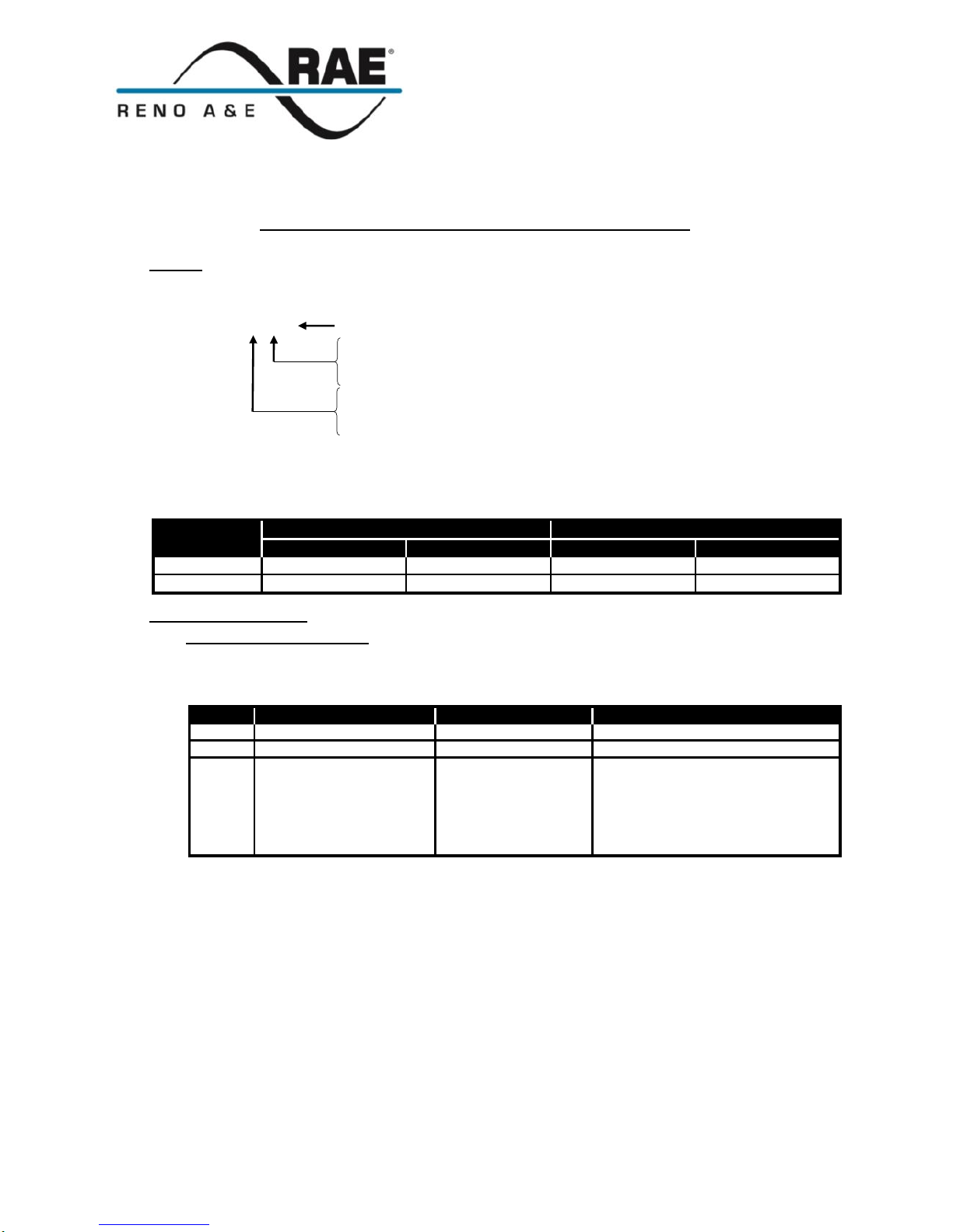
The detector is factory configured for either Fail-Safe or Fail-Secure operation (see unit side label). The output state of
each output relay in either Fail-Safe or Fail-Secure mode is listed in the table below.
Relay
Fail-Safe
Fail-Secure
Power Failure
Loop Failure
Power Failure
Loop Failure
A
Call
Call
No Call
No Call
B
No Call
No Call
No Call
No Call
II. Indicators and Controls
i. Power / Detect / Fail LEDs
The detector has one green and two red LED indicators that are used to provide an indication of the detector’s
power status, output state, and/or loop failure conditions. The table below lists the various indications and their
meanings.
Status
PWR (Power) LED
DET (Detect) LED
FAIL LED
Off
No power or low power
Output(s) Off
Loop OK
On
Normal power to detector
Output(s) On
Open Loop
Flash
N/A
4 Hz (50% duty cycle)
Two second timing
delay activated
1 Hz (50% duty cycle)
Shorted Loop
1 Hz (5% duty cycle)
Waiting for release of FREQ pushbutton to enter diagnostics mode
(See Failed Loop Diagnostics)
NOTE: If the supply voltage drops below 75% of the nominal level, the PWR LED will turn off, providing a
visual indication of low supply voltage. Model B detectors will operate with supply voltage as low as 70% of
nominal supply voltage.
ii. Frequency LEDs:
The four red LED indicators provide an indication of the current detector operating frequency.
iii. Front Panel Pushbutton Switches:
Two momentary contact pushbutton switches are used to control the following.
RESET - Push the front panel mounted pushbutton labeled RESET to reset the detector.
Page 2
Eberle Design, Inc.
3510 E Atlanta Avenue
Phoenix, AZ 85040,
Tel: (480) 968-6407
Fax: (602) 437-1996
www.renoae.com
Model B Series Rev. 03-14-2019 2 P/N 551-0202-02
FREQ - In situations where loop geometry forces loops to be located in close proximity to one another, it may be
necessary to select different frequencies for each loop to avoid loop interference, commonly known as crosstalk.
The front panel mounted pushbutton labeled FREQ can be used to configure the detector to operate at one of four
(4) frequencies corresponding to Low, Medium / Low, Medium / High, and High. Press the FREQ pushbutton to
toggle through and select one of the four frequency settings.
NOTE: After changing the frequency setting, the detector must be reset by pressing the front panel RESET
pushbutton.
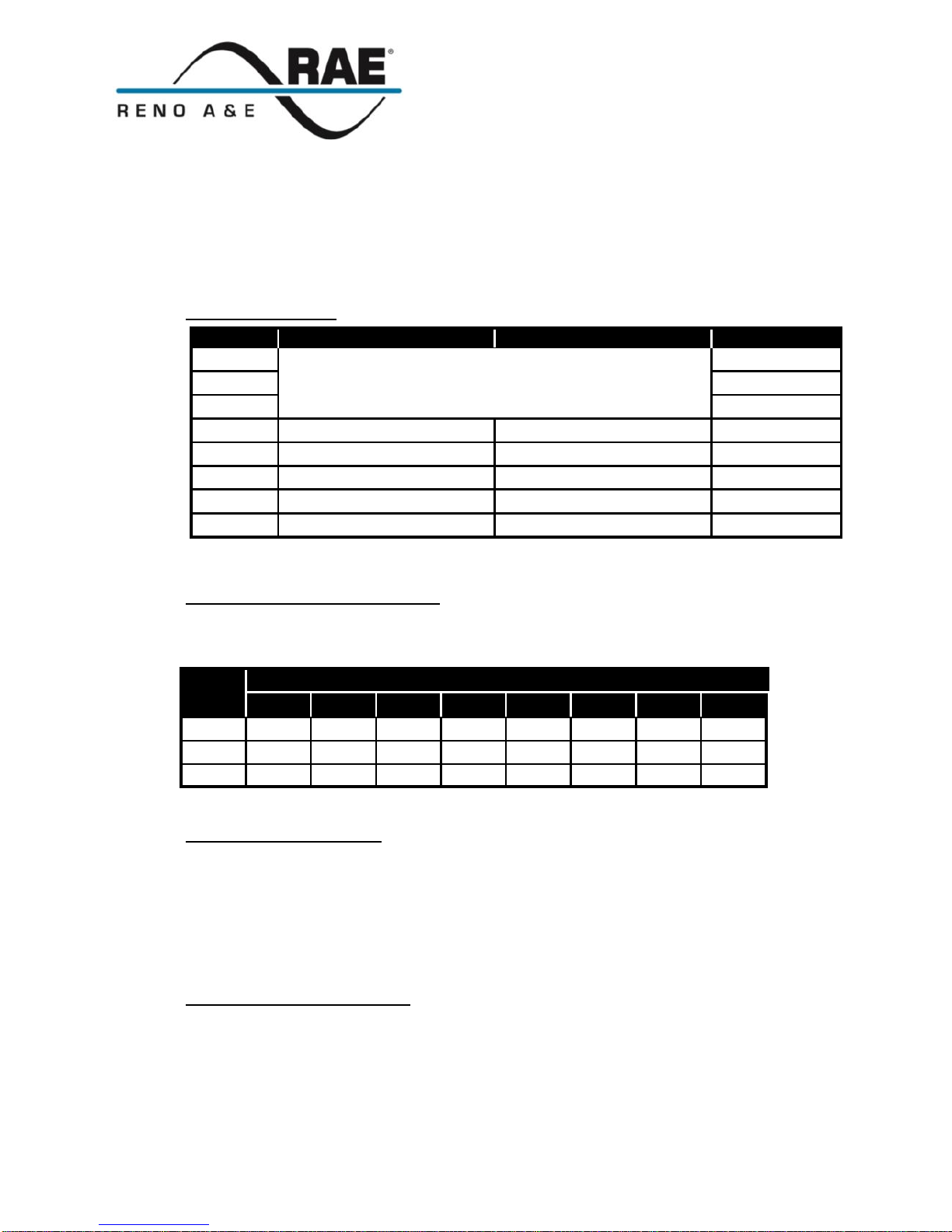
iv. Internal DIP Switches
Switch
ON
OFF
Factory Default
1
Sensitivity
(See Table under Sensitivity Section)
OFF
2
ON 3 ON
4
Two Second Delay
No Delay
OFF 5 Sensitivity Boost
No Boost
OFF *
6
Exit Pulse Relay B
Entry Pulse Relay B
OFF
7
Limited Presence
True PresenceTM
OFF
8
Pulse Mode Relay B
Presence Mode Relay B
ON **
* Sensitivity Boost (SB) models have DIP switch 5 set to the ON position.
** Dual Presence (DP) models have DIP switch 8 set to the OFF position.
Sensitivity (DIP Switches 1, 2, and 3)
DIP switches 1, 2, and 3 select one of the eight (8) sensitivity levels available as shown in the table below. 0 is the
lowest setting, 3 is normal, and 7 is the highest setting. Use the lowest sensitivity setting that will consistently
detect the smallest vehicle that must be detected. Do not use a sensitivity level higher than necessary.
Output Delay (DIP Switch 4)
A two second delay of Outputs A and B can be activated by setting DIP switch 4 to the ON position. Output delay
is the time the detector outputs are delayed after a vehicle first enters the loop detection zone. If the two second
Output Delay feature is activated, the output relays will only be turned on after two seconds have passed with a
vehicle continuously present in the loop detection zone. If the vehicle leaves the loop detection zone during the
two second delay interval, detection is aborted and the next vehicle to enter the loop detection zone will initiate a
new full two second delay interval. The detector provides an indication that a vehicle is being detected but that the
outputs are being delayed, by flashing the front panel DET LED at a four Hz rate with a 50% duty cycle. The
factory default setting is OFF (no Output Delay).
Sensitivity Boost (DIP Switch 5)
DIP switch 5 can be turned ON to increase sensitivity during the period of detection without changing the
sensitivity during the no detect period. The boost feature has the effect of temporarily increasing the sensitivity
setting by up to two levels. When a vehicle enters the loop detection zone, the detector automatically boosts the
sensitivity level. As soon as no vehicle is detected, the detector immediately returns to the original sensitivity
level. This feature is particularly useful in preventing dropouts during the passage of high bed vehicles. The
factory default setting is OFF (no Sensitivity Boost) unless sensitivity boost (SB) operation is specified, in which
case the factory default setting is ON (Sensitivity Boost).
Switch
Sensitivity
0 1 2
3 * 4 5
6
7
1
OFF
OFF
OFF
OFF *
ON
ON
ON
ON
2
OFF
OFF
ON
ON *
OFF
OFF
ON
ON
3
OFF
ON
OFF
ON *
OFF
ON
OFF
ON
* Factory default setting.
Page 3

Eberle Design, Inc.
3510 E Atlanta Avenue
Phoenix, AZ 85040,
Tel: (480) 968-6407
Fax: (602) 437-1996
www.renoae.com
Model B Series Rev. 03-14-2019 3 P/N 551-0202-02
Relay B Pulse Mode (DIP Switch 6)
Relay B is the pulse output. Its pulse output mode is controlled by DIP switch 6. Relay B can be configured to
output a single 250 millisecond pulse when a vehicle enters the loop detection zone (Pulse-on-Entry) or when a
vehicle leaves the loop detection zone (Pulse-on-Exit). Pulse-on-Entry is selected when DIP switch 6 is OFF.
Pulse-on-Exit is selected when DIP switch 6 is ON. DIP switch 6 has no effect on Relay A (the presence output).
The factory default setting is OFF (Pulse-on-Entry).
NOTE: The setting of this DIP switch has no effect on the output mode of Relay B if DIP switch 8 is set to the
OFF position (Presence Mode Relay B). For additional details, refer to the Relay B Output Mode section on
page 3.
Presence Hold Time (DIP Switch 7)
Output A always functions as a presence output. DIP switch 7 can be used to select one of two presence hold
times; Limited Presence or True PresenceTM. Both modes provide a Call output when a vehicle is present in
the loop detection zone. True PresenceTM is selected when DIP switch 7 is OFF. If DIP switch 7 is ON, Limited
Presence is selected. Limited Presence will typically hold the Call output for about one to three hours. True
PresenceTM will hold the Call as long as the vehicle is present in the loop detection zone provided that power is not
interrupted or the detector is not reset. True PresenceTM time applies only for normal size automobiles and trucks
and for normal size loops (approximately 12 ft2 to 120 ft2). The factory default setting is OFF (True PresenceTM
Mode).
Relay B Output Mode (DIP Switch 8)
Relay B has two modes of operation; Pulse or Presence. Its output mode is controlled by DIP switch 8. When set
to operate in Pulse Mode (DIP switch 8 ON), Relay B outputs a 250 millisecond pulse when a vehicle enters the
loop detection zone or when a vehicle leaves the loop detection zone. (See the Relay B Pulse Mode section on
page 2 for details.) When set to operate in Presence Mode (DIP switch 8 OFF), the output of Relay B is the same
as that of Relay A. (See the Presence Hold Time section above for details.) The factory default setting is ON
(Pulse Mode Relay B) unless dual presence (DP) operation is specified, in which case the factory default setting is
OFF (Presence Mode Relay B).
III. Call Memory
When power is removed for two seconds or less, the detector automatically remembers if a vehicle was present and a Call
was in effect. When power is restored, the detector will continue to output a Call until the vehicle leaves the loop
detection zone (loss of power or power dips of two seconds or less will not bring a gate arm down onto cars as they wait
at the gate).
IV. Failed Loop Diagnostics
The FAIL LED provides an indication of whether or not the loop is currently within tolerance. If the loop is out of
tolerance, the FAIL LED indicates whether the loop is shorted (one Hz flash rate) or open (steady ON). If and when the
loop returns to within tolerance, the FAIL LED will turn off to indicate that the loop fault condition has been corrected
and that the loop is once again within tolerance.
The Model B detector automatically stores the last loop failure type in non-volatile memory. To determine the type of
loop failure that has last occurred, press and hold the FREQ pushbutton for at least three seconds. When the FAIL LED
begins flashing at one Hz rate with a 5% duty cycle, release the FREQ pushbutton. The detector will then display the
last loop failure type detected (if any). This indication will be displayed one time for about fifteen seconds unless
terminated by pressing the RESET or FREQ pushbutton. The non-volatile memory used to store the last loop failure
type is automatically cleared each time it is interrogated.
Page 4

Eberle Design, Inc.
3510 E Atlanta Avenue
Phoenix, AZ 85040,
Tel: (480) 968-6407
Fax: (602) 437-1996
www.renoae.com
Model B Series Rev. 03-14-2019 4 P/N 551-0202-02
V. Pin Connections
Models B-3, B-4, and B-8 (Reno A&E Wiring Harness Model 802-4)
Pin
Wire Color
Function
1
Black
AC Line / DC +
2
White
AC Neutral / DC Common
3
Orange
Relay B, Normally Open (N.O.)
4
Green
No Connection
5
Yellow
Relay A, Common
6
Blue
Relay A, Normally Open (N.O.)
7
Gray
Loop
8
Brown
Loop
9
Red
Relay B, Common
10
Violet or Black / White
Relay A, Normally Closed (N.C.)
11
White / Green or Red / White
Relay B, Normally Closed (N.C.)
Models B-1, B-5, and B-35 (Reno A&E Wiring Harness Model 801-4)
Pin
Wire Color
Function
A
White
AC Neutral / DC Common
B
Brown
Relay A, Normally Open (N.O.)
C
Black
AC Line / DC +
D
Red
Loop
E
Orange
Loop
F
Yellow
Relay A, Common
G
Blue
Relay A, Normally Closed (N.C.)
H
Green
Chassis Ground
I
Violet
Relay B, Common
J
Gray
Relay B, Normally Open (N.O.)
NOTE: All pin connections listed above are with power applied, loop(s) connected, and no vehicle detected.
VII. Warnings
Separately, for each loop, a twisted pair should be created consisting of only two (2) loop wires running the entire
distance from the loop to the detector (including runs through all wiring harnesses) at a minimum of six (6) complete
twists per foot. For trouble free operation, it is highly recommended that all connections (including crimped
connectors) be soldered.
VIII. Loop Installation
The vehicle detection characteristics of an inductive loop detector are greatly influenced by the loop size and proximity to
moving metal objects such as gates. Vehicles such as small motorcycles and high bed trucks can be reliably detected if
the proper size loop is selected. If the loop is placed too close to a moving metal gate, the detector may detect the gate.
The diagram below is intended as a reference for the dimensions that will influence the detection characteristics.
General Rules
1. The detection height of a loop is 2/3 the shortest leg (A
or B) of the loop. Example: Short leg = 6 feet,
Detection Height = 2/3 x 6 feet = 4 feet.
A =
6 ft
9 ft
12 ft
15 ft
18 ft
21 ft
C =
3 ft
4 ft
4.5 ft
5 ft
5.5 ft
6 ft
2. As the length of leg A is increased, distance C must
also increase.
3. For reliable detection of small motorcycles, legs A and
B should not exceed 6 feet.
A B C
A = Loop dimension parallel to the gate
B = Loop dimension perpendicular to the gate
C = Distance of the loop from the gate
SLIDE GATE
Page 5

Eberle Design, Inc.
3510 E Atlanta Avenue
Phoenix, AZ 85040,
Tel: (480) 968-6407
Fax: (602) 437-1996
www.renoae.com
Model B Series Rev. 03-14-2019 5 P/N 551-0202-02
Loop Installation - Saw Cut Type
1 Mark the loop layout on the pavement. Remove sharp inside corners that can damage the loop wire insulation.
2 Set the saw to cut to a depth (typically 2" to 2.5") that ensures a minimum of 1" from the top of the wire to pavement
surface. The saw cut width should be larger than the wire diameter to avoid damage to the wire insulation when placed in
the saw slot. Cut the loop and feeder slots. Remove all debris from the saw slot with compressed air. Check that the
bottom of the slot is smooth.
3 It is highly recommended that a continuous length of wire be used to form the loop and feeder to the detector. Loop wire
is typically 14, 16, 18, or 20 AWG with cross-linked polyethylene insulation. Use a wood stick or roller to insert the wire to
the bottom of the saw slot (do not use sharp objects). Wrap the wire in the loop saw slot until the desired number of turns
is reached. Each turn of wire must lay flat on top of the previous turn.
4 The wire must be twisted together a minimum of 6 twists per foot from the end of the saw slot to the detector.
5 The wire must be held firmly in the slot with 1" pieces of backer rod every 1 to 2 feet. This prevents the wire from floating
when the loop sealant is applied.
6 Apply the sealant. The sealant selected should have good adhering properties with contraction and expansion
characteristics similar to those of the pavement material.
1
3
1/8" to 1/4" SAW SLOT
THE WIRE IS
CONTINUOUSLY WOUND
IN THE LOOP SAW SLOT
FOR THE REQUIRED
NUMBER OF TURNS (2
turns shown)
turn 2
turn 1
REMOVE SHARP
INSIDE CORNERS
FEEDER SLOT
END OF SAW CUT
4
THE WIRES MUST BE
TWISTED TOGETHER
6 TWISTS PER FOOT
FROM THE END OF
THE SAW CUT TO
THE DETECTOR
Recommended Loop Wire: Reno A&E LW-120 for 1/8" slots
Reno A&E LW-116-S for 1/4" slots
ROAD SURFACE
MIN
1"
SAW SLOT
SEALANT
BACKER ROD
1" piece spaced
about every 1'
LOOP WIRE
3 TURNS
2
6
5
LOOP PERIMETER
NUMBER OF TURNS
10 feet - 13 feet
5
14 feet - 26 feet
4
27 feet - 45 feet
3
46 feet - 100 feet
2
100 feet and up
1
 Loading...