

http://w
ww.renkus-heinz.com/support/software-support/rhaon/e-mail.html.
2
IC
Users Manual
INTRODUCTION
Congratulations on your purchase of a Renkus-Heinz RHAON Empowered digitally steered Iconyx ( IC Squared) loudspeaker system We hope
you enjoy it.
Your Iconyx IC Squared loudspeaker was carefully tested and inspected before leaving our
factory and should have arrived in perfect condition. Please carefully inspect the shipping
carton(s) and loudspeaker(s) for any noticeable damage, and if any damage is found, immediately notify the shipping company. Only you, the consignee, may institute a claim with the
carrier for any damage incurred during shipping. Be sure to save the carton(s) and all packing
material for the carrier’s inspection. It is also a good idea to save the carton and packing material even though the loudspeaker arrived in good condition. If you should ever need to ship the
loudspeaker, it should be shipped in its original factory packaging.
TECHNICAL SUPPORT
If you have any questions about IC Squared loudspeakers or encounter a problem designing,
installing, setting up or operating a RHAON system, please call our technical support staff at
949-588-9997 and ask the operator for technical support on RHAON. Call Monday through
Friday from 8:00 AM to 5:00 PM Pacifi c Time.
The latest information on RHAON Technical Support is always available online at
ww.renkus-heinz.com/support/software-support/rhaon/e-mail.html. You will also fi nd a support
request form at http://www.renkus-heinz.com/support/request-info/tech-info/index.html.
http://w
IC Squared Digitally Steerable Loudspeaker Systems
Your IC Squared loudspeaker system is a unique device that combines the advantages of point
source design with the control and fl exibility of digitally steerable line array technology.
Unlike traditional vertical line arrays that need to be curved to steer the sound, IC Squared arrays use digital control to steer the sound while the array remains a straight vertical line.
Individual transducer control maximizes the acoustical advantages of the design and producing
unsurpassed vertical pattern control. Individual sonic beams can be shaped and steered up or
down and their acoustical center placed anywhere within the array.
IC Squared loudspeakers are powerful and versatile. They can be used as a stand alone high
performance loudspeaker, in a small stack when additional control and output are needed or
fl own in large multi cabinet arrays when even more p@ower is needed.
Matching IC212S-R and IC118-R subwoofers can be used as a base for the array modules or used as a
suspension platform when the array modules and subwoofers are fl own.
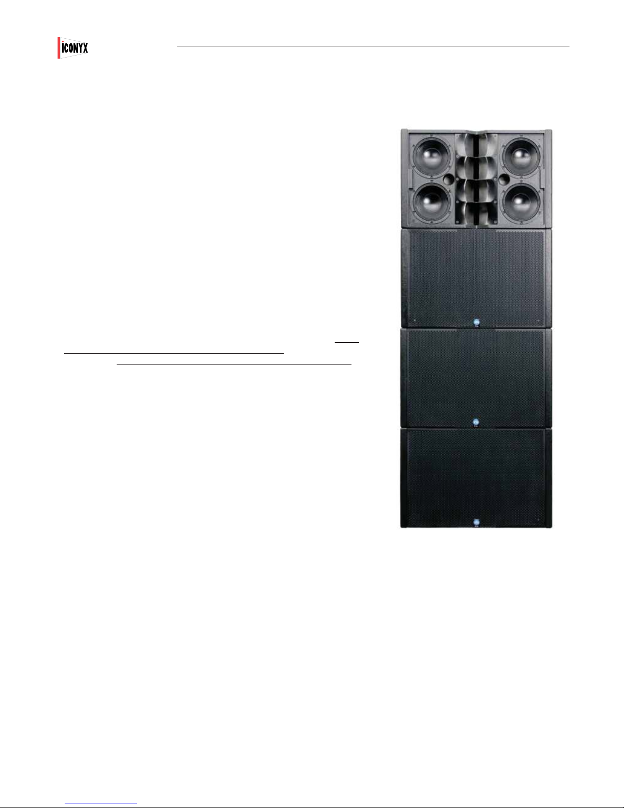
IC2 Array
Installation.
Your IC Squared system was designed to be easy to fl oor stack or to be suspended from a ceiling. Note that it was not designed to be mounted
directly on a wall. The amplifi ers are convection cooled and their heat sinks require at least several inches of separation from the nearest
surface.
The actual installation should be made either by or under the close supervision of someone experienced in installation techniques and rigging.
4

IC2-R Mobile Array Module Assembly
Floor Stacks
IC2-R mobile array modules and their matching subwoofers are often fl oor stacked
using the subwoofers as a mounting base for the array modules.
Typical fl oor stacks include two or three array modules plus one or two matching
subwoofers. Floor stacks can be built without the subwoofers, but the stack won’t bet
as stable as one built with one or two subwoofers as the base.
To assemble an IC2-R fl oor stack.
1. Remove the cabinet ( subwoofer or array module) that will be used as the base
for the array from its carton and place it into position.
2. Remove a second array module from its carton. Place it in position on top of the
fi rst cabinet making sure the steel channels on both ends of the cabinet are aligned
with the ones on the subwoofer.
3. Remove (pull out) the quick disconnect pins from the channels at the top
of the lower cabinet. Then use the knurled knobs on the top cabinet’s joining
bars to move the end of the bars down into the lower cabinet’s channels.
In other words, grab the knobs and one by one slide the joining bars in the
channels on the top cabinet down into the top of the channels on the lower
cabinet.
Users Manual
Typical Floor Stack
IC
2
4. After the joining bars from the top cabinet are slipped into the top of the
channels on the lower cabinet, secure them in place with the lower cabinet’s
quick disconnect pins. The lower cabinet’s joining bars should be left in their
position at the bottom of their channels unless and until they are needed to
add another array module.
5. Repeat the procedure with each of the four joining bars until the cabinets
are isecurely fastened together. Note that if a second subwoofer had been
included to form base, the two subwoofers would have been joined together
in the same fashion
Flying Arrays
The procedure for assembling fl ying arrays is similar to the one used to assemble
ground stacks, except that the order is reversed. Ground stacks are assembled from
the bottom up while fl own arrays are usually assembled from the top down using the
RHANG-IC2 Flybar assembly; see photo
To assemble an IC2-R fl ying array using the RHANG-IC2 Flybar:
1. Insert the 2 heavy attachment arms into the top of the metal channels on the array
module and secure them in place with the quick disconnect pins.
2. Attach the lifting device (chain hoist, fork lift, etc) you will use to raise the array to
the fl ybar. One commonly used arrangement is shackles and a sling.
Knurled Knob
Quick
Discon-
nect
Side View Close up
3. Raise the array high enough to let you roll or slide the next cabinet into position
beneath it. Lower the array assembly into position on the second cabinet and secure
it into position with the joining bars and quick disconnect pins.
4. Repeat the procedure until the array is complete.
RHANG-IC2 Fly Bar
5

2
IC
Users Manual
IC2-FR Assembly (Fixed Installation)
RHANG-IC2 Flybar
IC2-FR Array Module
IC Squared array modules and their matching subwoofers are often fl oor stacked using the subwoofers as a
mounting base for the array modules.
Typical fl oor stacks include two or three array modules plus one or two matching subwoofers. Floor stacks can
be built without the subwoofers, but the stack isn’t as stable as one built with one or two subwoofers as the
base.
To assemble an IC2-FR fl oor stack:
1. Remove the loudspeaker (subwoofer or array module) that will be used as the base and its associated
hardware (M10 bolts, joining biscuits and wrench) from their shipping carton. Place the loudspeaker in position.
2. Install the four joining biscuits in the metal channels on the ends of the cabinet using the M10 bolts with the
Nylon thread lock included in the hardware package and tighten with the tool provided. The circular hole on the
end of the biscuit marked “1” is the correct hole to use.
2. Remove another array module and its associated hardware from their carton. Place the array module in
position on top of the fi rst cabinet making sure the steel channels on both ends of the cabinet are aligned with
the joining biscuits on the lower cabinet.
3. Insert and tighten the M10 bolts with the Nylon thread lock using the tool provided
4 Repeat the procedure until all of the array modules are securely fastened together. Note that if a second
subwoofer had been included to form the base, the two subwoofers would have been joined together in the
same fashion
Flying Arrays
The procedure for assembling fl ying IC2-FR arrays is similar to the one used to assemble ground stacks,
except that the order is reversed. Ground stacks are assembled from the bottom up while fl own arrays are
usually assembled from the top down using the RHANG-IC2 Flybar assembly to fl y the fi rst array module or
subwoofer.
To assemble an IC2-FR fl ying array using the RHANG-IC2 Flybar
IC2-FR
Connecting Biscuit
1. Insert the fl ybar’s 2 heavy attachment arms into the metal channels on the top module and secure them in
place using the M10 bolts with the Nylon thread lock and the tool provided in the hardware package.
2. Attach the lifting device (chain hoist, fork lift, etc) you will use to raise the array to the fl ybar. One commonly
used arrangement is shackles and a sling.
3. Raise the array high enough to let you roll or slide the next array module into position beneath it. Insert the
joining biscuits into the module being added and insert and tighten the M10 bolts with the Nylon thread lock
4. Lower the array array assembly into position on the array module being added and secure it into position by
inserting the and tightening the M10 bolts with the Nylon thread lock
5. Repeat the procedure until the array is complete. Then check to make sure all the M10 bolts are tight.
6
IC2-FR 4-stack array

IC2-FR-WR Assembly (Weather Resistant Fixed Installation)
Users Manual
IC
2
1) Unpack the individual enclosures and associated hardware.
2) Pre stage your array on a clean non-abrasive padded surface such as carpet by laying
the enclosures in position face down on the carpet. A small gap of less than 1/4” (6.35 mm)
between the enclosures is normal.
3) Unpack the metal hanging hardware/side straps, the “NEW” M10 x 50mm bolts the wrench
and the liquid thread lock
4) Remove and discard the eight M10 x 35mm bolts on from each end of the enclosure. Do
not remove the M10 bolts from the top and bottom of the enclosure.
5) Hold the hanging hardware in place against the side of the array,inserrt and fi nger tighten
the new M10 x 50mm bolts in place. Be certain to use the liquid tread locker to ensure the
bolts to not back out during operation and create a water tight seal.
6) Adjust the individual enclosures placement as necessary to ensure the bolts align properly.
If the enclosures are not aligned properly there is a risk of cross threading the bolts.
7) Repeat steps 5 & 6 for each side strap.
8) Tighten all M10 bolts to their fi nal tightness using the tool provided with them
9) Done.
Do not remove these bolts
Hang Points
Hang points
Pull back points
Completed weather resistant array
with side straps and front grilles
in place
7

2
IC
Users Manual
Address Number Verifi cation
All that remains is to verify that the individual IC2-R modules are properly identifi ed in the RHAON network.
IC Squared offers two methods of handling multi cabinet line arrays; the conventional Master/Slave arrangement and an All Master
approach. For small systems having 4 or fewer Array modules, either method can be used. All arrays having 5 or more modules must
use the All Master approach.
In the conventional approach one module serves as the Master and all the other modules are designated Slaves. The incoming signal
and power lines terminate in the Master module and are then linked to the Slave modules with jumper cables. The Master/Slave dip
switches located on each modules input panel are used to set up the assignment. See page 53 for a detailed view of the input panel.
Normally the bottom module will be the Master and the other modules will be the Slaves numbered 1, 2 & 3 in ascending order. However, as long as the switches are set properly any module can be designated as the Master. You may, for example, designate the top
module as the Master to allow you to bring the signal cables into the top of the array. Set the switches in accordance with the drawing
shown below.
In single cabinet usage and when using the All Master method of control, the dip switches should always be set to the Master setting
(“00”).
Be aware that certain functions will be disabled on the Slave modules as their control has been turned over to the Master module.
Preset Up, Preset Down, Preset Enter , Input Pad, Volume Up & Volume Down, AES/EBU Input and Mute functions are all controlled
only by the controls on the Master module. Signal cables must be brought into the Master module. Jumper cable are then used to link
the modules together. AC power needs to be brought into each module.
Note that if you connected power to the modules before setting the dip switches, you will need to disconnect power and reconnect it
before the dip switch settings will take effect.
Master
Setting
1
Slave #1
Setting
2
Slave #2
Setting
3
Slave #3
Setting
4
In the All Master approach, all modules are treated as Masters and there are no Slaves. The dip switches are all set to the Master
setting and individual signal cables are brought into each module. More details on setting up and using the all Master approach are
provided in the Beam Steering section of this document.
8
 Loading...