


Bedienungsanleitung
Show Design 2 DMX-Controller
Best.-Nr. 1359970 Seite 2 - 31
Operating Instructions
Show Design 2 DMX-Controller
Item No. 1359970 Page 32 - 61
Notice d´emploi
Contrôleur DMX Show Design 2
N° de commande 1359970 Page 62 - 91
Gebruiksaanwijzing
Show Design 2 DMX-controller
Bestelnr. 1359970 Pagina 92 - 121

Inhaltsverzeichnis
Seite
1. Einführung ............................................................................................................................................................3
2. Lieferumfang ........................................................................................................................................................3
3. Bestimmungsgemäße Verwendung ................................................................................................................
4. Symbolerklärung .................................................................................................................................................4
5. Sicherheitshinweise ...........................................................................................................................................5
6. Featurebeschreibung .........................................................................................................................................6
7. Anschluss- und Bedienelemente .....................................................................................................................
8. Aufstellung/Montage..........................................................................................................................................8
9. Anschluss .............................................................................................................................................................9
a) Anschluss der Lichteekte .........................................................................................................................9
b) Netzanschluss ..............................................................................................................................................10
10. Grundlegende Bedienung
11. Adressierung und Grundeinstellung ...............................................................................................................
a) Vorprogrammierte Adressierung der Lichteekte .................................................................................11
b) Individuelle Adressierung der Lichteekte .............................................................................................12
c) DMX-Kanalzuweisung ................................................................................................................................13
d) Invertierung der Steuerkanäle ..................................................................................................................15
e) FADE-Funktion für Lichteektgeräte ........................................................................................................15
f) Kopierfunktion für Geräteeinstellungen ..................................................................................................16
12. Lichtszenen 16
a) Manuelle Einstellung ..................................................................................................................................16
b) Bewegungsmuster und Farbeekte .........................................................................................................17
c) Speicherung .................................................................................................................................................17
d) Abruf von Lichtszenen ................................................................................................................................18
e) FADE-Funktion ..............................................................................................................................................18
f) Löschen von Lichtszenen ...........................................................................................................................19
13. Lauflichtfunktionen ............................................................................................................................................19
a) Programmieren und speichern .................................................................................................................19
b) Einfügen von Lichtszenen ..........................................................................................................................20
c) Abruf von Lauflichtfunktionen ...................................................................................................................20
d) FADE-Funktion ..............................................................................................................................................21
e) Manuelle Kontrolle ......................................................................................................................................22
f) Löschen von Lauflichtfunktionen ..............................................................................................................22
14. Black Out-Funktion ............................................................................................................................................
15. Systemeinstellungen .........................................................................................................................................23
a) Menübedienung ...........................................................................................................................................23
b) Erklärung der einzelnen Menüpunkte ......................................................................................................23
16. Firmware-Aktualisierung ..................................................................................................................................27
17. Wartung ...............................................................................................................................................................28
18. Behebung von Störungen .................................................................................................................................
19. Handhabung........................................................................................................................................................30
20. Entsorgung ..........................................................................................................................................................30
21. Technische Daten ..............................................................................................................................................
.................................................................................................................................11
4
7
11
22
29
31
2

1. Einführung
Sehr geehrte Kundin, sehr geehrter Kunde,
wir bedanken uns für den Kauf dieses Produkts.
Dieses Produkt erfüllt die gesetzlichen nationalen und europäischen Anforderungen. Um diesen Zustand
zu erhalten und einen gefahrlosen Betrieb sicherzustellen, müssen Sie als Anwender diese Bedienungs
anleitung beachten!
Diese Bedienungsanleitung gehört zu diesem Produkt. Sie enthält wichtige Hinweise zur Inbe-
triebnahme und Handhabung. Achten Sie hierauf, auch wenn Sie dieses Produkt an Dritte weitergeben. Heben Sie deshalb diese Bedienungsanleitung zum Nachlesen auf!
Bei technischen Fragen wenden Sie sich bitte an:
Deutschland: www.conrad.de/kontakt
Österreich: www.conrad.at
www.business.conrad.at
Schweiz: www.conrad.ch
www.biz-conrad.ch
2. Lieferumfang
• DMX-Controller
• Netzteil
• Bedienungsanleitung
-
3
3. Bestimmungsgemäße Verwendung
Der DMX-Controller dient zur Steuerung von DMX-Lichteekten und ähnlichen Geräten mit DMX-Steuerung in Lightshow-Anlagen, Partyräumen etc.
Die Stromversorgung dieses Produktes darf nur über das beiliegende Netzteil erfolgen. Das Netzteil ist nur
für den Anschluss an Netzsteckdosen mit 100-240 V / 50/60 Hz Wechselspannung des öentlichen Strom
versorgungsnetzes zugelassen.
Eine Verwendung ist nur in geschlossenen Räumen, also nicht im Freien erlaubt. Der Kontakt mit Feuchtig
keit, z.B. im Badezimmer u.ä. ist unbedingt zu vermeiden.
Eine andere Verwendung als zuvor beschrieben führt zur Beschädigung dieses Produktes, darüber hinaus
ist dies mit Gefahren, wie z.B. Kurzschluss, Brand, elektrischer Schlag etc. verbunden.
Das gesamte Produkt darf nicht geändert bzw. umgebaut und das Gehäuse nicht geönet werden.
Beachten Sie alle Sicherheitshinweise dieser Bedienungsanleitung!
4. Symbolerklärung
Dieses Zeichen auf dem Gerät weist den Benutzer darauf hin, dass er vor der Inbetriebnahme
des Gerätes diese Bedienungsanleitung lesen und beim Betrieb beachten muss.
Das Symbol mit dem Blitz im Dreieck wird verwendet, wenn Gefahr für Ihre Gesundheit besteht,
z.B. durch elektrischen Schlag. Im Gerät befinden sich keine vom Benutzer zu wartenden Teile.
Önen Sie das Gerät deshalb nie.
-
-
Wichtige Hinweise, die unbedingt zu beachten sind, werden in dieser Bedienungsanleitung
durch das Ausrufezeichen gekennzeichnet.
Das Symbol mit dem Pfeil ist zu finden, wenn besondere Tipps und Hinweise zur Bedienung ge-
geben werden.
Dieses Symbol weist darauf hin, dass das Produkt nur in Innenräumen verwendet werden darf.
4

5. Sicherheitshinweise
Bei Schäden, die durch Nichtbeachten dieser Bedienungsanleitung verursacht werden, er-
lischt die Gewährleistung/Garantie. Für Folgeschäden übernehmen wir keine Haftung.
Bei Sach- oder Personenschäden, die durch unsachgemäße Handhabung oder Nichtbeachten
der Sicherheitshinweise verursacht werden, übernehmen wir keine Haftung. In solchen Fällen
erlischt die Gewährleistung/Garantie.
Sehr geehrte Kundin, sehr geehrter Kunde: Die folgenden Sicherheits- und Gefahrenhinweise
dienen nicht nur zum Schutz des Gerätes, sondern auch zum Schutz Ihrer Gesundheit. Lesen Sie
sich bitte die folgenden Punkte aufmerksam durch:
• Um eine sachgemäße Inbetriebnahme zu gewährleisten, lesen Sie vor Gebrauch unbedingt
diese Bedienungsanleitung mit den Sicherheitshinweisen vollständig und aufmerksam durch.
• Prüfen Sie vor der Inbetriebnahme das Gerät und das Netzteil auf Schäden. Falls solche vor
liegen sollten, nehmen Sie es nicht in Betrieb, sondern wenden Sie sich an eine Fachkraft oder
unseren Service.
• Aus Sicherheitsgründen ist das eigenmächtige Umbauen und/oder Verändern des Produktes
nicht gestattet.
• Als Spannungsquelle für das Netzteil darf nur eine ordnungsgemäße Netzsteckdose
(100-240 V / 50/60 Hz) des öentlichen Versorgungsnetzes verwendet werden. Der DMX-Controller selbst darf nur über das beiliegende Netzteil mit Energie versorgt werden.
• Der DMX-Controller ist auch im ausgeschalteten Zustand mit dem Netz verbunden. Um ihn
vollständig vom Netz zu trennen muss das Netzteil aus der Netzsteckdose gezogen werden.
• Sollte das Netzteil oder dessen Anschlussleitung Beschädigungen aufweisen, so berühren Sie
es nicht. Schalten Sie zuerst die zugehörige Netzsteckdose stromlos (z.B. über den zugehö
rigen Sicherungsautomaten und FI-Schalter) und ziehen Sie danach das Netzteil vorsichtig aus
der Netzsteckdose.
• Ersetzen Sie nie eine schadhafte Anschlussleitung des Netzteils. Sollte die Anschlussleitung
beschädigt sein, ist das Netzteil unbrauchbar und muss entsorgt werden. Eine Reparatur ist
nicht zulässig.
• Fassen Sie das Netzteil niemals mit feuchten oder nassen Händen an. Es besteht die Gefahr
eines lebensgefährlichen elektrischen Schlages!
• Alle Personen, die dieses Produkt bedienen, installieren, aufstellen, in Betrieb nehmen oder
warten müssen entsprechend ausgebildet und qualifiziert sein und diese Bedienungsanleitung
beachten.
• Geräte, die an Netzspannung betrieben werden gehören nicht in Kinderhände. Lassen Sie
deshalb beim Betrieb des Gerätes in Anwesenheit von Kindern besondere Vorsicht walten,
insbesondere wenn diese versuchen Gegenstände durch Gehäuseönungen in ein Gerät zu
stecken. Es besteht die Gefahr eines lebensgefährlichen elektrischen Schlags.
• Stellen Sie keine Gefäße mit Flüssigkeiten, z.B. Gläser, Eimer, Vasen oder Pflanzen, auf das
Gerät oder in seine unmittelbare Nähe. Flüssigkeiten könnten ins Gehäuseinnere gelangen
und dabei die elektrische Sicherheit beeinträchtigen. Außerdem besteht höchste Gefahr eines
Brandes oder eines lebensgefährlichen elektrischen Schlages! Schalten Sie in einem solchen
Fall die zugehörige Netzsteckdose stromlos (z.B. Sicherungsautomat und FI-Schalter abschal
ten) und ziehen Sie danach das Netzteil aus der Netzsteckdose. Das Produkt darf danach nicht
mehr betrieben werden, bringen Sie es in eine Fachwerkstatt.
-
-
-
5

• Setzen Sie das Gerät keinen hohen Temperaturen, Tropf- oder Spritzwasser, starken Vibrationen, sowie hohen mechanischen Beanspruchungen aus.
• Stellen Sie keine oenen Brandquellen wie brennende Kerzen auf oder direkt neben dem Gerät
ab.
• Wenden Sie sich an eine Fachkraft, wenn Sie Zweifel über die Arbeitsweise, die Sicherheit
oder den Anschluss des Produktes haben.
• Betreiben Sie das Gerät nicht unbeaufsichtigt.
• Benutzen Sie das Gerät nur in gemäßigtem Klima, nicht in tropischem Klima.
• Lassen Sie Verpackungsmaterial nicht achtlos liegen. Es könnte für Kinder zu einem gefähr
lichen Spielzeug werden.
• In gewerblichen Einrichtungen sind die Unfallverhütungsvorschriften des Verbandes der ge
werblichen Berufsgenossenschaften für elektrische Anlagen und Betriebsmittel zu beachten.
• Sollten Sie sich über den korrekten Anschluss nicht im Klaren sein oder sollten sich Fragen
ergeben, die nicht im Laufe der Bedienungsanleitung abgeklärt werden, so setzen Sie sich
bitte mit unserer technischen Auskunft oder einem anderen Fachmann in Verbindung.
6. Featurebeschreibung
• Geeignet für bis zu 32 Lichteekte mit je 18 Kanälen
• RDM-fähig
• 16 Kanalfader und zwei Drehregler (PAN/TILT)
• Alle Kanäle frei zuweisbar
• 32 Lichtszenen (alle Lichtszenen können gleichzeitig aktiviert werden)
• 32 Lauflichtfunktionen mit bis zu 100 Lichtszenen (bis zu 5 Lauflichtfunktionen simultan aktivierbar)
• 9 Programme für die Bewegung von Moving Heads und Scannern
• 7 Programme für die Farbsteuerung von Lichteekten
• Lauflichtfunktionen manuell, automatisch oder musikgesteuert abspielbar
• Fader und Drehregler invertierbar
• Black Out-Taste
• Sound-to-Light-Steuerung über integriertes Mikrofon
• Beleuchtetes LC-Display
• Rackeinbau möglich (3HE)
• USB-Schnittstelle für Firmware Update und Datensicherung von Lightshows
-
-
6
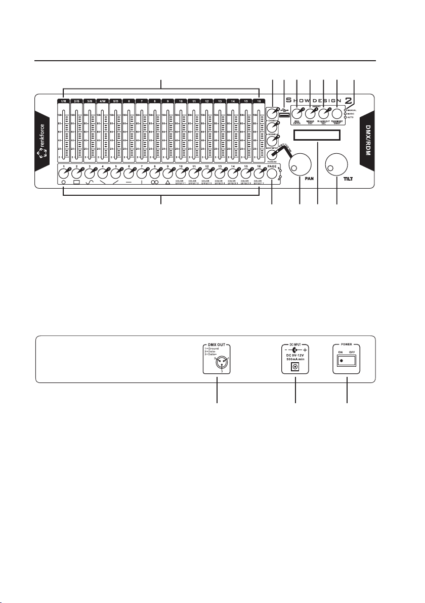
7. Anschluss- und Bedienelemente
1 2 3 4 5 6 7
9 10 11 1
2 13
8
15
16
14
(1) Kanalfader
(2) Funktionstasten CHASE/SCENE/MOVEMENT/FIXTURE
(3) USB-Schnittstelle
(4) Taste REC/ENTER
(5) Taste MENUS/ESC
(6) Taste BLACK OUT/DEL
(7) Taste RUN MODE/SWAP
(14) Anschluss DMX OUT
(15) Anschluss DC INPUT
(16) Schalter POWER
(8) Betriebsartanzeige
(9) Auswahltasten 1-16
(10) Taste PAGE
(11) Drehregler PAN
(12) Display
(13) Drehregler TILT
7
8. Aufstellung/Montage
Achten Sie bei der Aufstellung/Montage auf ausreichende Belüftung.
Stellen Sie das Gerät nicht auf weiche Untergründe, wie z.B. Teppiche oder Betten etc.
Außerdem darf die Luftzirkulation nicht durch Gegenstände wie Zeitschriften, Tischdecken,
Bohren Sie keine Löcher oder drehen Sie keine Schrauben zur Befestigung des Gerätes in das
Beim Aufstellen des Gerätes ist auf einen sicheren Stand und auf einen stabilen Untergrund
Beachten Sie beim Aufstellen des Gerätes, dass die Anschlusskabel nicht gequetscht oder
Verlegen Sie Kabel immer so, dass niemand über diese stolpern oder an ihnen hängen bleiben
Achten Sie bei der Auswahl des Aufstellortes darauf, dass Einstrahlung von direktem, inten
Es dürfen sich keine Geräte mit starken elektrischen oder magnetischen Feldern, wie z.B.
• Stellen Sie das Gerät auf einer ebenen Fläche auf.
• Bei Bedarf kann das Gerät auch mit den Bohrungen in der Frontplatte in einer Arbeitsplatte, einem Rack
Vorhänge o.ä. behindert werden. Dies verhindert die Wärmeabfuhr des Produkts und kann zur
Überhitzung führen (Brandgefahr).
Gehäuse, dadurch kann das Gerät beschädigt und in der Sicherheit beeinträchtigt werden.
zu achten. Durch ein Herunterfallen des DMX-Controllers besteht die Gefahr, dass Personen
verletzt werden.
durch scharfe Kanten beschädigt werden.
kann. Es besteht Verletzungsgefahr.
sivem Sonnenlicht, Vibrationen, Staub, Hitze, Kälte und Feuchtigkeit vermieden werden müs-
sen.
Transformatoren, Motoren, schnurlose Telefone, Funkgeräte usw. in direkter Nähe befinden, da
diese das Gerät beeinflussen können.
Stellen Sie das Gerät niemals ohne ausreichenden Schutz auf wertvolle oder empfindliche Mö-
beloberflächen.
o.ä. befestigt werden.
-
8
9. Anschluss
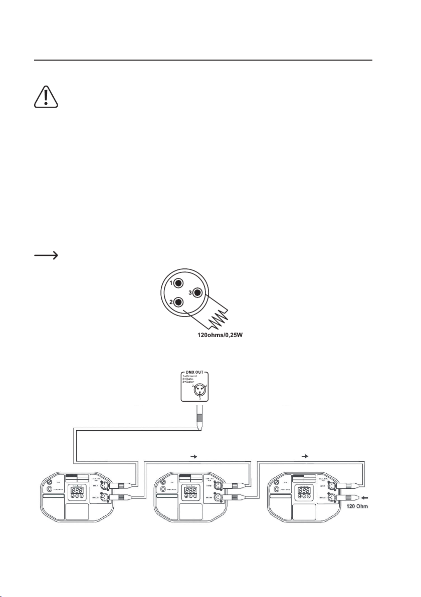
a) Anschluss der Lichteekte
Das Gerät ist ausschließlich zum Anschluss an DMX-Geräte mit DMX-512-Protokoll vorgese-
hen.
Es können max. 32 Geräte in einer DMX-Kette betrieben werden, da ansonsten der Controller
überlastet wird.
Die maximale Gesamtlänge der DMX-Kette sollte 300 m nicht überschreiten.
Bei der Verwendung von XLR-Mikrofonkabeln kann es zu Störungen bei der DMX-Signalüber-
tragung kommen. Bitte verwenden Sie in diesem Fall spezielle DMX-Hochfrequenzleitungen.
• Verbinden Sie den Anschluss DMX OUT (14) mit dem DMX-Eingang des ersten DMX-Lichteektes.
• Verbinden Sie den DMX-Ausgang des ersten DMX-Lichteektes mit dem DMX-Eingang des nachfol
genden Gerätes.
• Verfahren Sie mit den übrigen DMX-Lichteekten wie oben beschrieben.
• Stecken Sie in den DMX-Ausgang des letzten Gerätes der DMX-Kette einen Stecker mit einem
120 Ohm/0,25 W-Abschlusswiderstand (zwischen Pin2 und Pin3) ein.
Pinbelegung des DMX-Anschlusses: Pin1 = Masse / Pin2 = (-) / Pin3 = (+).
-
Anschlussbeispiel einer DMX-Kette:
9

b) Netzanschluss
Die Netzsteckdose, an die das Netzteil angeschlossen wird, muss leicht erreichbar sein, damit
das Netzteil im Fehlerfall schnell und einfach von der Netzstromversorgung getrennt werden
kann.
Lassen Sie die Leitung des Netzteils nicht mit anderen Leitungen in Kontakt kommen.
Seien Sie vorsichtig beim Umgang mit Netzleitungen und Netzanschlüssen. Netzspannung kann
lebensgefährliche elektrische Schläge verursachen.
Lassen Sie Kabel nicht frei herumliegen, sondern verlegen Sie sie fachmännisch um Unfallge
fahren zu vermeiden.
Achten Sie vor dem Einstecken des Netzteils darauf, dass die am Netzteil angegebene Geräte
spannung mit der verfügbaren Netzspannung übereinstimmt. Sollte die Angabe nicht mit der
zur Verfügung stehenden Netzspannung übereinstimmen, schließen Sie das Netzteil nicht an.
Bei einer falschen Versorgungsspannung kann es zu irreparablen Schäden am Netzteil bzw. am
DMX-Controller und zu Gefahren für den Benutzer kommen.
Überzeugen Sie sich davon, dass der DMX-Controller ausgeschaltet ist (Schalter POWER (16) in
Stellung O bzw. OFF bringen), bevor Sie ihn mit der Stromversorgung verbinden.
• Verbinden Sie die Anschlussleitung des Netzteils mit dem Anschluss DC INPUT (15) am DMX-Controller.
• Stecken Sie das Netzteil in eine Wandsteckdose.
• Der DMX-Controller wird mit dem Schalter POWER (16) ein- und ausgeschaltet:
Stellung O bzw. OFF: Gerät ausgeschaltet
Stellung I bzw. ON: Gerät eingeschaltet).
-
-
10

10. Grundlegende Bedienung
• Die Kanalfader (1) und die Drehregler PAN (11) und TILT (13) beeinflussen die DMX-Kanäle der Lichteffekte.
• Die Funktionstasten CHASE/SCENE/MOVEMENT/FIXTURE (2) legen fest, was mit den Auswahltasten
1-16 (9) ausgewählt wird.
CHASE aktiviert die Auswahl der 32 Lauflichtfunktionen
SCENE aktiviert die Auswahl der 32 Lichtszenen
MOVEMENT aktiviert die Auswahl der 9 Programme für Movingheads bzw. der 7 Programme für Lichtef
fekte
FIXTURE aktiviert die Auswahl der 32 Lichteekte
• Mit der Taste PAGE (10) wird die Ebene A bzw. B für die Auswahltasten 1-16 (9) umgeschaltet.
Ebene A (LED A leuchtet) > Funktionen 1-16
Ebene B (LED B leuchtet) > Funktionen 17-32
11. Adressierung und Grundeinstellung
a) Vorprogrammierte Adressierung der Lichteekte
Der DMX-Controller weist den 32 codierbaren Lichteekten die Startadressen in 18er-Schritten zu. Codieren Sie deshalb die Startadressen Ihrer Lichteekte ebenfalls in 18er-Schritten, da ansonsten eine individuelle Adressierung der Startadressen erforderlich ist (siehe „Individuelle Adressierung der Lichteekte“
im nächsten Abschnitt).
Lichteekt Startadresse
1 001
2 019
3 037
4 055
5 073
6 091
7 109
8 127
9 145
10 163
11 181
Lichteekt Startadresse
12 199
13 217
14 235
15 253
16 271
17 289
18 307
19 325
20 343
21 361
22 370
Lichteekt Startadresse
23 397
24 415
25 433
26 451
27 469
28 487
29 505
30 frei
31 frei
32 frei
-
11
Wenn Sie mehreren Lichteekten die gleiche Startadresse zuweisen, arbeiten sie synchron.
Den Lichteekten 1-29 sind also jeweils 18 DMX-Kanäle zugewiesen (z.B. Lichteekt 1 = DMX-
Den Lichteekten 30-32 wurden noch keine Startadresse zugewiesen. Dies kann jedoch manuell
Kanal 1-18, Lichteekt 2 = DMX-Kanal 19-36 usw.).
erfolgen (siehe „Individuelle Adressierung der Lichteekte“).
b) Individuelle Adressierung der Lichteekte
Die oben beschriebene Zuweisung der Startadressen kann auch individuell verändert werden.
• Drücken Sie die Taste MENUS/ESC (5) etwa zwei Sekunden lang, um in das Menü zu gelangen.
• Das Display (12) zeigt den ersten Menüpunkt „01. Patch fixture“ an (ist dies nicht der Fall, bitte mit dem
Drehregler PAN (11) diesen Punkt anwählen).
• Drücken Sie die Taste REC/ENTER (4), das Display (12) zeigt PLEASE SELECT FIXTURE.
• Drücken Sie die Auswahltaste 1-16 (9) des Lichteekts, dessen DMX-Startadresse verändert werden
soll.
Um die Lichteekte 1-16 zu wählen, muss die Ebene A mit der Taste PAGE (10) gewählt werden.
Für die Lichteekte 17-32 muss die Ebene B mit der Taste PAGE (10) gewählt werden.
• Im Display (12) wird der gewählte Lichteekt (FIX) und die zugewiesene DMX-Startadresse (ADR) ange
zeigt.
Wenn dem Lichteekt noch keine DMX-Startadresse zugewiesen ist (Lichteekt 30-32), zeigt das
Display (12) NO PATCH ADRESS an.
• Stellen Sie mit dem Drehregler PAN (11) die gewünschte DMX-Startadresse für den gewählten Lichtef
fekt ein.
Wenn eine bereits vergebene Adresse gewählt wird, zeigt das Display (12) neben der Adresse
ein Ausrufezeichen an.
• Drücken Sie die Taste REC/ENTER (4), um die Einstellung zu speichern. Alle LEDs blinken kurz auf, um die
erfolgreiche Speicherung anzuzeigen.
• Wiederholen Sie den beschriebenen Vorgang bei Bedarf, um andere Lichteekte neu zu adressieren.
• Nachdem Sie alle Änderungen durchgeführt haben, drücken Sie die Taste MENUS/ESC (5) etwa zwei
Sekunden lang, um das Menü wieder zu verlassen.
-
-
12
c) DMX-Kanalzuweisung
Die einzelnen DMX-Steuerkanäle Ihrer Lichteekte müssen nun noch den Steuerkanälen (Kanalfader und
Drehregler) des DMX-Controllers zugewiesen werden.
Die DMX-Kanalbelegung Ihrer Lichteekte finden Sie in den jeweiligen Bedienungsanleitungen.
Wird dies nicht durchgeführt, können die integrierten Programme für Moving Heads bzw. Scanner und für Lichteekte nicht funktionieren.
Folgende Kanalfader-Belegungen sind am DMX-Controller voreingestellt:
Kanalfader DMX-Kanal
1/R 1
2/G 2
3/B 3
4/W 4
5/D 5
6 6
7 7
8 8
9 9
1/R Helligkeit rot für Lichteekte
2/G Helligkeit grün für Lichteekte
3/B Helligkeit blau für Lichteekte
4/W Helligkeit weiß für Lichteekte
5/D Gesamthelligkeit für Lichteekte
PAN Drehbewegung für Moving Heads
TILT Schwenkbewegung für Moving Heads
Kanalfader DMX-Kanal
10 10
11 11
12 12
13 13
14 14
15 15
16 16
PAN 17
TILT 18
Wenn Sie einen Moving Head oder Scanner angeschlossen haben, müssen dessen Kanäle für PAN und
TILT den Kanälen 17 und 18 des DMX-Controllers zugewiesen werden.
Wenn Sie einen Lichteekt angeschlossen haben, müssen dessen Kanäle für die Farb- und Gesamthellig
keit den Kanälen 1-5 zugewiesen werden.
• Drücken Sie die Taste MENUS/ESC (5) etwa zwei Sekunden lang, um in das Menü zu gelangen.
• Das Display (12) zeigt den ersten Menüpunkt „01. Patch fixture“ an (ist dies nicht der Fall, bitte mit dem
Drehregler PAN (11) diesen Punkt anwählen).
• Drücken Sie die Taste REC/ENTER (4), das Display (12) zeigt PLEASE SELECT FIXTURE.
• Drücken Sie die Auswahltaste 1-16 (9) des Lichteekts, dessen Kanalzuordnung verändert werden soll.
Um die Lichteekte 1-16 zu wählen, muss die Ebene A mit der Taste PAGE (10) gewählt werden.
Für die Lichteekte 17-32 muss die Ebene B mit der Taste PAGE (10) gewählt werden.
13
-

• Wählen Sie mit der Taste RUN MODE/SWAP (7) den Menüpunkt FADER CHANL aus.
• Das Display (12) zeigt oben den gewählten Steuerkanal des DMX-Controllers (z.B. 1/R) und unten den
zugewiesenen DMX-Kanal des Lichteekts (z.B. 01) an.
• Stellen Sie mit dem Drehregler PAN (11) den Steuerkanal des DMX-Controllers und mit dem Drehregler
TILT (13) den entsprechenden DMX-Kanal des Lichteekts ein.
• Drücken Sie die Taste REC/ENTER (4), um die Einstellung zu speichern. Alle LEDs blinken kurz auf, um die
erfolgreiche Speicherung anzuzeigen.
• Wiederholen Sie den beschriebenen Vorgang bei Bedarf, um weitere Zuweisungen vorzunehmen.
• Wenn Sie die Zuweisung eines Kanals löschen wollen, stellen Sie diesen wie oben beschrieben ein und
drücken Sie die Taste BLACK OUT/DEL (6). Alle LEDs blinken kurz auf, um den Löschvorgang anzuzeigen.
Die DMX-Kanalanzeige zeigt nach dem Löschvorgang NULL an.
• Nachdem Sie alle Änderungen durchgeführt haben, drücken Sie die Taste MENUS/ESC (5) etwa zwei
Sekunden lang, um das Menü wieder zu verlassen.
Beispiel:
Die Bewegung eines Moving Heads wird mit den DMX-Kanälen 1 und 2 gesteuert (dies ist aus der Anlei
tung des Moving Heads ersichtlich).
Der DMX-Kanal 1 des Moving Heads soll dem Drehregler PAN (11) und der DMX-Kanal 2 des Moving Heads
soll dem Drehregler TILT (13) zugewiesen werden.
• Drücken Sie die Taste MENUS/ESC (5) etwa zwei Sekunden lang.
• Wählen Sie mit dem Drehregler PAN (11) den Menüpunkt „01. Patch fixture“ an.
• Drücken Sie die Taste REC/ENTER (4), das Display (12) zeigt PLEASE SELECT FIXTURE.
• Wählen Sie den Moving Head mit den Auswahltasten 1-16 (9) an.
• Wählen Sie mit der Taste RUN MODE/SWAP (7) den Menüpunkt FADER CHANL aus.
• Stellen Sie mit dem Drehregler PAN (11) den Steuerkanal PAN und mit dem Drehregler TILT (13) den
DMX-Kanal 01 ein.
• Drücken Sie die Taste REC/ENTER (4), um die Einstellung zu speichern. Alle LEDs blinken kurz auf, um die
erfolgreiche Speicherung anzuzeigen.
• Stellen Sie mit dem Drehregler PAN (11) den Steuerkanal TILT und mit dem Drehregler TILT (13) den
DMX-Kanal 02 ein.
• Drücken Sie die Taste REC/ENTER (4), um die Einstellung zu speichern. Alle LEDs blinken kurz auf, um die
erfolgreiche Speicherung anzuzeigen.
• Drücken Sie die Taste MENUS/ESC (5) etwa zwei Sekunden lang, um das Menü wieder zu verlassen.
Wenn Sie nun wie beschrieben die DMX-Kanäle 1 und 2 Ihres Moving Heads den Drehreglern
PAN und TILT zugewiesen haben, können Sie auch die übrigen Kanäle auf die oben beschriebene
Weise den Kanälen des DMX-Controllers zuweisen (z.B. kann dann der DMX-Kanal 3 dem Kanalfader 1, der DMX-Kanal 4 dem Kanalfader 2 usw. zugewiesen werden).
-
14

d) Invertierung der Steuerkanäle
Mit dieser Funktion können Sie den Faderweg der Kanalfader (1) und der Drehregler PAN (11) und TILT (13)
umkehren.
• Drücken Sie die Taste MENUS/ESC (5) etwa zwei Sekunden lang, um in das Menü zu gelangen.
• Das Display (12) zeigt den ersten Menüpunkt „01. Patch fixture“ an (ist dies nicht der Fall, bitte mit dem
Drehregler PAN (11) diesen Punkt anwählen).
• Drücken Sie die Taste REC/ENTER (4), das Display (12) zeigt PLEASE SELECT FIXTURE.
• Drücken Sie die Auswahltaste 1-16 (9) des Lichteekts, der bearbeitet werden soll.
Um die Lichteekte 1-16 zu wählen, muss die Ebene A mit der Taste PAGE (10) gewählt werden.
Für die Lichteekte 17-32 muss die Ebene B mit der Taste PAGE (10) gewählt werden.
• Wählen Sie mit der Taste RUN MODE/SWAP (7) den Menüpunkt FADER REVERSE aus.
• Das Display (12) zeigt oben den gewählten Steuerkanal des DMX-Controllers (z.B. 1/R) und unten RE
VERSE YES/NO an.
• Stellen Sie mit dem Drehregler PAN (11) den Steuerkanal des DMX-Controllers und mit dem Drehregler
TILT (13) YES bzw. NO ein.
YES = Steuerkanal ist invertiert
NO = Steuerkanal ist nicht invertiert
• Drücken Sie die Taste REC/ENTER (4), um die Einstellung für den betreenden Steuerkanal zu speichern.
Alle LEDs blinken kurz auf, um die erfolgreiche Speicherung anzuzeigen.
• Wiederholen Sie den beschriebenen Vorgang bei Bedarf, um weitere Steuerkanäle zu invertieren.
• Nachdem Sie alle Änderungen durchgeführt haben, drücken Sie die Taste MENUS/ESC (5) etwa zwei
Sekunden lang, um das Menü wieder zu verlassen.
-
e) FADE-Funktion für Lichteektgeräte
Mit dieser Funktion lässt sich ein Einblendeekt für die Helligkeit der einzelnen Farben (R, G, B, W) und die
Gesamthelligkeit bei Lichteekten konfigurieren.
• Drücken Sie die Taste MENUS/ESC (5) etwa zwei Sekunden lang, um in das Menü zu gelangen.
• Das Display (12) zeigt den ersten Menüpunkt „01. Patch fixture“ an (ist dies nicht der Fall, bitte mit dem
Drehregler PAN (11) diesen Punkt anwählen).
• Drücken Sie die Taste REC/ENTER (4), das Display (12) zeigt PLEASE SELECT FIXTURE.
• Drücken Sie die Auswahltaste 1-16 (9) des Lichteekts, der bearbeitet werden soll.
Um die Lichteekte 1-16 zu wählen, muss die Ebene A mit der Taste PAGE (10) gewählt werden.
Für die Lichteekte 17-32 muss die Ebene B mit der Taste PAGE (10) gewählt werden.
• Wählen Sie mit der Taste RUN MODE/SWAP (7) den Menüpunkt COLOR FADE aus.
• Das Display (12) zeigt links den gewählten Lichteekt (z.B. FIXTURE:01) und rechts [YES] bzw. [NO] an.
• Stellen Sie mit dem Drehregler PAN (11) [YES] bzw. [NO] ein.
[YES] = Einblendeekt ein
[NO] = Einblendeekt aus
15

• Drücken Sie die Taste REC/ENTER (4), um die Einstellung für den betreenden Lichteekt zu speichern.
Alle LEDs blinken kurz auf, um die erfolgreiche Speicherung anzuzeigen.
• Wiederholen Sie den beschriebenen Vorgang bei Bedarf, um die FADE-Funktion für weitere Lichteekte
zu konfigurieren.
• Nachdem Sie alle Änderungen durchgeführt haben, drücken Sie die Taste MENUS/ESC (5) etwa zwei
Sekunden lang, um das Menü wieder zu verlassen.
f) Kopierfunktion für Geräteeinstellungen
Die Geräteeinstellungen können von einem Lichteekt zum anderen kopiert werden. Dies kann bei Geräten
mit gleicher Kanalbelegung sehr viel Einstellarbeiten ersparen.
• Drücken Sie die Taste MENUS/ESC (5) etwa zwei Sekunden lang, um in das Menü zu gelangen.
• Das Display (12) zeigt den ersten Menüpunkt „01. Patch fixture“ an (ist dies nicht der Fall, bitte mit dem
Drehregler PAN (11) diesen Punkt anwählen).
• Drücken Sie die Taste REC/ENTER (4), das Display (12) zeigt PLEASE SELECT FIXTURE.
• Drücken Sie die Auswahltaste 1-16 (9) des Lichteekts, dessen Kanalzuordnung kopiert werden soll und
halten Sie die Taste gedrückt.
• Drücken Sie nun die Auswahltaste 1-16 (9) des Lichteekts auf den die Einstellungen kopiert werden
sollen. Das Display zeigt kurz COPY und die beiden gewählten Lichteekte an.
• Drücken Sie die Taste MENUS/ESC (5) etwa zwei Sekunden lang, um das Menü wieder zu verlassen.
12. Lichtszenen
Eine Lichtszene beinhaltet die DMX-Werte aller DMX-Steuerkanäle der angeschlossenen Lichteekte.
a) Manuelle Einstellung
• Drücken Sie die Funktionstaste FIXTURE (2).
• Drücken Sie die Auswahltasten 1-16 (9) der Lichteekte, die an der Lichtszene beteiligt sind. Die entspre
chenden LEDs müssen leuchten.
Um die Lichteekte 1-16 zu wählen, muss die Ebene A mit der Taste PAGE (10) gewählt werden.
Für die Lichteekte 17-32 muss die Ebene B mit der Taste PAGE (10) gewählt werden.
Um einen gewählten Lichteekt wieder abzuwählen, drücken Sie die entsprechende Taste er
Um mehrere aufeinanderfolgende Lichteekte zu wählen bzw. abzuwählen, halten Sie die Taste
• Stellen Sie mit den Kanalfadern (1) und den Drehreglern PAN (11) und TILT (13) die gewünschte Lichtsze
neut (die entsprechende LED erlischt).
des ersten Lichteekts gedrückt und drücken dann die Taste des letzten Lichteekts.
ne ein.
Sobald Sie einen Kanalfader oder einen Drehregler betätigen, zeigt das Display (12) die Nummer
des Steuerkanals und den eingestellten DMX-Wert an.
16
-
-
-

b) Bewegungsmuster und Farbeekte
Der DMX-Controller besitzt einen Eektgenerator mit 9 verschiedenen Bewegungsmustern für Moving
Heads und Scanner und 7 Farbeekten für Lichteekte. Diese Eekte können zusammen mit den wie vor
her beschriebenen, manuell eingestellten DMX-Werten in einer Lichtszene gespeichert werden.
• Drücken Sie die Funktionstaste FIXTURE (2).
• Drücken Sie die Auswahltasten 1-16 (9) der Lichteekte, die an der Lichtszene beteiligt sind. Die entsprechenden LEDs müssen leuchten.
Um die Lichteekte 1-16 zu wählen, muss die Ebene A mit der Taste PAGE (10) gewählt werden.
Für die Lichteekte 17-32 muss die Ebene B mit der Taste PAGE (10) gewählt werden.
• Drücken Sie die Funktionstaste MOVEMENT (2).
• Wählen Sie das gewünschte Bewegungsmuster (Tasten 1-9) bzw. den gewünschten Farbeekt (Tasten
10-16) mit den Auswahltasten 1-16 (9). Eine kurze Beschreibung der Eekte ist unter den Tasten aufge
druckt.
• Die Lichteekte führen den gewählten Eekt aus.
• Die Bewegungsmuster können durch Betätigung der Taste RUN MODE/SWAP (7) editiert werden. Jede
Betätigung der Taste schaltet zwischen den einzustellenden Parametern um. Bei den Farbeekten brau
chen Sie die Taste RUN MODE/SWAP (7) nicht drücken, da nur ein Parameter (MOVEMENT SPEED)
vorhanden ist.
• Die Parameter werden mit den Drehreglern PAN (11) und TILT (13) eingestellt.
Bewegungsmuster
MOVEMENT RANGE Größe des Bewegungsbereichs 0-100 %
MOVEMENT OFFSET Korrekturwerte zur Feinjustierung
MOVEMENT SPEED Ablaufgeschwindigkeit
DELAY LEVEL Verzögerungszeit bei Betrieb mit mehreren Geräten
Farbeekte
MOVEMENT SPEED Ablaufgeschwindigkeit
-
-
-
c) Speicherung
Für die Speicherung von Lichtszenen stehen 32 Speicherplätze zur Verfügung.
Eine Lichtszene beinhaltet die DMX-Werte aller DMX-Steuerkanäle der angeschlossenen Lichteekte in
klusive aller Bewegungsmuster und Farbeekte.
Die Einstellung der einzelnen Lichtszenen erfolgt wie vorher unter „Manuelle Einstellung“ und
„Bewegungsmuster und Farbeekte“ beschrieben.
• Halten Sie die Taste REC/ENTER (4) gedrückt, bis die zugehörige LED leuchtet und im Display (12) PRO
GRAM angezeigt wird.
• Drücken Sie die Funktionstaste FIXTURE (2).
17
-
-
• Drücken Sie die Auswahltasten 1-16 (9) der ersten Lichteekts bzw. der ersten Lichteekt-Gruppe, die an
der Lichtszene beteiligt ist. Die entsprechenden LEDs müssen leuchten.
Um die Lichteekte 1-16 zu wählen, muss die Ebene A mit der Taste PAGE (10) gewählt werden.
Für die Lichteekte 17-32 muss die Ebene B mit der Taste PAGE (10) gewählt werden.
• Weisen Sie die gewünschten DMX-Werte für den Lichteekt mit den Kanalfadern (1) und den Drehreg
lern PAN (11) und TILT (13) zu.
• Wenn Sie dem Lichteekt ein Bewegungsmuster oder einen Farbeekt zuweisen wollen, drücken Sie die
Funktionstaste MOVEMENT (2) und wählen das gewünschte Bewegungsmuster (Tasten 1-9) bzw. den
gewünschten Farbeekt (Tasten 10-16) mit den Auswahltasten 1-16 (9). Kehren Sie danach wieder mit
der Funktionstaste FIXTURE (2) zur Lichteektauswahl zurück.
• Wählen Sie den ersten Lichteekt bzw. die erste Lichteektgruppe wieder ab, indem Sie die entspre
chende Auswahltaste 1-16 (9) erneut drücken (die entsprechende LED muss erlöschen).
• Stellen Sie die DMX-Werte für die übrigen, an der Lichtszene beteiligten Lichteekte wie oben beschrie
ben ein.
• Wenn die DMX-Werte aller an der Lichtszene beteiligten Lichteekte eingestellt sind, drücken Sie die
Funktionstaste SCENE (2) und dann die Taste REC/ENTER (4).
• Wählen Sie mit den Auswahltasten 1-16 (9) den gewünschten Speicherplatz für die Lichtszene aus. Alle
LEDs blinken kurz auf, um die erfolgreiche Speicherung anzuzeigen.
Um die Speicherplätze 1-16 zu wählen, muss die Ebene A mit der Taste PAGE (10) gewählt werden. Für die Speicherplätze 17-32 muss die Ebene B mit der Taste PAGE (10) gewählt werden.
• Wiederholen Sie den Speichervorgang für weitere Lichtszenen.
• Nachdem alle Lichtszenen gespeichert wurden, halten Sie die Taste REC/ENTER (4) gedrückt, bis die LED
über der Taste erlischt.
d) Abruf von Lichtszenen
Die gespeicherten Lichtszenen lassen sich nur im manuellen Modus abrufen.
• Es darf kein Lichteekt angewählt sein (Taste FIXTURE (2) drücken und alle Lichteekte mit den Aus
wahltasten 1-16 (9) abwählen. Bitte hierbei beide Ebenen A und B überprüfen.
• Drücken Sie die Funktionstaste SCENE (2) und wählen Sie mit den Auswahltasten 1-16 (9) die gewünsch
te Lichtszene aus. Ein erneuter Tastendruck wählt die Lichtszene wieder ab.
Es können nur Lichtszenen abgerufen werden, die vorher abgespeichert wurden.
Um die Speicherplätze 1-16 zu wählen, muss die Ebene A mit der Taste PAGE (10) gewählt wer
den. Für die Speicherplätze 17-32 muss die Ebene B mit der Taste PAGE (10) gewählt werden.
-
-
-
-
-
-
e) FADE-Funktion
Den RGBW-Farbkanälen und dem Dimmerkanal lässt sich eine Ein- bzw. Abblendfunktion für Lichtszenen
zuweisen.
Diese Funktion fährt die Helligkeit langsam bis zu einem festgelegten Wert hoch bzw. herunter.
• Halten Sie die Funktionstaste FIXTURE (2) gedrückt und stellen Sie mit dem Drehregler PAN (11) die
FADE-Zeit ein (Einstellbereich 0-30 Sekunden).
18
f) Löschen von Lichtszenen
• Halten Sie die Taste REC/ENTER (4) gedrückt, bis die zugehörige LED leuchtet und im Display (12) PROGRAM angezeigt wird.
• Drücken Sie die Funktionstaste SCENE (2) (zugehörige LED muss leuchten).
• Halten Sie die Taste BLACK OUT/DEL (6) gedrückt und wählen Sie die zu löschende Lichtszene mit den
Auswahltasten 1-16 (9) aus. Alle LEDs blinken kurz auf, um die erfolgreiche Löschung anzuzeigen.
Um die Speicherplätze 1-16 zu wählen, muss die Ebene A mit der Taste PAGE (10) gewählt werden. Für die Speicherplätze 17-32 muss die Ebene B mit der Taste PAGE (10) gewählt werden.
• Drücken Sie die Taste REC/ENTER (4) so lange, bis der Programmiermodus wieder verlassen wird.
13. Lauflichtfunktionen
Eine Lauflichtfunktion (Chase) besteht aus bis zu 100 Lichtszenen, die nacheinander abgespielt werden. Die
Lichtszenen können in einer beliebigen Reihenfolge programmiert werden. Es können neue Lichtszenen
oder bereits vorher gespeicherte Lichtszenen für die Lauflichtfunktion verwendet werden.
Es stehen Speicherplätze für max. 32 Lauflichtfunktionen zur Verfügung.
Die Lauflichtfunktionen können manuell, zeitgesteuert oder im Takt der Musik abgespielt werden.
a) Programmieren und speichern
• Halten Sie die Taste REC/ENTER (4) gedrückt, bis die zugehörige LED leuchtet und im Display (12) PROGRAM angezeigt wird.
• Drücken Sie die Funktionstaste CHASE (2).
• Wählen Sie mit den Auswahltasten 1-16 (9) den gewünschten Speicherplatz für die Lauflichtfunktion.
Um die Speicherplätze 1-16 zu wählen, muss die Ebene A mit der Taste PAGE (10) gewählt werden. Für die Speicherplätze 17-32 muss die Ebene B mit der Taste PAGE (10) gewählt werden.
Im Display (12) erscheint in der unteren Zeile links die Nummer des Speicherplatzes (CHASE) und
• Drücken Sie die Funktionstaste FIXTURE (2).
• Drücken Sie die Auswahltasten 1-16 (9) der ersten Lichteekts bzw. der ersten Lichteekt-Gruppe, die an
• Weisen Sie die gewünschten DMX-Werte für den Lichteekt mit den Kanalfadern (1) und den Drehreg
• Wenn Sie dem Lichteekt ein Bewegungsmuster oder einen Farbeekt zuweisen wollen, drücken Sie die
rechts die Nummer der Lichtszene (STEP000).
der Lichtszene beteiligt ist. Die entsprechenden LEDs müssen leuchten.
Um die Lichteekte 1-16 zu wählen, muss die Ebene A mit der Taste PAGE (10) gewählt werden.
Für die Lichteekte 17-32 muss die Ebene B mit der Taste PAGE (10) gewählt werden.
lern PAN (11) und TILT (13) zu.
Funktionstaste MOVEMENT (2) und wählen das gewünschte Bewegungsmuster (Tasten 1-9) bzw. den
gewünschten Farbeekt (Tasten 10-16) mit den Auswahltasten 1-16 (9).
-
19
• Wenn Sie eine bereits vorher abgespeicherte Lichtszene verwenden möchten, drücken Sie die Funktionstaste SCENE (2) und wählen die gewünschte Lichtszene mit den Auswahltasten 1-16 (9) aus.
• Drücken Sie die Taste REC/ENTER (4), um die erste Lichtszene zu speichern. Alle LEDs blinken kurz auf,
um die erfolgreiche Speicherung anzuzeigen.
• Das Display wechselt zu STEP 001.
• Wiederholen Sie die Speicherung der Lichtszenen wie beschrieben, bis alle Lichtszenen für die Lauf
lichtfunktion gespeichert sind.
• Drücken Sie die Taste REC/ENTER (4) so lange, bis der Programmiermodus wieder verlassen wird.
b) Einfügen von Lichtszenen
• Halten Sie die Taste REC/ENTER (4) gedrückt, bis die zugehörige LED leuchtet und im Display (12) PROGRAM angezeigt wird.
• Drücken Sie die Funktionstaste CHASE (2).
• Wählen Sie mit den Auswahltasten 1-16 (9) die gewünschte Lauflichtfunktion, bei der eine Lichtszene
eingefügt werden soll.
Um die Speicherplätze 1-16 zu wählen, muss die Ebene A mit der Taste PAGE (10) gewählt werden. Für die Speicherplätze 17-32 muss die Ebene B mit der Taste PAGE (10) gewählt werden.
• Wählen Sie mit dem Drehregler PAN (11) den Schritt (STEP), hinter dem die neue Lichtszene eingefügt
werden soll.
• Drücken Sie die Taste MENUS/ESC (5). Die LED INSERT leuchtet auf.
• Drücken Sie die Funktionstaste SCENE (2) und wählen Sie die einzufügende Lichtszene mit den Auswahl
tasten 1-16 (9) aus.
• Drücken Sie die Taste REC/ENTER (4), um die geänderte Lauflichtfunktion zu speichern. Alle LEDs blinken
kurz auf, um die erfolgreiche Speicherung anzuzeigen.
• Wiederholen Sie den beschriebenen Vorgang, um weitere Lichtszenen einzufügen.
• Drücken Sie die Taste REC/ENTER (4) so lange, bis der Programmiermodus wieder verlassen wird.
-
-
c) Abruf von Lauflichtfunktionen
Bevor eine Lauflichtfunktion abgerufen werden kann, muss sie vorher wie beschrieben programmiert und
gespeichert worden sein.
Die Lauflichtfunktionen können manuell, zeitgesteuert oder im Takt der Musik abgespielt wer
den. In der Grundeinstellung ist immer der manuelle Betrieb aktiviert. Die Betriebsart wird über die
Betriebsartanzeige (8) dargestellt.
MANUAL Manueller Betrieb
MUSIC Musikgesteuerter Betrieb
AUTO Zeitgesteuerter Betrieb
Es dürfen keine Lichteekte oder Lichtszenen aktiviert sein. Wenn eine der LEDs an den Auswahltasten 1-16 (9) leuchtet, wählen Sie diese entsprechend ab.
20
-

• Drücken Sie die Funktionstaste CHASE (2).
• Wählen Sie mit den Auswahltasten 1-16 (9) die gewünschte Lauflichtfunktion
Um die Speicherplätze 1-16 zu wählen, muss die Ebene A mit der Taste PAGE (10) gewählt wer-
den. Für die Speicherplätze 17-32 muss die Ebene B mit der Taste PAGE (10) gewählt werden.
Es können bis zu 5 Lauflichtfunktionen gleichzeitig ausgewählt werden. Diese werden dann
Im Display erscheinen in der unteren Zeile die aktive Lauflichtfunktion (CHASE) und der gerade
• Drücken Sie die Taste RUN MODE/SWAP (7) so oft, bis die gewünschte Betriebsart in der Betriebsartan
MANUAL
Die Schritte werden mit dem Drehregler PAN (11) weitergeschaltet.
MUSIC
Die Schritte werden im Takt der Musik über ein integriertes Mikrofon weitergeschaltet.
Die Mikrofonempfindlichkeit regeln Sie, indem Sie die Taste RUN MODE/SWAP (7) gedrückt halten und
AUTO
Die Schritte werden automatisch weitergeschaltet.
Stellen Sie die Ablaufgeschwindigkeit (Dauer wie lange eine Lichtszene dargestellt wird (0,1 s bis
Stellen Sie die Überblendgeschwindigkeit (Dauer zwischen den Schritten (0-30 s)) mit dem Drehregler
• Um eine Lauflichtfunktion zu stoppen, drücken Sie die entsprechende Auswahltaste 1-16 (9), so dass die
nacheinander abgespielt. Die LED der gerade aktiven Lauflichtfunktion blinkt, die LEDs der ande
ren aktivierten Lauflichtfunktionen leuchten.
aktive Schritt (STEP).
zeige leuchtet (MANUAL, MUSIC oder AUTO).
mit dem Drehregler TILT (13) die Empfindlichkeit im Bereich 0-100 % einstellen.
10 Minuten) mit dem Drehregler PAN (11) ein.
TILT (13) ein.
Wenn mehrere Lauflichtfunktionen gleichzeitig aktiviert wurden, kann immer nur die blinkende
(gerade aktive) Lauflichtfunktion eingestellt werden. Wollen Sie eine andere Lauflichtfunktion
einstellen, halten Sie deren Auswahltaste 1-16 (9) gedrückt und stellen Sie dann die Parameter
wie oben beschrieben ein.
entsprechende LED erlischt.
-
-
d) FADE-Funktion
Den RGBW-Farbkanälen und dem Dimmerkanal lässt sich eine Ein- bzw. Abblendfunktion für Lauflichtfunktionen zuweisen.
Diese Funktion fährt die Helligkeit langsam bis zu einem festgelegten Wert hoch bzw. herunter.
• Halten Sie die Funktionstaste FIXTURE (2) gedrückt und stellen Sie mit dem Drehregler PAN (11) die
FADE-Zeit ein (Einstellbereich 0-30 Sekunden).
21
e) Manuelle Kontrolle
Während der Wiedergabe einer Lauflichtfunktion können Sie mit den Kanalfadern (1) und den Drehreglern
PAN (11) und TILT (13) manuelle Anpassungen vornehmen, ohne Lichtszenen umprogrammieren zu müs
sen. Dies ist besonders für kleinere Anpassungen im Live-Betrieb hilfreich.
• Drücken Sie die Funktionstaste FIXTURE (2).
• Wählen Sie mit den Auswahltasten 1-16 (9) den Lichteekt, der angepasst werden muss.
Um die Lichteekte 1-16 zu wählen, muss die Ebene A mit der Taste PAGE (10) gewählt werden.
Für die Lichteekte 17-32 muss die Ebene B mit der Taste PAGE (10) gewählt werden.
• Weisen Sie mit den Kanalfadern (1) und den Drehreglern PAN (11) und TILT (13) die neuen DMX-Werte
zu.
f) Löschen von Lauflichtfunktionen
• Halten Sie die Taste REC/ENTER (4) gedrückt, bis die zugehörige LED leuchtet und im Display (12) PRO-
GRAM angezeigt wird.
• Drücken Sie die Funktionstaste CHASE (2) (zugehörige LED muss leuchten).
• Halten Sie die Taste BLACK OUT/DEL (6) gedrückt und wählen Sie die zu löschende Lauflichtfunktion mit
den Auswahltasten 1-16 (9) aus. Alle LEDs blinken kurz auf, um die erfolgreiche Löschung anzuzeigen.
Um die Speicherplätze 1-16 zu wählen, muss die Ebene A mit der Taste PAGE (10) gewählt werden. Für die Speicherplätze 17-32 muss die Ebene B mit der Taste PAGE (10) gewählt werden.
• Drücken Sie die Taste REC/ENTER (4) so lange, bis der Programmiermodus wieder verlassen wird.
14. Black Out-Funktion
-
Mit dieser Funktion werden alle Lichteekte komplett dunkel geschaltet. Laufende Abläufe werden hierbei
jedoch nicht angehalten, sondern laufen intern weiter.
• Drücken Sie die Taste BLACK OUT/DEL (6), um die Black Out-Funktion zu aktivieren bzw. zu deaktivie
ren.
• In den Systemeinstellungen (siehe nächstes Kapitel) können Sie festlegen, ob alle Kanäle oder nur der
Dimmerkanal auf die Taste BLACK OUT/DEL (6) reagieren sollen.
22
-

15. Systemeinstellungen
a) Menübedienung
• Drücken Sie die Taste MENUS/ESC (5) etwa zwei Sekunden lang, um in das Menü zu gelangen.
• Das Menü besteht aus folgenden Punkten, die im Folgenden näher erklärt werden:
01. Patch fixture: DMX-Konfiguration
02. Reset factory: Wiederherstellung der Werkseinstellungen
03. Delete all Fixture patch: Löschen aller Anpassungseinstellungen der Lichteekte
04. Fade mode: Einstellung der Fade-Zeiten
05. RDM DMX Address setup: Identifizierung und Adressierung von RDM-Geräten
06. Data backup: Speicherung der Daten auf einem USB-Stick
07. Data load: Laden der Daten von einem USB-Stick
08. Send fixture Update file: Funktion nicht verfügbar
09. Black-out mode: Einstellung für die Black Out-Funktion
• Drehen Sie den Drehregler PAN (11), um durch das Menü zu navigieren.
• Drücken Sie die Taste REC/ENTER (4), um einen Menüpunkt auszuwählen.
• Drehen Sie den Drehregler PAN (11), um Einstellungen zu verändern. Bestätigen Sie diese Verände
rungen mit der Taste REC/ENTER (4).
• Drücken Sie die Taste MENUS/ESC (5), um zurück in die Hauptebene zu springen und Einstellvorgänge
abzubrechen.
• Drücken Sie die Taste MENUS/ESC (5) etwa zwei Sekunden lang, um das Menü wieder zu verlassen und
die Einstellungen zu speichern.
-
b) Erklärung der einzelnen Menüpunkte
01. Patch fixture
Dieser Menüpunkt wurde bereits unter „Adressierung und Grundeinstellung“ erklärt.
02. Reset factory
Mit diesem Menüpunkt lässt sich das Gerät auf die Werkseinstellungen zurücksetzen.
Wählen Sie diese Funktion, wenn sich das Gerät nicht mehr bedienen lässt oder andere Fehlfunktionen
auftreten.
• Drehen Sie den Drehregler PAN (11), bis obiger Menüpunkt im Display (12) erscheint.
• Drücken Sie die REC/ENTER (4).
• Wählen Sie mit dem Drehregler PAN (11) [YES] aus und drücken Sie die Taste REC/ENTER (4) erneut.
23
03. Delete all Fixture patch
Mit diesem Menüpunkt werden alle DMX-Kanalzuweisungen und Kanaloptionen auf die Voreinstellungen
zurückgesetzt.
• Drehen Sie den Drehregler PAN (11), bis obiger Menüpunkt im Display (12) erscheint.
• Drücken Sie die REC/ENTER (4).
• Wählen Sie mit dem Drehregler PAN (11) [YES] aus und drücken Sie die Taste REC/ENTER (4) erneut.
04. Fade mode
Mit diesem Menüpunkt können Sie definieren, ob die FADE-Funktion allen Steuerkanälen oder nur den
Drehreglern PAN (11) und TILT (13) zugewiesen werden.
• Drehen Sie den Drehregler PAN (11), bis obiger Menüpunkt im Display (12) erscheint.
• Drücken Sie die REC/ENTER (4).
• Wählen Sie mit dem Drehregler PAN (11) [ALL CHANNELS = alle Kanäle] oder [ONLY PAN/TILT = nur PANund TILT-Regler] aus und drücken Sie die Taste REC/ENTER (4) erneut.
05. RDM DMX Address setup
Mit diesem Menüpunkt können RDM-Geräte identifiziert und Adresszuweisungen geändert werden.
RDM steht für Remote Device Management und stellt eine bidirektionale Verbindung zwischen
DMX-Controller und Lichteekt über die DMX-Verbindung her. Zu diesem Zweck muss der DMXController und auch der Lichteekt RDM-fähig sein.
Über das genormte RDM-Protokoll kann der Controller angeschlossene Geräte identifizieren und
konfigurieren.
In einer DMX-Kette können RDM-Geräte und konventionelle Geräte vorhanden sein, jedoch kön
nen nur RDM-fähige Geräte erkannt werden.
Für die RDM-Funktion sind keine speziellen DMX-Leitungen erforderlich, jedoch müssen etwaige
Splitter in der DMX-Leitung ebenfalls RDM-fähig sein.
• Drehen Sie den Drehregler PAN (11), bis obiger Menüpunkt im Display (12) erscheint.
• Drücken Sie die REC/ENTER (4).
• Wählen Sie mit dem Drehregler PAN (11) [YES] und drücken Sie die Taste REC/ENTER (4) erneut.
• Das Gerät sucht nach angeschlossenen RDM-Geräten und zeigt die Anzahl der gefundenen Geräte nach
dem Suchvorgang an:
NO FIXTURE FOUND Es wurde kein RDM-Gerät gefunden
DISCOVER COUNTxxx Es wurden xxx RDM-Geräte gefunden
• Wählen Sie das gewünschte RDM-Gerät mit dem Drehregler PAN (11).
In der oberen Displayzeile werden Informationen zum Gerät und in der unteren Displayzeile wird die
DMX-Startadresse des Gerätes angezeigt.
• Sie können nun die DMX-Startadresse des gewählten RDM-Gerätes mit dem Drehregler TILT (13) än
dern. Bestätigen Sie diese Änderung durch Drücken der Taste REC/ENTER (4).
-
-
24
• Drücken Sie die Taste RUN MODE/SWAP (7), um die UID (Herstellerkennung und Seriennummer) des
RDM-Gerätes in der oberen Displayzeile darzustellen.
• Drücken Sie die Taste BLACK OUT/DEL (6), um die Identify-Funktion für das Gerät auszuführen.
• Mit der Taste MENUS/ESC (5) können Sie danach wieder zur Hauptebene des Menüs zurückkehren.
06. Data backup
Mit dieser Funktion können Sie gespeicherte DMX-Einstellungen, Lichtszenen und Lauflichtfunktionen auf
einem USB-Stick sichern. Hierfür stehen 16 Speicherplätze zur Verfügung.
Es werden USB-Speichermedien mit dem Dateisystem FAT32 und einer max. Kapazität von 32 GB
unterstützt.
Sollte das Speichermedium vom DMX-Controller nicht erkannt werden, schalten Sie ihn bitte aus
und wieder ein.
• Stecken Sie einen USB-Stick in die USB-Schnittstelle (3).
• Drehen Sie den Drehregler PAN (11), bis obiger Menüpunkt im Display (12) erscheint.
• Drücken Sie die REC/ENTER (4).
• Im Display (12) erscheint DATA BACKUP USB.
• Wählen Sie mit dem Drehregler PAN (11) [YES] und drücken Sie die Taste REC/ENTER (4) erneut.
• Im Display (12) erscheint PRESS NUMBER KEY SELECT FILE.
• Wählen Sie mit den Auswahltasten 1-16 (9) den Speicherplatz aus, den Sie sichern möchten, um die
Datensicherung zu starten. Im Display (12) erscheint FILE:x (x = Speicherplatznummer) mit einer Fort
schrittanzeige.
Die Datensicherung muss für jeden Speicherplatz getrennt erfolgen. Wenn die LED eines Spei-
cherplatzes leuchtet, bedeutet dies, dass dieser Speicherplatz bereits auf dem USB-Stick gesichert wurde.
• Wenn die Datensicherung erfolgreich beendet wurde, wechselt das Display (12) wieder zurück in die
Hauptebene.
Auf dem USB-Stick wird ein Ordner mit dem Namen „show-design2“ angelegt. Jeder gesicherte
Speicherplatz wird in der Datei „File“ (fortlaufende Nummerierung) mit der Endung PRO abgelegt.
Führen Sie an den gesicherten Daten keinerlei manuelle Änderungen durch, da ansonsten die
Daten später nicht mehr eingelesen werden können.
-
25
07. Data load
Mit dieser Funktion können gesicherte Daten (siehe „06 Data backup“) wieder in den DMX-Controller ein
gelesen werden.
• Stecken Sie den USB-Stick mit den gesicherten Daten in die USB-Schnittstelle (3).
• Drehen Sie den Drehregler PAN (11), bis obiger Menüpunkt im Display (12) erscheint.
• Drücken Sie die REC/ENTER (4).
• Im Display (12) erscheint LOAD USB FILE.
• Wählen Sie mit dem Drehregler PAN (11) [YES] und drücken Sie die Taste REC/ENTER (4) erneut.
• Im Display (12) erscheint PRESS NUMBER KEY SELECT FILE.
• Wählen Sie mit den Auswahltasten 1-16 (9) die fortlaufende Nummer der Datei aus, den Sie einlesen
möchten, um den Vorgang zu starten. Im Display (12) erscheint eine Fortschrittanzeige.
Der Einlesevorgang muss für jede Sicherungsdatei getrennt erfolgen. Wenn die LED eines Spei-
cherplatzes leuchtet, bedeutet dies, dass Daten für diesen Speicherplatz auf dem USB-Stick vorhanden sind.
• Wenn der Vorgang erfolgreich beendet wurde, wechselt das Display (12) wieder zurück in die Hauptebe
ne.
• Wiederholen Sie den Vorgang, um weitere Speicherplätze einzulesen.
08. Send fixture Update file
Diese Funktion ist derzeit leider nicht verfügbar
09. Black-out mode
Mit diesem Menüpunkt können Sie festlegen, ob alle Kanäle oder nur der Dimmerkanal auf die Taste BLACK
OUT/DEL (6) reagieren soll.
• Drehen Sie den Drehregler PAN (11), bis obiger Menüpunkt im Display (12) erscheint.
• Drücken Sie die REC/ENTER (4).
• Wählen Sie mit dem Drehregler PAN (11) [ALL CHANNELS = alle Kanäle] oder [ONLY DIMMER = nur
Dimmerkanal] aus und drücken Sie die Taste REC/ENTER (4) erneut.
-
-
26

16. Firmware-Aktualisierung
Um neue Funktionen zu erhalten oder Fehler zu beheben, kann die Firmware (integrierte Steuersoftware)
des Gerätes aktualisiert werden.
Es wird empfohlen, immer die neueste Firmware auf das Gerät zu laden, damit die größtmögliche Funktio
nalität erhalten bleibt.
Prüfen Sie deshalb bitte von Zeit zu Zeit die Conrad-Produktseite dieses Gerätes im Internet, ob evtl. eine
neue Firmware unter der Rubrik „Downloads“ vorhanden ist.
• Laden Sie die neue Firmware-Version von der Conrad- Produktseite des Gerätes (Rubrik „Downloads“).
• Legen sie Im Root-Verzeichnis eines USB-Sticks (Hauptebene des USB-Sticks) einen Ordner mit dem
Namen „show-design2“ an (bitte hier die genaue Schreibweise beachten!).
• Entpacken Sie die neue Firmware in diesen Ordner auf dem USB-Stick.
• Stecken Sie einen USB-Stick in die USB-Schnittstelle (3).
• Schalten Sie den DMX-Controller aus.
• Halten Sie die Tasten REC/ENTER (4), BLACK OUT/DEL (6) und RUN MODE/SWAP (7) gleichzeitig gedrückt
und schalten Sie den DMX-Controller wieder ein.
• Nach einigen Sekunden erscheint PRESS ANY KEY UPDATE FIRMWARE im Display (12).
• Lassen Sie die Tasten REC/ENTER (4), BLACK OUT/DEL (6) und RUN MODE/SWAP (7) wieder los und
drücken Sie eine beliebige Taste, um den Update-Vorgang zu starten.
• Sobald die neue Firmware eingelesen wurde, schalten Sie den DMX-Controller erneut aus und dann
wieder ein.
• Der Update-Vorgang ist nun abgeschlossen.
• Ziehen Sie den USB-Stick wieder aus der USB-Schnittstelle (3) heraus.
-
27
17. Wartung
Überprüfen Sie regelmäßig die technische Sicherheit des DMX-Controllers z.B. auf Beschädigung des
Netzteils und des Gehäuses.
Wenn anzunehmen ist, dass ein gefahrloser Betrieb nicht mehr möglich ist, so ist das Gerät außer Betrieb
zu setzen und gegen unbeabsichtigten Betrieb zu sichern. Netzteil aus der Steckdose ziehen!
Es ist anzunehmen, dass ein gefahrloser Betrieb nicht mehr möglich ist, wenn:
• das Gerät oder das Netzteil sichtbare Beschädigungen aufweist
• das Gerät nicht mehr arbeitet
• nach längerer Lagerung unter ungünstigen Verhältnissen, oder
• nach schweren Transportbeanspruchungen
Bevor Sie das Gerät reinigen oder warten beachten Sie unbedingt folgende Sicherheitshinweise:
Beim Önen von Abdeckungen oder Entfernen von Teilen können spannungsführende Teile frei-
gelegt werden.
Vor einer Wartung oder Instandsetzung muss deshalb das Gerät von allen Spannungsquellen
getrennt werden.
Kondensatoren im Gerät können noch geladen sein, selbst wenn es von allen Spannungsquel
len getrennt wurde.
Eine Reparatur darf nur durch eine Fachkraft erfolgen, die mit den damit verbundenen Gefahren
bzw. einschlägigen Vorschriften vertraut ist.
Reinigung
Äußerlich sollte der DMX-Controller nur mit einem weichen, leicht angefeuchteten Tuch oder mit einem
Pinsel gereinigt werden.
Verwenden Sie auf keinen Fall aggressive Reinigungsmittel oder chemische Lösungen, da ansonsten die
Gehäuseoberflächen beschädigt werden könnten.
-
28

18. Behebung von Störungen
Mit dem DMX-Controller haben Sie ein Produkt erworben, welches nach dem Stand der Technik gebaut
wurde und betriebssicher ist. Dennoch kann es zu Problemen oder Störungen kommen. Deshalb möchten
wir Ihnen hier beschreiben, wie Sie mögliche Störungen beheben können:
Beachten Sie unbedingt die Sicherheitshinweise!
Keine Funktion, nachdem der Schalter POWER (16) eingeschaltet wurde
• Das Netzteil steckt nicht richtig in der Steckdose.
• Die Anschlussleitung des Netzteils steckt nicht richtig im Anschluss DC INPUT (15) des Gerätes.
• Die Netzsteckdose wird nicht mit Strom versorgt.
Keine Funktion der angeschlossenen Lichteekte
• Die Black Out-Schaltung ist aktiv, die LED neben der Taste BLACK OUT/DEL (6) blinkt.
• Die DMX-Adressen sind falsch eingestellt.
• Die Verbindung zwischen DMX-Controller und den angeschlossenen Lichteekten ist unterbrochen.
• Die DMX-Leitung ist zu lang bzw. ist Störungen ausgesetzt. Verwenden Sie eine spezielle DMX-Hochfre
quenzleitung.
Die Musiksteuerung funktioniert nicht.
• Die Musiksteuerung ist deaktiviert. Drücken Sie die Taste RUN MODE/SWAP (7) so oft, bis die
LED MUSIC in der Betriebsartanzeige (8) leuchtet.
• Die Lauflichtfunktion ist nicht aktiviert (siehe Kapitel „Abruf von Lauflichtfunktionen“).
• Die Musikwiedergabe ist zu leise eingestellt. Versuchen Sie probeweise eine höhere Lautstärke einzustellen bzw. passen Sie die Mikrofonempfindlichkeit wie im Kapitel „Abruf von Lauflichtfunktionen“
beschrieben an.
-
29
19. Handhabung
• Betreiben Sie das Gerät nie mit beschädigtem Gehäuse oder fehlenden Abdeckungen.
• Stecken Sie das Netzteil niemals gleich dann in eine Netzsteckdose, wenn das Gerät von einem kalten
Raum in einen warmen Raum gebracht wurde. Das dabei entstehende Kondenswasser kann unter Um
ständen das Gerät zerstören.
Lassen Sie das Gerät uneingesteckt auf Zimmertemperatur kommen. Warten Sie bis das Kondenswasser
verdunstet ist.
• Netzteile dürfen nie mit nassen Händen ein- oder ausgesteckt werden.
• Ziehen Sie Netzteile nie an der Leitung aus der Steckdose, ziehen Sie sie immer nur an den dafür vorge
sehenen Griflächen aus der Netzsteckdose.
• Ziehen Sie bei längerer Nichtbenutzung das Netzteil aus der Netzsteckdose.
• Ziehen Sie aus Sicherheitsgründen bei einem Gewitter immer das Netzteil aus der Netzsteckdose.
• Um eine ausreichende Belüftung zu gewährleisten, darf das Gerät auf keinen Fall abgedeckt werden.
Außerdem darf die Luftzirkulation nicht durch Gegenstände wie Zeitschriften, Tischdecken, Vorhänge
o.ä. behindert werden.
20. Entsorgung
Elektronische Geräte sind Wertstoe und dürfen nicht in den Hausmüll!
Entsorgen Sie das Produkt am Ende seiner Lebensdauer gemäß den geltenden gesetzlichen Be
stimmungen.
-
-
-
30

21. Technische Daten
Betriebsspannung.............................................. 100-240 V / 50/60 Hz (Netzteil)
9-12 V/DC (DMX-Controller)
Leistungsaufnahme ...........................................2,7 W
DMX-Protokoll .................................................... DMX 512 (RDM-kompatibel)
DMX-Kanäle........................................................ 512
Lichteektgeräte ................................................ 32 mit je max. 18 Kanälen
Vorprogrammierte Lichteekte
7 für Lichteekte
Lichtszenen ......................................................... 32 (alle gleichzeitig abrufbar)
Lauflichtfunktionen ............................................ 32 (bis zu 5 gleichzeitig abrufbar)
Abmessungen ..................................................... 482 x 132 x 80 mm
Masse ..................................................................3,2 kg
........................ 9 für Moving Heads und Scanner
31

Table of Contents
Page
1. Introduction.........................................................................................................................................................33
2. Scope of Delivery ...............................................................................................................................................
3. Intended Use
4. Explanation of Symbols .....................................................................................................................................
5. Safety Notes .......................................................................................................................................................
6. Features ...............................................................................................................................................................36
7. Connection and Control Elements ...................................................................................................................
8. Installation/Setup ...............................................................................................................................................38
9. Connection ..........................................................................................................................................................39
a) Connections of the Eect Lights ..............................................................................................................
b) Mains Connection .......................................................................................................................................
10. Basic Operation
11. Addressing and Basic Settings .......................................................................................................................
a) Pre-Programmed Addressing of the Eect Lights .................................................................................
b) Individual Addressing of the Eect Lights ..............................................................................................
c) DMX Channel Assignment ........................................................................................................................
d) Inversion of the Control Channels ............................................................................................................
e) FADE Function for the Eect Lights .........................................................................................................
f) Copying Function for Device Settings ......................................................................................................
12. Light Scenes .......................................................................................................................................................
a) Manual Setting .............................................................................................................................................
b) Movement Patterns and Colour Eects ...................................................................................................
c) Saving ............................................................................................................................................................47
d) Calling Light Scenes ....................................................................................................................................
e) FADE Function .............................................................................................................................................
f) Deleting Light Scenes .................................................................................................................................
13. Running Light Functions
a) Programming and Saving ...........................................................................................................................
b) Inserting Light Scenes ................................................................................................................................
c) Calling Running Light Functions ................................................................................................................
d) FADE Function .............................................................................................................................................
e) Manual Control ............................................................................................................................................
f) Deleting Running Light Functions .............................................................................................................
14. Black-Out Function ............................................................................................................................................
15. System Settings
a) Menu Operation ...........................................................................................................................................
b) Explanation of the Individual Menu Items ...............................................................................................
16. Firmware Update
17. Maintenance.......................................................................................................................................................58
18. Troubleshooting ..................................................................................................................................................59
19. Handling ...............................................................................................................................................................60
20. Disposal ...............................................................................................................................................................60
21. Technical Data ....................................................................................................................................................
.......................................................................................................................................................34
.................................................................................................................................................41
....................................................................................................................................49
..................................................................................................................................................53
................................................................................................................................................57
33
34
35
37
39
40
41
41
42
43
45
45
46
46
46
47
48
48
49
49
50
50
51
52
52
52
53
53
61
32

1. Introduction
Dear Customer,
thank you for purchasing this product.
This product complies with the statutory national and European specifications. To maintain this status and
to ensure safe operation, you as the user must observe these operating instructions!
These operating instructions are part of this product. They contain important notes on commis-
sioning and handling. Also consider this if you pass on the product to any third party. Therefore,
retain these operating instructions for reference!
If there are any technical questions, please contact:
International: www.conrad.com/contact
United Kingdom: www.conrad-electronic.co.uk/contact
2. Scope of Delivery
• DMX controller
• Mains unit
• Operating instructions
33

3. Intended Use
The DMX controller is meant for controlling DMX eect lights and similar devices with a DMX control in
light show systems, party rooms, etc..
This product must only be supplied with power by the included mains unit. The mains unit is only approved
for connection to mains sockets with 100-240 V / 50/60 Hz alternate voltage of the public mains grid.
It is intended for indoor use only. Do not use it outdoors. Contact with moisture, e.g. in bathrooms, must be
avoided under all circumstances.
Any use other than that described above will damage this product and involves the risk of short circuit,
fire, electric shock, etc.
The entire product must not be modified or converted, and the casing must not be opened.
Observe all safety information in these operating instructions!
4. Symbols
This symbol on the device indicates that the user must read these operating instructions before
using the product and observe them during operation.
The symbol with a lightning bolt in a triangle is used where there is a health hazard, e.g. from
electric shock. The device contains no parts that require servicing by the user. Therefore, never
open the device.
The exclamation mark indicates important notes in these operating instructions that must be
strictly observed.
The arrow symbol indicates special advice and operating information.
This symbol indicates that the product must only be used indoors.
34

5. Safety Information
The guarantee/warranty will expire if damage is incurred resulting from non-compliance with
these operating instructions. We do not assume liability for any consequential damage.
Nor do we assume any liability for damage to property or personal injury caused by improper
use or failure to observe the safety information. In such cases the warranty/guarantee is voided.
Dear Customer: The following safety information is intended not only for the protection of the
device but also for the protection of your health. Please read the following items carefully:
• To ensure that the device is set up correctly, always read these operating instructions inclu
ding the safety instructions thoroughly and attentively before use.
• Check the device and mains unit for damage before using it. If the device is damaged, do not
operate it and consult an expert or our service team.
• For safety reasons, any unauthorized conversions and/or modifications to the product are not
permitted.
• The voltage source for the mains unit must be a proper mains socket (100-240 V / 50/60 Hz) of
the public mains grid. The DMX controller itself must only be supplied with energy through the
enclosed power mains unit.
• The DMX controller is still connected with the mains when it is switched o. To disconnect it
completely from the mains, the mains plug has to be pulled out of the socket.
• If the mains unit or its connection cable is damaged, do not touch it. First, power down the re
spective mains socket (e.g. via the respective circuit breaker and FI switch) and then carefully
pull the mains unit from the mains socket.
• Never replace a damaged connection cable of the mains unit. If the connection cable is dama
ged, the mains unit is unusable and must be disposed of. It must not be repaired.
• Never touch the power unit with wet or damp hands. There is a risk of potentially fatal electric
shock!
• All persons who operate this product, install it, assemble it, put it into operation or service it
must be trained and qualified accordingly and must observe these operating instructions.
• Devices that are operated with mains voltage have no place in the hands of children. There
fore, be particularly careful when operating the device in the presence of children, in particular
keep them from trying to push objects into a device through the housing opening. There is the
risk of a potentially fatal electric shock.
• Never place containers containing liquids, e.g. glasses, buckets, vases or plants, on the device
or in its vicinity. Liquids may get into the housing and impair electrical safety. This also poses
great danger of fire or potentially fatal electric shock! If this is the case, first power down the
respective mains socket (e.g. switch o circuit breaker and FI switch) and then pull the mains
unit from the socket. Do not operate the product anymore afterwards, but take it to a specialist
workshop.
• Do not expose the device to any high temperatures, dripping or splashing water, strong vibra
tions or heavy mechanical stress.
• Do not place any open sources of fire, such as burning candles, on or directly next to the de
vice.
-
-
-
-
-
-
35

• Consult an expert if you are unsure as to the function, safety or connection of the product.
• Never operate the device unattended.
• Only operate the device in moderate climates, never in tropical climates.
• Do not leave packing material unattended. It may become a dangerous toy for children.
• In commercial institutions, the accident prevention regulations of the Employer‘s Liability Insu
rance Associations for Electrical Systems and Operating Materials are to be observed.
• If you are not sure of the correct connection or if there are any questions that are not covered
by the operating instructions, do not hesitate to contact our technical support or another spe
cialist.
6. Features
• Suitable for up to 32 eect lights with 18 channels each
• RDM-capable
• 16 channel faders and two dial switches (PAN/TILT)
• All channels can be assigned freely.
• 32 light scenes (all light scenes can be activated at the same time)
• 32 running light functions with up to 100 light scenes (up to 5 running light functions can be activated
simultaneously)
• 9 programmes for the movement of moving heads and scanners
• 7 programmes for colour control of eect lights
• Running light functions operated manually, automatically or in sound-to-light mode
• Fader and dial switch can be inverted.
• Black out button
• Sound-to-light control via integrated microphone
• Lit LC display
• Can be installed in a rack (3HE)
• USB-interface for firmware update and data backup of light shows
-
-
36

7. Connection and Control Elements
1 2 3 4 5 6 7
9 10 11 1
2 13
8
15
16
14
(1) Channel faders
(2) Function buttons CHASE/SCENE/MOVEMENT/FIXTURE
(3) USB Interface
(4) REC/ENTER button
(5) MENUS/ESC button
(6) BLACK OUT/DEL button
(7) RUN MODE/SWAP button
(14) DMX OUT connection
(15) DC INPUT connection
(16) POWER switch
(8) Operating mode display
(9) Selection buttons 1-16
(10) PAGE button
(11) PAN dial switch
(12) Display
(13) TILT dial switch
37

8. Installation/Setup
Ensure proper ventilation when setting up/installing the device.
Never place the device on any soft surfaces such as a carpet or a bed, etc.
Air circulation also must not be impaired by any objects like magazines, tablecloths, curtains,
Do not drill any holes or turn any screws into the casing for attachment of the device. This may
When setting up the device, make sure that it has a stable footing and place it on a stable un
When setting up the device, make sure that the connection cables are neither pinched nor
Always place cables so that no one can trip over them or be caught in them. There is a danger
When selecting a place of set-up, make sure it is not exposed to direct solar radiation, vibra
Make sure there are no devices with strong electric or magnetic fields such as transformers,
• Place the device on a level surface.
• If necessary, the device can be attached, e.g. to a worktop or a rack by the drill holes in the front panel.
etc. This prevents heat dissipation from the product and may lead to overheating (danger of
fire).
damage the device and impair its safety.
derground. Persons may be injured if the DMX controller drops.
damaged by sharp edges.
of injury.
tions, heat, cold and moisture.
motors, cordless telephones or radio-controlled devices in the direct vicinity, because they can
cause interferences in the device.
Never place the device on any valuable or sensitive furniture surfaces without sucient protec-
tion.
-
-
38

9. Connection
a) Connections of the Eect Lights
Only connect the device to a DMX device with a DMX-512 protocol.
You can operate a maximum of 32 devices in a DMX chain without overloading the controller.
The maximum total length of the DMX chain should not exceed 300 m.
Use of XLR microphone cables may cause interferences in the DMX signal transmission. In this
• Connect the DMX OUT port (14) to the DMX input of the first DMX eect light.
• Connect the DMX output of the first DMX eect light to the DMX input of the subsequent device.
• Proceed as described above for all other DMX eect lights.
• Plug a 120 Ohm/0.25 W terminator into the DMX output of the last device of the DMX chain (between Pin2
Connection example for a DMX chain:
case, please use special DMX high-frequency cables.
and Pin3).
Pin assignment of the DMX connection: Pin1 = earth / Pin2 = (-) / Pin3 = (+).
39

b) Mains Connection
The mains outlet to which the mains unit is connected must be easily accessible so that the
mains unit can be separated from the mains voltage quickly in case of an error.
Do not let the mains cable come into contact with any other cables.
Be careful when handling mains cables and mains connections. Mains voltage may cause po
tentially fatal electric shock.
Make sure that no cables lie around openly. Install cables professionally to prevent accidents.
Before plugging in the mains unit, ensure that the device voltage indicated at the mains unit
corresponds to the available mains voltage. Do not connect the mains unit if the indication does
not correspond to the available mains voltage. Incorrect supply voltage may lead to irreparable
damage to the mains unit or DMX controller and danger to the user.
Make sure that the DMC controller is switched o (put the POWER switch (16) in O or OFF posi
tion) before connecting it to the power supply.
• Connect the mains unit connection line to the DMX controller‘s DC INPUT (15) port.
• Plug the mains unit into a wall socket.
• The DMX controller is turned on and o at the POWER (16) switch.
Position O or OFF: Device o
Position I or ON: Device on).
-
-
40

10. Basic Operation
• The channel faders (1) and the dial switches PAN (11) and TILT (13) influence the DMX channels of the
eect lights.
• The function buttons CHASE/SCENE/MOVEMENT/FIXTURE (2) specify what the selection buttons
1-16 (9) select.
CHASE activates the selection of the 32 running light functions.
SCENE activates the selection of the 32 light scenes.
MOVEMENT activates the selection of the 9 programmes for moving heads or the 7 programmes for
eect lights.
FIXTURE activates the selection of the 32 eect lights.
• The PAGE (10) button switches the level A or B for the selection buttons 1-16 (9).
Level A (LED A lit) > functions 1-16
Level B (LED B lit) > functions 17-32
11. Addressing and Basic Settings
a) Pre-Programmed Addressing of the Eect Lights
The DMX controller assigns starting addresses in steps of 18 to the 32 encodable eect lights. Therefore,
encode the stating addresses of your eect lights in steps of 18 as well; otherwise, individual addressing of
the start addresses will be required (see „Individual addressing of the eect lights“ in the next section).
Eect light Start address
1 001
2 019
3 037
4 055
5 073
6 091
7 109
8 127
9 145
10 163
11 181
Eect light Start address
12 199
13 217
14 235
15 253
16 271
17 289
18 307
19 325
20 343
21 361
22 370
Eect light Start address
23 397
24 415
25 433
26 451
27 469
28 487
29 505
30 free
31 free
32 free
41

If you assign the same starting address to several eect lights, they will act synchronously.
The eect lights 1-29 have therefore been assigned 18 DMX channels each (e.g. eect light 1 =
DMX-channel 1-18, eect light 2 = DMX-channel 19-36, etc.).
The eect lights 30-32 have not been assigned any start addresses yet. This may be done manu-
ally, however (see „individual addressing of the eect lights“).
b) Individual Addressing of the Eect Lights
The above assignment of the start addresses can be individually changed as well.
• Push the MENUS/ESC (5) button for approx. two seconds to get to the menu.
• The display (12) shows the first menu item „01. Patch fixture“ (if this is not the case, select the item with
the dial switch PAN (11)).
• Push the REC/ENTER (4) button; the display (12) shows PLEASE SELECT FIXTURE.
• Push the selection button 1-16 (9) of the eect light for which you want to change the DMX start
address.
To select the eect lights 1-16, level A must be selected with the PAGE (10) button. For eect
lights 17-32, level B must be selected with the PAGE (10) button.
• The selected eect light (FIX) and the assigned DMX start address (ADR) are shown in the display (12).
If the eect light does not have any DMX start address assigned yet (eect lights 30-32), the
display (12) shows NO PATCH ADDRESS.
• Use the dial switch PAN (11) to set the desired DMX starting address for the selected eect light.
If an address that has already been assigned is chosen, the display (12) will show an exclamation
mark next to the address.
• Push the REC/ENTER button (4) to save the settings. All LEDs will flash briefly to display successful sto
rage.
• Repeat the process described if required to re-address other eect lights.
• After you have made all changes, push the MENUS/ESC (5) button for approx. two seconds to leave the
menu.
-
42

c) DMX Channel Assignment
The individual DMX control channels of your eect lights now only need to be assigned to the control
channels (channel fader and dial switch) of the DMX controller.
The DMX channel assignment of your eect lights can be found in the respective operating instructions.
If this is not done, the integrated programmes for moving heads or scanners and for eect lights
cannot work.
The following channel fader assignments are pre-set at the DMX controller:
Channel fader DMX channel
1/R 1
2/G 2
3/B 3
4/W 4
5/D 5
6 6
7 7
8 8
9 9
1/R Brightness red for eect lights
2/G Brightness green for eect lights
3/B Brightness blue for eect lights
4/W Brightness white for eect lights
5/D Total brightness for eect lights
PAN Turning movement for the moving heads
TILT Tilting movement for the moving heads
Channel fader DMX channel
10 10
11 11
12 12
13 13
14 14
15 15
16 16
PAN 17
TILT 18
If you have a moving head or scanner connected, its channels for PAN and TILT must be assigned to chan
nels 17 and 18 of the DMX controller.
If you have an eect light connected, its channels for colour and total brightness must be assigned to the
channels 1-5.
• Push the MENUS/ESC (5) button for approx. two seconds to get to the menu.
• The display (12) shows the first menu item „01. Patch fixture“ (if this is not the case, select the item with
the dial switch PAN (11)).
• Push the REC/ENTER (4) button; the display (12) shows PLEASE SELECT FIXTURE.
• Push the selection button 1-16 (9) of the eect light for which you want to change the channel assign
ment.
To select the eect lights 1-16, level A must be selected with the PAGE (10) button. For eect
lights 17-32, level B must be selected with the PAGE (10) button.
43
-
-

• Use the RUN MODE/SWAP (7) button to select the menu item FADER CHANL.
• The display (12) shows the selected control channel of the DMX controller on top (e.g. 1/R) and the assi
gned DMX channel of the eect light (e.g. 01) at the bottom.
• Use the dial switch PAN (11) to set the control channel of the DMX controller and the dial switch TILT (13)
to set the corresponding DMX channel of the eect light.
• Push the REC/ENTER button (4) to save the settings. All LEDs will flash briefly to display successful sto
rage.
• Repeat the process described for further assignments.
• If you want to delete the assignment of a channel, set it as described above and push the button
BLACK OUT/DEL (6). All LEDs will flash briefly to display deletion. The DMX channel display shows NULL
after deletion.
• After you have made all changes, push the MENUS/ESC (5) button for approx. two seconds to leave the
menu.
Example:
The movement of a moving head is controlled with the DMX channels 1 and 2 (this is evident from the
instructions of the moving head).
The DMX channel 1 of the moving head is to be assigned to the dial switch PAN (11) and the
DMX channel 2 of the moving head to dial switch TILT (13).
• Push the MENUS/ESC (5) button for approx. two seconds.
• Use the dial switch PAN (11) to select menu item „01 Patch fixture“.
• Push the REC/ENTER (4) button; the display (12) shows PLEASE SELECT FIXTURE.
• Select the moving head with the selection buttons 1-16 (9).
• Use the RUN MODE/SWAP (7) button to select the menu item FADER CHANL.
• Use the dial switch PAN (11) to set the control channel PAN and the dial switch TILT (13) to set the
DMX channel 01.
• Push the REC/ENTER button (4) to save the settings. All LEDs will flash briefly to display successful sto
rage.
• Use the dial switch PAN (11) to set the control channel TILT and the dial switch TILT (13) to set the
DMX channel 02.
• Push the REC/ENTER button (4) to save the settings. All LEDs will flash briefly to display successful sto
rage.
• Push the MENUS/ESC (5) button for approx. two seconds to leave the menu again.
Once you have assigned the DMX channels 1 and 2 of your moving head to the dial switches
PAN and TILT as described above, you can also assign the other channels to the channels of
the DMX controller as described above (e.g. DMX channel 3 can be assigned to channel fader 1,
DMX channel 4 to channel fader 2, etc.).
-
-
-
-
44

d) Inversion of the Control Channels
With this function, you can reverse the fader path of the channel fader (1) and the dial switches PAN (11)
and TILT (13).
• Push the MENUS/ESC (5) button for approx. two seconds to get to the menu.
• The display (12) shows the first menu item „01. Patch fixture“ (if this is not the case, select the item with
the dial switch PAN (11)).
• Push the REC/ENTER (4) button; the display (12) shows PLEASE SELECT FIXTURE.
• Push the selection button 1-16 (9) of the eect light to be edited.
To select the eect lights 1-16, level A must be selected with the PAGE (10) button. For eect
lights 17-32, level B must be selected with the PAGE (10) button.
• Use the RUN MODE/SWAP (7) button to select the menu item FADER REVERSE.
• The display (12) shows the selected control channel of the DMX controller on top (e.g. 1/R) and
REVERSE YES/NO at the bottom.
• Use the dial switch PAN (11) to set the control channel of the DMX controller and the dial switch TILT (13)
to select YES or NO.
YES = Control channel is inverted.
NO = Control channel is not inverted.
• Push the REC/ENTER button (4) to save the settings for the respective control channel. All LEDs will flash
briefly to display successful storage.
• Repeat the process described as required to invert further control channels.
• After you have made all changes, push the MENUS/ESC (5) button for approx. two seconds to leave the
menu.
e) FADE Function for the Eect Lights
With this function, a fade-in eect for brightness of the individual colours (R, G, B, W) and the overall brightness can be configured in the eect lights.
• Push the MENUS/ESC (5) button for approx. two seconds to get to the menu.
• The display (12) shows the first menu item „01. Patch fixture“ (if this is not the case, select the item with
the dial switch PAN (11)).
• Push the REC/ENTER (4) button; the display (12) shows PLEASE SELECT FIXTURE.
• Push the selection button 1-16 (9) of the eect light to be edited.
To select the eect lights 1-16, level A must be selected with the PAGE (10) button. For eect
lights 17-32, level B must be selected with the PAGE (10) button.
• Use the RUN MODE/SWAP (7) button to select the menu item COLOR FADE.
• The display (12) shows the selected eect light (e.g. FIXTURE 01) on the left and [YES] or [NO] at the
right.
• Use the dial switch PAN (11) to select [YES] or [NO].
[YES] = Fade-in eect on
[NO] = Fade-in eect o
45

• Push the REC/ENTER button (4) to save the settings for the respective eect light. All LEDs will flash
briefly to display successful storage.
• Repeat the process described as required to configure the FADE function for more eect lights.
• After you have made all changes, push the MENUS/ESC (5) button for approx. two seconds to leave the
menu.
f) Copying Function for Device Settings
The device settings can be copied from one eect light to another. This can save lots of setting work for
devices with the same channel assignment.
• Push the MENUS/ESC (5) button for approx. two seconds to get to the menu.
• The display (12) shows the first menu item „01. Patch fixture“ (if this is not the case, select the item with
the dial switch PAN (11)).
• Push the REC/ENTER (4) button; the display (12) shows PLEASE SELECT FIXTURE.
• Push the selection button 1-16 (9) of the eect light for which you want to copy the channel assignment
and keep it pushed.
• Now push the selection button 1-16 (9) of the eect light to which you want to copy the settings. The
display will briefly show COPY and the two selected eect lights.
• Push the MENUS/ESC (5) button for approx. two seconds to leave the menu again.
12. Light Scenes
A light scene contains the DMX values of all DMX control channels of the connected eect lights.
a) Manual Setting
• Push the function button FIXTURE (2).
• Push the selection buttons 1-16 (9) of the eect lights that are involved in the light scene. The correspon
ding LEDs must be lit.
To select the eect lights 1-16, level A must be selected with the PAGE (10) button. For eect
lights 17-32, level B must be selected with the PAGE (10) button.
To unselect a selected eect light again, push the corresponding button again (the
corresponding LED goes out).
To select and unselect several eect lights in sequence, keep the button of the first eect light
pushed and then push the button of the last eect light.
• Use the channel faders (1) and the dial switches PAN (11) and TILT (13) to set the desired light scene.
Once you use a channel fader or dial switch, the display (12) will show the number of the control
channel and the set DMX value.
46
-

b) Movement Patterns and Colour Eects
The DMX controller has an eect generator with 9 dierent movement patterns for moving heads and
scanners, and 7 colour eects for eect lights. These eects can be saved in a light scene together with
the above manually set DMX values.
• Push the function button FIXTURE (2).
• Push the selection buttons 1-16 (9) of the eect lights that are involved in the light scene. The correspon
ding LEDs must be lit.
To select the eect lights 1-16, level A must be selected with the PAGE (10) button. For eect
lights 17-32, level B must be selected with the PAGE (10) button.
• Push the function button MOVEMENT (2).
• Select the desired movement pattern (buttons 1-9) or the desired colour eect (buttons 10-16) with the
selection buttons 1-16 (9). A brief description of the eects is printed on below the buttons.
• The eect lights perform the desired eect.
• The movement patterns can be edited by pushing the RUN MODE/SWAP (7) button. Every time the button
is pushed, the parameters to be set are toggled. For the colour eects, you do not need to push the button
RUN MODE/SWAP (7), since only one parameter (MOVEMENT SPEED) is present.
• The parameters are set with the dial switches PAN (11) and TILT (13).
Movement patterns
MOVEMENT RANGE Size of the movement range 0-100 %
MOVEMENT OFFSET Correction values for fine adjustment
MOVEMENT SPEED Process speed
DELAY LEVEL Delay time at operation with several devices
Colour eects
MOVEMENT SPEED Process speed
-
c) Saving
There are 32 memory slots to save the light scenes.
A light scene contains the DMX values of all DMX control channels of the connected eect lights, including
all movement patterns and colour eects.
The setting of the individual light scenes is done as described before in „Manual setting“ and
„Movement patterns and colour eects“.
• Keep the REC/ENTER button (4) pushed until the associated LED lights up and the display (12) shows
PROGRAM.
• Push the function button FIXTURE (2).
47

• Push the selection buttons 1-16 (9) of the first eect light or the first eect light group involved in the light
scene. The corresponding LEDs must be lit.
To select the eect lights 1-16, level A must be selected with the PAGE (10) button. For eect
lights 17-32, level B must be selected with the PAGE (10) button.
• Assign the desired DMX values for the eect light with the channel faders (1) and dial switches PAN (11)
and TILT (13).
• If you want to assign a movement pattern or colour eect to the eect light, push the function button
MOVEMENT (2) and select the desired movement pattern (buttons 1-9) or the desired colour eect
(buttons 10-16) with the selection buttons 1-16 (9). Then return to the eect light selection with the function button FIXTURE (2).
• Unselect the first eect light or eect light group again by pushing the corresponding selection button
1-16 (9) again (the corresponding LED must go out).
• Set the DMX values for the other eect lights to be involved in the light scene as described above.
• When the DMX values of all eect lights involved in the light scene are set, push the function button
SCENE (2) and then the REC/ENTER (4) button.
• Select the desired memory slot for the light scenes with the selection buttons 1-16 (9). All LEDs will flash
briefly to display successful storage.
To select the memory slots 1-16, level A must be selected with the PAGE (10) button. For memory
slots 17-32, level B must be selected with the PAGE (10) button.
• Repeat the storage process for further light scenes.
• After all light scenes have been saved, keep the REC/ENTER (4) button pushed until the LED above the
button goes out.
d) Calling Light Scenes
The saved light scenes can be called in manual mode only.
• No eect light must be selected (push FIXTURE (2) button and unselect all eect lights with the selection
buttons 1-16 (9). Please check the two levels A and B.
• Push the function button SCENE (2) and select the desired light scenes with the selection
buttons 1-16 (9). Pushing the button again unselects the light scene again.
Only such light scenes as have been saved before can be called.
To select the memory slots 1-16, level A must be selected with the PAGE (10) button. For memory
slots 17-32, level B must be selected with the PAGE (10) button.
e) FADE Function
The RGBW colour channels and the dimmer channel can be assigned a fade-in or fade-out function for
light scenes.
This function slowly increases or reduces the brightness to a specified value.
• Keep the function button FIXTURE (2) pushed and set the FADE time with the dial switch PAN (11) (setting
range 0-30 seconds).
48

f) Deleting Light Scenes
• Keep the REC/ENTER button (4) pushed until the associated LED lights up and the display (12) shows
PROGRAM.
• Push the function button SCENE (2) (associated LED must be lit).
• Keep the BLACK OUT/DEL (6) button pushed and select the light scene to be deleted with the selection
buttons 1-16 (9). All LEDs will flash briefly to display successful deletion.
To select the memory slots 1-16, level A must be selected with the PAGE (10) button. For memory
slots 17-32, level B must be selected with the PAGE (10) button.
• Push the REC/ENTER (4) button until the programming mode is left again.
13. Running Light Functions
A running light function (chase) consists of up to 100 light scenes that are played in sequence. The light
scenes can be programmed in any order. New light scenes or already saved light scenes can be used for
the running light function.
Memory slots for max. 32 running light functions are available.
The running light function can be played manually, time-controlledly or in time with the music.
a) Programming and Saving
• Keep the REC/ENTER button (4) pushed until the associated LED lights up and the display (12) shows
PROGRAM.
• Push the function button CHASE (2).
• Select the desired memory slot for the running light function with the selection buttons 1-16 (9).
To select the memory slots 1-16, level A must be selected with the PAGE (10) button. For memory
slots 17-32, level B must be selected with the PAGE (10) button.
The display (12) shows the number of the memory slot (CHASE) at the left in the lower line, and
the number of the light scene (STEP000) at the right.
• Push the function button FIXTURE (2).
• Push the selection buttons 1-16 (9) of the first eect light or the first eect light group involved in the light
scene. The corresponding LEDs must be lit.
To select the eect lights 1-16, level A must be selected with the PAGE (10) button. For eect
lights 17-32, level B must be selected with the PAGE (10) button.
• Assign the desired DMX values for the eect light with the channel faders (1) and dial switches PAN (11)
and TILT (13).
• If you want to assign a movement pattern or colour eect to the eect light, push the function button
MOVEMENT (2) and select the desired movement pattern (buttons 1-9) or the desired colour eect
(buttons 10-16) with the selection buttons 1-16 (9).
49

• If you want to use a light scene that you have already saved, push the function button SCENE (2) and
select the desired light scene with the selection buttons 1-16 (9).
• Push the REC/ENTER (4) button to save the first light scene. All LEDs will flash briefly to display success
ful storage.
• The display switches to STEP 001.
• Repeat storing light scenes as described until all light scenes for the running light function are saved.
• Push the REC/ENTER (4) button until the programming mode is left again.
b) Inserting Light Scenes
• Keep the REC/ENTER button (4) pushed until the associated LED lights up and the display (12) shows
PROGRAM.
• Push the function button CHASE (2).
• Select the desired running light function in which a light scene is to be inserted with the selection
buttons 1-16 (9).
To select the memory slots 1-16, level A must be selected with the PAGE (10) button. For memory
slots 17-32, level B must be selected with the PAGE (10) button.
• Use the dial switch PAN (11) to select the step (STEP) behind which the new light scene is to be in
serted.
• Push the MENUS/ESC (5) button. The LED INSERT lights up.
• Push the function button SCENE (2) and select the light scene to be inserted with the selection
buttons 1-16 (9).
• Push the REC/ENTER (4) button to save the changed running light function. All LEDs will flash briefly to
display successful storage.
• Repeat the process described to insert further light scenes.
• Push the REC/ENTER (4) button until the programming mode is left again.
-
-
c) Calling Running Light Functions
Before a running light function can be called, it must be programmed and saved as described.
The running light function can be played manually, time-controlledly or in time with the music. Manual
mode is always active by default. The operating mode is displayed by the operating mode display (8).
MANUAL Manual mode
MUSIC Sound-to-light mode
AUTO Time-controlled mode
No eect lights or light scenes must be activated. If one of the LEDs at selection buttons 1-16 (9)
is lit, unselect it accordingly.
50

• Push the function button CHASE (2).
• Select the desired running light function with the selection buttons 1-16 (9).
To select the memory slots 1-16, level A must be selected with the PAGE (10) button. For memory
slots 17-32, level B must be selected with the PAGE (10) button.
Up to 5 running light functions can be selected at the same time. They are then played in sequen
ce. The LED of the currently active running light function flashes, the LEDs of the other activated
running light functions are lit.
The display shows the active running light function (CHASE) and the currently active step (STEP)
in the bottom line.
• Push the RUN MODE/SWAP (7) button repeatedly until the desired operating mode is lit in the operating
mode display (MANUAL, MUSIC or AUTO).
MANUAL
The steps are switched on with the dial switch PAN (11).
MUSIC
The steps are switched on in time with the music using an integrated microphone.
The microphone sensitivity can be controlled by keeping the RUN MODE/SWAP (7) button pushed and
adjusting the sensitivity from 0-100% with the dial switch TILT (13).
AUTO
The steps are switched on automatically.
Set the running speed (duration of how long a light scene is displayed (0.1 s to 10 minutes) with the dial
switch PAN (11).
Set the transfer speed (duration between the steps (0-30s)) with the dial switch TILT (13).
If several running light functions have been activated at the same time, only the flashing (current-
ly active) running light function can be set. If you want to set another running light function, keep
its selection button 1-16 (9) pushed and then set the parameters as described above.
• To stop a running light function, push the corresponding selection button 1-16 (9) so that the correspon
ding LED goes out.
-
-
d) FADE Function
The RGBW colour channels and the dimmer channel can be assigned a fade-in or fade-out function for
running light functions.
This function slowly increases or reduces the brightness to a specified value.
• Keep the function button FIXTURE (2) pushed and set the FADE time with the dial switch PAN (11) (setting
range 0-30 seconds).
51

e) Manual Control
During playback of a running light function, you can perform manual adjustments with the channel
faders (1) and the dial switches PAN (11) and TILT (13) without having to reprogram light scenes. This is
particularly helpful for smaller selections in the live area.
• Push the function button FIXTURE (2).
• Select the eect light to be adjusted with the selection buttons 1-16 (9).
To select the eect lights 1-16, level A must be selected with the PAGE (10) button. For eect
lights 17-32, level B must be selected with the PAGE (10) button.
• Use the channel faders (1) and the dial switches PAN (11) and TILT (13) to assign the new DMX values.
f) Deleting Running Light Functions
• Keep the REC/ENTER button (4) pushed until the associated LED lights up and the display (12) shows
PROGRAM.
• Push the function button CHASE (2) (associated LED must be lit).
• Keep the BLACK OUT/DEL (6) button pushed and select the running light function to be deleted with the
selection buttons 1-16 (9). All LEDs will flash briefly to display successful deletion.
To select the memory slots 1-16, level A must be selected with the PAGE (10) button. For memory
slots 17-32, level B must be selected with the PAGE (10) button.
• Push the REC/ENTER (4) button until the programming mode is left again.
14. Black-Out Function
This function is used to switch all eect lights completely dark. Running processes are, however, not stopped but continue internally.
• Push the BLACK OUT/DEL button (6) to activate or deactivate the black out function.
• Use the system settings (see next chapter) to specify whether all channels or only the dimmer channel
are to react to the BLACK OUT/DEL (6) button.
52

15. System Settings
a) Menu Operation
• Push the MENUS/ESC (5) button for approx. two seconds to get to the menu.
• The menu consists of the following items, which are explained in more detail below:
01. Patch fixture: DMX-configuration
02. Reset factory: Restoring the factory settings
03. Delete all Fixture patch: Deletes all adjustment settings of the eect lights
04. Fade mode: Setting the fade times
05. RDM DMX Address setup: Identification and addressing of RDM devices
06. Data backup: Storage of the data on a USB drive
07. Data load: Loading of the data from a USB drive
08. Send fixture Update file: Function not available
09. Black-out mode: Settings for the black-out function
• Turn the dial switch PAN (11) to navigate the menu.
• Push the REC/ENTER (4) button to select a menu item.
• Turn the dial switch PAN (11) to change the settings. Confirm these changes with the REC/ENTER (4)
button.
• Push the MENUS/ESC (5) button to jump back to the main level and cancel setting.
• Push the MENUS/ESC (5) button for approx. two seconds to leave the menu again and save the
settings.
b) Explanation of the Individual Menu Items
01. Patch fixture
This menu item has already been explained in „Addressing and Basic Settings“.
02. Reset factory
This menu item resets the device to factory settings.
Choose this function if the device can no longer be operated or if other malfunctions occur.
• Turn the dial switch PAN (11) until the above menu item appears in the display (12).
• Push the REC/ENTER (4) button.
• Use the dial switch PAN (11) to select [YES] and push the REC/ENTER (4) button again.
53

03. Delete all Fixture patch
This menu item rests all DMX channel assignments and channel options to the pre-settings.
• Turn the dial switch PAN (11) until the above menu item appears in the display (12).
• Push the REC/ENTER (4) button.
• Use the dial switch PAN (11) to select [YES] and push the REC/ENTER (4) button again.
04. Fade mode
With this function, you can define whether the FADE function is to be assigned to all control channels, or
only the dial switches PAN (11) and TILT (13).
• Turn the dial switch PAN (11) until the above menu item appears in the display (12).
• Push the REC/ENTER (4) button.
• Use the dial switch PAN (11) to select [ALL CHANNELS] or [ONLY PAN/TILT] and push the REC/ENTER (4)
button again.
05. RDM DMX Address setup
With this menu item, RDM devices can be identified and address assignments changed.
RDM means Remote Device Management and creates a bidirectional connection between DMX
controller and eect light via the DMX connection. For this purpose, the DMX controller and the
eect light should be RDM-capable.
Via the standardised RDM protocol, the controller can identify connected devices and configure
them.
In a DMX chain, RDM devices and conventional devices may be present, but only RDM-capable
devices will be recognised.
For the RDM function, no special DMX lines are required, but any splitters in the DMX line also
must be RDM capable.
• Turn the dial switch PAN (11) until the above menu item appears in the display (12).
• Push the REC/ENTER (4) button.
• Use the dial switch PAN (11) to select [YES] and push the REC/ENTER (4) button again.
• The device is looking for connected RDM-devices and shows the number of devices found after sear
ching:
NO FIXTURE FOUND No RDM device has been found.
DISCOVER COUNTxxx xxx RDM devices have been found.
• Select the desired RDM device with the dial switch PAN (11).
In the upper display line, information on the device is shown, while the lower display line indicates the
DMX start address of the device.
• You can now change the DMX start address of the selected RDM device with the dial switch TILT (13).
Confirm this change by pushing the REC/ENTER (4) button.
-
54

• Push the RUN MODE/SWAP (7) button to indicate the UID (manufacturer ID and serial number) or the
RDM device in the upper display line.
• Push the BLACK OUT/DEL button (6) to perform the Identify function of the device.
• Push the MENUS/ESC (5) button to return to the main level of the menu afterwards.
06. Data backup
This function backs up the saved DMX settings, light scenes and running light functions on a USB drive.
There are 16 memory slots available for this.
USB storage media with the file system FAT32 and a max. capacity of 32 GB are supported.
If the storage medium is not recognised by the DMX controller, switch it o and on again.
• Connect your USB drive to the USB port (3).
• Turn the dial switch PAN (11) until the above menu item appears in the display (12).
• Push the REC/ENTER (4) button.
• DATA BACKUP USB will appear in the display (12).
• Use the dial switch PAN (11) to select [YES] and push the REC/ENTER (4) button again.
• PRESS NUMBER KEY SELECT FILE appears in the display (12).
• Use the selection buttons 1-16 (9) to select the memory slot you want to start data backup. The
display (12) shows FILE:x (x = memory slot number) with a progress display.
Data backup must be performed separately for each memory slot. When the LED of a memory slot
is lit, this means that this memory slot has already been saved on the USB drive.
• When data backup has been successfully completed, the display (12) will switch back to the main level.
A folder with the name „show-design2“ is set up on the USB drive. Every backed-up memory slot
is stored in the file „File“ (consecutive number) with the extension PRO.
Do not make any manual changes to the backed-up data, since it would no longer be possible to
read in the data then.
55

07. Data load
With this function, you can read backed-up data (see „06 Data backup“) back into the DMX controller.
• Plug the USB drive with the saved data into the USB port (3).
• Turn the dial switch PAN (11) until the above menu item appears in the display (12).
• Push the REC/ENTER (4) button.
• LOAD USB FILE will appear in the display (12).
• Use the dial switch PAN (11) to select [YES] and push the REC/ENTER (4) button again.
• PRESS NUMBER KEY SELECT FILE appears in the display (12).
• Use the selection buttons 1-16 (9) to select the serial number of the file that you want to read to start the
process. A progress bar will appear in the display (12).
Reading in must be performed separately for each backup file. When the LED of a memory slot is
lit, this means that there are data for this memory slot on the USB drive.
• When the process has been successfully completed, the display (12) will switch back to the main level.
• Repeat the process described to read in more memory slots.
08. Send fixture Update file
This function is not currently available.
09. Black-out mode
With this menu item you can specify whether all channels or only the dimmer channel are to react to the
BLACK OUT/DEL (6) button.
• Turn the dial switch PAN (11) until the above menu item appears in the display (12).
• Push the REC/ENTER (4) button.
• Use the dial switch PAN (11) to select [ALL CHANNELS] or [ONLY DIMMER] and push the REC/ENTER (4)
button again.
56

16. Firmware Update
To get new functions or remove problems, you can update the device‘s firmware (integrated control software).
It is recommended to always load the latest firmware onto the device to maintain maximum function.
Therefore, check on the Conrad product page of this device online whether new firmware is available in
the section „Downloads“ now and then.
• Download the new firmware version from the Conrad product page of the device (section
„Downloads“).
• Create a folder with the name „show-design2“ in the root directory of a USB drive (main level of the USB
drive (please observe the precise spelling!).
• Unpack the new firmware into this folder on the USB drive.
• Connect your USB drive to the USB port (3).
• Switch o the DMX controller.
• Keep the REC/ENTER (4), BLACK OUT/DEL (6) and RUN MODE/SWAP (7) buttons pushed at the same time
and switch on the DMX controller again.
• After a few seconds, PRESS ANY KEY UPDATE FIRMWARE will appear in the display (12).
• Release the REC/ENTER (4), BLACK OUT/DEL (6) and RUN MODE/SWAP (7) again and push any key to
start the update.
• Once the new firmware has been read in, switch the DMX controller o and on again.
• Updating is now complete.
• Remove the USB drive from the USB port (3).
57

17. Maintenance
Regularly check the safety of the DMX controller, e.g. for damage to the mains unit or the casing.
If you have reason to believe that the device can no longer be operated safely, disconnect it immediately
and make sure it is not operated unintentionally. Pull the power unit out of the socket!
It can be assumed that safe operation is no longer possible if:
• there is visible damage to the device or to the mains unit,
• the device is longer working
• the device has been stored under unfavourable conditions for an extended period of time or
• the device has been subjected to heavy stress during transport.
Always observe the following safety information before cleaning or servicing the device:
Live components may be exposed if covers are opened or components are removed.
The device must be disconnected from all power sources before any servicing or repair work is
carried out.
Capacitors inside the device may still carry voltage even though they have been disconnected
from all power sources.
Only qualified experts familiar with the hazards involved and the relevant regulations must per
form repairs.
Cleaning
The outside of the DMX controller should only be cleaned with a soft, slightly damp cloth or dry brush.
Never use any aggressive cleaning agents or chemical solutions as these may damage the surfaces of
the casing.
-
58

18. Troubleshooting
By purchasing this DMX controller, you have acquired a product designed to the state of the art and operationally reliable. Nevertheless, problems or errors may occur. Therefore, we would like to describe how
to eliminate possible errors here:
Always observe the safety information!
Device does not work after the POWER switch (16) was switched on
• The mains unit is not plugged into the socket correctly.
• The mains unit connection line is properly connected to the device‘s DC INPUT port (15).
• The mains socket is not supplied with current.
The connected eect lights do not work
• Black-out mode is active, and the LED next to the BLACK OUT/DEL button (6) flashes.
• The DMX addresses are set incorrectly.
• The connection between the DMX controller and the connected eect lights is interrupted.
• The DMX line is too long or subject to interference. Use a special DMX high frequency line.
The sound to light control does not work
• Sound to light control is deactivated. Push the button RUN MODE/SWAP (7) repeatedly until the
LED MUSIC lights up in the operating mode display (8).
• The running light function is not activated (see chapter „Calling running light functions“).
• Music playback volume is set too low. Try increasing volume or adjust the microphone sensitivity as
described in chapter „Calling Running Light Functions“.
59

19. Handling
• Never operate the device when the casing is damaged or with missing covers.
• Never plug the power plug into a mains socket immediately after the device has been taken from a cold
to a warm environment. The resulting condensation may destroy the device.
Allow the device to reach room temperature before connecting it. Wait until the condensation has eva
porated.
• Never plug in or unplug mains units when your hands are wet.
• Never disconnect mains units from the mains socket by pulling at the cable. Always pull it out of the
mains socket holding it by the contact surfaces provided for this purpose.
• Unplug the mains unit from the mains socket if you do not use the device for some time.
• For safety reasons, disconnect the mains unit from the mains socket in case of an electrical storm.
• Do not cover the device to ensure sucient ventilation. Air circulation also must not be impaired by any
objects like magazines, tablecloths, curtains, etc.
20. Disposal
Electronic devices are recyclable waste and must not be disposed of in the household waste!
Dispose of the product according to the applicable statutory provisions at the end of its service
life.
-
60

21. Technical Data
Operating voltage.................................................................100-240 V / 50/60 Hz (mains unit)
9-12 V/DC (DMX controller)
Power intake .........................................................................2.7 W
DMX protocol
DMX-channels......................................................................512
Eect light devices ..............................................................32 with up to 18 channels each
Pre-programmed eect lights ............................................9 for moving heads and scanners
7 for eect lights
Light scenes ..........................................................................32 (all can be called at the same time)
Running light functions .......................................................32 (up to 5 can be called at the same time)
Dimensions............................................................................482 x 132 x 80 mm
Weight ....................................................................................3.2 kg
.......................................................................DMX 512 (RDM-compatible)
61

Table des matières
Page
1. Introduction.........................................................................................................................................................63
2. Étendue de la livraison ......................................................................................................................................
3. Utilisation conforme ..........................................................................................................................................
4. Explication des symboles .................................................................................................................................
5. Consignes de sécurité
6. Description des fonctions
7. Éléments de raccordement et de commande ...............................................................................................
8. Installation / montage
9. Raccordement ....................................................................................................................................................69
a) Raccordement des projecteurs à eets lumineux .................................................................................
b) Raccordement au réseau ...........................................................................................................................
10. Fonctionnement de base ..................................................................................................................................
11. Adressage et réglage de base
a) Adressage préprogrammé des eets lumineux .....................................................................................
b) Adressage individuel des eets lumineux ..............................................................................................
c) Aectation des canaux DMX ....................................................................................................................
d) Inversion des canaux de commande .......................................................................................................
e) Fonction FADE pour les appareils à eets lumineux .............................................................................
f) Fonction de copie des paramètres de l’appareil ....................................................................................
12. Scènes lumineuses
a) Configuration manuelle ..............................................................................................................................
b) Séquence de mouvements et eets lumineux .......................................................................................
c) Enregistrement .............................................................................................................................................77
d) Exécution de scènes lumineuses .............................................................................................................
e) Fonction FADE ..............................................................................................................................................
f) Suppression de scènes lumineuses .........................................................................................................
13. Fonctions de lumière défilante ........................................................................................................................
a) Programmation et enregistrement ...........................................................................................................
b) Insertion de scènes lumineuses ...............................................................................................................
c) Exécution de fonctions de lumière défilante ..........................................................................................
d) Fonction FADE ..............................................................................................................................................
e) Commande manuelle ..................................................................................................................................
f) Suppression des fonctions de lumière défilante ....................................................................................
14. Fonction Black Out
15. Paramètres du système ....................................................................................................................................
a) Navigation dans le menu ............................................................................................................................
b) Explication des diérentes rubriques du menu ......................................................................................
16. Mise à jour du firmware
17. Entretien ..............................................................................................................................................................88
18. Dépannage ..........................................................................................................................................................89
19. Manipulation .......................................................................................................................................................90
20. Élimination ...........................................................................................................................................................90
21. Caractéristiques techniques ............................................................................................................................
.......................................................................................................................................65
.................................................................................................................................66
........................................................................................................................................68
.........................................................................................................................71
............................................................................................................................................76
.............................................................................................................................................82
....................................................................................................................................87
63
64
64
67
69
70
71
71
72
73
75
75
76
76
77
78
78
79
79
79
80
80
81
82
82
83
83
83
91
62

1. Introduction
Chère cliente, chere client,
Nous vous remercions pour l’achat de ce produit.
Le produit est conforme aux exigences des directives européennes et nationales en vigueur. Afin de main
tenir le produit en bon état et de garantir un fonctionnement sans danger, l’utilisateur doit impérativement
respecter le présent mode d’emploi !
Le présent mode d’emploi fait partie intégrante de ce produit. Il contient des remarques impor-
tantes à propos de la mise en service et de la manipulation du produit. Observez ces remarques,
même en cas de cession de ce produit à des tiers. Conservez donc le présent mode d’emploi afin
de pouvoir le consulter à tout moment !
Pour toute question technique, veuillez vous adresser à:
France (email): technique@conrad-france.fr
Suisse: www.conrad.ch
www.biz-conrad.ch
2. Étendue de la livraison
• Contrôleur DMX
• Bloc d’alimentation
• Mode d’emploi
-
63

3. Utilisation conforme
Le contrôleur DMX permet de piloter des projecteurs à eets lumineux DMX et des appareils similaires à
commande DMX dans les shows lumineux, salles des fêtes, etc.
L’alimentation électrique de ce produit ne doit s’eectuer que via le bloc d’alimentation fourni. Le bloc
d’alimentation a uniquement été conçu en vue d’un fonctionnement avec une tension alternative
100-240 V / 50/60 Hz du réseau d’alimentation électrique public.
L’utilisation est uniquement autorisée en intérieur, dans les locaux fermés ; l’utilisation en plein air est inter
dite. Il convient d’éviter impérativement tout contact avec l’humidité, par ex. dans la salle de bains.
Toute utilisation autre que celle désignée ci-dessus peut endommager le produit et engendrer des dangers
de court-circuit, d’incendie, d’électrocution, etc.
Le produit ne doit pas être transformé ni modifié et le boîtier ne doit pas être ouvert.
Observez toutes les consignes de sécurité stipulées dans le présent mode d’emploi !
4. Explication des symboles
Ce symbole sur l’appareil indique à l’utilisateur qu’il doit lire ce mode d’emploi avant de mettre en
service l’appareil et qu’il doit le respecter pendant le fonctionnement.
Le symbole de l’éclair dans le triangle est employé pour signaler un danger pour votre santé, par
ex. un risque d’électrocution. Aucune pièce de l’appareil ne nécessite un entretien de la part de
l’utilisateur. N’ouvrez donc jamais l’appareil.
-
Dans le présent mode d’emploi, le point d’exclamation précède les indications importantes qui
doivent impérativement être respectées.
Le symbole de la flèche précède les conseils et indications spécifiques à l’utilisation.
Ce symbole signale que le produit a uniquement été conçu pour une utilisation en intérieur.
64

5. Consignes de sécurité
Tout dommage résultant d’un non-respect du présent mode d’emploi entraîne l’annulation de la
garantie. Nous déclinons toute responsabilité en cas d’éventuels dommages consécutifs.
De même, nous déclinons toute responsabilité pour les dommages matériels ou corporels ré
sultant d’une utilisation de l’appareil non conforme aux spécifications ou du non-respect des
présentes consignes de sécurité. De tels cas entraînent l’annulation de la garantie ou garantie
légale.
Chère cliente, cher client : Les consignes de sécurité et mentions de danger ci-après ne sont pas
uniquement destinées à préserver le bon fonctionnement de l’appareil, mais aussi à préserver
votre santé. Veuillez attentivement lire les points suivants :
• Afin de garantir une mise en service correcte, lisez impérativement l’intégralité du présent
mode d’emploi et les consignes de sécurité avant la mise en service.
• Avant la mise en service, vérifiez que l’appareil et le bloc d’alimentation ne soient pas en
dommagés. En présence de dommages, ne mettez pas l’appareil en service et consultez un
technicien spécialisé ou notre service d’assistance technique.
• Pour des raisons de sécurité, il est interdit de transformer et / ou modifier le produit de manière
arbitraire.
• Comme source de tension pour le bloc d’alimentation, utilisez uniquement une prise de courant
conforme (100-240 V / 50/60 Hz) raccordée au réseau d’alimentation public. Le contrôleur DMX
en soi ne doit être alimenté qu’à l’aide du bloc d’alimentation fourni.
• Le contrôleur DMX est raccordé au secteur même lorsqu’il est éteint. Débranchez le bloc
d’alimentation de la prise de courant pour mettre l’appareil complètement hors tension.
• Si le bloc d’alimentation ou son câble de raccordement est endommagé, ne le touchez pas.
Mettez d’abord la prise de courant correspondante hors tension (par ex. au moyen du coupecircuit automatique et du disjoncteur diérentiel correspondants) puis retirez avec précaution
le bloc d’alimentation de la prise de courant.
• Ne remplacez jamais le câble de raccordement endommagé du bloc d’alimentation. En cas
d’endommagement du câble de raccordement, le bloc d’alimentation devient inutilisable et
doit être éliminé. Une réparation est interdite.
• Ne touchez jamais le bloc d’alimentation lorsque vous avez les mains humides ou mouillées. Il
y a danger de mort par électrocution !
• Toute personne susceptible d’utiliser, monter, installer, mettre en service ou eectuer l’entretien
du produit doit être formée et qualifiée en conséquence et doit respecter le mode d’emploi.
• Les appareils alimentés par le secteur ne doivent pas être laissés à portée des enfants. Soyez
donc extrêmement prudent lorsque vous utilisez l’appareil en présence d’enfants, en particu
lier lorsque ceux-ci essaient d’introduire des objets dans les ouvertures du boîtier de l’appareil.
Il existe un risque d’électrocution mortelle.
• Ne placez pas de récipients comportant des liquides, par ex. verres, seaux, vases ou plantes,
sur ou à proximité immédiate de l’appareil. Les liquides pourraient pénétrer à l’intérieur du
boîtier et compromettre la sécurité électrique. Un tel geste pourrait, en outre, engendrer des
dangers importants d’incendie ou d’électrocution mortelle ! En tel cas, mettez la prise de cou
rant correspondante hors tension (par ex. en déconnectant le coupe-circuit automatique et le
disjoncteur diérentiel) puis retirez le bloc d’alimentation de la prise de courant. Le produit ne
doit ensuite plus être remis en service, confiez-le à un atelier spécialisé.
-
-
-
-
65

• N’exposez pas l’appareil à des températures extrêmes ni à des gouttes ou projections d’eau ni
à de fortes vibrations ou contraintes mécaniques.
• Ne placez jamais, par exemple, une bougie allumée sur l’appareil ou à proximité de celui-ci car
cela peut constituer une source d’incendie.
• Si vous avez des doutes quant au fonctionnement, à la sécurité ou au branchement de
l’appareil, adressez-vous à un technicien.
• Ne laissez pas l’appareil en marche sans surveillance.
• N’utilisez l’appareil que dans des régions avec un climat tempéré et non pas dans des régions
avec un climat tropical.
• Ne laissez pas traîner le matériel d’emballage sans surveillance. Il pourrait constituer un jouet
dangereux pour les enfants.
• Dans les installations industrielles, il convient d’observer les consignes de prévention des ac
cidents relatives aux installations et moyens d’exploitation électriques, édictées par les associations professionnelles.
• En cas de doute quant au raccordement correct de l’appareil ou lorsque vous avez des que
stions sans réponse dans le présent mode d’emploi, contactez notre service d’assistance
technique ou un autre spécialiste.
6. Description des fonctions
• Convient à jusqu’à 32 eets lumineux avec respectivement 18 canaux
• Compatible RDM
• 16 faders des canaux et deux boutons rotatifs (PAN / TILT)
• Libre aectation de tous les canaux
• 32 scènes lumineuses (toutes les scènes lumineuses peuvent simultanément être activées)
• 32 fonctions de lumière défilante avec jusqu’à 100 scènes lumineuses (possibilité d’activation simultanée
de jusqu’à 5 fonctions de lumière défilante)
• 9 programmes pour le mouvement des lyres et scanners
• 7 programmes pour le contrôle des couleurs des projecteurs à eets lumineux
• Exécution des fonctions de lumière défilante par commande manuelle, automatique ou musicale
• Fader et bouton rotatif inversable
• Touche Black Out
• Commande Sound-to-Light via microphone intégré
• Écran à cristaux liquides éclairé
• Possibilité de montage en rack (3 unités)
• Port USB pour la mise à jour du firmware et la sauvegarde des données des shows lumineux
-
-
66

7. Éléments de raccordement et de commande
1 2 3 4 5 6 7
9 10 11 1
2 13
8
15
16
14
(1) Fader des canaux
(2) Touches de fonction
CHASE/SCENE/MOVEMENT/FIXTURE
(3) Port USB
(4) Touche REC/ENTER
(5) Touche MENUS/ESC
(6) Touche BLACK OUT/DEL
(14) Prise DMX OUT
(15) Prise DC INPUT
(16) Interrupteur POWER
(7) Touche RUN MODE/SWAP
(8) Indicateur du mode de fonctionnement
(9) Touches de sélection 1-16
(10) Touche PAGE
(11) Bouton rotatif PAN
(12) Écran
(13) Bouton rotatif TILT
67

8. Installation / montage
Lors de l’installation et du montage, veillez à une aération susante.
Ne posez pas l’appareil sur des supports souples tels que tapis, lits, etc.
La circulation d’air ne doit pas être gênée par des objets tels que des journaux, des nappes, des
Ne percez aucun trou et ne serrez aucune vis dans le boîtier pour fixer l’appareil, cela pourrait
Lors de l’installation de l’appareil, s’assurer de son positionnement correct sur une surface
Lors de l’installation de l’appareil, veillez à ce que les câbles de raccordement ne soient pas
Posez toujours les câbles de manière à ce que personne ne puisse trébucher dessus ou y rester
Lors du choix de l’emplacement d’installation, évitez toute exposition directe au rayonnement
En outre, aucun appareil présentant des champs électriques ou magnétiques puissants tels que
• Placez l’appareil sur une surface plane.
• Le cas échéant, l’appareil peut également être fixé sur un plan de travail, dans un rack, etc. au moyen
rideaux ou autres. Cela empêche la dissipation de la chaleur et peut provoquer une surchaue
(danger d’incendie).
l’endommager et compromettre la sécurité.
stable. En cas de chute, le contrôleur DMX peut provoquer des blessures.
écrasés ou endommagés par des arêtes vives.
accroché. Il y a danger de blessures.
solaire, aux vibrations, à la poussière, à la chaleur, au froid et à l’humidité.
transformateurs, moteurs, téléphones sans fil, appareils radio, etc. ne doit se trouver à proximité directe de l’appareil car il pourrait interférer avec lui.
N’installez jamais l’appareil sur des meubles de valeur ou fragiles sans protection susante.
des trous dans la façade.
68

9. Raccordement
a) Raccordement des projecteurs à eets lumineux
L’appareil a uniquement été conçu en vue du raccordement aux appareils DMX prenant en char-
ge le protocole DMX-512.
Au total, maximum 32 appareils peuvent être utilisés au sein d’une chaîne DMX. En cas
La longueur totale maximale de la chaîne DMX ne doit pas être supérieure à 300 m.
En cas d’utilisation de câbles de microphone XLR, ceux-ci peuvent générer des interférences
• Raccordez la prise DMX OUT (14) à l’entrée DMX du premier projecteur à eets lumineux DMX.
• Raccordez la sortie DMX du premier projecteur à eets lumineux DMX à l’entrée DMX de l’appareil
• Procédez avec les autres projecteurs à eets lumineux DMX comme décrit ci-dessus.
• Branchez une fiche avec une résistance de terminaison de 120 ohms / 0,25 W dans la sortie DMX du
d’utilisation d’un nombre supérieur d’appareils, il y a surcharge du contrôleur.
lors de la transmission des signaux DMX. En tel cas, veuillez utiliser des câbles DMX spéciaux
à haute fréquence.
suivant.
dernier appareil de la chaîne DMX (entre les broches 2 et 3).
Aectation des broches de la prise DMX : Broche 1 = Terre / broche 2 = (-) / broche 3 = (+).
Exemple de raccordement d’une chaîne DMX :
69

b) Raccordement au réseau
La prise de courant à laquelle est raccordé le bloc d’alimentation doit être facilement accessi-
ble afin de pouvoir déconnecter rapidement et aisément le bloc d’alimentation de l’alimentation
électrique en cas de panne.
Le câble du bloc d’alimentation ne doit pas entrer en contact avec d’autres câbles.
La prudence s’impose lors de la manipulation des câbles d’alimentation et des prises secteur.
Ne laissez pas traîner ou pendre les câbles, posez-les en veillant à exclure tout danger
Avant de brancher le bloc d’alimentation, assurez-vous que la tension indiquée sur le bloc
Assurez-vous que le contrôleur DMX est éteint (amener l’interrupteur POWER (16) en position O
• Raccordez le câble de raccordement du bloc d’alimentation à la prise DC INPUT (15) sur le contrôleur
• Branchez le bloc d’alimentation sur une prise murale.
• L’interrupteur POWER (16) permet d’allumer et d’éteindre le contrôleur DMX :
Position O ou OFF : appareil éteint
Position I ou ON : appareil allumé.
La tension du secteur peut provoquer une électrocution mortelle.
d’accident.
d’alimentation corresponde bien à la tension du secteur disponible. Le cas contraire, ne rac-
cordez pas le bloc d’alimentation. Une tension d’alimentation incorrecte peut provoquer des
dommages irréparables sur le bloc d’alimentation ou le contrôleur DMX et engendrer des dan-
gers pour l’utilisateur.
ou OFF) avant de le raccorder à l’alimentation électrique.
DMX.
70

10. Fonctionnement de base
• Les faders des canaux (1) et les boutons rotatifs PAN (11) et TILT (13) influencent les canaux DMX des
projecteurs à eets lumineux.
• Les touches de fonction CHASE / SCENE / MOVEMENT / FIXTURE (2) permettent de définir la sélection à
l’aide des touches de sélection 1 à 16 (9).
CHASE active la sélection des 32 fonctions de lumière défilante
SCENE active la sélection des 32 scènes lumineuses
MOVEMENT active la sélection des 9 programmes pour les lyres ou les 7 programmes pour les eets
lumineux
FIXTURE active la sélection des 32 eets lumineux
• Une pression sur la touche PAGE (10) permet de basculer entre les niveaux A et B pour les touches de
sélection 1 à 16 (9).
Niveau A (DEL A allumée) > Fonctions 1 à 16
Niveau B (DEL B allumée) > Fonctions 17 à 32
11. Adressage et réglage de base
a) Adressage préprogrammé des eets lumineux
Le contrôleur DMX aecte les adresses de départ aux 32 projecteurs à eets lumineux codables par pas
de 18. Comme un adressage individuel des adresses de départ serait sinon requis, codez donc également
les adresses de départ de vos eets lumineux par pas de 18 (voir « Adressage individuel des eets lumi
neux » dans la section suivante).
-
Eet lumineux Adresse de
départ
1 001
2 019
3 037
4 055
5 073
6 091
7 109
8 127
9 145
10 163
11 181
Eet lumineux Adresse de
départ
12 199
13 217
14 235
15 253
16 271
17 289
18 307
19 325
20 343
21 361
22 370
Eet lumineux Adresse de
départ
23 397
24 415
25 433
26 451
27 469
28 487
29 505
30 libre
31 libre
32 libre
71

Lorsque vous aectez la même adresse de départ à plusieurs eets lumineux, vous travaillez de
manière synchrone.
18 canaux DMX sont donc respectivement aectés aux eets lumineux 1 à 29 (par ex. eet lumi
neux 1 = canaux DMX 1 à 18, eet lumineux 2 = canaux DMX 19 à 36, etc.).
Aucune adresse de départ n’a donc encore été aectée aux eets lumineux 30 à 32. Cela peut
cependant être eectué manuellement (voir « Adressage individuel des eets lumineux »).
b) Adressage individuel des eets lumineux
L’aectation susmentionnée des adresses de départ peut également être modifiée de manière individuelle.
• Appuyez sur la touche MENUS/ESC (5) pendant environ deux secondes pour ouvrir le menu.
• La première rubrique du menu « 01. Patch fixture » s’ache sur l’écran (12) (le cas contraire, prière de
sélectionner cette rubrique à l’aide du bouton rotatif PAN (11)).
• Appuyez sur la touche REC/ENTER (4), l’indication PLEASE SELECT FIXTURE s’ache sur l’écran (12).
• Appuyez sur la touche de sélection 1 à 16 (9) de l’eet lumineux dont vous souhaitez modifier l’adresse
de départ DMX.
Pour sélectionner les eets lumineux 1 à 16, le niveau A doit être sélectionné à l’aide de la touche
PAGE (10). Pour les eets lumineux 17 à 32, le niveau B doit être sélectionné à l’aide de la touche
PAGE (10).
• L’eet lumineux souhaité (FIX) et l’adresse de départ DMX aectée (ADR) s’achent sur l’écran (12).
Lorsqu’aucune adresse de départ DMX n’a encore été aectée à l’eet lumineux (eets lumineux
30 à 32), l’indication NO PATCH ADRESS s’ache sur l’écran (12).
• Définissez l’adresse de départ DMX souhaitée pour l’eet lumineux sélectionné à l’aide du bouton rotatif
PAN (11).
En cas de sélection d’une adresse déjà aectée, un point d’exclamation s’ache sur l’écran (12)
à côté de l’adresse.
• Appuyez sur la touche REC/ENTER (4) pour enregistrer le réglage. Toutes les DEL clignotent brièvement
afin de confirmer l’enregistrement.
• Le cas échéant, répétez l’opération décrite pour modifier l’adressage d’autres eets lumineux.
• Après avoir réalisé toutes les modifications, appuyez sur la touche MENUS/ESC (5) pendant environ deux
secondes pour quitter le menu.
-
72

c) Aectation des canaux DMX
Les diérents canaux de commande DMX de vos eets lumineux doivent maintenant encore être aectés
aux canaux de commande (faders des canaux et boutons rotatifs) du contrôleur DMX.
L’aectation des canaux DMX de vos eets lumineux est indiquée dans le mode d’emploi respectif.
Si cette opération n’est pas eectuée, les programmes intégrés pour les lyres et scanners ne
fonctionneront pas.
Les aectations suivantes des faders des canaux sont prédéfinies sur le contrôleur DMX :
Fader des canaux Canal DMX
1/R 1
2/G 2
3/B 3
4/W 4
5/D 5
6 6
7 7
8 8
9 9
1/R Luminosité du rouge pour les eets lumineux
2/G Luminosité du vert pour les eets lumineux
3/B Luminosité du bleu pour les eets lumineux
4/W Luminosité du blanc pour les eets lumineux
5/D Luminosité totale pour les eets lumineux
PAN Mouvement rotatif pour les lyres
TILT Mouvement pivotant pour les lyres
Fader des canaux Canal DMX
10 10
11 11
12 12
13 13
14 14
15 15
16 16
PAN 17
TILT 18
En cas de raccordement d’une lyre ou d’un scanner, leurs canaux pour PAN et TILT doivent être aectés
aux canaux 17 et 18 du contrôleur DMX.
En cas de raccordement d’un projecteur à eets lumineux, ses canaux pour la luminosité des couleurs et
la luminosité totale doivent être aectés aux canaux 1 à 5.
• Appuyez sur la touche MENUS/ESC (5) pendant environ deux secondes pour ouvrir le menu.
• La première rubrique du menu « 01. Patch fixture » s’ache sur l’écran (12) (le cas contraire, prière de
sélectionner cette rubrique à l’aide du bouton rotatif PAN (11)).
• Appuyez sur la touche REC/ENTER (4), l’indication PLEASE SELECT FIXTURE s’ache sur l’écran (12).
• Appuyez sur la touche de sélection 1 à 16 (9) de l’eet lumineux dont vous souhaitez modifier l’aectation
du canal.
Pour sélectionner les eets lumineux 1 à 16, le niveau A doit être sélectionné à l’aide de la touche
PAGE (10). Pour les eets lumineux 17 à 32, le niveau B doit être sélectionné à l’aide de la touche
PAGE (10).
73

• Sélectionnez la rubrique du menu FADER CHANL à l’aide de la touche RUN MODE/SWAP (7).
• Le canal de commande sélectionné du contrôleur DMX (par ex. 1/R) est aché en haut de l’écran (12) et
le canal DMX aecté à l’eet lumineux (par ex. 01) est aché en bas.
• À l’aide du bouton rotatif PAN (11), sélectionnez le canal de commande du contrôleur DMX et, à l’aide du
bouton rotatif TILT (13), le canal DMX correspondant de l’eet lumineux.
• Appuyez sur la touche REC/ENTER (4) pour enregistrer le réglage. Toutes les DEL clignotent brièvement
afin de confirmer l’enregistrement.
• Le cas échéant, répétez l’opération décrite pour réaliser d’autres aectations.
• Pour supprimer l’aectation d’un canal, configurez ce dernier en procédant de la manière susmenti
onnée puis appuyez sur la touche BLACK OUT/DEL (6). Toutes les DEL clignotent brièvement afin de
confirmer la suppression. Après la suppression, l’indicateur du canal DMX ache l’indication NULL.
• Après avoir réalisé toutes les modifications, appuyez sur la touche MENUS/ESC (5) pendant environ deux
secondes pour quitter le menu.
Exemple :
Le déplacement d’une lyre est piloté par les canaux DMX 1 et 2 (conformément au mode d’emploi de la
lyre).
Le canal DMX 1 de la lyre doit être aecté au bouton rotatif PAN (11) et le canal DMX 2 de la lyre au bouton
rotatif TILT (13).
• Appuyez sur la touche MENUS/ESC (5) pendant environ deux secondes.
• Sélectionnez la rubrique du menu « 01. Patch fixture » à l’aide du bouton rotatif PAN (11).
• Appuyez sur la touche REC/ENTER (4), l’indication PLEASE SELECT FIXTURE s’ache sur l’écran (12).
• Sélectionnez la lyre à l’aide des touches de sélection 1 à 16 (9).
• Sélectionnez la rubrique du menu FADER CHANL à l’aide de la touche RUN MODE/SWAP (7).
• À l’aide du bouton rotatif PAN (11), sélectionnez le canal de commande PAN et, à l’aide du bouton rotatif
TILT (13), le canal DMX 01.
• Appuyez sur la touche REC/ENTER (4) pour enregistrer le réglage. Toutes les DEL clignotent brièvement
afin de confirmer l’enregistrement.
• À l’aide du bouton rotatif PAN (11), sélectionnez le canal de commande TILT et, à l’aide du bouton rotatif
TILT (13), le canal DMX 02.
• Appuyez sur la touche REC/ENTER (4) pour enregistrer le réglage. Toutes les DEL clignotent brièvement
afin de confirmer l’enregistrement.
• Appuyez sur la touche MENUS/ESC (5) pendant environ deux secondes pour quitter le menu.
Après avoir aecté les canaux DMX 1 et 2 de votre lyre aux boutons rotatifs PAN et TILT en pro-
cédant de la manière décrite, vous pouvez également aecter les canaux restants aux canaux
du contrôleur DMX en procédant de la manière susmentionnée (le canal DMX 3 peut alors par ex.
être aecté au fader du canal 1, le canal DMX 4 au fader du canal 2, etc.).
-
74

d) Inversion des canaux de commande
Cette fonction vous permet d’inverser la course du fader des canaux (1) et des boutons rotatifs PAN (11)
et TILT (13).
• Appuyez sur la touche MENUS/ESC (5) pendant environ deux secondes pour ouvrir le menu.
• La première rubrique du menu « 01. Patch fixture » s’ache sur l’écran (12) (le cas contraire, prière de
sélectionner cette rubrique à l’aide du bouton rotatif PAN (11)).
• Appuyez sur la touche REC/ENTER (4), l’indication PLEASE SELECT FIXTURE s’ache sur l’écran (12).
• Appuyez sur la touche de sélection 1 à 16 (9) de l’eet lumineux que vous souhaitez modifier.
Pour sélectionner les eets lumineux 1 à 16, le niveau A doit être sélectionné à l’aide de la touche
PAGE (10). Pour les eets lumineux 17 à 32, le niveau B doit être sélectionné à l’aide de la touche
PAGE (10).
• Sélectionnez la rubrique du menu FADER REVERSE à l’aide de la touche RUN MODE/SWAP (7).
• Le canal de commande sélectionné du contrôleur DMX (par ex. 1/R) est aché en haut de l’écran (12) et
REVERSE YES/NO est aché en bas.
• À l’aide du bouton rotatif PAN (11), sélectionnez le canal de commande du contrôleur DMX et, à l’aide du
bouton rotatif TILT (13), YES ou NO.
YES = Le canal de commande est inversé
NO = Le canal de commande n’est pas inversé
• Appuyez sur la touche REC/ENTER (4) pour enregistrer le réglage pour le canal de commande correspon
dant. Toutes les DEL clignotent brièvement afin de confirmer l’enregistrement.
• Le cas échéant, répétez l’opération décrite pour inverser d’autres canaux de commande.
• Après avoir réalisé toutes les modifications, appuyez sur la touche MENUS/ESC (5) pendant environ deux
secondes pour quitter le menu.
e) Fonction FADE pour les appareils à eets lumineux
Cette fonction permet de configurer un eet de fondu pour la luminosité des diérentes couleurs
(R, G, B, W) et la luminosité totale des eets lumineux.
• Appuyez sur la touche MENUS/ESC (5) pendant environ deux secondes pour ouvrir le menu.
• La première rubrique du menu « 01. Patch fixture » s’ache sur l’écran (12) (le cas contraire, prière de
sélectionner cette rubrique à l’aide du bouton rotatif PAN (11)).
• Appuyez sur la touche REC/ENTER (4), l’indication PLEASE SELECT FIXTURE s’ache sur l’écran (12).
• Appuyez sur la touche de sélection 1 à 16 (9) de l’eet lumineux que vous souhaitez modifier.
Pour sélectionner les eets lumineux 1 à 16, le niveau A doit être sélectionné à l’aide de la touche
PAGE (10). Pour les eets lumineux 17 à 32, le niveau B doit être sélectionné à l’aide de la touche
PAGE (10).
• Sélectionnez la rubrique du menu COLOR FADE à l’aide de la touche RUN MODE/SWAP (7).
• L’eet lumineux souhaité (par ex. FIXTURE:01) s’ache à gauche sur l’écran (12) et [YES] ou [NO] à
droite.
• Sélectionnez [YES] ou [NO] à l’aide du bouton rotatif PAN (11).
[YES] = Eet de fondu activé
[NO] = Eet de fondu désactivé
-
75

• Appuyez sur la touche REC/ENTER (4) pour enregistrer le réglage pour l’eet lumineux correspondant.
Toutes les DEL clignotent brièvement afin de confirmer l’enregistrement.
• Le cas échéant, répétez l’opération décrite pour configurer la fonction FADE pour d’autres eets lumi
neux.
• Après avoir réalisé toutes les modifications, appuyez sur la touche MENUS/ESC (5) pendant environ deux
secondes pour quitter le menu.
f) Fonction de copie des paramètres de l’appareil
Les paramètres de l’appareil peuvent être copiés d’un projecteur à eets lumineux à un autre. Avec les
appareils où l’aectation des canaux est identique, cela permet de gagner beaucoup de temps pendant
la configuration.
• Appuyez sur la touche MENUS/ESC (5) pendant environ deux secondes pour ouvrir le menu.
• La première rubrique du menu « 01. Patch fixture » s’ache sur l’écran (12) (le cas contraire, prière de
sélectionner cette rubrique à l’aide du bouton rotatif PAN (11)).
• Appuyez sur la touche REC/ENTER (4), l’indication PLEASE SELECT FIXTURE s’ache sur l’écran (12).
• Appuyez sur la touche de sélection 1 à 16 (9) de l’eet lumineux dont vous souhaitez dont vous souhaitez
copier l’aectation du canal et maintenez la touche enfoncée.
• Appuyez maintenant sur la touche de sélection 1 à 16 (9) de l’eet lumineux vers lequel vous souhaitez
copier les réglages. L’indication COPY et les deux eets lumineux sélectionnés s’achent brièvement
sur l’écran.
• Appuyez sur la touche MENUS/ESC (5) pendant environ deux secondes pour quitter le menu.
12. Scènes lumineuses
-
Une scène lumineuse contient les valeurs DMX de tous les canaux de commande DMX des projecteurs à
eets lumineux raccordés.
a) Configuration manuelle
• Appuyez sur la touche de fonction FIXTURE (2).
• Appuyez sur les touches de sélection 1 à 16 (9) des eets lumineux associés à la scène lumineuse. Les
DEL correspondantes doivent s’allumer.
Pour sélectionner les eets lumineux 1 à 16, le niveau A doit être sélectionné à l’aide de la touche
PAGE (10). Pour les eets lumineux 17 à 32, le niveau B doit être sélectionné à l’aide de la touche
PAGE (10).
Pour désélectionner un eet lumineux sélectionné, appuyez encore une fois sur la touche corre
spondante (la LED correspondante s’éteint).
Pour sélectionner ou désélectionner plusieurs eet lumineux consécutifs, maintenez la touche
du premier eet lumineux enfoncée et appuyez sur la touche du dernier eet lumineux.
• Configurez la scène lumineuse souhaitée à l’aide des faders des canaux (1) et des boutons rotatifs
PAN (11) et TILT (13).
Dès que vous actionnez un fader des canaux ou un bouton rotatif, le numéro du canal de com-
mande et la valeur DMX configurée s’achent sur l’écran (12).
76
-

b) Séquence de mouvements et eets lumineux
Le contrôleur DMX est équipé d’un générateur d’eets avec 9 diérentes séquences de mouvements pour
les lyres et les scanners et 7 eets de couleur pour les eets lumineux. Ces eets peuvent être enregistrés
dans une scène lumineuse avec les valeurs DMX configurées manuellement en procédant de la manière
susmentionnée.
• Appuyez sur la touche de fonction FIXTURE (2).
• Appuyez sur les touches de sélection 1 à 16 (9) des eets lumineux associés à la scène lumineuse. Les
DEL correspondantes doivent s’allumer.
Pour sélectionner les eets lumineux 1 à 16, le niveau A doit être sélectionné à l’aide de la touche
PAGE (10). Pour les eets lumineux 17 à 32, le niveau B doit être sélectionné à l’aide de la touche
PAGE (10).
• Appuyez sur la touche de fonction MOVEMENT (2).
• Sélectionnez la séquence de mouvements souhaitée (touches 1 à 9) ou l’eet de couleur souhaité
(touches 10 à 16) à l’aide des touches de sélection 1 à 16 (9). Une description succincte des eets est
imprimée au-dessous des touches.
• Les eets lumineux réalisent l’eet souhaité.
• Les séquences de mouvements peuvent être éditées en appuyant sur la touche RUN MODE/SWAP (7).
Appuyer plusieurs fois sur la touche pour faire défiler les paramètres à configurer. Pour les eets de
couleur, vous n’avez pas besoin d’appuyer sur la touche RUN MODE/SWAP (7) car ils ne contiennent
qu’un seul paramètre (MOVEMENT SPEED).
• Les paramètres peuvent être configurés à l’aide des boutons rotatifs PAN (11) et TILT (13).
Séquence de mouvements
MOVEMENT RANGE Taille de la plage de mouvements 0 à 100 %
MOVEMENT OFFSET Valeurs de correction pour l’ajustage précis
MOVEMENT SPEED Vitesse de défilement
DELAY LEVEL Temporisation en cas de fonctionnement avec plusieurs appareils
Eets de couleur
MOVEMENT SPEED Vitesse de défilement
c) Enregistrement
32 plages de mémoire sont disponibles pour l’enregistrement des scènes lumineuses.
Une scène lumineuse contient les valeurs DMX de tous les canaux de commande DMX des projecteurs à
eets lumineux raccordés, y compris toutes les séquences de mouvements et eets de couleur.
Les diérentes scènes lumineuses peuvent être configurées en procédant de la manière dé-
crite plus haut sous « Configuration manuelle » et « Séquences de mouvements et eets de
couleur ».
• Maintenez la touche REC/ENTER (4) enfoncée jusqu’à ce que la DEL correspondante s’allume et que
l’indication PROGRAM s’ache sur l’écran (12).
• Appuyez sur la touche de fonction FIXTURE (2).
77

• Appuyez sur les touches de sélection 1 à 16 (9) du premier eet lumineux ou du premier groupe d’eets
lumineux associés à la scène lumineuse. Les DEL correspondantes doivent s’allumer.
Pour sélectionner les eets lumineux 1 à 16, le niveau A doit être sélectionné à l’aide de la touche
PAGE (10). Pour les eets lumineux 17 à 32, le niveau B doit être sélectionné à l’aide de la touche
PAGE (10).
• Aectez les valeurs DMX souhaitées pour l’eet lumineux à l’aide des faders des canaux (1) et des bou
tons rotatifs PAN (11) et TILT (13).
• Si vous souhaitez aecter une séquence de mouvements ou un eet de couleur à un eet lumineux,
appuyez sur la touche de fonction MOVEMENT (2) puis sélectionnez la séquence de mouvements sou
haitée (touches 1 à 9) ou l’eet de couleur souhaité (touches 10 à 16) à l’aide des touches de sélection
1 à 16 (9). Retournez ensuite à la sélection de l’eet lumineux en appuyant sur la touche de fonction
FIXTURE (2).
• Désélectionnez le premier eet lumineux ou le premier groupe d’eets lumineux en appuyant encore une
fois sur la touche de sélection 1 à 16 (9) correspondante (la DEL LED correspondante doit s’éteindre).
• Définissez les valeurs DMX pour les autres eets lumineux associés à la scène lumineuse en procédant
de la manière susmentionnée.
• Après avoir configuré les valeurs DMX de tous les eets lumineux associés à la scène lumineuse, ap
puyez sur la touche de fonction SCENE (2) puis sur la touche REC/ENTER (4).
• Sélectionnez la plage de mémoire souhaitée pour la scène lumineuse à l’aide des touches de
sélection 1 à 16 (9). Toutes les DEL clignotent brièvement afin de confirmer l’enregistrement.
Pour sélectionner les plages de mémoire 1 à 16, le niveau A doit être sélectionné à l’aide de la
touche PAGE (10). Pour les plages de mémoire 17 à 32, le niveau B doit être sélectionné à l’aide
de la touche PAGE (10).
• Répétez la procédure d’enregistrement pour les autres scènes lumineuses.
• Après avoir enregistré toutes les scènes lumineuses, maintenez la touche REC/ENTER (4) enfoncée
jusqu’à ce que la DEL au-dessus de la touche s’éteigne.
-
-
-
d) Exécution de scènes lumineuses
Les scènes lumineuses enregistrées peuvent uniquement être exécutées en mode manuel.
• Aucun eet lumineux ne doit être sélectionné (appuyer sur la touche FIXTURE (2) puis désélectionner
tous les eets lumineux à l’aide des touches de sélection 1 à 16 (9). Prière de contrôler ici les deux ni
veaux A et B).
• Appuyez sur la touche de fonction SCENE (2) puis sélectionnez la scène lumineuse souhaitée à l’aide des
touches 1 à 16 (9). Une nouvelle pression sur la touche permet de désélectionner la scène lumineuse.
Seules les scènes lumineuses préalablement enregistrées peuvent être exécutées.
Pour sélectionner les plages de mémoire 1 à 16, le niveau A doit être sélectionné à l’aide de la
touche PAGE (10). Pour les plages de mémoire 17 à 32, le niveau B doit être sélectionné à l’aide
de la touche PAGE (10).
e) Fonction FADE
Une fonction de fondu ou de filtrage peut être aectée aux scènes lumineuses pour les canaux de couleur
RGBW et le canal du variateur.
Cette fonction diminue ou augmente lentement la luminosité jusqu’à une valeur définie.
• Maintenez la touche de fonction FIXTURE (2) enfoncée puis définissez la durée FADE à l’aide du bouton
rotatif PAN (11) (plage de réglage 0 à 30 secondes).
78
-

f) Suppression de scènes lumineuses
• Maintenez la touche REC/ENTER (4) enfoncée jusqu’à ce que la DEL correspondante s’allume et que
l’indication PROGRAM s’ache sur l’écran (12).
• Appuyez sur la touche de fonction SCENE (2) (la DEL correspondante doit être allumée).
• Maintenez la touche BLACK OUT/DEL (6) enfoncée puis sélectionnez la scène lumineuse à supprimer
à l’aide des touches de sélection 1 à 16 (9). Toutes les DEL clignotent brièvement afin de confirmer la
suppression.
Pour sélectionner les plages de mémoire 1 à 16, le niveau A doit être sélectionné à l’aide de la
touche PAGE (10). Pour les plages de mémoire 17 à 32, le niveau B doit être sélectionné à l’aide
de la touche PAGE (10).
• Appuyez sur la touche REC/ENTER (4) jusqu’à ce que le mode de programmation soit désactivé.
13. Fonctions de lumière défilante
Une fonction de lumière défilante (Chase) peut se composer de jusqu’à 100 scènes lumineuses qui sont
exécutées successivement. Les scènes lumineuses peuvent être programmées dans un ordre quelconque.
De nouvelles scènes lumineuses ou des scènes lumineuses préalablement enregistrées peuvent être employées pour la fonction de lumière défilante.
Des plages de mémoire sont disponibles pour max. 32 fonctions de lumière défilante.
Les fonctions de lumière défilante peuvent être exécutées manuellement, par temporisation ou au rythme
de la musique.
a) Programmation et enregistrement
• Maintenez la touche REC/ENTER (4) enfoncée jusqu’à ce que la DEL correspondante s’allume et que
l’indication PROGRAM s’ache sur l’écran (12).
• Appuyez sur la touche de fonction CHASE (2).
• Sélectionnez la plage de mémoire souhaitée pour la fonction de lumière défilante à l’aide des touches de
sélection 1 à 16 (9).
Pour sélectionner les plages de mémoire 1 à 16, le niveau A doit être sélectionné à l’aide de la
touche PAGE (10). Pour les plages de mémoire 17 à 32, le niveau B doit être sélectionné à l’aide
de la touche PAGE (10).
Le numéro de la plage de mémoire (CHASE) s’ache en bas à gauche de l’écran (12) et le numéro
de la scène lumineuse (STEP000) en bas à droite.
• Appuyez sur la touche de fonction FIXTURE (2).
• Appuyez sur les touches de sélection 1 à 16 (9) du premier eet lumineux ou du premier groupe d’eets
lumineux associés à la scène lumineuse. Les DEL correspondantes doivent s’allumer.
Pour sélectionner les eets lumineux 1 à 16, le niveau A doit être sélectionné à l’aide de la touche
PAGE (10). Pour les eets lumineux 17 à 32, le niveau B doit être sélectionné à l’aide de la touche
PAGE (10).
• Aectez les valeurs DMX souhaitées pour l’eet lumineux à l’aide des faders des canaux (1) et des bou
tons rotatifs PAN (11) et TILT (13).
-
79

• Si vous souhaitez aecter une séquence de mouvements ou un eet de couleur à un eet lumineux,
appuyez sur la touche de fonction MOVEMENT (2) puis sélectionnez la séquence de mouvements
souhaitée (touches 1 à 9) ou l’eet de couleur souhaité (touches 10 à 16) à l’aide des touches de
sélection 1 à 16 (9).
• Si vous souhaitez employer une scène lumineuse préalablement enregistrée, appuyez sur la touche
de fonction SCENE (2) puis sélectionnez la scène lumineuse souhaitée à l’aide des touches de
sélection 1 à 16 (9).
• Appuyez sur la touche REC/ENTER (4) pour enregistrer la première scène lumineuse. Toutes les DEL
clignotent brièvement afin de confirmer l’enregistrement.
• L’écran bascule vers STEP 001.
• Répétez l’enregistrement des scènes lumineuses jusqu’à ce que toutes les scènes lumineuses soient
enregistrées pour la fonction de lumière défilante.
• Appuyez sur la touche REC/ENTER (4) jusqu’à ce que le mode de programmation soit désactivé.
b) Insertion de scènes lumineuses
• Maintenez la touche REC/ENTER (4) enfoncée jusqu’à ce que la DEL correspondante s’allume et que
l’indication PROGRAM s’ache sur l’écran (12).
• Appuyez sur la touche de fonction CHASE (2).
• Sélectionnez la fonction de lumière défilante dans laquelle une scène lumineuse doit être insérée à l’aide
des touches de sélection 1 à 16 (9).
Pour sélectionner les plages de mémoire 1 à 16, le niveau A doit être sélectionné à l’aide de la
touche PAGE (10). Pour les plages de mémoire 17 à 32, le niveau B doit être sélectionné à l’aide
de la touche PAGE (10).
• Sélectionnez l’étape (STEP) après laquelle la nouvelle scène lumineuse doit être insérée à l’aide du
bouton rotatif PAN (11).
• Appuyez sur la touche MENUS/ESC (5). La DEL INSERT s’allume.
• Appuyez sur la touche de fonction SCENE (2) puis sélectionnez la scène lumineuse souhaitée à l’aide des
touches de sélection 1 à 16 (9).
• Appuyez sur la touche REC/ENTER (4) pour enregistrer les modifications de la fonction de lumière défi
lante. Toutes les DEL clignotent brièvement afin de confirmer l’enregistrement.
• Répétez l’opération décrite pour insérer d’autres scènes lumineuses.
• Appuyez sur la touche REC/ENTER (4) jusqu’à ce que le mode de programmation soit désactivé.
-
c) Exécution de fonctions de lumière défilante
Avant de pouvoir exécuter une fonction de lumière défilante, elle doit préalablement avoir été programmée
et enregistrée en procédant de la manière décrite.
Les fonctions de lumière défilante peuvent être exécutées manuellement, par temporisation ou au rythme
de la musique. Avec le réglage, le mode manuel est toujours activé. Le mode de fonctionnement est rep
résenté par l’indicateur du mode de fonctionnement (8).
MANUAL Mode manuel
MUSIC Mode commandé par musique
AUTO Mode à commande horaire
Aucun eet lumineux et aucune scène lumineuse ne doivent être activés. Lorsque l’une des DEL
est allumée sur les touches de sélection 1 à 16 (9), éteignez-la en procédant de la manière décrite.
80
-

• Appuyez sur la touche de fonction CHASE (2).
• Sélectionnez la fonction de lumière défilante souhaitée à l’aide des touches de sélection 1 à 16 (9).
Pour sélectionner les plages de mémoire 1 à 16, le niveau A doit être sélectionné à l’aide de la
touche PAGE (10). Pour les plages de mémoire 17 à 32, le niveau B doit être sélectionné à l’aide
de la touche PAGE (10).
Il est possible de sélectionner simultanément jusqu’à 5 fonctions de lumière défilante. Ces der
nières sont alors exécutées les unes après les autres. La DEL de la fonction de lumière défilante
actuellement activée clignote, les DEL des autres fonctions de lumière défilante sont allumées.
La fonction de lumière défilante active (CHASE) et l’étape actuellement en cours (STEP) sont
achées en bas de l’écran.
• Appuyez sur la touche RUN MODE/SWAP (7) jusqu’à ce que le mode de fonctionnement souhaité s’allume
sur l’indicateur du mode de fonctionnement (MANUAL, MUSIC ou AUTO).
MANUAL
Les diérentes étapes peuvent être activées les unes après les autres à l’aide du bouton rotatif
PAN (11).
MUSIC
Les étapes sont exécutées les unes après les autres au rythme de la musique par le biais d’un micro
phone intégré.
Vous pouvez modifier la sensibilité du microphone en maintenant la touche RUN MODE/SWAP (7) en
foncée puis en réglant la sensibilité dans la plage comprise entre 0 et 100 % en tournant le bouton
rotatif TILT (13).
AUTO
Les étapes sont automatiquement exécutées les unes après les autres.
Réglez la vitesse de défilement (durée pendant laquelle une scène lumineuse est représentée
(0,1 s à 10 minutes) à l’aide du bouton rotatif PAN (11).
Réglez la durée du fondu enchaîné (durée entre les étapes (0 à 30 s)) à l’aide du bouton rotatif TILT (13).
Lorsque plusieurs fonctions de lumière défilante ont été activées simultanément, seu-
le la fonction de lumière défilante clignotante (actuellement active) peut être configurée.
Si vous souhaitez configurer une autre fonction de lumière défilante, maintenez la touche de
sélection 1 à 16 (9) correspondante enfoncée puis définissez les paramètres en procédant de la
manière susmentionnée.
• Pour arrêter une fonction de lumière défilante, appuyez sur la touche de sélection 1 à 16 (9) correspon
dante afin que la DEL correspondante s’éteigne.
-
-
-
-
d) Fonction FADE
Une fonction de fondu ou de filtrage peut être aectée aux fonctions de lumière défilante pour les canaux
de couleur RGBW et le canal du variateur.
Cette fonction diminue ou augmente lentement la luminosité jusqu’à une valeur définie.
• Maintenez la touche de fonction FIXTURE (2) enfoncée puis définissez la durée FADE à l’aide du bouton
rotatif PAN (11) (plage de réglage 0 à 30 secondes).
81

e) Commande manuelle
Durant la lecture d’une fonction de lumière défilante, vous pouvez eectuer des modifications manuelles à
l’aide des faders des canaux (1) et des boutons rotatifs PAN (11) et TILT (13) sans qu’il ne soit nécessaire de
reprogrammer les scènes lumineuses. Cela s’avère notamment utile pour les petites modifications durant
le fonctionnement.
• Appuyez sur la touche de fonction FIXTURE (2).
• Sélectionnez l’eet lumineux à modifier à l’aide des touches de sélection 1 à 16 (9).
Pour sélectionner les eets lumineux 1 à 16, le niveau A doit être sélectionné à l’aide de la touche
PAGE (10). Pour les eets lumineux 17 à 32, le niveau B doit être sélectionné à l’aide de la touche
PAGE (10).
• Aectez les nouvelles valeurs DMX à l’aide des faders des canaux (1) et des boutons rotatifs PAN (11) et
TILT (13).
f) Suppression des fonctions de lumière défilante
• Maintenez la touche REC/ENTER (4) enfoncée jusqu’à ce que la DEL correspondante s’allume et que
l’indication PROGRAM s’ache sur l’écran (12).
• Appuyez sur la touche de fonction CHASE (2) (la DEL correspondante doit être allumée).
• Maintenez la touche BLACK OUT/DEL (6) enfoncée puis sélectionnez la fonction de lumière défilante
à supprimer à l’aide des touches de sélection 1 à 16 (9). Toutes les DEL clignotent brièvement afin de
confirmer la suppression.
Pour sélectionner les plages de mémoire 1 à 16, le niveau A doit être sélectionné à l’aide de la
touche PAGE (10). Pour les plages de mémoire 17 à 32, le niveau B doit être sélectionné à l’aide
de la touche PAGE (10).
• Appuyez sur la touche REC/ENTER (4) jusqu’à ce que le mode de programmation soit désactivé.
14. Fonction Black Out
Cette fonction permet de complètement assombrir tous les eets lumineux. Les déroulements en cours ne
sont cependant pas arrêtés, ils sont poursuivis en interne.
• Appuyez sur la touche BLACK OUT/DEL (6) pour activer ou désactiver la fonction Black Out.
• Le panneau de configuration (voir chapitre suivant) vous permet de définir si tous les canaux ou seul le
canal du variateur doivent réagir en cas de pression sur la touche BLACK OUT/DEL (6).
82

15. Paramètres du système
a) Navigation dans le menu
• Appuyez sur la touche MENUS/ESC (5) pendant environ deux secondes pour ouvrir le menu.
• Le menu se compose des rubriques suivantes, qui sont expliquées plus en détail ci-dessous :
01. Patch fixture : configuration DMX
02. Reset factory : restauration des réglages d’usine
03. Delete all Fixture patch : suppression de toutes les modifications des eets lumineux
04. Fade mode : configuration des durées Fade
05. RDM DMX Address setup : identification et adressage des appareils RDM
06. Data backup : enregistrement des données sur une clé USB
07. Data load : chargement des données à partir d’une clé USB
08. Send fixture Update file : fonction indisponible
09. Black-out mode : réglage pour la fonction Black Out
• Pour naviguer dans le menu, tournez le bouton rotatif PAN (11).
• Pour sélectionner une rubrique du menu, appuyez sur la touche REC/ENTER (4).
• Pour modifier les réglages, tournez le bouton rotatif PAN (11). Confirmez ces modifications en appuyant
sur la touche REC/ENTER (4).
• Appuyez sur la touche MENUS/ESC (5) pour retourner au niveau principal et annuler les opérations de
configuration.
• Appuyez sur la touche MENUS/ESC (5) pendant environ deux secondes pour quitter le menu et enregis
trer les réglages.
-
b) Explication des diérentes rubriques du menu
01. Patch fixture
Cette rubrique du menu a déjà été expliquée sous « Adressage et réglage de base ».
02. Reset factory
Cette rubrique du menu permet de restaurer les réglages d’usine de l’appareil.
Sélectionnez cette fonction lorsqu’il n’est plus possible de piloter l’appareil ou en présence d’autres dys-
fonctionnements.
• Tournez le bouton rotatif PAN (11) jusqu’à ce que la rubrique du menu s’ache sur l’écran (12).
• Appuyez sur la touche REC/ENTER (4).
• Sélectionnez [YES] à l’aide du bouton rotatif PAN (11) puis appuyez encore une fois sur la touche
REC/ENTER (4).
83

03. Delete all Fixture patch
Cette rubrique du menu permet de restaurer toutes les aectations et options des canaux DMX aux rég
lages prédéfinis.
• Tournez le bouton rotatif PAN (11) jusqu’à ce que la rubrique du menu s’ache sur l’écran (12).
• Appuyez sur la touche REC/ENTER (4).
• Sélectionnez [YES] à l’aide du bouton rotatif PAN (11) puis appuyez encore une fois sur la touche
REC/ENTER (4).
04. Fade mode
Cette rubrique du menu vous permet de définir si la fonction FADE est aectée à tous les canaux de com
mande ou seulement aux boutons rotatifs PAN (11) et TILT (13).
• Tournez le bouton rotatif PAN (11) jusqu’à ce que la rubrique du menu s’ache sur l’écran (12).
• Appuyez sur la touche REC/ENTER (4).
• Sélectionnez [ALL CHANNELS = tous les canaux] ou [ONLY PAN/TILT = seulement boutons rotatifs
PAN et TILT] à l’aide du bouton rotatif PAN (11) puis appuyez encore une fois sur la touche
REC/ENTER (4).
05. RDM DMX Address setup
Cette rubrique du menu permet d’identifier les appareils RDM et de modifier les aectations des adres
ses.
Le sigle RDM signifie Remote Device Management (gestion à distance des périphériques). Ce
protocole établit une connexion bidirectionnelle entre le contrôleur DMX et le projecteur à eets
lumineux par le biais de la connexion DMX. Pour ce faire, le contrôleur DMX tout comme le projecteur à eets lumineux doivent être compatibles RDM.
Le protocole RDM standardisé permet au contrôleur d’identifier et de configurer les appareils
raccordés.
Une chaîne DMX peut contenir des appareils RDM et des appareils conventionnels, mais seuls
les appareils compatibles RDM peuvent toutefois être détectés.
La fonction RDM ne nécessite pas de lignes DMX spéciales, d’éventuels coupleurs sur la ligne
DMX doivent cependant également être compatibles RDM.
• Tournez le bouton rotatif PAN (11) jusqu’à ce que la rubrique du menu s’ache sur l’écran (12).
• Appuyez sur la touche REC/ENTER (4).
• Sélectionnez [YES] à l’aide du bouton rotatif PAN (11) puis appuyez encore une fois sur la touche
REC/ENTER (4).
• L’appareil recherche les appareils RDM raccordés et indique le nombre d’appareils détectés à la fin de
la procédure de recherche :
NO FIXTURE FOUND Aucun appareil RDM n’a été détecté
DISCOVER COUNTxxx xxx appareils RDM ont été détectés
• Sélectionnez l’appareil RDM souhaité à l’aide du bouton rotatif PAN (11).
Les informations à propos de l’appareil s’achent dans la ligne du haut sur l’écran et l’adresse de départ
DMX de l’appareil dans la ligne du bas.
-
-
-
84

• Vous pouvez maintenant modifier l’adresse de départ DMX de l’appareil RDM sélectionné à l’aide du
bouton rotatif TILT (13). Confirmez cette modification en appuyant sur la touche REC/ENTER (4).
• Appuyez sur la touche RUN MODE/SWAP (7) pour acher l’UID (identifiant du fabricant et numéro de
série) de l’appareil RDM dans la ligne du haut de l’écran.
• Appuyez sur la touche BLACK OUT/DEL (6) pour exécuter la fonction Identify pour l’appareil.
• Une pression sur la touche MENUS/ESC (5) vous permet ensuite de retourner au niveau principal du
menu.
06. Data backup
Cette fonction vous permet de sauvegarder les réglages DMX, les scènes lumineuses et les fonctions de
lumière défilante enregistrés sur une clé USB. 16 plages de mémoire sont disponibles à cet eet.
Les supports de données USB avec le système de fichiers FAT32 et une capacité max. de 32 Go
sont pris en charge.
Si le contrôleur DMX ne détecte pas le support de données, prière de l’éteindre puis de le
rallumer.
• Branchez une clé USB sur le port USB (3).
• Tournez le bouton rotatif PAN (11) jusqu’à ce que la rubrique du menu s’ache sur l’écran (12).
• Appuyez sur la touche REC/ENTER (4).
• DATA BACKUP USB s’ache sur l’écran (12).
• Sélectionnez [YES] à l’aide du bouton rotatif PAN (11) puis appuyez encore une fois sur la touche
REC/ENTER (4).
• PRESS NUMBER KEY SELECT FILE s’ache sur l’écran (12).
• Pour lancer la sauvegarde, sélectionnez la plage de mémoire que vous souhaitez sauvegarder à l’aide
des touches de sélection 1 à 16 (9). L’indication FILE:x (x = numéro de la plage de mémoire) s’ache sur
l’écran (12) avec une barre de progrès.
Une sauvegarde des données doit être réalisée séparément pour chaque plage de mémoire.
Lorsque la DEL d’une plage de mémoire s’allume, cela signifie que cette plage de mémoire a déjà
été sauvegardée sur la clé USB.
• Après la fin de la sauvegarde des données, l’écran (12) bascule à nouveau dans le niveau principal.
Un dossier avec le nom « show-design2 » est créé sur la clé USB. Chaque plage de mémoire
sauvegardée est enregistrée dans un fichier « File » (à numérotation séquentielle) avec le
suxe PRO.
Ne manipulez pas les fichiers sauvegardés, vous risqueriez sinon de ne plus pouvoir les ouvrir
par la suite.
85

07. Data load
Cette fonction permet de réimporter les données sauvegardées (voir « 06 Data backup ») sur le
contrôleur DMX.
• Branchez la clé USB contenant les données sauvegardées sur le port USB (3).
• Tournez le bouton rotatif PAN (11) jusqu’à ce que la rubrique du menu s’ache sur l’écran (12).
• Appuyez sur la touche REC/ENTER (4).
• LOAD USB FILE s’ache sur l’écran (12).
• Sélectionnez [YES] à l’aide du bouton rotatif PAN (11) puis appuyez encore une fois sur la touche
REC/ENTER (4).
• PRESS NUMBER KEY SELECT FILE s’ache sur l’écran (12).
• Pour démarrer la procédure, sélectionnez le numéro séquentiel du fichier que vous souhaitez importer à
l’aide des touches de sélection 1 à 16 (9). Une barre de progrès s’ache sur l’écran (12).
La procédure d’importation doit être réalisée séparément pour chaque fichier de sauvegarde.
Lorsque la DEL d’une plage de mémoire s’allume, cela signifie la clé USB contient des données
pour cette plage de mémoire.
• Après la fin de la procédure, l’écran (12) bascule à nouveau dans le niveau principal.
• Répétez l’opération pour importer d’autres plages de mémoire.
08. Send fixture Update file
À l’heure actuelle, cette fonction n’est malheureusement pas disponible
09. Black-out mode
Cette rubrique du menu vous permet de définir si tous les canaux ou seul le canal du variateur doivent
réagir en cas de pression sur la touche BLACK OUT/DEL (6).
• Tournez le bouton rotatif PAN (11) jusqu’à ce que la rubrique du menu s’ache sur l’écran (12).
• Appuyez sur la touche REC/ENTER (4).
• Sélectionnez [ALL CHANNELS = tous les canaux] ou [ONLY DIMMER = seulement le variateur] à l’aide du
bouton rotatif PAN (11) puis appuyez encore une fois sur la touche REC/ENTER (4).
86

16. Mise à jour du firmware
Pour pouvoir profiter des nouvelles fonctionnalités ou éliminer des erreurs, il est possible de mettre à jour
le firmware (logiciel de commande intégré) de l’appareil.
Il est recommandé de toujours installer la version la plus récente du firmware sur l’appareil afin de pouvoir
utiliser un maximum de fonctionnalités.
Contrôlez donc, de temps à autre, la page du produit sur le site web Conrad afin de voir si une nouvelle
version du firmware est disponible dans la rubrique « Téléchargements ».
• Téléchargez la nouvelle version du firmware à partir de la page du produit sur le site web Conrad (ru
brique « Téléchargements »).
• Créez un dossier avec le nom « show-design2 » dans le répertoire racine d’une clé USB (niveau principal
de la clé USB) (en respectant l’orthographe exacte !).
• Décompressez le nouveau firmware dans ce dossier sur la clé USB.
• Branchez une clé USB sur le port USB (3).
• Éteignez le contrôleur DMX.
• Maintenez les touches REC/ENTER (4), BLACK OUT/DEL (6) et RUN MODE/SWAP (7) simultanément en
foncées puis rallumez le contrôleur DMX.
• Au bout de quelques secondes, l’indication PRESS ANY KEY UPDATE FIRMWARE s’ache sur
l’écran (12).
• Relâchez les touches REC/ENTER (4), BLACK OUT/DEL (6) et RUN MODE/SWAP (7) puis appuyez sur une
touche quelconque pour lancer la procédure de mise à jour.
• Dès que le nouveau firmware a été importé, éteignez encore une fois le contrôleur DMX puis
rallumez-le.
• La procédure de mise à jour est maintenant terminée.
• Débranchez la clé USB du port USB (3).
-
-
87

17. Entretien
Contrôlez régulièrement la sécurité technique du contrôleur DMX, par ex. en vous assurant de l’absence
de dommages sur le bloc d’alimentation et le boîtier.
Lorsqu’un fonctionnement sans danger de l’appareil n’est plus garanti, il convient de mettre celui-ci hors
service et d’empêcher toute remise en marche accidentelle. Débrancher le bloc d’alimentation de la prise
de courant !
Une utilisation sans danger n’est plus garantie lorsque :
• l’appareil ou le bloc d’alimentation présentent des dommages apparents,
• l’appareil ne fonctionne plus,
• en cas de stockage prolongé dans des conditions défavorables ou
• lorsque l’appareil a été exposé à de sévères contraintes durant le transport.
Avant de procéder au nettoyage ou à l’entretien de l’appareil, observez impérativement les consignes de
sécurité suivantes :
L’ouverture des boîtiers et le démontage des pièces risquent de mettre à nu des pièces sous
tension.
Avant tout entretien ou réparation, il convient donc de déconnecter l’appareil de toutes les
sources de tension.
Les condensateurs montés dans l’appareil peuvent être encore chargés, même après avoir dé
branché l’appareil de toutes les sources de tension.
Les réparations doivent uniquement être eectuées par un technicien qualifié, familiarisé avec
les dangers potentiels encourus et les prescriptions spécifiques en vigueur.
Nettoyage
L’extérieur du contrôleur DMX doit exclusivement être nettoyé à l’aide d’un chion doux légèrement hu
mide ou d’un pinceau.
N’utilisez jamais de nettoyants agressifs ou de solutions chimiques car ils pourraient endommager les
surfaces du boîtier.
-
-
88

18. Dépannage
Avec le contrôleur DMX, vous avez acquis un produit conçu selon l’état actuel de la technique et bénéficiant d’une grande sécurité de fonctionnement. Il est toutefois possible que des problèmes ou des pannes
surviennent. Vous trouverez ci-après plusieurs procédures vous permettant, le cas échéant, d’eectuer
un dépannage :
Observez impérativement les consignes de sécurité !
Aucune réaction après avoir actionné l’interrupteur POWER (16)
• Le bloc d’alimentation n’est pas correctement branché dans la prise de courant.
• Le câble de raccordement du bloc d’alimentation n’est pas correctement inséré dans la prise
DC INPUT (15) de l’appareil.
• La prise de courant n’est pas alimentée en courant.
Aucun signe de fonctionnement des projecteurs raccordés
• Le circuit Black Out est activé, la DEL à côté de la touche BLACK OUT / DEL (6) clignote.
• Les adresses DMX sont mal configurées.
• La connexion entre le contrôleur DMX et les projecteurs à eets lumineux raccordés est interrompue.
• Le câble DMX est trop long ou défectueux. Utilisez un câble DMX haute fréquence spécial.
La commande musique ne fonctionne pas.
• La commande musique est désactivée. Appuyez plusieurs fois sur la touche RUN MODE/SWAP (7)
jusqu’à ce que la DEL MUSIC s’allume sur l’indicateur du mode de fonctionnement (8).
• La fonction de lumière défilante n’est pas activée (voir chapitre « Exécution de fonctions de lumière
défilante »).
• Le volume de lecture de la musique n’est pas assez fort. Essayez d’augmenter le volume ou ajustez la
sensibilité du microphone en procédant de la manière décrite dans le chapitre « Exécution de fonctions
de lumière défilante ».
89

19. Manipulation
• N’utilisez jamais l’appareil avec un boîtier endommagé ou des capots manquants.
• Lorsque l’appareil est transporté d’une pièce froide dans une pièce chaude, ne branchez jamais immé
diatement le bloc d’alimentation dans une prise de courant. L’eau de condensation qui se forme alors
risquerait de détruire l’appareil.
Attendez que l’appareil ait atteint la température ambiante avant de le brancher. Attendez que l’eau de
condensation se soit évaporée.
• Les blocs d’alimentation ne doivent jamais être branchés ou débranchés avec les mains mouillées.
• Ne tirez jamais sur le cordon pour débrancher les blocs d’alimentation de la prise de courant ; retirez
plutôt la fiche de contact en la saisissant au niveau des surfaces de préhension prévues à cet eet.
• En l’absence d’utilisation pendant une période prolongée, débranchez le bloc d’alimentation de la prise
de courant.
• Pour des raisons de sécurité, débranchez toujours le bloc d’alimentation de la prise de courant par
temps d’orage.
• Pour assurer une ventilation susante, l’appareil ne doit en aucun cas être couvert. La circulation d’air
ne doit pas être gênée par des objets tels que des journaux, des nappes, des rideaux ou autres.
20. Élimination
-
Les appareils électroniques sont des matériaux recyclables et ne doivent pas être éliminés avec
les ordures ménagères !
À la fin de sa durée de vie, éliminez le produit conformément aux dispositions légales en vi
gueur.
90
-

21. Caractéristiques techniques
Tension de service .......................................................... 100-240 V / 50 / 60 Hz (bloc d’alimentation)
9-12 V / CC (contrôleur DMX)
Puissance absorbée ....................................................... 2,7 W
Protocole DMX ................................................................ DMX 512 (compatible RDM)
Canaux DMX ....................................................................
Projecteurs....................................................................... 32 avec max. 18 canaux
Eets lumineux préprogrammés .................................. 9 pour les lyres et scanners
7 pour les projecteurs à eets lumineux
Scènes lumineuses
Fonctions de lumière défilante .....................................32 (exécution simultanée de jusqu’à 5 fonctions)
Dimensions....................................................................... 482 x 132 x 80 mm
Poids.................................................................................. 3,2 kg
......................................................... 32 (toutes exécutables simultanément)
512
91

Inhoudsopgave
Pagina
1. Inleiding ...............................................................................................................................................................93
2. Leveringsomvang ...............................................................................................................................................93
3. Voorgeschreven gebruik ..................................................................................................................................
4. Verklaring van symbolen ..................................................................................................................................
5. Veiligheidsvoorschriften ...................................................................................................................................95
6. Featurebeschrijving ...........................................................................................................................................96
7. Aansluitings- en bedieningselementen
8. Opstellen/montage.............................................................................................................................................98
9. Aansluiten ...........................................................................................................................................................99
a) Aansluiting van de lichteecten ...............................................................................................................
b) Netaansluiting ............................................................................................................................................
10. Algemene bediening
11. Adressering en basisinstelling .......................................................................................................................
a) Voorgeprogrammeerde adressering van de lichteecten ..................................................................
b) Individuele adressering van de lichteecten ........................................................................................
c) DMX-kanaaltoewijzing ..............................................................................................................................
d) Stuurkanalen inverteren ...........................................................................................................................
e) FADE-functie voor lichteectapparaten .................................................................................................
f) Kopieerfunctie voor apparaatinstellingen ..............................................................................................
12. Lichtscènes ........................................................................................................................................................106
a) Manuele instelling ......................................................................................................................................
b) Bewegingspatroon en kleureecten ......................................................................................................
c) Opslaan .......................................................................................................................................................
d) Lichtscènes oproepen ...............................................................................................................................
e) FADE-functie ................................................................................................................................................
f) Lichtscènes wissen ....................................................................................................................................
13. Looplichtfuncties...............................................................................................................................................109
a) Programmeren en opslaan .......................................................................................................................
b) Lichtscènes invoegen ................................................................................................................................
c) Looplichtfuncties oproepen ......................................................................................................................
d) FADE-functie ...............................................................................................................................................
e) Manuele controle .......................................................................................................................................
f) Looplichtfuncties wissen ..........................................................................................................................
14. Black Out-functie ..............................................................................................................................................
15. Systeeminstellingen .........................................................................................................................................113
a) Menubediening ...........................................................................................................................................
b) Verklaring van de afzonderlijke menupunten ........................................................................................
16. Firmware updaten .............................................................................................................................................
17. Onderhoud..........................................................................................................................................................118
18. Verhelpen van storingen ..................................................................................................................................
19. Instandhouding..................................................................................................................................................120
20. Afvoer ..................................................................................................................................................................120
21. Technische gegevens ......................................................................................................................................
.........................................................................................................................................101
..........................................................................................................97
94
94
99
100
101
101
102
103
105
105
106
106
107
107
108
108
109
109
110
110
111
112
112
112
113
113
117
119
121
92

1. Inleiding
Geachte klant,
Hartelijk dank voor de aanschaf van dit product.
Dit product voldoet aan de voorwaarden van de nationale en Europese wetgeving. Volg de instructies van
de gebruiksaanwijzing op om deze status van het apparaat te handhaven en een ongevaarlijke werking te
garanderen!
Deze gebruiksaanwijzing hoort bij dit product. Deze bevat belangrijke instructies voor de inge-
bruikname en bediening. Let hierop, ook wanneer u dit product aan derden doorgeeft. Bewaar
deze handleiding om haar achteraf te raadplegen!
Bij technische vragen kunt u zich wenden tot onze helpdesk.
Voor meer informative kunt u kijken op www.conrad.nl of www.conrad.be
2. Leveringsomvang
• DMX-controller
• Netvoeding
• Gebruiksaanwijzing
93

3. Voorgeschreven gebruik
De DMX-controller dient voor de besturing van DMX-lichteecten en gelijkaardige apparaten met DMXbesturing in lightshow-apparaten, partyruimtes, etc.
De stroomvoorziening van dit product mag alleen plaatsvinden via de meegeleverde netadapter. De neta
dapter is alleen goedgekeurd voor aansluiting op contactdozen met 100-240 V / 50/60 Hz wisselspanning
van het openbare stroomnet.
Het product mag uitsluitend in gesloten ruimten worden gebruikt, dus niet in de open lucht. Contact met
vocht, bijv. in de badkamer, moet absoluut worden voorkomen.
Een andere toepassing dan hierboven beschreven, kan leiden tot beschadiging van het product. Daarnaast
bestaat het risico van bijv. kortsluiting, brand of elektrische schokken.
Aan het complete product mag niets worden veranderd resp. omgebouwd en de behuizing mag niet wor
den geopend.
Volg alle veiligheidsinstructies in deze gebruiksaanwijzing op!
4. Verklaring van symbolen
Dit teken op het toestel wijst de gebruiker erop, dat hij of zij voor de ingebruikname van het toe-
stel de gebruiksaanwijzing moet lezen en deze bij het gebruik in acht moet nemen.
Het symbool met de bliksem in een driehoek wordt gebruikt als er gevaar bestaat voor uw ge-
zondheid (bv. door elektrische schokken). In het toestel bevinden zich geen onderdelen die door
de gebruiker moeten worden onderhouden. Het toestel mag daarom nooit worden geopend.
-
-
Belangrijke aanwijzingen die absoluut in acht genomen dienen te worden, worden in deze gebru-
iksaanwijzing met een uitroepteken aangegeven.
Het symbool met de pijl vindt u bij bijzondere tips of aanwijzingen voor de bediening.
Dit symbool wijst erop dat het product alleen in binnenruimtes mag worden gebruikt.
94

5. Veiligheidsvoorschriften
Bij schade veroorzaakt door het niet opvolgen van de bedieningshandleiding, vervalt het recht
op garantie. Voor gevolgschade die hieruit ontstaat, zijn wij niet aansprakelijk.
Voor materiële of persoonlijke schade, die door ondeskundig gebruik of niet inachtname van
de veiligheidsvoorschriften veroorzaakt worden zijn wij niet aansprakelijk. In zulke gevallen
vervalt de garantie.
Geachte klant: De volgende veiligheids- en gevarenvoorschriften hebben niet alleen de bescher
ming van het product, maar ook de bescherming van uw gezondheid tot doel. Lees de volgende
punten zorgvuldig door:
• Lees voor gebruik deze gebruiksaanwijzing met de veiligheidsinstructies geheel en zorgvuldig
door om een correcte inbedrijfstelling te kunnen garanderen.
• Controleer vóór het in gebruik nemen of het apparaat en de netadapter niet zijn beschadigd.
Als dit het geval is, mag het apparaat niet in gebruik worden genomen. Neem dan contact op
met een vakman of met onze service.
• Om veiligheidsredenen is het eigenmachtig ombouwen en/of veranderen van de hoofdtelefoon
niet toegestaan.
• Als spanningsbron mag alleen een geschikte contactdoos (100-240 V / 50/60 Hz) van het open
bare stroomnet worden gebruikt. De DMX-controller zelf mag alleen via de meegeleverde netadapter van stroom worden voorzien.
• Ook in uitgeschakelde toestand is de DMX-controller verbonden met het stroomnet. Om het ap
paraat volledig van de netvoeding te scheiden, moet de netadapter uit de contactdoos worden
getrokken.
• Indien het apparaat of de aansluitkabel beschadigingen vertonen, dan mag u deze niet aan
raken. Schakel eerst de betreende wandcontactdoos stroomloos (bijv. via de bijbehorende
veiligheidsschakelaar en dierentieelschakelaar) en trek daarna de netstekker voorzichtig uit
de wandcontactdoos.
• U mag beschadigde aansluitsnoeren van de netadapter nooit zelf vervangen. Als het aansluits
noer beschadigd is, kan de stekkervoeding niet meer gebruikt worden en moet deze verwijderd
worden. Een reparatie is niet toegestaan.
• Raak de netadapter nooit met vochtige of natte handen aan. Er bestaat het gevaar voor een
levensgevaarlijke elektrische schok!
• Alle personen die dit product bedienen, installeren, opstellen, in gebruik nemen en onderhou
den, moeten een bijbehorende opleiding gevolgd hebben, voldoende gekwalificeerd zijn en
deze gebruiksaanwijzing in acht nemen.
• Houd apparaten die op netvoeding werken buiten bereik van kinderen. Wees daarom extra
voorzichtig als het apparaat wordt gebruikt in de buurt van kinderen, vooral als zij proberen
voorwerpen door de openingen van de behuizing in het apparaat te steken. Er bestaat gevaar
voor een levensgevaarlijke elektrische schok.
• Zet geen vloeistof, bijv. glazen, emmers, vazen of planten op het apparaat of in de buurt ervan.
Vloeistoen kunnen in de behuizing dringen en daarbij afbreuk doen aan de elektrische veiligheid. Bovendien bestaat het gevaar van brand of een elektrische schok; levensgevaarlijk!
Schakel in dit geval de bijhorende ontactdoos spanningsloos (bijv. veiligheids- en dierentieelschakelaar uitschakelen) en trek vervolgens de netstekker uit het stopcontact. Het product mag daarna niet meer worden gebruikt, breng het naar een onderhoudswerkplaats.
-
-
-
-
-
-
95

• Stel het apparaat niet bloot aan hoge temperaturen, druip- of spatwater, sterke trillingen of
hoge mechanische belastingen.
• Zet geen brandende voorwerpen, zoals kaarsen, op of naast het apparaat.
• Raadpleeg een vakman als u twijfelt aan de werking, de veiligheid of de aansluiting van het
apparaat.
• Het apparaat mag nooit zonder toezicht in werking zijn.
• Gebruik het apparaat uitsluitend in een gematigd klimaat; niet in een tropisch klimaat.
• Laat verpakkingsmateriaal niet zomaar rondslingeren. Dit kan voor kinderen gevaarlijk speel
goed zijn.
• In bedrijven moet rekening gehouden worden met de voorschriften ter voorkoming van on
gevallen opgesteld door de nationale bonden van de ongevallenverzekering voor elektrische
installaties en productiemiddelen.
• Bij vragen met betrekking tot de correcte aansluiting of met betrekking tot problemen waar u in
de gebruiksaanwijzing geen oplossing voor kunt vinden, dient u contact op te nemen met onze
technische helpdesk of met een andere vakman.
6. Eigenschappen
• Geschikt voor tot 32 lichteecten met telkens 18 kanalen
• RDM-gereed
• 16 kanaalfaders en twee draairegelknoppen (PAN/TILT)
• Alle kanalen vrij toe te wijzen
• 32 lichtscènes (alle lichtscènes kunnen tegelijk worden geactiveerd)
• 32 lichtscènes met tot 100 lichtscènes (tot 5 looplichtfuncties simultaan activeerbaar)
• 9 programma‘s voor de beweging van Moving Heads en scanners
• 7 programma‘s voor de kleursturing van lichteecten
• Looplichtfuncties manueel, automatisch of muziekgestuurd afspeelbaar
• Fader en draairegelaar omkeerbaar
• Black Out-toets
• Sound-to-Light-besturing via geïntegreerde microfoon
• Verlicht LCD-scherm
• Rekinbouw mogelijk (3HE)
• USB-interface voor firmware update en gegevensbescherming van lightshows
-
-
96

7. Aansluitings- en bedieningselementen
1 2 3 4 5 6 7
9 10 11 1
2 13
8
15
16
14
(1) Kanaalfader
(2) Functietoetsen CHASE/SCENE/MOVEMENT/FIXTURE
(3) USB-interface
(4) Toets REC/ENTER
(5) Toets MENU/ESC
(6) Toets BLACK OUT/DEL
(7) Toets RUN MODE/SWAP
(14) Aansluiting DMX OUT
(15) Aansluiting DC INPUT
(16) Schakelaar POWER
(8) Bedrijfdsmodusscherm
(9) Selectietoetsen 1 -16
(10) Toets PAGE
(11) Draairegelaar PAN
(12) Scherm
(13) Draairegelaar TILT
97

8. Opstelling/montage
Let bij het plaatsen/montage op voldoende ventilatie!
Zet het apparaat niet op een zachte ondergrond, zoals een vloerkleed of op een bed.
Bovendien mag de luchtcirculatie niet worden gehinderd door voorwerpen als tijdschriften,
tafelkleden, gordijnen, etc. Dit belemmert de warmteafvoer van het apparaat en kan leiden tot
oververhitting (brandgevaar).
Boor geen extra gaten in de behuizing van het apparaat en draai er geen schroeven in; hierdoor
kunt u het apparaat namelijk beschadigen en de veiligheid ervan nadelig beïnvloeden.
Plaats het apparaat altijd op een stabiele en veilige ondergrond. Als de DMX-controller valt,
bestaat het gevaar, dat mensen kunnen gewond raken.
Zorg er bij het opstellen van het apparaat voor, dat de aansluitkabels niet worden afgekneld of
door scherpe randen worden beschadigd.
Leg kabels altijd zodanig dat er niemand over kan struikelen of er achter kan blijven haken. Er
bestaat gevaar voor verwondingen.
Let er bij het kiezen van de opstellingsplaats op dat blootstelling aan direct zonlicht, trillingen,
stof, hitte, koude en vocht wordt voorkomen.
Apparaten met sterke elektrische of magnetische velden, zoals transformatoren, motoren,
draadloze telefoons, zendontvangapparaten enz., mogen zich niet in de directe nabijheid bevin
den, omdat deze de werking van het apparaat nadelig kunnen beïnvloeden.
Plaats het apparaat niet zonder afdoende bescherming op waardevolle of gevoelige meubelop-
pervlakken.
• Zet het apparaat op een vlakke ondergrond.
• Eventueel kan het apparaat ook met boringen in de frontplaat op een werkvlak, een rek worden beve
stigd.
-
-
98

9. Aansluiten
a) Aansluiting van de lichteecten
Het apparaat is uitsluitend bedoeld voor de aansluiting op DMX-apparaten, voorzien van het
DMX-512-protocol.
Er kunnen max. 32 toestellen in een DMX-ketting worden opgenomen, omdat anders de control
ler wordt overbelast.
De maximale totale lengte van de DMX-ketting mag 300 m niet overschrijden.
Bij gebruik van XLR-microfoonkabels kan het tot storingen in de DMX-signaaloverdracht ko-
men. Gebruikt u in dit geval speciale DMX-hoogfrequentieleidingen.
• Verbind de aansluiting DMX OUT (14) met de DMX-ingang van het eerste DMX-lichteect.
• Verbind de DMX-uitgang van het eerste DMX-lichteect met de DMX-ingang van het volgende ap
paraat.
• Ga met de overige DMX-lichteecten tewerk zoals hierboven beschreven.
• Steek in de DMX-uitgang van het laatste apparaat in de DMX-ketting een stekker met een 120 Ohm/
0,25W-afsluitweerstand (tussen Pin2 en Pin3).
Pentoewijzing van de DMX-aansluiting: Pen1 = massa / Pen2 = (-) / Pen3 = (+).
-
-
Aansluitvoorbeeld van een DMX-ketting:
99

b) Netaansluiting
De contactdoos waarop de netadapter wordt aangesloten, moet gemakkelijk bereikbaar zijn,
zodat de netadapter in geval van storingen snel en zonder gevaren van de netspanning kan
worden gescheiden.
Zorg ervoor dat het snoer van het netdeel niet met andere kabels in aanraking komt.
Wees voorzichtig bij het omgaan met netsnoeren en netaansluitingen. Netspanning kan levens
gevaarlijke elektrische schokken veroorzaken.
Laat kabels niet los liggen. Deze dienen op deskundige wijze gelegd te worden om gevaar voor
ongevallen te voorkomen.
Let voor het verbinden van het netdeel op dat de aan de laser aangesloten netdeel met de aan
wezige netspanning overeenstemt. Als de gegevens niet overeenkomen met de beschikbare
netspanning, kunt u het netdeel niet aansluiten. Bij een verkeerd ingestelde voedingsspanning
kan het komen tot onherstelbare schade aan het netdeel of de DMX-controller en tot gevaar
voor de gebruiker.
Voordat de DMX-controller op de stroomvoorziening wordt aangesloten, dient u er zeker van te
zijn dat het apparaat is uitgeschakeld (schakelaar POWER (16) in stand O of OFF zetten).
• Verbind de aansluitkabel van het netdeel met de aanslutiing DC INPUT (15) op de DMX-controller.
• Steek het netdeel in een wandcontactdoos.
• De DMX-controller wordt met de schakelaar POWER (16) in- en uitgeschakeld.
Stand O of OFF: apparaat uitgeschakeld
Stand I of ON: apparaat ingeschakeld).
-
-
100
 Loading...