

Page 1
User guide
F-9921-0201-04-B
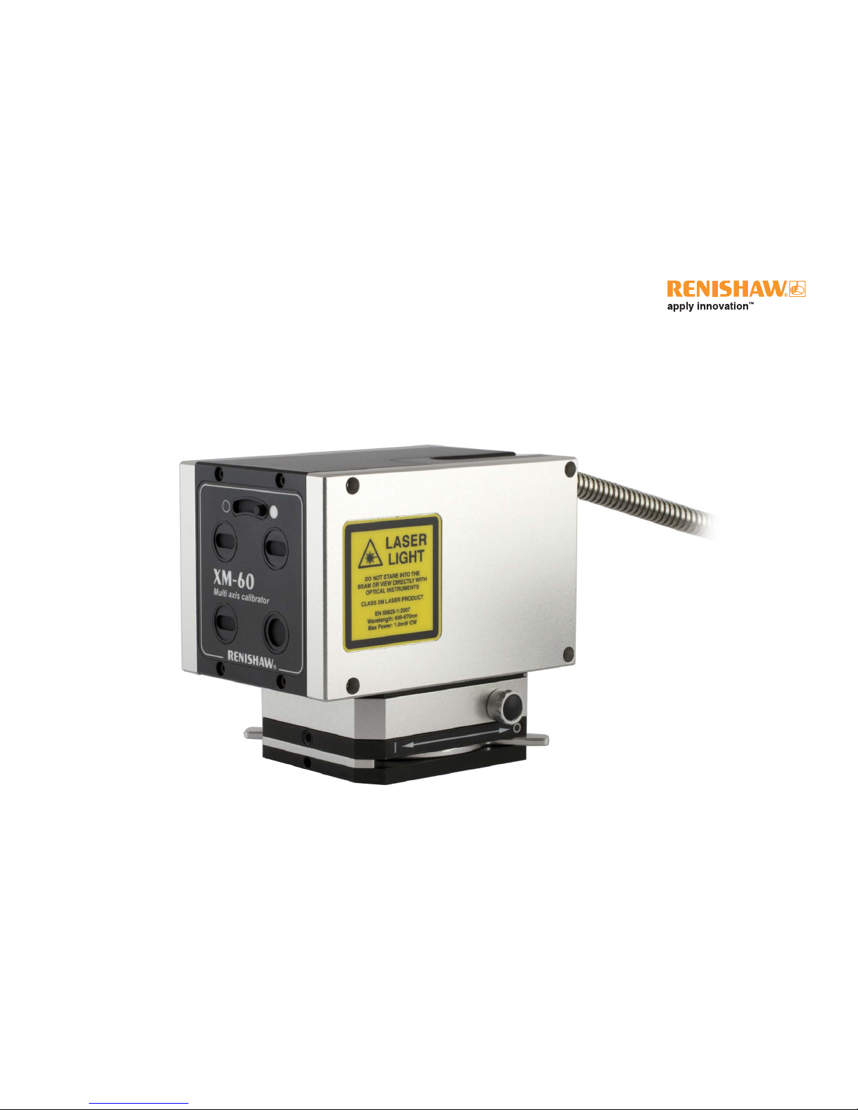
XM multi-axis calibrator
Page 2

XM multi-axis calibrator
Patents
Features of the XM multi-axis calibrator, and other similar Renishaw products, are
subject of one or more of the following patents and/or patent applications:
CN 101715540 US 2016/0169710
CN 105637326 US 5975744
EP 3028011 US 6473250
GB 2337339 US 6597505
IN WO2015/015213 US 7304815
JP 2015/015213 US 8368887
JP 4499924
Renishaw part no: F-9921-0201-04-B
Issued: 09.2018
Legal information
Disclaimer and warranty information
Renishaw reserves the right to make changes to this document and to the product
described herein without obligation to notify any person of such changes.
Disclaimer
Renishaw has made considerable efforts to ensure the content of this document
is correct at the date of publication but makes no warranties or representations
regarding the content. Renishaw excludes liability, howsoever arising, for any
inaccuracies in this document.
Warranty
Equipment requiring attention under warranty must be returned to your equipment
supplier.
Unless otherwise specifically agreed in writing between you and Renishaw, if you
purchased the equipment from a Renishaw company, the warranty provisions
contained in Renishaw’s CONDITIONS OF SALE apply. You should consult these
conditions in order to find out the details of your warranty but, in summary, the
main exclusions from the warranty are if the equipment has been:
• neglected, mishandled or inappropriately used; or
• modified or altered in any way except with the prior written agreement of
Renishaw.
If you purchased the equipment from any other supplier, you should contact them
to find out what repairs are covered by their warranty.
Trade marks
RENISHAW and the probe symbol used in the RENISHAW logo are registered
trade marks of Renishaw plc in the United Kingdom and other countries. apply
innovation and names and designations of other Renishaw products and
technologies are trade marks of Renishaw plc or its subsidiaries.
All other brand names and product names used in this document are trade
names, trade marks, or registered trade marks of their respective owners.
Copyright
© 2016-2018 Renishaw. All rights reserved.
This document may not be copied or reproduced in whole or in part, or transferred
to any other media or language, by any means without the prior written
permission of Renishaw. The publication of material within this document does not
imply freedom from the patent rights of Renishaw plc.
Page 3
XM multi-axis calibrator
Legal information
International regulations and conformance
EC compliance
Renishaw plc declares that the XM system complies with the applicable directives,
standard and regulations. A copy of the full EC Declaration of Conformity is
available upon request.
In compliance with BS EN 61010-1:2010 the product is safe to use in the following
environmental conditions:
• Indoor use only
• Altitude up to 2000 m
• Maximum relative humidity (non-condensing) of 80% for
temperatures up to 31 °C decreasing linearly to
50% relative humidity at 40 °C
• Pollution Degree 2
RoHS compliance
Compliant with EC directive 2011/65/EU (RoHS)
Packaging component Material ISO 11469 Recycling
guidance
Outer box Cardboard N/A Recyclable
Inserts Cardboard N/A Recyclable
Bags Low density polyethylene LDPE Recyclable
WEEE
The use of this symbol on Renishaw products and/or accompanying
documentation indicates that the product should not be mixed
with general household waste upon disposal. Due to fibre optic
handling requirements the unit must be returned to Renishaw for
disposal. Please contact your local Renishaw office to arrange
collection. Correct disposal of this product will help to save valuable
resources and prevent potential negative effects on the environment.
For more information, please contact your local Renishaw office.
Page 4
XM multi-axis calibrator
Radio communication
The wireless communication module used within the XM system is pre-approved
in a number of regions including EU, EFTA countries, USA and Canada.
Module manufacturer: Laird plc
Part number: TRBLU23-00200
FCC ID: FCC ID PI401B
Module ID No: 1931 B-BISMII
For details of national radio approvals for this device, see the Compliance
with radio device regulations document on the Calibration product quality and
conformance web pages.
Further radio approval country specific statements can be found below:
Singapore
Reg. No. N1116-17
Complies with
IDA Standards
DA104642
Mexico
La operación de este equipo está sujeta a las siguientes dos condiciones:
(1) es posible que este equipo o dispositivo no cause interferencia perjudicial y
(2) este equipo o dispositivo debe aceptar cualquier interferencia, incluyendo la
que pueda causar su operación no deseada.
Taiwan
低功率電波輻性電機管理辦法
第十二條經型式認證合格之低功率射頻電機,非經許可,公司、商號或使用者均不
得擅自變更頻率、加大功率或變更原設計之特性及功能。
第十四條低功率射頻電機之使用不得影響飛航安全及干擾合法通信;經發現有干擾
現象時,應立即停用,並改善至無干擾時方得繼續使用。前項合法通信,指依電信
規定作業之無線電信。低功率射頻電機須忍受合法通信或工業、科學及醫療用電波
輻射性電機設備之干擾 。
Page 5

XM multi-axis calibrator
Legal information
USA and Canadian regulations
FCC
Information to the user (47CFR:2001 part 15.19)
This device complies with Part 15 of the FCC rules. Operation is subject to the
following conditions:
This device may not cause harmful interference.
This device must accept any interference received, including interference that may
cause undesired operation.
Information to the user (47CFR:2001 part 15.105)
This equipment has been tested and found to comply with the limits for a Class A
digital device, pursuant to Part 15 of the FCC rules. These limits are designed to
provide reasonable protection against harmful interference when the equipment
is operated in a commercial environment. This equipment generates, uses and
can radiate radio frequency energy and, if not used in accordance with this user
guide, may cause harmful interference to radio communications. Operation of this
equipment in a residential area is likely to cause harmful interference, in which
case you will be required to correct the interference at your own expense.
Information to the user (47CFR:2001 part 15.21)
The user is cautioned that any changes or modifications, not expressly approved
by Renishaw plc or authorised representative, could void the user’s authority to
operate the equipment.
Special accessories (47CFR:2001 part 15.27)
The user is also cautioned that any peripheral device installed with this
equipment, such as a computer, must be connected with a high-quality shielded
cable to ensure compliance with FCC limits.
Canada – Industry Canada (IC)
This device complies with RSS 210 of Industry Canada. Operation is subject to
the following two conditions: (1) this device may not cause interference, and (2)
this device must accept any interference, including interference that may cause
undesired operation of this device.
L’utilisation de ce dispositif est autorisée seulement aux conditions suivantes :
(1) il ne doit pas produire d’interference et (2) l’utilisateur du dispositif doit étre
prêt à accepter toute interference radioélectrique reçu, même si celle-ci est
susceptible de compromettre le fonctionnement du dispositif.
Page 6

XM multi-axis calibrator
Contents
Legal information ........................ 2
Safety information........................ 7
Safety labelling ........................... 8
Mechanical safety ......................... 9
Laser optical safety ........................ 9
Electrical and power safety ................. 10
Battery safety ........................... 10
Fibre optic safety......................... 11
Principles of measurement...............12
XM multi-axis calibrator.................... 12
System components..................... 14
XM-60 system kit ........................ 14
System components..................... 15
XM-600 system kit ....................... 15
Laser / Launch ........................ 16
Receiver ............................. 17
Calibration software kit .................. 18
XC-80 environmental compensator .......... 19
Fixturing kit . . . . . . . . . . . . . . . . . . . . . . . . . . . . . 20
Other accessories for use on CMMs.......... 21
Setting up a test......................... 22
Testing precautions....................... 22
Quick start system set-up using CARTO software 24
Test overview ........................... 25
XM system set-up ........................ 26
XC-80 set-up............................ 28
Basic rules of alignment ................... 29
Alignment overview....................... 30
Visual axis alignment ................... 31
Fine axis alignment .................... 34
Receiver alignment..................... 36
Data capture ............................ 37
Data analysis ........................... 39
Diagnostics and troubleshooting .........40
Laser LED .............................. 40
Receiver LED ........................... 41
Battery charger LED ...................... 42
System troubleshooting ................... 43
Measurement troubleshooting .............. 44
Care and handling .......................45
System ................................ 45
Conduit ................................ 45
Optics ................................. 45
System specifications ...................46
Performance specifications................. 47
Operating and storage environment . . . . . . . . . . 48
Radio communication ..................... 49
PICS connector (XM-600 only) .............. 49
Receiver battery and charger ............... 50
Power supply unit ........................ 51
Weights ................................ 52
Dimensions (laser unit) .................... 52
Dimensions (launch unit) .................. 53
Dimensions (receiver unit) ................. 54
Appendix A .............................55
Replacing the receiver battery .............. 55
Appendix B .............................56
Using the 90 degree bracket................ 56
Appendix C .............................57
Sign detection ........................... 57
Appendix D .............................58
Machine tool fixturing kit good practice guide ... 58
Appendix E .............................63
Example XM system set-ups on CMM ........ 63
Appendix F .............................64
Straightness measurement ................. 64
Angular errors ........................... 65
XM set-up best practice ................... 66
Page 7
7
XM multi-axis calibrator
Safety information
Use of controls or adjustments or performance of
procedures other than those specified herein may result
in hazardous radiation exposure.
Ensure that you read and understand the XM system
user guide before using any XM system.
The XM system can be used in a variety of environments and applications. To
ensure the safety of the user and other personnel in the vicinity it is therefore
paramount that a comprehensive risk assessment is carried out for the machine
under test before using the XM system.
This should be carried out by qualified users (requiring machine competency,
applicable technical knowledge and a trained risk assessor) with consideration for
the safety of all personnel. The risks identified must be mitigated prior to using the
product. The risk assessment should pay particular attention to machine, manual
handling, mechanical, laser, electrical, power and fibre optic safety.
Based on current research, the wireless devices used in this product would not
seem to pose a significant health problem for the vast majority of pacemaker
wearers. However, people with pacemakers may want to ensure a minimum
distance of 3 cm between the XM system and the pacemaker.
Page 8
8
XM multi-axis calibrator
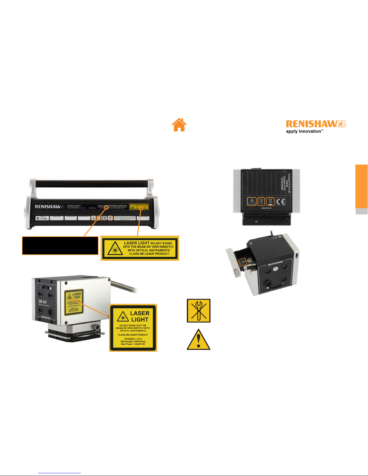
Safety labelling
There are no user-serviceable parts inside the XM system. Do not
remove any part of the housing; to do so could expose the user to
high voltages and/or Class 3R laser radiation.
Ensure that you read and understand the XM system user guide
before using any XM system.
COMPLIES WITH FDA PERFORMANCE STANDARDS FOR
LASER PRODUCTS EXCEPT FOR DEVIATIONS PURSUANT
TO LASER NOTICE NO.50, DATED JUNE 24, 2007
Page 9

9
XM multi-axis calibrator
Mechanical safety
• When setting up and mounting Renishaw XM and XC-80 systems beware
of pinch and/or crush hazards that may be created e.g. due to magnetic
mounting bases.
• Beware of trip hazards that may be created when using the XM and XC-80
systems, e.g. due to trailing cables.
• Exercise caution if components are to be mounted to moving or rotating
machinery. Beware of cables becoming entangled.
• Exercise extreme caution if XM and XC-80 system components are to be
mounted to machinery that may accelerate rapidly or move at high speed,
which could lead to items colliding or being ejected.
• If it is necessary to operate the machine with the guards or any safety
feature removed or disabled, it is the responsibility of the operator to
ensure that alternative safety measures are taken in line with the machine
manufacturer’s operating instructions or relevant codes of practice.
• If you are using a part program or error correction parameters generated by
the Renishaw software, it is the responsibility of the user to validate these
at low feedrate and be prepared to operate the emergency stop button if
necessary.
• The XM system weighs approximately 24 kg in the case (31 kg with the
machine tool fixturing kit attached). Users should exercise caution and follow
local manual handling guidelines.
Laser optical safety
• In accordance with (IEC) EN60825-1, XM systems are Class 2M lasers and
safety goggles are not required (under normal circumstances the eye will
blink and look away before damage can occur).
• Do not stare directly into the laser beams or view them with optical
equipment such as telescopes, convergent mirrors or binoculars as
permanent retinal damage could occur. Do not direct the beam at other
people or into areas where people unconnected with laser work might be
present. It is safe to view a diffuse-reflected beam during system alignment.
• FDA compliance (USA) – complies with 21CFR1040.10 and 1040.11 except
for deviations pursuant to laser notice no. 50, dated 24 June, 2007.
Rotating the shutter to the closed position (the right hand position on the picture)
ensures no beam is emitted.
Page 10
10
XM multi-axis calibrator
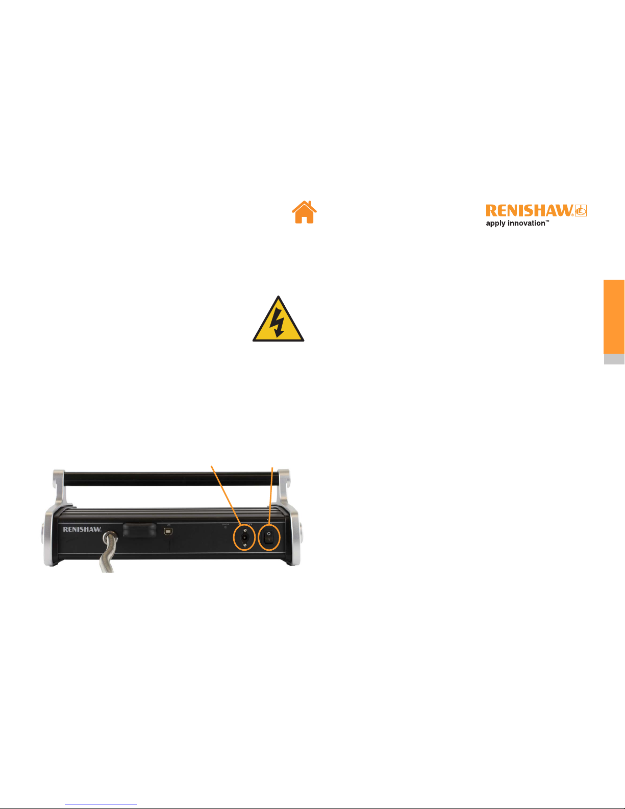
Power connector On/off switch
Electrical and power safety
• The power supply unit must not come into contact with
fluids e.g. coolant on the floor.
• The power supply unit must not be positioned inside the
machine volume.
• The XM system has been qualified for use with the power
supply unit supplied with the system. A specification for this power supply
unit can be found here.
• In the event of damage to the single phase mains cabling section of the
power supply (power lead), all power must be isolated from the equipment
before any other action is taken.
• Never connect the system to devices not intended to be used with the
XM system.
Battery safety
The XM multi-axis calibrator is supplied with rechargeable batteries.
• Once depleted, recharge the battery in the charger provided: do not attempt
to charge the battery by other means.
• For specific battery operating, safety and disposal guidelines, please refer to
the battery manufacturers’ literature.
• Replace the batteries only with the specified type.
• Ensure that all batteries are inserted with the correct polarity.
• Do not store batteries in direct sunlight.
• Do not heat or dispose of batteries in a fire.
• Do not short-circuit or force discharge the batteries.
• Do not disassemble, pierce, deform or apply excessive pressure
to the batteries.
• Do not swallow the batteries.
• Keep the batteries out of the reach of children.
• Do not get batteries wet.
• If a battery is damaged, exercise caution when handling it.
Page 11

11
XM multi-axis calibrator
Battery safety
Transportation
Please ensure that you comply with international and national battery transport
regulations when transporting batteries or XM system kits.
The XM system uses a lithium ion battery. Lithium batteries are classified as
dangerous goods and strict controls apply on their shipment by air. To reduce the
risk of shipment delays, should you need to return the XM system to Renishaw for
any reason, do not return any batteries.
The operation of wireless appliances on aircraft is forbidden by many airlines
to prevent interference with communications systems. Remove the battery from
the receiver unit when boarding an aircraft to ensure it cannot be switched on
inadvertently.
EU REACH SVHC compliance
Please see the relevant battery manufacturer’s website for further information:
Varta: http://www.varta-microbattery.com/en/news-downloads/downloads.html
Fibre optic safety
The XM system contains fibre optics. In the unlikely event that the flexible steel
conduit is cut or severed, fibre optic splinters may be produced.
Fibre optic splinters can be very small and extremely sharp. Should any fibre
optic splinter become embedded in the skin, medical attention should be sought
immediately.
Should the fibre optic become damaged, the following procedure should be
followed (be aware that the affected area might contain splinters of unattached
fibre optic which can present a hazard):
• immediately power down the XM system,
• wear eye protection and protective gloves when handling damaged or
exposed fibre optics,
• carefully remove the XM system from the machine and package in a suitable
thick-walled cardboard box, clearly marked ‘Caution: exposed fibre optics,
handle with care’ on the outside of the box,
• return the unit to the nearest Renishaw office.
No attempt should be made to repair or dismantle the fibres from the laser unit.
Note: Fibre optic splinters do not show up on X-rays.
The use of this symbol on the batteries, packaging or accompanying documents
indicates that used batteries should not be mixed with general
household waste. Please dispose of the used batteries at a
designated collection point. This will prevent potential negative effects
on the environment and human health which could otherwise arise
from inappropriate waste handling. Please contact your local authority
or waste disposal service concerning the separate collection and
disposal of batteries. All lithium and rechargeable batteries must be
fully discharged or protected from short circuiting prior to disposal.
Page 12
12
XM multi-axis calibrator
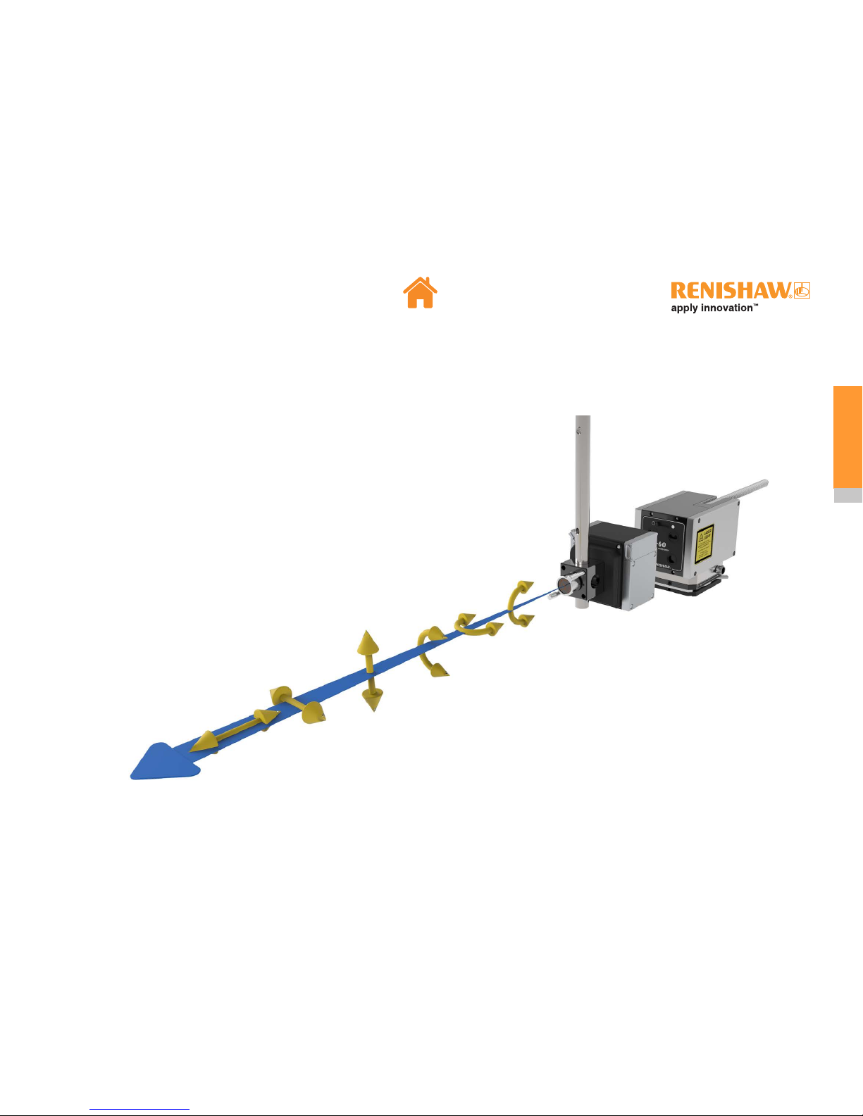
XM multi-axis calibrator is a laser measurement system capable of measuring six degrees of freedom:
• along a linear axis
• in any orientation
• from a single set-up
The measured errors are:
• Linear positioning of the axis
• Angular rotation in the vertical plane (pitch)
• Angular rotation in the horizontal plane (yaw)
• Straightness deviation in the vertical plane
• Straightness deviation in the horizontal plane
• Roll about the linear axis of travel
Principles of measurement
XM multi-axis calibrator
Page 13

13
XM multi-axis calibrator
The XM system uses three laser beams (1,2 and 3) to measure the linear, pitch
and yaw errors using interferometry. The light emitting diode (LED) beam (4) is
used for straightness and roll measurements.
The basic measurement concept is:
Angular
The three interferometric beams provide a linear measurement
of the separation between launch and receiver. Because the
distance between these beams is known, angular errors of pitch
and yaw can be determined by the system.
Linear
Using the pitch and yaw measurements, the linear error is
determined based on the combination of beams 1, 2 and 3 to
calculate the linear error at the position of beam 4.
The 4th (diode source) beam is used to measure straightness and roll.
Straightness
The vertical and horizontal straightness error is measured using
a position sensor within the receiver and transmitted back to the
laser via wireless communication.
Roll
Roll measurement is performed optically using a roll detector
inside the receiver. Roll measurements are absolute between
the launch and the receiver.
1
2
3
4
Page 14
14
XM multi-axis calibrator
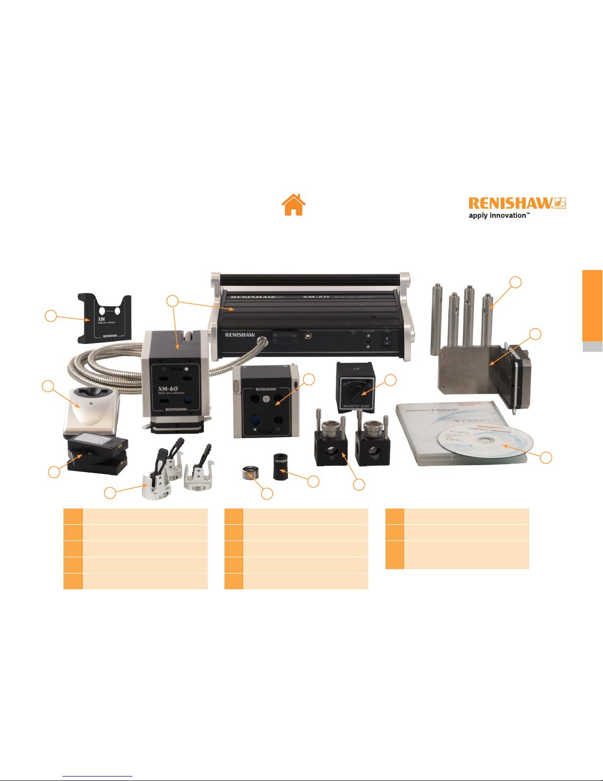
1
Laser / Launch
2
Receiver
3
Calibration software kit
4
Beam shroud
5
90 degree bracket
6
Battery Li-Polymer 3.7 V × 3
7
Battery charger
8
Magnetic base
9
Clamp blocks × 2
10
M8 pillars × 4
11
Spirit level
12
Cable clamps × 3
13
Beam blocker (for rotary
applications, see XR20-W rotary
axis calibrator manual for details)
3
4
9
8
2
5
10
11
6
12
7
1
System components
XM-60 system kit
13
Page 15

15
XM multi-axis calibrator
1
Laser / Launch
2
Receiver
3
Calibration software kit
4
Beam shroud
5
90 degree bracket
6
Battery Li-Polymer 3.7 V × 3
7
Battery charger
8
Magnetic base
9
Clamp blocks × 2
10
M8 pillars × 4
11
Spirit level
12
Cable clamps × 3
13
PICS cable
14
Beam blocker (for rotary applications,
see XR20-W rotary axis calibrator
manual for details)
3
4
9
8
2
5
13
10
11
6
12
7
1
System components
XM-600 system kit
14
Page 16
16
XM multi-axis calibrator
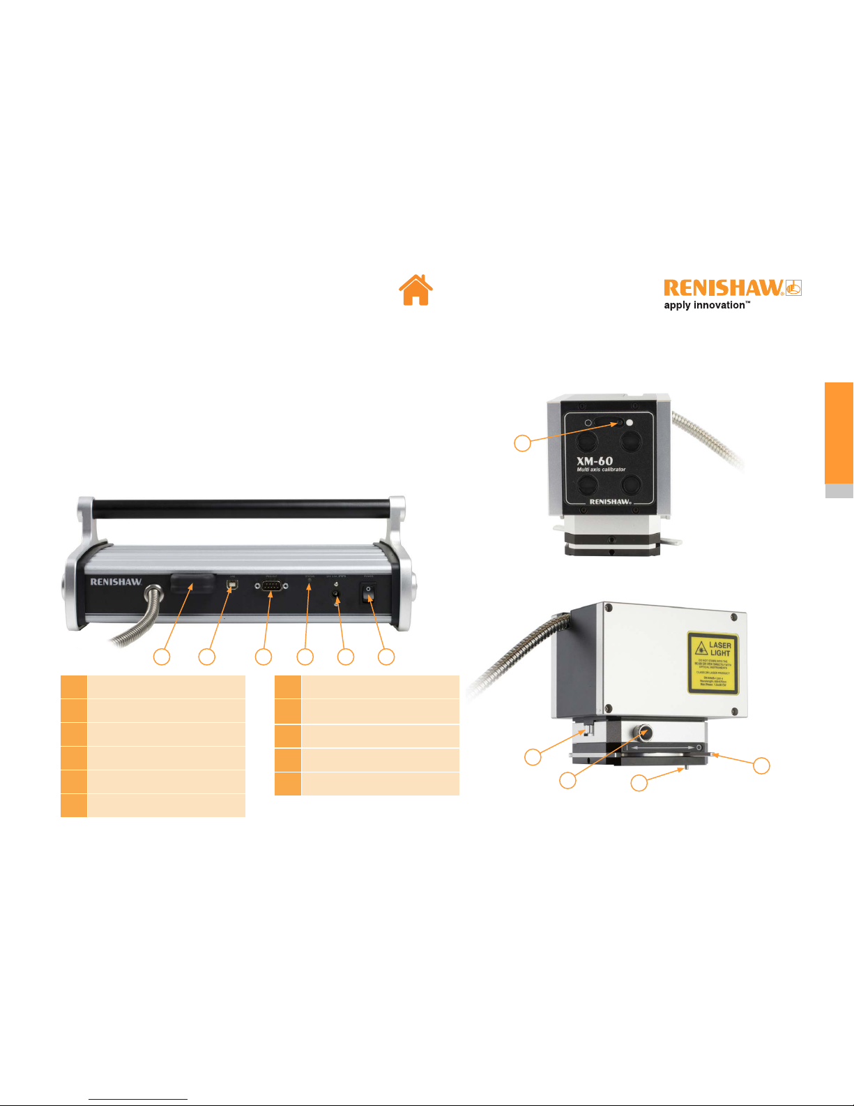
Laser / Launch
The laser contains a Helium-Neon (HeNe) laser tube providing laser beams
to the launch via fibre optics. In addition, the laser contains signal processing
electronics.
The laser beam is split into three in the launch for linear and angular
measurements. It also houses a diode beam source for roll and straightness
measurements.
1
Wireless communication module
2
USB connection port
3
PICS connector (XM-600 only)
4
System status LED
5
Power connector
6
Power on/off switch
7
Laser safety shutter
8
Magnetic mount safety pin
(prevents accidental magnet operation)
9
Magnetic clamp on/off lever
10
Pitch adjuster
11
Yaw adjuster
8
9
10
7
11
1
2
6
4 53
Page 17
17
XM multi-axis calibrator
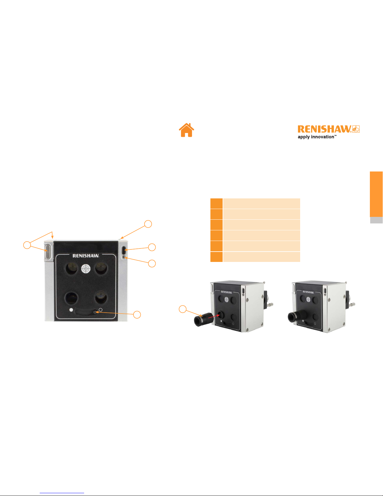
Receiver
The receiver contains three retro-reflectors for the interferometric laser beams.
It also contains a straightness and roll sensor for the diode beam, data from this
sensor is transmitted to the laser via wireless communication.
The beam shroud is attached by a ‘push-fit’ on to the receiver roll aperture.
1
Beam shroud
2
Roll adjuster
3
Shutter
4
Battery release buttons
5
Power button
6
Receiver/battery status LED
5
2
6
3
1
4
Page 18
18
XM multi-axis calibrator
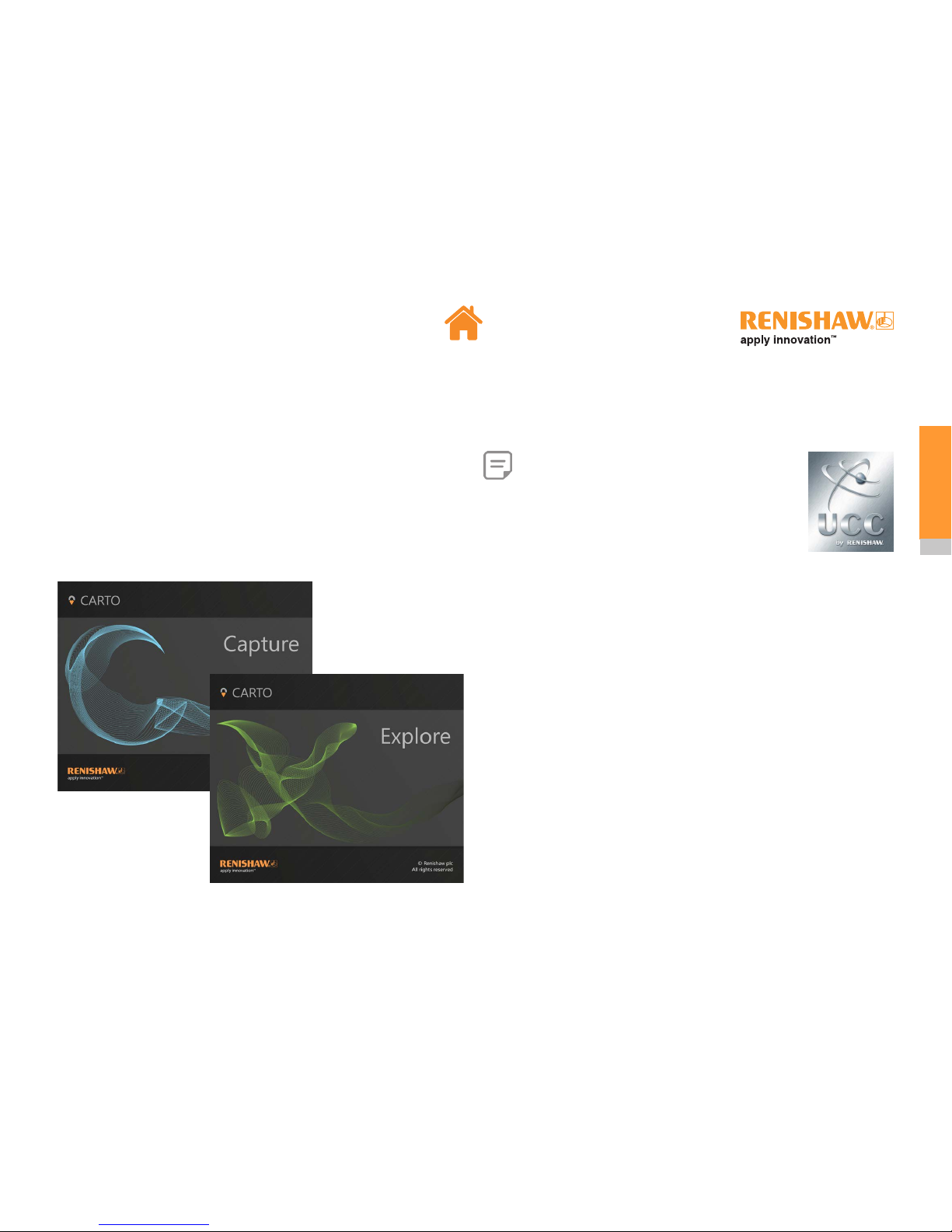
Calibration software kit
The XM system is supplied with the “Calibration software kit” which comprises:
• CARTO suite
• User guides and documentation for XM, XL-80, XC-80 and XR20-W
The CARTO suite features two applications:
Note: XM-600 supports additional functionality when
used on a CMM which is equipped with Renishaw’s
UCC system. This functionality is accessed using UCC
Assist, which is part of UCC Suite - a software package for the
CMM controller. XM-600 is supported from UCC Suite V5.4.
UCC Assist enables additional features which are unique to
XM-600, and contains support information on how to use XM600 to calibrate a UCC-equipped CMM.
Page 19
19
XM multi-axis calibrator
XC-80 environmental compensator
The XM specified accuracy for interferometric measurements is only valid when
used with a calibrated XC-80 environmental compensator.
Changes in air temperature, pressure and relative humidity affect the wavelength
of the laser light and, therefore, the measurement readings taken.
The XC-80 environmental compensator and its sensors very accurately measure
the environmental conditions and compensate the wavelength of the laser beam
for variations in air temperature, air pressure and relative humidity.
Note: For full details on XC-80 operation and specification please refer to
XC-80 user guide.
Page 20
20
XM multi-axis calibrator
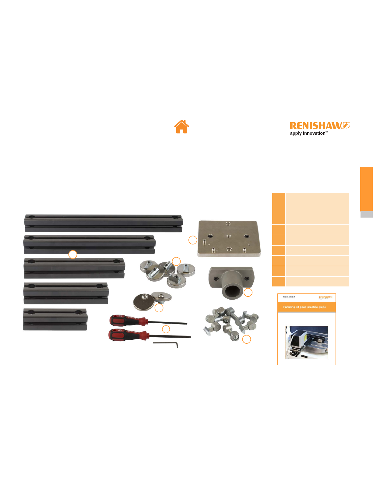
Fixturing kit
An optional fixturing kit is available. It provides the user with more flexible mounting options, particularly when a magnetic surface is available.
Typical applications of the fixturing kit include:
• Overhang the XM launch unit to enable the full travel of an axis to be measured
• Secure the launch unit in the chuck of a lathe or mill-turn machine tool (See Appendix D)
1
450 mm extrusion
350 mm extrusion
250 mm extrusion
200 mm extrusion
150 mm extrusion
2
Extrusion connectors × 8
3
Magnets × 5
4
Extrusion alignment aids × 2
5
Lathe adaptor
6
Steel mounting plate
7
Hex drivers × 3
7
1
2
3
4
5
6
Page 21
21
XM multi-axis calibrator
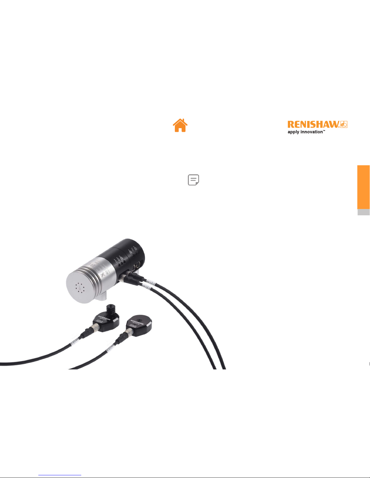
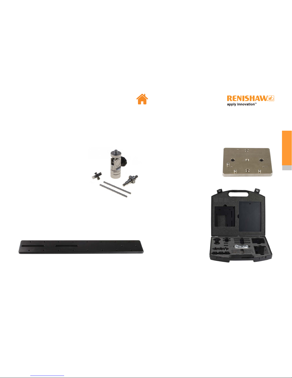
Other accessories for use on CMMs
Additional accessories are available to allow flexible use of the XM system (see Appendix E). These can be used to:
Pan / Tilt Adaptor
• Elevate the launch unit. This may be
useful when the machine has otherwise
insufficient axis travel to move receiver
to required position.
• Use the XM system when there are no
convenient mounting surfaces that are
parallel or perpendicular to the direction
of machine travel.
• Rapidly change launch unit orientation
between horizontal and vertical.
CMM table plate adaptor
• Provide a base on which to support the launch unit when a convenient
magnetic surface is not available on the machine (compatible with threaded
hardware up to M12).
• Overhang the XM launch unit to enable the full travel of an axis to be
measured.
Steel mounting plate
• Provide a repeatable, magnetic
mounting point for the XM launch unit
and the 90° bracket, such as on the
length bar plate, pan/tilt adaptor or
customer-designed fixturing.
Machine optics mounting kit
• Use the XM system where a
magnetic mounting location for
the receiver is not convenient.
• Assemble lightweight mounting
solutions for the XM receiver.
• Quickly and conveniently mount
the XM receiver onto the quill of
a CMM in place of a Renishaw
head.
Page 22

22
XM multi-axis calibrator
Setting up a test
Testing precautions
Light interference
External light can cause errors in roll measurement performance.
To minimise the effect of light interference the user should:
• Always use the beam shroud
• Switch off the machine lighting
• Minimise external lighting
Sources of lighting that can affect the performance are:
• Sunlight
• Flashing beacons
• Welding
• LED and fluorescent room lighting
Performance can be affected by abnormal changes in any of the above. It is
important to consider light effect and reflections over the full range of the axis
under test.
CARTO allows the user to perform an ambient light check. See Capture user
guide for details.
Page 23

23
XM multi-axis calibrator
Testing precautions
Thermal stabilisation
• To meet the quoted specifications the XM system must be thermally stable.
• Thermal stability is achieved 45 minutes after the laser/launch and receiver
are powered on. Therefore it is recommended to turn the laser/launch and
receiver on at the earliest opportunity.
• The receiver and the launch must be removed from the case during the
thermal stabilisation period and should be placed at least 200 mm away from
each other.
• To avoid the need for further thermal stabilisation, once discharged the
receiver battery should be changed within 30 seconds:
Mechanical set-up
• In order to take relative measurements between the tool and the workpiece,
the launch must always be attached to the structure that holds the
workpiece, i.e. the machine bed or the chuck on a lathe. See Appendix F for
XM set-up best practice.
• When the XM system is used on a
machine where the workpiece moves,
the conduit should be fixed to the
machine bed to stop it dragging,
misaligning, or causing the launch
to move during machine motion.
Magnetic cable clamps are included
in the kit for this purpose.
• There may be situations when sufficient magnetic force is not available to
securely mount the launch unit. This could occur when there is a requirement
for overhanging the launch unit, or the machine bed is not magnetic. In this
case, additional fixturing components (such as the Machine Tool Fixturing Kit
or other mounting accessories) may be required.
• In general, metrology performance is improved when the system is
used with fewer accessories. Use only the minimum amount of fixturing
components required to align the system to the axis under test.
Note: An uninterruptible power supply can be used when moving
XM from one machine to the next.
30
seconds
Page 24

24
XM multi-axis calibrator
Quick start system set-up using CARTO software
Application XM-60 XM-600
CNC machine tool / lathe CARTO software CARTO software
UCC-equipped CMM CARTO software UCC Assist software
Non-UCC-equipped CMM CARTO software Contact your local Renishaw office
Together with Renishaw’s CARTO software suite,
the XM systems can be used to calibrate most
CNC machines.
With XM-600, additional features are available
on some machines (such as a CMM with a UCC
controller), and other software may offer greater
functionality.
Page 25

25
XM multi-axis calibrator
Receiver alignment
Test overview
The steps to perform a test using the XM system are as follows (click on links to jump to relevant section):
Set-upAlignmentCapture
XC-80 set-up
Fine axis alignment
XM set-up
Visual axis alignment
Data analysis
Data capture
Page 26

26
XM multi-axis calibrator
XM system set-up
The recommended set-up sequence for the XM system is as follows:
Attach the beam shroud to the receiver roll aperture
Fit the battery in the receiver
Switch the laser on
Connect the power supply to the laser
Ensure the launch shutter is closed
Take the removable tray out of the case before removing launch
Page 27

27
XM multi-axis calibrator
XM system set-up
Connect the XM laser to the PC
Mount the receiver to the part of the machine where
the tool would be attached
Where appropriate, level the launch using the spirit level
Attach the launch to the bed of the machine,
parallel to the axis under test
Turn the receiver on
0.5
seconds
Page 28

28
XM multi-axis calibrator
XC-80 set-up
The recommended set-up sequence for the XC-80 is as follows:
Connect the XC-80 to the PC
Position the air temperature sensor on the machine
Attach the XC-80 environmental compensator to the
machine
Connect the air and material sensors to the XC-80
Note: For more information on sensor positioning refer to XC-80 user guide
Page 29

29
XM multi-axis calibrator
Basic rules of alignment
1. Launch and receiver are close to each other = translation adjustment
2. Launch and receiver are far from each other = rotation adjustment
Page 30

30
XM multi-axis calibrator
Alignment overview
The recommended alignment sequence is as follows (click on links to jump to relevant section):
Receiver alignment
Fine axis alignment
Visual axis alignment
Page 31

31
XM multi-axis calibrator
Visual axis alignment
Visual axis alignment is performed using the target on the front of the receiver.
Translate the machine so that one of the beams is on the
receiver target
Open the shutter on the launch and the receiver
Visually check the launch and the receiver are parallel to
each other
Move the launch and the receiver as close to each other
as possible
Set the pitch and yaw adjusters to the middle of their travel
Pitch
Yaw
Page 32

32
XM multi-axis calibrator
Visual axis alignment
Continue the process below until the beam stays on the target during the full machine movement. Use the machine to perform translations and pitch/yaw adjusters for
rotational alignment.
Page 33

33
XM multi-axis calibrator
Translate
Move the machine to align the laser beams into the
receiver apertures. Adjust position until the straightness
beam appears in CARTO
Select Align
Select New or Open
Run Capture
Page 34

34
XM multi-axis calibrator
Fine axis alignment
Continue the process below until the beam stays on the target in CARTO software during the machine movement.
Page 35

35
XM multi-axis calibrator
Fine axis alignment
Roll alignment
Adjust the roll lever to the centre of the roll display.
Page 36

36
XM multi-axis calibrator
Receiver alignment
• To maintain the system accuracy the launch and the receiver must be
parallel to each other.
• The software will check the parallelism on the completion of the fine axis
alignment.
• If the parallelism tolerance is not met when selecting Capture, the software
will prompt the user to physically adjust the mounting of the receiver. Rotate
the receiver until the red border disappears. Do not adjust the pitch and yaw
adjustment of the launch unit.
Note: It maybe necessary to perform minor translation of the
machine after this step is complete.
Note: Once set-up is complete and before capturing data, it is
recommended to perform an ambient light check. See Capture user
guide for details.
Page 37

37
XM multi-axis calibrator
Note: For full details on Capture please refer to the Capture user guide.
1
Define
2
Bring close
3
Capture
4
Datum
5
Move to start position
6
Start
300.00mm
Data capture
Page 38

38
XM multi-axis calibrator
Data capture
Roll tuning
When Start is selected the system will perform a calibration cycle on the roll
detection scheme to compensate for the set-up conditions.
Sign detection
To ensure the errors of the machine are measured with the correct sign (+/-) it
is important that the coordinate system of the XM (X,Y,Z and their directions) is
labelled according to that of the machine. Further details on sign detection can be
found here.
There are two methods of sign detection:
• Automatic
Part programs produced with CARTO will perform machine moves to detect
the sign.
• Manual
The user can manually jog the machine ±150 µm in each axis when
prompted by the software to perform sign detection.
Note: Users can skip an axis if they don’t have three perpendicular
axes. Further details can be found in the Capture user guide.
On completion of these steps the system will start capturing data.
Page 39

39
XM multi-axis calibrator
Data analysis
On completion of the test select Analyse to launch Explore.
Note: For further details on Explore please refer to the Explore user guide.
Page 40

40
XM multi-axis calibrator
This LED demonstrates the laser status and the wireless communication with the receiver.
LED status Description Actions
Flashing amber Pre-heat cycle No action required
Solid green
• Laser is stabilised
• Receiver is not switched on or the wireless
communication is not yet established
Check the receiver is powered on
Solid blue
• Wireless communication is established
• Software is not running (not synced)
Open Capture in XM mode
Flashing blue
• System operational
• The software is running and the data is being
transmitted from the receiver
No action required
Solid amber Laser unstable
• Check launch/receiver alignment
• If issue persists, power cycle
• If issue persists, contact local Renishaw office
Flashing or solid red Error encountered
• Check all four beams are present
• Power cycle the laser
• If issue persists, contact local Renishaw office
Diagnostics and troubleshooting
Laser LED
Page 41

41
XM multi-axis calibrator
Receiver LED
After the receiver power button has been pressed, the receiver LED will go through a start-up sequence
and after a few seconds will settle on one of the following options:
LED status Description Actions
Flashing amber No roll beam detected
• Open launch/receiver shutters
• Check launch/receiver alignment
• If issue persists, contact local Renishaw office
Flashing purple
Launch/receiver not synchronised
and/or no roll beam detected
Run Capture while making sure launch/receiver shutters are open
Flashing blue System is operational No action required
Periodic one second amber
followed by usual operational
sequence
Low battery Replace the battery (See Appendix A)
None
• Battery charge too low
• Battery contacts dirty/damaged
• Battery inserted incorrectly
• Receiver not operational
• Insert a fully charged battery
• If issue persists, contact local Renishaw office
Flashing green
Wireless communication device is
not operational
• Power cycle the receiver
• If issue persists, contact local Renishaw office
Flashing or solid red Receiver not operational
• Power cycle the receiver
• If issue persists, contact local Renishaw office
Page 42

42
XM multi-axis calibrator
Battery charger LED
LED status Description
Solid amber Fast charge in progress
Flashing amber Pre-charge in progress
Solid green Power on and no battery connected, or battery full
Flashing red Failure
Page 43

43
XM multi-axis calibrator
System troubleshooting
Problem Action
Software is not installed in my language • Check PC system locale is set correctly
XM is not recognised by CARTO
• Ensure Capture is running in the XM system mode
• Check the XM is connected to the PC USB port
• Try a different USB port on the PC (the port could be damaged)
• Disconnect USBs, power cycle XM/PC, reconnect USBs
• If issue persists, contact local Renishaw office
Cannot align my XM
• Ensure shutters on launch/receiver are open
• Check four beams are present from launch using a card as a target.
If not present, power cycle XM.
• Restart XM alignment
• If issue persists, contact local Renishaw office
CARTO diagnostic messages • Please refer to Capture user guide
Page 44

44
XM multi-axis calibrator
Measurement troubleshooting
Problem Possible causes Action
Beam strength fluctuating Environment is outside operating temperature range Ensure XM environment is between 10 °C - 40 °C
Beam strength fluctuating during
machine movement
• Normal behaviour at increased speed between
targets
• Receiver clamp block is not tight
• No action required (this has no effect on metrology)
• Tighten the receiver clamp block
All data looks noisy XM fixed loosely Improve the rigidity of the system mounting
All data (except for roll) looks
noisy
The unit is positioned in turbulent air environment Reposition the unit to avoid the turbulent air or stir the air with a fan
Noisy straightness measurement None or short term averaging is used Select long term averaging in Capture
Drift (most significant for linear
measurements)
The system and/or the set-up is not thermally
stabilised
• Perform a number of runs before capturing data for the machine axis
to thermally stabilise
• Ensure the laser/receiver are warmed up as per recommendations
before testing. Specifications - warm up time.
• If the receiver battery has been replaced, follow the thermal
stabilisation recommendations.
• Avoid excessive handling of the launch/receiver to avoid body heat
exchange
• If using custom mounting parts, ensure they are suitable to avoid
thermal growth
Page 45

45
XM multi-axis calibrator
Care and handling
System
• It is recommended to store the XM in the system case when not in use.
• Do not attempt to clean the system with water or other fluids.
• Avoid exposure to oil and coolant.
• Do not direct the air lines at the XM.
• Do not expose the system to impact.
Conduit
• Ensure the conduit is not pinched, crushed or stretched. If damaged, consult
the Fibre optic safety section.
• When storing in the case, twist the launch whilst vertical to allow the conduit
to coil.
• If the laser is left in the case during measurement, do not close the lid of the
case to avoid damage to the conduit.
• Fix the conduit using the magnetic cable clamps to ensure the conduit does
not drag, misaligning the launch.
− Manually check the movement of the axis over the full range of the test,
before running a test.
• Never hold the laser or launch by the conduit.
Optics
Cleaning of the optics should be a last resort
To maintain system performance, the XM optics must be kept clean by
following good handling practice:
• Close the receiver and launch shutters when not in use.
• Do not touch the optical surfaces.
• Minimise use in contaminated atmospheres.
Cleaning recommendations
• Only use approved solvents for cleaning the optics: Methylated spirit and
optical grade IPA only (methylated spirit is preferred to IPA).
• Wipe only with non-abrasive lens tissue or lint-free cloth wrapped around a
cotton bud (do not use a cotton bud directly on the optic as this may increase
debris).
• Clean the optics using a gentle action. Never use a scrubbing action as this
might damage the coatings.
Failure to follow these recommendations may lead to damage to the coatings and
glass elements of the optics.
Page 46

46
XM multi-axis calibrator
System specifications
XM system
Beam source HeNe laser and light emitting diode (LED) (Class 2M)
Beam power (maximum output) < 1 mW (sum of four beams)
Mode of operation
Continuous-wave (HeNe)
Pulsed (LED)
Nominal laser beam diameter 3 mm
Source wavelengths 633 nm and 655 nm nominal
Recommended recalibration period 2 years under typical use
Warm up time (measured from receiver and laser power on)
45 minutes
• 15 minutes laser tube pre-heat
• 30 minutes thermal drift reduction
Input power connector
Inner core = 24 V
Outer core = 0 V
Maximum velocity 1 m/s
Page 47

47
XM multi-axis calibrator
Performance specifications
Linear
Accuracy ±0.5 ppm (with environmental compensation)
Resolution 1 nm
Range 0 m to 4 m
Angular (pitch/yaw)
Accuracy
±0.006A ±(0.5 µrad +0.1M µrad)
(M = measured distance in metres) (A = displayed angular reading)
Resolution 0.03 µrad
Range ±500 µrad
Straightness
Accuracy ±0.01A ±2 µm (A = displayed straightness reading)
Resolution 0.25 µm
Range 250 µm radius
Roll
Accuracy ±0.01A ±9.1 µrad (A = displayed angular reading)
Resolution 0.5 µrad
Range ±500 µrad
Accuracy values are reported to a statistical confidence of 95% (k=2), they do not include the errors associated with the normalisation of the readings to a
material temperature of 20 °C.
Page 48

48
XM multi-axis calibrator
Operating and storage environment
Operating environment
Pressure 600 mbar – 1150 mbar Normal atmospheric
Humidity 0% to 95% RH Non-condensing
Temperature 10 °C to 40 °C
Storage environment
Pressure 550 mbar – 1200 mbar Normal atmospheric
Humidity 0% to 95% RH Non-condensing
Temperature -20 °C to 70 °C
Page 49

49
XM multi-axis calibrator
Radio communication
Class 1 wireless communication device
Output power 0 dBm nominal; +6 dBm maximum
Frequency band 2.402 GHz – 2.480 GHz
Communication distance 12 m typical operation
PICS connector (XM-600 only)
The XM-600 includes a synchronisation output which is designed to be compatible with the PICS interface of Renishaw’s UCC range of CMM controllers. The PICS
signal from the XM-600 is a protected, isolated, open – collector output. The connector on the launch unit is a male 9-way D-Subminiature plug.
The connections on this plug are as follows:
PIN number Function
5 Collector
9 Emitter
All others No Connection
9-way male D-Subminiature plug, viewed from connector side Illustration of internal connection of PICS output
Page 50

50
XM multi-axis calibrator
Receiver battery and charger
Technical data
Battery type Varta EasyPack XL Part # 56456 702 099 (rechargeable Li-Polymer), 3.7 V 2400 mAh 8.9 Wh
Max current 3.7V DC
Battery life 3 hours typical operation (for new batteries)
Technical data
Input voltage 100 V to 240 V AC, 50 Hz / 60 Hz Output Voltage 4.2 V nominal
Input current Max. 0.2 A (100 V AC)
Output current 0 A – 1.0 A
Output power rating Max. 6 W
Safety standard EN(IEC)60950
PC minimum requirements
For details on PC minimum requirements please refer to renishaw.com/lasercalsoftware
Page 51

51
XM multi-axis calibrator
Power supply unit
Technical data
Input voltage 100 V – 240 V
Input frequency 50 Hz – 60 Hz
Maximum input current 1.5 A
Output voltage 24 V
Maximum output current 3 A
Safety standard EN(IEC)60950
Page 52

52
XM multi-axis calibrator
Weights
Weights (approximately)
XM system 6.2 kg (complete system in the case excluding optional XC-80 compensator: 23 kg)
Laser 3.7 kg
Launch 1.9 kg
Receiver 0.6 kg
320
193
Conduit length nominal 3 m
185
122
78
Dimensions (laser unit)
Page 53

53
XM multi-axis calibrator
Dimensions (launch unit)
125.5
123
86
79
114.4
Conduit length
nominal 3 m
124.1
45.1
26.2
25.2
97.5
86
155.2
Page 54

54
XM multi-axis calibrator
16.5
65
82
57.9
8.2
85.15
55
28.1
17.5
11.862.5
86
76
Dimensions (receiver unit)
Page 55

55
XM multi-axis calibrator
Appendix A
Replacing the receiver battery
To replace the battery, follow the procedure below:
2
4
1
3
Page 56

56
XM multi-axis calibrator
Appendix B
Using the 90 degree bracket
The 90 degree bracket can be used in two orientations (standard and reverse).
Reverse orientation allows the launch to be mounted from the side of the machine
tool bed to maximise the length of the axis that can be measured.
When using the 90 degree bracket the user must clock the side face of the
bracket to ensure it is parallel to the axis of travel (e.g. if measuring Z on a vertical
machining centre, clock one of the faces of the 90 degree bracket to the X or Y
axis of the machine).
Standard orientation Reverse orientation Clocking the side face of the bracket
Page 57

57
XM multi-axis calibrator
Appendix C
Sign detection
XM system has 6 measurement channels:
• 3 channels (T1,T2 and T3) correspond to translations (linear and
straightness)
• 3 channels (R1, R2 and R3) correspond to rotations around T1,T2 and T3
Sign detection process performs the following:
• Links the T1,T2 and T3 axes of the XM to the machine linear axes
• Sets the sign (+/-) of the T1,T2 and T3 measurements
• Sets the sign (+/-) of the R1,R2 and R3 measurements
Yaw
Roll
Pitch
Page 58

58
XM multi-axis calibrator
× 2
× 1
A
min
=
B
-----------
5
(if used
with XM)
A
min
=
B
-----------
2
(if used
with XL-80)
A B
Appendix D
Machine tool fixturing kit good practice guide
Page 59

59
XM multi-axis calibrator
3
2
4
1
Page 60

60
XM multi-axis calibrator
5
6
Page 61

61
XM multi-axis calibrator
Page 62

62
XM multi-axis calibrator
Page 63

63
XM multi-axis calibrator
Appendix E
Example XM system set-ups on CMM
Page 64

64
XM multi-axis calibrator
Appendix F
Straightness measurement
Consider a tool machining a component on a machine bed. As the bed moves
from right-left, errors in the machine cause the height of the tool to vary above
the bed.
To measure this effect we measure the height between the tool and the bed
at ‘intervals’ along the movement of the axis. The error is the variation from a
straight line.
Error
Placing the launch unit on the bed of a machine the laser beam becomes the
reference. Variations in height are detected by the receiver as the machine moves
left-right.
Page 65

65
XM multi-axis calibrator
Angular errors
Angular errors (rotations while moving) will cause a variation in
the height difference between the tool and machine bed. This
height variation is also seen on the XM system measurement.
The measurement is not influenced by the exact position of the launch unit ... … but it is affected by the position of the receiver.
The receiver should be positioned as close as possible to the
centre line of the spindle.
Page 66

66
XM multi-axis calibrator
For relative measurements between the tool and the bed/component, the launch
unit must always be mounted on the bed of the machine.
The receiver must always be mounted on centreline of the spindle.
Measurement comparisons
Measurements taken with the launch unit on the bed of
the machine are equivalent to running a dial indicator
along a ‘straight edge’ mounted to the surface of the bed.
XM set-up best practice
If the launch unit is mounted
in the spindle, angular errors
can cause errors in the
straightness measurement.
At the point measured
below there is zero height
variation between tool and
bed, but the XM system
would show a deviation
because of the rotation of
the bed.
Page 67

Renishaw plc
New Mills, Wotton-under-Edge
Gloucestershire, GL12 8JR
United Kingdom
T +44 (0)1453 524524
F +44 (0)1453 524901
E uk@renishaw.com
www.renishaw.com
For worldwide contact details, visit
www.renishaw.com/contact
F-9921-0201-04
© 2016-2018 Renishaw plc
Issued: 09.2018
Part no. F-9921-0201-04-B
 Loading...