

Page 1
UCC T3 PLUS and UCC S3 CMM controller installation guide
Documentation part number: H-1000-2118-01-B
UCC T3 PLUS and UCC S3 CMM controller installation guide
http://www.renishaw.com
Issued 04 2014
1
Page 2

General information
©2014Renishawplc.Allrightsreserved.
This document may not be copied or reproduced in whole or in part, or transferred to any other media or language, by any means, without
the prior written permission of Renishaw.
The publication of material within this document does not imply freedom from the patent rights of Renishaw plc.
Disclaimer
RENISHAW HAS MADE CONSIDERABLE EFFORTS TO ENSURE THE CONTENT OF THIS DOCUMENT IS CORRECT AT THE DATE
OF PUBLICATION BUT MAKES NO WARRANTIES OR REPRESENTATIONS REGARDING THE CONTENT. RENISHAW EXCLUDES
LIABILITY, HOWSOEVER ARISING, FOR ANY INACCURACIES IN THIS DOCUMENT.
Trademarks
RENISHAW® and the probe emblem used in the RENISHAW logo are registered trademarks of Renishaw plc in the UK and other
countries.
apply innovation is a trademark of Renishaw plc.
All brand names and product names used in this document are trade names, service marks, trademarks, or registered trademarks of their
respective owners.
Windows XP, Windows 2000, Vista and Windows 7 are registered trade names of the Microsoft Corporation.
All trademarks and trade names are acknowledged.
WEEE
The use of this symbol on Renishaw products and/or accompanying documentation indicates that the product should not be mixed with the
general household waste upon disposal. It is the responsibility of the end user to dispose of this product at a designated collection point for
waste electrical and electronic equipment (WEEE) to enable reuse or recycling. Correct disposal of this product will help save valuable
resources and prevent potential negative effects on the environment. For more information, please contact your local waste disposal service
or Renishaw distributor.
Warranty
Renishaw plc warrants its equipment for a limited period (as set out in our Standard Terms and Conditions of Sale) provided that it is
installed exactly as defined in associated Renishaw documentation.
Prior consent must be obtained from Renishaw if non-Renishaw equipment (e.g. interfaces and/or cabling) is to be used or substituted.
Failure to comply with this will invalidate the Renishaw warranty.
Claims under warranty must be made from authorised service centres only, which may be advised by the supplier or distributor.
UCC T3 PLUS and UCC S3 CMM controller installation guide
http://www.renishaw.com
Issued 04 2014
2
Page 3

Care of equipment
Renishaw probes and associated systems are precision tools used for obtaining precise measurements and must therefore be treated with
care.
Changes to Renishaw products
Renishaw reserves the right to improve, change or modify its hardware or software without incurring any obligations to make changes to
Renishaw equipment previously sold.
UCC T3 PLUS and UCC S3 CMM controller installation guide
http://www.renishaw.com
Issued 04 2014
3
Page 4

EC declaration of conformity
Renishaw plc hereby declares that the UCC T3 PLUS / UCC S3 is in compliance with the essential requirements and other relevant
provisions of Directives 2004/108/EC. Contact Renishaw plc if a copy is required.
UCC T3 PLUS and UCC S3 CMM controller installation guide
http://www.renishaw.com
Issued 04 2014
4
Page 5

FCC (USA only)
Information to user (47CFR section 15.105)
This equipment has been tested and found to comply with the limits for a Class A digital device, pursuant to Part 15 of the FCC rules. These
limits are designed to provide reasonable protection against harmful interference when the equipment is operated in a commercial
environment. This equipment generates, uses, and can radiate radio frequency energy and, if not installed and used in accordance with the
instruction manual, may cause harmful interference to radio communications. Operation of this equipment in a residential area is likely to
cause harmful interference, in which case you will be required to correct the interference at your own expense.
Information to user (47CFR section 15.21)
The user is cautioned that any changes or modifications not expressly approved by Renishaw plc or an authorised representative could void
the user's authority to operate the equipment.
Equipment label (47CFR section 15.19)
This device complies with part 15 of the FCC Rules. Operation is subject to the following two conditions:
1. This device may not cause harmful interference.
2. This device must accept any interference received, including interference that may cause undesired operation.
UCC T3 PLUS and UCC S3 CMM controller installation guide
http://www.renishaw.com
Issued 04 2014
5
Page 6
Safety
If the equipment is used in a manner not specified by the manufacturer, the protection provided by the equipment may be impaired.
There are no user serviceable parts inside the equipment.
The UCC T3 PLUS or UCC S3 controller is only warranted and approved for use with the provided PSU - Cincon TRG70A240-02E02.
PSU electrical ratings
Supply voltage 100Vto240Vac±10%
Frequency range 50 Hz to 60 Hz
Power consumption 3 A
Output voltage 24 Vdc
Transient voltages Installation category II
The UCC T3 PLUS or UCC S3 is isolated from the ac power by disconnection of the IEC mains connector from the supplied PSU. If any
additional means of isolation is required, it must be specified and fitted by the machine manufacturer or installer of the product. The isolator
/ disconnection device must be sited within easy reach of the operator and comply with any applicable national wiring regulations for the
country of installation.
The UCC T3 PLUS or UCC S3 is provided with an equipotential bonding point which must be used to connect it to the rest of the
installation's grounded structures.
WARNING: Switching off or isolating the UCC T3 PLUS or UCC S3 may NOT prevent unexpected machine movement. The user is
advised to isolate the machine from the electricity supply, compressed air or other energy sources and ensure the machine is at rest
and in accordance with the machine manufacturer's instructions before entering the danger zone or performing any maintenance
operations.
UCC T3 PLUS and UCC S3 CMM controller installation guide
http://www.renishaw.com
Issued 04 2014
6
Page 7
Enviromental conditions
Indoor use IP30* (BS EN60529:1992)
Altitude Up to 2000 m
Operating temperature +5°Cto+50°C
Storage temperature 25°Cto+70°C
Relative humidity 80%maximum(noncondensing)fortemperaturesupto+31°C
Lineardecreaseto50%at+50°C
Transient voltages Installation category II
Pollution degree 2
* NOTE: It may be necessary to house UCC T3 PLUS / UCC S3 in a suitable enclosure according to the installation's environmental
conditions to obtain a higher IP rating.
UCC T3 PLUS and UCC S3 CMM controller installation guide
http://www.renishaw.com
Issued 04 2014
7
Page 8

References and associated documents
It is recommended that the following documentation is referenced when installing the UCC T3 PLUS or UCC S3:
Renishaw documents
Installation and user's guide: PH10 PLUS H-1000-7592
Installation guide: SPA3 H-1000-7566
Installation and user's guide: MCU H-1000-5182
UCCassist-2 help Found within UCCassist-2
User's guide: TP200 and SCR200 probe system H-1000-5014
Installation guide: PI 200-3 H-1000-7542
Installation, integration and user's guide: SP25M H-1000-5104
Installation guide: PICS H-1000-5000
User's guide: AM1 H-1000-4010
Data sheet: AM2 H-1000-2051
Installation and integration guide: SP600, SCR600 and AC1, AC2 H-1000-5175
External documents
National and international standards including the following may be applicable to the finished machine or installation: EN 292-2:1991 (Safety of machinery - Basic concepts, general principles for design - Part 2: Technical principles and specifications.
EN (IEC) 60204-1:1997 (Safety of machinery - Electrical equipment of machines - Part 1: General requirements).
UCC T3 PLUS and UCC S3 CMM controller installation guide
http://www.renishaw.com
Issued 04 2014
8
Page 9

Introduction
The UCC T3 PLUS / UCC S3 are the latest addition to the Renishaw CMM controller product range. They support the complete range of
Renishaw two wire touch-trigger probes along with the high performance SP25M and SP600 (UCC S3 only) . Support for conventional
contact, strain-gauge sensors (TP200), motorised probe heads, stylus changers and temperature compensation are all built into these
controllers.
Key Description
1 Machine motors
2 Machine scales and readheads
3 Probe head - manual or CNC (PH10 PLUS) - connects to the UCC T3 PLUS / UCC S3 via the machine cabling
4 UCCassist-2 commissioning software and application software
5 UCC T3 PLUS / UCC S3 and power amplifier SPA3 - these connect to the machine cabling
6 MCU joystick - MCUlite-2, MCU5 or MCU W - connects to SPA3
7 PC - connects to UCC T3 PLUS / UCC S3 via an Ethernet cable
8 MCR20 rack
The UCC T3 PLUS / UCC S3 is a controller in a 19 inch rack-mountable enclosure. It is coupled to the CMM host computer by an
Ethernet link and to the CMM via external cable interface connectors.
UCC T3 PLUS and UCC S3 CMM controller installation guide
http://www.renishaw.com
Issued 04 2014
9
Page 10

The UCC T3 PLUS / UCC S3 controllers in conjunction with the SPA3 have the capability of:
controlling three axes of a CMM (accepting digital readhead signals and generating three axes of motor drive signals)
accepting input signals from emergency stop, air pressure, crash detector, digital SPA, amplifier faults and all axis inner and outer travel
limit switches
accepting two uncommitted general purpose input signals and generating one uncommitted general purpose output signal
PH10 and PH10 PLUS interfacing
directly supporting the TP1, TP2, TP6, TP20 and TP200 touch-trigger probes and SP25 and SP600 scanning probes (UCC S3 only)
directly supporting the Renishaw TEC (16 channels) and RS232 (Mitutoyo) TEC systems
providing a +24 V supply for use by the CMM switches
The UCC T3 PLUS / UCC S3 supports the MCUlite-2, MCU5 and MCU W joysticks through the SPA3.
This guide gives information on physical installation, system connections and communications, as well as assistance in fault finding during
the installation of the UCC T3 PLUS or UCC S3.
WARNING: UCC T3 PLUS / UCC S3 are not compatible with PH9, PHS, PH20 and REVO systems. No attempt should be made to
connect these system components to the UCC T3 PLUS or UCC S3 as this will result in damage to the product or attached
equipment.
Please use this guide in conjunction with the PH10, TP200 and SP25M user's guide in order to fully understand the system's features,
capabilities and operation.
The UCC T3 PLUS / UCC S3 do not support TP7.
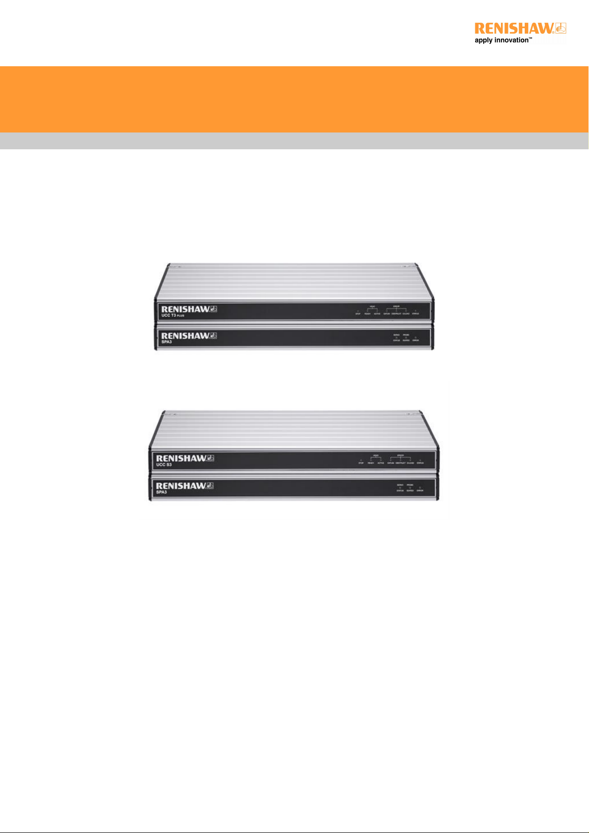
Front panels
UCC T3 PLUS
UCC S3
UCC T3 PLUS and UCC S3 CMM controller installation guide
http://www.renishaw.com
Issued 04 2014
10
Page 11

Rear panel layout
Key Description Connector polarity
1 Multiwire connection SOCKET
2 PICS SOCKET
3 Temperature compensation connector PLUG
4 Ethernet communications connector to CMM computer SOCKET
5 Reset button / IP configure button
6 Reserved - do not connect
7 PH10 head connector SOCKET
8 SCR200 rack input (TP200) SOCKET
9 RJ45 connector to SPA3 SOCKET
10 RJ45 connector to second SPA3 (not implemented at this time) SOCKET
11 Reserved
12 Reserved
13 Equipotential bond point BOLT
14 DC power jack 24 V SOCKET
UCC T3 PLUS and UCC S3 CMM controller installation guide
http://www.renishaw.com
Issued 04 2014
11
Page 12

Connecting the UCC T3 PLUS or UCC S3 to the host PC
Hardware connection
The host PC must have a dedicated Ethernet connection to the CMM controller. It is recommended that this is not a USB plug-in adapter
because of the reduction in speed these devices can produce.
If the host PC is connected to a network, it is necessary to install additional hardware to allow a dedicated connection for UCC T3 PLUS or
UCC S3 communication. For details on how to install additional hardware on the host PC, please refer to the manufacturer user's guide.
The CMM controller is capable of using 1 Gbps Ethernet (with appropriate cable).
A 5 m Ethernet cable is provided for this link as part of the CMM controller kit. The cable included is a Cat 5E, cross-over type. Other
lengths may be used, but the maximum length is determined by the generic specification for Ethernet connections.
It is recommened that a shielded Ethernet cable is used if there is a likelihood of EMC disruption due to the environment or location of the
routed cable.
It is recommended that the cross-over cable is labelled to avoid being mistaken for a non cross-over cable.
Software installation
UCCsuite 4.7 or newer software must be installed on the host PC prior to connection of the UCC T3 PLUS or UCC S3. The UCC software
suite can be downloaded from the Renishaw website. After the software has been installed, run UCCassist-2 to set up and configure the
CMM controller.
UCC T3 PLUS and UCC S3 CMM controller installation guide
http://www.renishaw.com
Issued 04 2014
12
Page 13

IP configure / reset button
Number 5 on the rear panel is the reset button which has two different functions. The function depends on the operational state of the
controller.
1. Pressing and releasing the reset button within fifteen seconds of switching on or rebooting the unit will force the controller into IP
configuration state.
2. Pressing and releasing the reset button after the download or whilst operating will cause the unit to restart.
To enter IP configuration state when the unit is already powered, press and release the reset button twice.
UCC T3 PLUS and UCC S3 CMM controller installation guide
http://www.renishaw.com
Issued 04 2014
13
Page 14

Installation and connection details
Dimensions
Width: 440 mm (17.3 in) Depth: 180 mm (7.1 in) Height: 44 mm (1.7 in) Weight: 2.1 kg (4 lb 10 oz)
UCC T3 PLUS or UCC S3 (CMM controller) can either be free standing or used in a 19 inch rack system.
CAUTION: Ensure the controller is disconnected from the power supply during installation.
Stand-alone installation
The CMM controller unit draws air from the right hand side when viewed from the front and expels air out of the left hand side. A minimum
clearance gap of 10 mm is necessary between the sides of the unit and any potential obstruction.
Mounting in a 19 inch rack
Therackmountingkit(RenishawpartnumberA55180005)containstwobracketsandfourM5×6mmscrews.Assemblethebracketsto
the CMM controller as shown below:
UCC T3 PLUS and UCC S3 CMM controller installation guide
http://www.renishaw.com
Issued 04 2014
14
Page 15

Earth connection diagram
PH10 head connector (15 way D-type socket)
NOTE: For maximum immunity from electrical noise, Renishaw recommends that:
1. Mating shells connectors must be metal bodied.
2. The overall cable screen is continuous and connected to the system ground on the user's equipment through the bodies of the
connectors.
CAUTION: For correct system function, the maximum overall single core resistance between the head and the controller MUST be
less than 2.5 ohm.
UCC T3 PLUS and UCC S3 CMM controller installation guide
http://www.renishaw.com
Issued 04 2014
15
Page 16

Probe head cable:
Machine cable:
UCC T3 PLUS and UCC S3 CMM controller installation guide
http://www.renishaw.com
Issued 04 2014
16
Page 17

Controller Controller Head Head Maximum
Signal name 15-way male D-type Cable PLM 6 - 9 14-way LEMO 12-core 14-way Current
B-axis feedback 14 Black (F) 1 (M) Yellow E n/a
Ground sense / head present 1 Brown (F) 2 (M) Red D n/a
DC reference 12 V 6 Violet (F) 3 (M) Brown C n/a
0 V 4 Green / red (F) 4 (M) Grey M 1000 mA
Locking motor 8 Vdc nominal 10 Green (F) 5 (M) White H 350 mA
A-axis motor 12 Vdc nominal 12 Red (F) 6 (M) Green L 350 mA
Not connected 2 Turquoise (F) 7 (M) Not connected - A-axis motor 12 Vdc nominal 11 White (F) 8 (M) Dark blue F 350 mA
B-axis motor / probe contact 7 Pink (F) 9 (M) Violet A 350 mA
B-axis motor / probe contact 15 Orange (F) 10 (M) Black B 350 mA
Screen Body Screen (F) 11 (M) Screen N, O A-axis feedback 3 Yellow (F) 12 (M) Orange G n/a
LED and datum 8 Blue (F) 13 (M) Turquoise J 15 mA
Motor / probe switch 5 Grey (F) 14 (M) Pink K 40 mA
NOTE: The male pins numbered 4 and 7 of the 14 way LEMO connector are linked together.
Renishaw head cables
Cable Name Part
number
Length Type Connector Connects to Connector Connects
to
Head cable PL5 A-1016-
7672
0.4 m to
0.8 m
Coiled PH10 type PH10 head 14-pin LEMO plug Machine
cable
Head cable PL6 A-1016-
7673
0.8 m to
1.6 m
Coiled PH10 type PH10 head 14-pin LEMO plug Machine
cable
Head cable PL12 A-1016-
7674
0.1 m Straight PH10 type PH10 head 14-pin LEMO plug Machine
cable
Head cable PL13 A-1016-
7675
0.1 m to
0.2 m
Coiled PH10 type PH10 head 14-pin LEMO plug Machine
cable
Machine
cable
PLM6 A-1016-
7564
6 m Straight 15-pin
D-plug
UCC T3 PLUS /
UCC S3
14-pin LEMO socket chassis
mount
Head cable
Machine
cable
PLM7 A-1016-
7563
4 m Straight 15-pin
D-plug
UCC T3 PLUS /
UCC S3
14-pin LEMO socket chassis
mount
Head cable
Machine
cable
PLM8 A-1016-
7677
6 m Straight 15-pin
D-plug
UCC T3 PLUS /
UCC S3
14-pin LEMO socket Head cable
Machine
cable
PLM9 A-1016-
7678
4 m Straight 15-pin
D-plug
UCC T3 PLUS /
UCC S3
14-pin LEMO socket Head cable
UCC T3 PLUS and UCC S3 CMM controller installation guide
http://www.renishaw.com
Issued 04 2014
17
Page 18

Temperature compensation connector (37 way D-type plug)
Pin number Description Pin number Description
1 Channel 1 input 20 Channel 1 return
2 Channel 2 input 21 Channel 2 return
3 Channel 3 input 22 Channel 3 return
4 Channel 4 input 23 Channel 4 return
5 Channel 5 input 24 Channel 5 return
6 Channel 6 input 25 Channel 6 return
7 Channel 7 input 26 Channel 7 return
8 Channel 8 input 27 Channel 8 return
9 Channel 9 input 28 Channel 9 return
10 Channel 10 input 29 Channel 10 return
11 Channel 11 input 30 Channel 11 return
12 Channel 12 input 31 Channel 12 return
13 Channel 13 input 32 Channel 13 return
14 Channel 14 input 33 Channel 14 return
15 Channel 15 input 34 Channel 15 return
16 Channel 16 input 35 Channel 16 return
17 Reserved 36 Reserved
18 Reserved 37 Reserved
19 Reserved Shell Screen
The thermistors for each channel connect between the CH input and CH return pins. The return signals are NOT zero volts and MUST NOT
be connected to any zero volt signal, GND or screen. Do not connect the return signals to anything else apart from the thermistor !
NOTE: For more information regarding the set up and usage of axis and work piece sensors, please read the temperature
compensation page of this installation guide.
PICS interface configuration
Configuration of the PICS (product interconnection system) is via UCCassist-2.
UCC T3 PLUS and UCC S3 CMM controller installation guide
http://www.renishaw.com
Issued 04 2014
18
Page 19

PICS
Renishaw's PICS allows a standard method of connection for real-time signals used by current Renishaw products.
Please refer to the PICS installation guide (Renishaw part number H-1000-5000) for further information when interfaces are fitted.
NOTE: TP7 is not supported with this product.
Stylus change rack (SCR) connector
The SCR200 stylus change rack is connected to the controller via a 6 pin miniature DIN socket. The pin numbers are illustrated and their
functions are shown in the table.
SCR200 connector (view on rear panel)
Pin number Description Pin number Description
1 Reset 4 +5 V
2 Fault 5 0 V
3 Inhibit 6 Reserved
Shell Screen
Cable lengths
UCC T3 PLUS / UCC S3 to SPA3 connection
The units must be linked by the supplied shielded CAT 5E 300 mm cable(s), no other cables are to be used.
Ethernet cable link to PC
This is a standard Ethernet CAT 5E cable, a 5 m cable is supplied as part of the CMM controller kit. Lengths up to 100 metres can be
used.
UCC T3 PLUS and UCC S3 CMM controller installation guide
http://www.renishaw.com
Issued 04 2014
19
Page 20

System interconnection diagrams
PH10 PLUS system with standard two wired touch-trigger probes
Key Description Key Description
1 Head cable(s) 4 SCR200 rack connection
2 RJ45 cable (supplied) 5 MCU connection
3 16 / 0.2 mm earth connection
PH10 PLUS system with multiwire scanning probes
Key Description Key Description
1 Head cable(s) 4 16 / 0.2 mm earth connection
2 Multiwire cable 5 MCU connection
3 RJ45 cable (supplied)
UCC T3 PLUS and UCC S3 CMM controller installation guide
http://www.renishaw.com
Issued 04 2014
20
Page 21

Temperature compensation
NOTE: Thermal compensation is activated and setup through UCCassist-2.
For installation and setup details refer to the TEC installation guide (Renishaw part number H-1000-5105).
UCC T3 PLUS and UCC S3 CMM controller installation guide
http://www.renishaw.com
Issued 04 2014
22
Page 22

Troubleshooting
Front panel LEDs
UCC T3 PLUS or UCC S3 visual diagnostics
Key to LED colour and behaviour:
LED Description
LED on
LED flashing off / on
LED flashing red / green
LED off
LED flashing red / blue
Name LED colour Function
STOP PHC10-3 PLUS asserting PICS STOP when lit
STOP
PI 200 asserting PICS STOP
HEAD READY Head ready for use when lit
HEAD ACTIVE Head indexing when lit
DATUM ERROR Head datum error when lit
OBSTRUCT ERROR Head obstruct error when lit
O/LOAD ERROR Head overload error when lit
UCC T3 PLUS and UCC S3 CMM controller installation guide
http://www.renishaw.com
Issued 04 2014
23
Page 23

Name LED colour Function
STATUS No LED - no power to UCC T3 PLUS / UCC S3 or downloadable unable to start, power cycle and try
again
STATUS Continuous LED - problem with comms link - reboot UCC T3 PLUS or UCC S3 and configure IP
STATUS Slow flash - waiting for download
STATUS Continuous light - download successful
STATUS Fast flash (5 Hz) - IP configuration mode
STATUS Dual flash - controller booting
STATUS Internal timeout - reboot UCC T3 PLUS or UCC S3
STATUS
Fast flash (5 Hz) - communications error - reboot required
STATUS Slow flash - scale error - reboot required
STATUS Slow flash - problem with download - reboot required (check file type eg UCC2)
STATUS Continuous LED - UCC T3 PLUS or UCC S3 overheated
STATUS Slow flash - unit does not have controller ID - return to Renishaw
STATUS
Fast flash (5 Hz) - no controller ID in IP configuration mode - return to Renishaw
NOTE: A scale error will cause the UCC T3 PLUS or UCC S3 to enter an error state which is not recoverable within a metrology
application environment. If a scale error occurs it will be necessary to reinitialise the installation due to the possibility of lost scale
counts and metrology being effected.
This section on troubleshooting is a guide to problems associated with the installation and integration of the PH10 system only. Refer to the
'PH10 PLUS installation and user's guide' (Renishaw part number H-1000-5070) regarding problems associated with normal operation of
the PH10 system.
The UCC T3 PLUS or UCC S3 will assert PICS STOP under the following conditions:
Condition Notes
Overload error Head has been overloaded when locked, causing it to unlock.
Obstruct error Head has been obstructed when moving to requested position or is unable to lock into it.
Head disconnect Head removed, cables disconnected, cable break
Datum error The head has failed to lock up correctly.
Pressing and releasing the E-STOP button will clear the PICS STOP providing the cause has been addressed.
Use the tables below to identify problems you are experiencing with your PH10 PLUS system. If you experience problems which you are not
able to identify or solve satisfactorily, please contact Renishaw for further advice.
No head movement in automatic mode:
Possible cause Solution
Cable / connection fault Check connection and integrity of cabling between head and controller.
UCC T3 PLUS and UCC S3 CMM controller installation guide
http://www.renishaw.com
Issued 04 2014
24
Page 24

No probe signal from PH10 PLUS:
Possible cause Solution
Cable / connection fault Check connection and integrity of cabling between head and controller.
Multiwire bypass connector not
fitted
Fit a multiwire bypass connector which will permit a standard touch-trigger probe signal to reach
controller.
Multiwired probe in use (SP25M) Check that the multiwire cable is correctly fitted to the head.
Check that the trigger output to the CMM controller is connected to the multiwired probe interface.
Poor measurement performance assiociated with the PH10 PLUS:
Possible cause Solution
Loose mounting of head Ensure all mounting screws are tight and mounting to CMM is secure.
Probe damping enabled during measurement Ensure probe damping is not enabled during measurement moves.
Stylus is too close to the surface before taking point Increase standoff distance in program.
UCC T3 PLUS and UCC S3 CMM controller installation guide
http://www.renishaw.com
Issued 04 2014
25
Page 25

Maintenance
WARNING: Maintenance should only be carried out after the machine has been isolated from the electrical supply, compressed air
supply or other energy sources in accordance with the machine manufacturer's instructions.
Periodically check that all mounting screws and electrical connectors are securely tightened. Electrical safety checks should include
inspecting the mains cable for damage and the safety of the connections. Periodical safety checks should also include the function of the
emergency stop system, including operation of all switches integrated into the system.
Remove dust from the external surfaces with a clean dry cloth as the unit is not sealed against liquid.
Filter replacement
UCC T3 PLUS or UCC S3 uses an internal air flow for cooling purposes. This system has a replaceable filter to minimise the ingress of
dust. The condition of the of the filter should be checked on a regular basis. It is recommended that this filter is removed and
checked/replaced as necessary or every 12 months.
The following procedure should be followed when replacing the air filter:
Remove power from the controller
Remove the 19 inch rack mounting brackets (if fitted) by removing the two fixing screws (not shown)
Pull the head of both the filter retaining clips away from the unit so they disengage
Pull away the external filter cover
Remove the filter material from the filter recess
Replace the filter using the reverse of the method given above (the replacement filter part number is A-5518-0011)
Advisory
It is recommended that periodical metrology tests are performed in order to identify any faults in subsystems eg air bearings, structure,
cables, software etc.
UCC T3 PLUS and UCC S3 CMM controller installation guide
http://www.renishaw.com
Issued 04 2014
26
Page 26

For worldwide contact details,
please visit our main website at
www.renishaw.com/contact
Renishaw plc
New Mills, Wotton-under-Edge,
Gloucestershire, GL12 8JR
United Kingdom
T +44 (0)1453 524524
F +44 (0)1453 524901
www.renishaw.com/cmmsupport
Issued 04 2014
 Loading...