

Renishaw UCC MMI Installation Manual
UCC MMI installation guide
Documentation part number: H-1000-5362-01-A
UCC MMI installation guide
http://www.renishaw.com
Issued 11 2017
1
General information
©2017Renishawplc.Allrightsreserved.
This document may not be copied or reproduced in whole or in part, or transferred to any other media or language, by any means, without
the prior written permission of Renishaw.
The publication of material within this document does not imply freedom from the patent rights of Renishaw plc.
Disclaimer
RENISHAW HAS MADE CONSIDERABLE EFFORTS TO ENSURE THE CONTENT OF THIS DOCUMENT IS CORRECT AT THE DATE
OF PUBLICATION BUT MAKES NO WARRANTIES OR REPRESENTATIONS REGARDING THE CONTENT. RENISHAW EXCLUDES
LIABILITY, HOWSOEVER ARISING, FOR ANY INACCURACIES IN THIS DOCUMENT.
Trademarks
RENISHAW® and the probe emblem used in the RENISHAW logo are registered trademarks of Renishaw plc in the UK and other
countries.
apply innovation is a trademark of Renishaw plc.
All brand names and product names used in this document are trade names, service marks, trademarks, or registered trademarks of their
respective owners.
Windows XP, Windows 2000, Vista, Windows 7 and Windows 10 are registered trade names of the Microsoft Corporation.
All trademarks and trade names are acknowledged.
WEEE
The use of this symbol on Renishaw products and/or accompanying documentation indicates that the product should not be mixed with the
general household waste upon disposal. It is the responsibility of the end user to dispose of this product at a designated collection point for
waste electrical and electronic equipment (WEEE) to enable reuse or recycling. Correct disposal of this product will help save valuable
resources and prevent potential negative effects on the environment. For more information, please contact your local waste disposal service
or Renishaw distributor.
Warranty
Renishaw plc warrants its equipment for a limited period (as set out in our Standard Terms and Conditions of Sale) provided that it is
installed exactly as defined in associated Renishaw documentation.
Prior consent must be obtained from Renishaw if non-Renishaw equipment (e.g. interfaces and/or cabling) is to be used or substituted.
Failure to comply with this will invalidate the Renishaw warranty.
Claims under warranty must be made from authorised service centres only, which may be advised by the supplier or distributor.
UCC MMI installation guide
http://www.renishaw.com
Issued 11 2017
2
Care of equipment
Renishaw probes and associated systems are precision tools used for obtaining precise measurements and must therefore be treated with
care.
Changes to Renishaw products
Renishaw reserves the right to improve, change or modify its hardware or software without incurring any obligations to make changes to
Renishaw equipment previously sold.
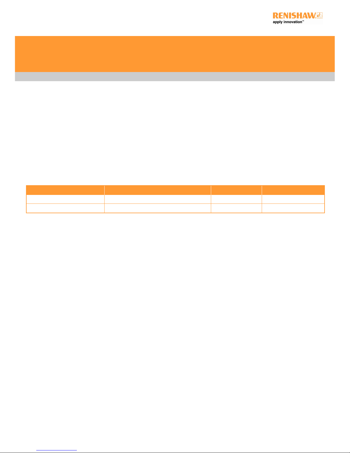
Packaging
To aid end user recycling and disposal the materials used in the different components of the packaging are stated here:
Packaging component Material 94/62/EC code 94/62/EC number
Outer box Cardboard - 70% recycled content PAP 20
Plastic bags Low density polyethylene bag LDPE 4
UCC MMI installation guide
http://www.renishaw.com
Issued 11 2017
3

EU declaration of conformity
Contact Renishaw plc or visit www.renishaw.com/productcompliance for the full EU declaration.
UCC MMI installation guide
http://www.renishaw.com
Issued 11 2017
4

FCC (USA only)
Information to user (47CFR section 15.105)
This equipment has been tested and found to comply with the limits for a Class A digital device, pursuant to Part 15 of the FCC rules. These
limits are designed to provide reasonable protection against harmful interference when the equipment is operated in a commercial
environment. This equipment generates, uses, and can radiate radio frequency energy and, if not installed and used in accordance with the
instruction manual, may cause harmful interference to radio communications. Operation of this equipment in a residential area is likely to
cause harmful interference, in which case you will be required to correct the interference at your own expense.
Information to user (47CFR section 15.21)
The user is cautioned that any changes or modifications not expressly approved by Renishaw plc or an authorised representative could void
the user's authority to operate the equipment.
Equipment label (47CFR section 15.19)
This device complies with part 15 of the FCC Rules. Operation is subject to the following two conditions:
1. This device may not cause harmful interference.
2. This device must accept any interference received, including interference that may cause undesired operation.
UCC MMI installation guide
http://www.renishaw.com
Issued 11 2017
5
Safety
If the equipment is used in a manner not specified by the manufacturer, the protection provided by the equipment may be impaired.
There are no user serviceable parts inside the equipment.
The UCC MMI controller is only warranted and approved for use with the provided PSU - Cincon TRG70A240-02E02
PSU electrical ratings
Supply voltage 100 V to 240 Vac +10%,-10%
Frequency range 50 Hz to 60 Hz
Power consumption 3 A
Output voltage 24 V
Transient voltages Installation category II
The UCC MMI is isolated from ac power by disconnection of the IEC mains connector from the supplied PSU. If any additional means of
isolation is required, it must be specified and fitted by the machine manufacturer or installer of the product. The isolator / disconnection
device must be sited within easy reach of the operator and comply with any applicable national wiring regulations for the country of
installation.
The UCC MMI is provided with an equipotential bonding point which must be used to connect it to the rest of the installations ground
structures.
UCC MMI installation guide
http://www.renishaw.com
Issued 11 2017
6
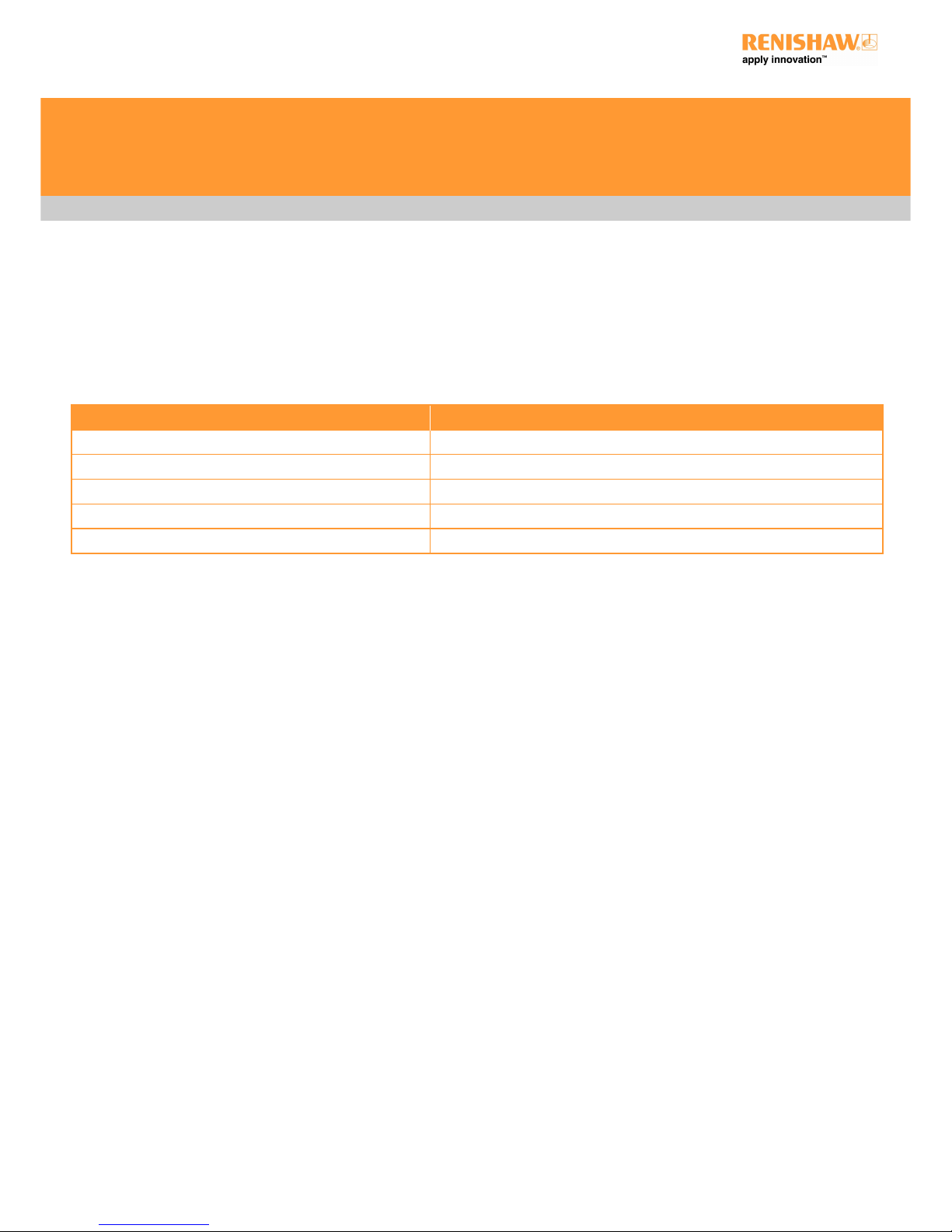
Environmental conditions
Indoor use IP30* (BS EN60529:1992)
Altitude Up to 2000 m
Operating temperature +5°Cto+50°C
Storage temperature 25°Cto+70°C
Relative humidity for storage 80%maximum(noncondensing)fortemperaturesupto+31°C
Lineardecreaseto50%at+50°C
Transient voltages Installation category II
Pollution degree 2
* NOTE: It may be necessary to house UCC MMI in a suitable enclosure according to the installation's environmental conditions to
obtain a higher IP rating.
UCC MMI installation guide
http://www.renishaw.com
Issued 11 2017
7

General wiring standards
To achieve reliable operation of the UCC MMI and the CMM host computer, the following should be observed:
Scale readhead signals, reference marks and error signals should comply with EIA RS-422A. It is recommended that each readhead
has its own screened cable and that these cables are kept well away from electrically noisy wiring.
All opto-isolated inputs and outputs should be separate from other connections to the UCC MMI controller, so that the CMM electrical
system is kept isolated from the circuitry within the controller, with the exception of the 0 V reference and protective grounding.
All signal cables MUST be screened and all cable screens should be connected electrically to the cable connector's metal shells. Cable
screens should only be connected to the protective earth (via the connector shell) at the UCC MMI end, and not directly connected to the
CMM protective earth. This is to avoid earth loops. However, the protective grounding must be continuous between the controller and all
other equipment in the installation. All cable connectors should be secured to the UCC MMI by the connector jack screws.
See also the installation instructions supplied with other Renishaw components in the system, i.e. probes or probe heads etc. Particular
attention should be paid to the screening and earthing methods of the cables carrying signals from probes.
NOTE: The UCC MMI electronics 0 V rail is connected to the overall ground plane at a star point within the UCC MMI.
Preparations
Before beginning the installation of the UCC MMI check the following items:
Ensure that all connecting cables, test equipment and software are available
Ensure that the CMM measuring scales / readheads are correctly installed and are functioning
Ensure that all the CMM status and limit switches etc. are correctly installed and have been function checked
Ensure that all power has been removed from the CMM and the host computer
UCC MMI installation guide
http://www.renishaw.com
Issued 11 2017
8

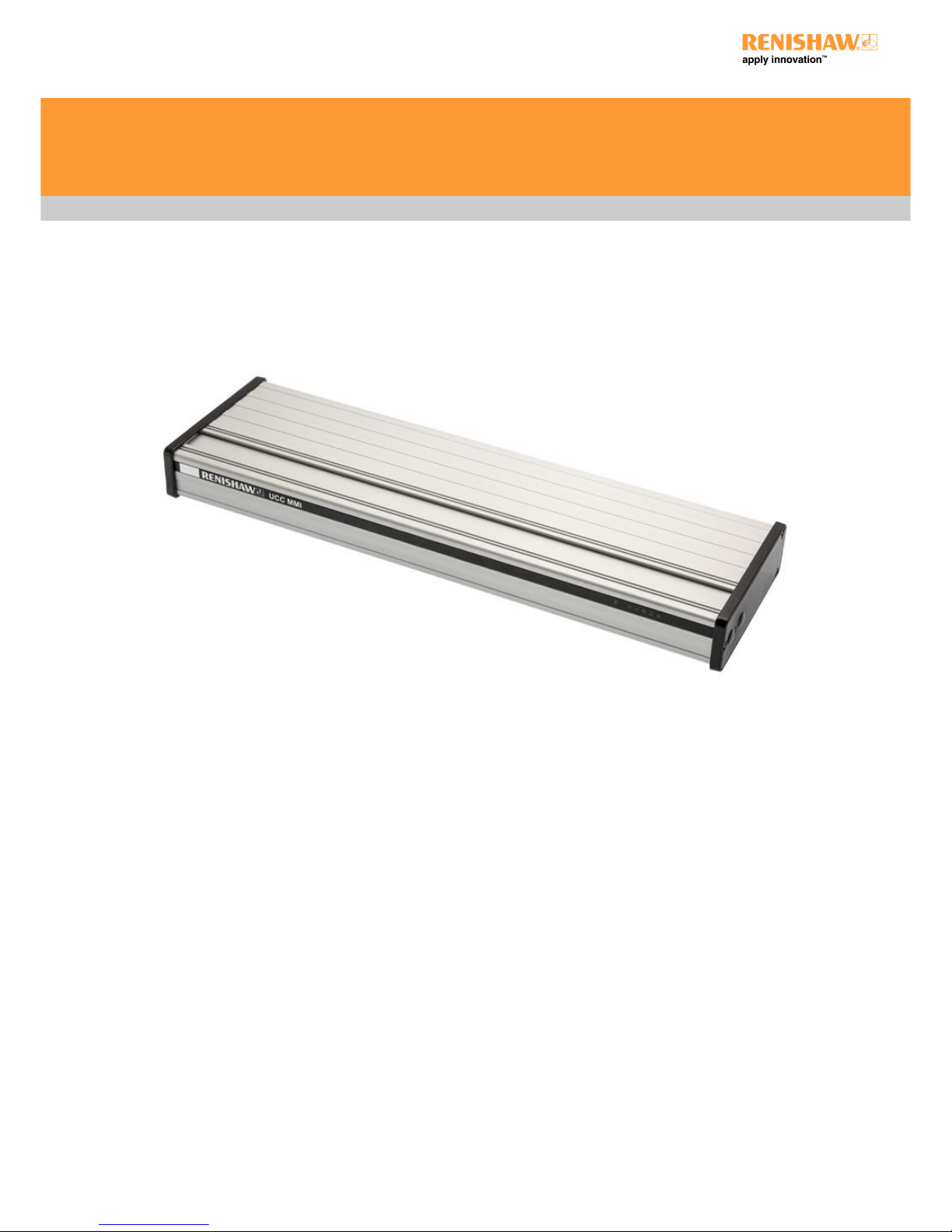
Introduction
The UCC MMI is an interface for use on manual CMMs to interface and connect encoder and probe signals to the PC. The complete range
of Renishaw 2-wire kinematic touch-trigger probes are supported.
The UCC MMI is housed in a 1U 19 inch rack-mountable enclosure. It is coupled to the CMM host computer by a USB 1.1 link and to the
CMM by external cable interface connectors. A rack mounting kit is available as an optional extra.
The UCC MMI has the capability to:
Control three axes of a CMM
Accept input signals from air pressure, contactor feedback and all axis inner and outer travel limit switches
Accept two uncommitted general purpose input signals and generate one uncommitted general purpose output signal
Directly support the TP1, TP2, TP6, TP20 touch-trigger probes
Indirectly support the TP200 via an external PI 200-3 interface
Provide a +24 V supply for use by the CMM if required.
UCC MMI installation guide
http://www.renishaw.com
Issued 11 2017
9
 Loading...