

Page 1
UCC2 universal CMM controller
Installation guide
H-1000-5223-04-B
EXTENDED WARRANTY
Now available for this product.
Contact your vendor.
www.renishaw.com/ew
Page 2

© 2004 - 2008 Renishaw plc. All rights reserved.
This document may not be copied or reproduced in whole or in part, or
transferred to any other media or language, by any means, without the prior
written permission of Renishaw.
The publication of material within this document does not imply freedom from
the patent rights of Renishaw plc.
Disclaimer
RENISHAW HAS MADE CONSIDERABLE EFFORTS TO ENSURE
THE CONTENT OF THIS DOCUMENT IS CORRECT AT THE DATE OF
PUBLICATION BUT MAKES NO WARRANTIES OR REPRESENTATIONS
REGARDING THE CONTENT. RENISHAW EXCLUDES LIABILITY,
HOWSOEVER ARISING, FOR ANY INACCURACIES IN THIS DOCUMENT.
Trademarks
RENISHAW® and the probe emblem used in the RENISHAW logo are
registered trademarks of Renishaw plc in the UK and other countries.
apply innovation is a trademark of Renishaw plc.
All brand names and product names used in this document are trade names,
service marks, trademarks, or registered trademarks of their respective owners.
Renishaw part no: H-1000-5223-04-B
Issued: 06 2008
Page 3

UCC2
Installation guide
Page 4

2 FCC
FCC
Information to user (FCC section 15.105)
This equipment has been tested and found to comply with the limits for a class A digital device, pursuant
to part 15 of the FCC rules. These limits are designed to provide reasonable protection against harmful
interference when the equipment is operated in a commercial environment. This equipment generates,
uses and can radiate radio frequency energy and, if not installed and used in accordance with the
installation manual, may cause harmful interference to radio communications. Operation of this equipment
in a residential area is likely to cause harmful interference, in which case you will be required to correct the
interference at your expense.
Information to user (FCC section 15.21)
The user is cautioned that any changes or modifications not expressly approved by Renishaw plc or
authorised representative could void the user’s authority to operate the equipment.
EC declaration of conformity
The UCC2 has been manufactured in conformity with the following standards:
BS EN 61326:1998 Electrical equipment for measurement, control and laboratory use – EMC
requirements.
Immunity to Annex A - industrial locations.
Emissions to class A (non-domestic) limits.
BS EN 61010-1:2001 Safety requirements or electrical equipment for measurement, control and
laboratory use.
Part 1: General requirements.
and that it complies with the requirements of the following EC Directives (as amended):
89/336/EEC - Electromagnetic compatibility (EMC)
73/23/EEC - Low voltage
Page 5

Care of equipment 3
Care of equipment
Renishaw probes and associated systems are precision tools used for obtaining precise measurements
and must therefore be treated with care.
Changes to Renishaw products
Renishaw reserves the right to improve, change or modify its hardware or software without incurring any
obligations to make changes to Renishaw equipment previously sold.
Warranty
Renishaw plc warrants its equipment for a limited period (as set out in our Standard Terms and Conditions
of Sale) provided that it is installed exactly as defined in associated Renishaw documentation.
Prior consent must be obtained from Renishaw if non-Renishaw equipment (e.g. interfaces and/or cabling)
is to be used or substituted. Failure to comply with this will invalidate the Renishaw warranty.
Claims under warranty must be made from authorised service centres only, which may be advised by the
supplier or distributor.
Machine safety
WARNING: Switching off or isolating the UCC2 may NOT prevent unexpected machine
!
movement. The user is advised to Isolate the machine from the electricity supply, compressed air
or other energy sources in accordance with the machine manufacturer's instructions before
entering the danger zone or performing any maintenance operations.
If the equipment is used in a manner not specified by the manufacturer, the protection provided by the
equipment may be impaired.
Trademarks
Windows 98, Windows XP, Windows 2000 and Windows NT are registered tradenames of the Microsoft
Corporation.
All trademarks and tradenames are acknowledged.
Page 6

4 References and associated documents
References and associated documents
It is recommended that the following documentation is referenced when installing the UCC2.
Renishaw documents
A full set of documents are supplied on Renishaw UCC software CD. Reference to the following
documents may be needed when installing a UCC2 system:
Document number Title
H-1000-5057 UCC controller programmer’s guide
H-1000-5058 UCC Renicis user’s guide
H-1000-5067 MCU1 installation guide
H-1000-5068 SPA1 installation guide
H-1000-5220 UCC daughtercard installation guide
H-1000-5222 UCC command set
H-1000-5227 SPA1 tuning guide
H-1000-5234 SPA2 installation guide
H-1000-5107 SPAlite user’s guide
External documents
National and international standards including the following may be applicable to the finished machine or
installation: -
EN 292-2:1991 (Safety of machinery - Basic concepts, general principles for design - Part 2: Technical
principles and specifications.
EN (IEC) 60204-1:1997 (Safety of machinery - Electrical equipment of machines - Part 1: General
requirements).
Page 7

Safety 5
Safety
Electrical requirements
The UCC1 is powered from the a.c. mains supply via an IEC 320 connector. The operating voltages of the
unit are as follows:
100 - 120 V ac and 220 - 240 V ac –15%, +10% 50/60 Hz ±5% 120 W maximum
This equipment must be connected to a protective earth conductor via a three core mains (line) cable. The
mains plug shall be inserted only into a socket outlet provided with a protective earth contact. Do not use
an extension cable without a protective conductor.
An earth stud is provided to allow bonding of the CMM’s metal parts to the protective earth.
CAUTION: Any interruption of the protective conductor may make the equipment dangerous.
!
Make sure that the grounding requirements are strictly observed.
Environmental requirements
The following environmental conditions comply with (or exceed) BS EN 61010-1:1993
Indoor use
Altitude
Operating temperature
Storage temperature
Relative humidity
Transient overvoltages
Pollution degree
NOTE: If a higher IP rating is required, an additional external enclosure will be required to house the
UCC2. This enclosure must facilitate an airflow to allow the internal temperature to maintain the ambient
within the operating temperature range.
IP30 (no protection against water)*
up to 2000 m
0 °C to +50 °C
-10 °C to +70 °C
80% maximum (non-condensing) for temperatures
up to +31 °C
Linear decrease to 50% at +40 °C
Installation category II
2
Page 8

6
This page intentionally left blank
Page 9

Contents 7
Contents
1 Introduction.......................................................................................................................................12
1.1 Overview ................................................................................................................................12
1.2 Literature ................................................................................................................................13
1.3 CMM host computer...............................................................................................................13
1.4 Installation software ...............................................................................................................14
1.4.1 Renicis ....................................................................................................................14
1.4.2 UCCassist™ ...........................................................................................................14
1.4.3 IP configurer ...........................................................................................................14
1.4.4 Licence manager ....................................................................................................14
1.5 Items supplied ........................................................................................................................15
1.5.1 UCC2 kits................................................................................................................15
1.5.2 UCC2 upgrade........................................................................................................15
1.5.3 UCC2 system accessories......................................................................................15
2 Description of the UCC2...................................................................................................................17
2.1 Motherboard...........................................................................................................................17
2.2 TP200 interface......................................................................................................................18
2.2.1 Differences between the PI 200 and the UCC2 interface .......................................18
2.2.2 Connectors .............................................................................................................18
2.3 SP25M and SP600 interface..................................................................................................18
2.3.1 Connectors .............................................................................................................18
2.4 Power supply unit...................................................................................................................19
2.4.1 Input........................................................................................................................19
2.4.2 Output .....................................................................................................................19
3 Connecting the UCC2 to the host PC...............................................................................................20
3.1 Hardware connection .............................................................................................................20
3.2 Software installation ...............................................................................................................20
3.3 Configuration of IP addresses................................................................................................21
3.3.1 IP addressing..........................................................................................................21
3.3.2 Setting the IP address of the PC ............................................................................22
3.3.3 Setting the IP address of the UCC2........................................................................24
3.3.4 Changing the IP address of the UCC2 ...................................................................27
3.3.5 Establishing a new UCC2-PC pairing .....................................................................27
3.4 Downloading ..........................................................................................................................27
Page 10

8 Contents
4 Connecting the UCC2 to a CMM..................................................................................................... 28
4.1 The controller’s 24 V supply .................................................................................................. 30
4.2 Motor engagement via SPA connector.................................................................................. 30
4.2.1 Amplifier enabling .................................................................................................. 31
4.2.2 Contactor energising.............................................................................................. 31
4.3 Motor command signals ........................................................................................................ 32
4.4 Motor command polarity........................................................................................................ 32
4.5 Brakes ................................................................................................................................... 32
4.6 Air solenoid............................................................................................................................ 33
4.7 Switched outputs ................................................................................................................... 33
4.8 Switched inputs ..................................................................................................................... 33
4.8.1 Limit switches......................................................................................................... 33
4.8.2 Amplifier OK and contactor feedback .................................................................... 33
4.8.3 Fatal fault ............................................................................................................... 34
4.8.4 Declutched mode ................................................................................................... 34
4.8.5 Uncommitted inputs ............................................................................................... 34
5 Connectors and signals................................................................................................................... 35
5.1 Overview ............................................................................................................................... 35
5.2 Ethernet connection .............................................................................................................. 35
5.3 CMM readhead input connections......................................................................................... 35
5.3.1 CMM readhead interface circuit ............................................................................. 37
5.3.2 Adjusting readhead supply voltage ........................................................................ 38
5.4 SPA2 connector A and B....................................................................................................... 38
5.5 Aux comms............................................................................................................................ 38
5.6 MCU connector ..................................................................................................................... 39
5.7 SCR200 connector ................................................................................................................39
5.8 PICS connector ..................................................................................................................... 40
5.9 Scanning probe connector .................................................................................................... 40
5.10 Servo power amplifier connector........................................................................................... 41
Page 11

Contents 9
5.10.1 +24 V dc..................................................................................................................42
5.10.2 Contactor ................................................................................................................42
5.10.3 ESTOP_C ...............................................................................................................42
5.10.4 Enable amps ...........................................................................................................42
5.10.5 ESTOP_A and ESTOP_B.......................................................................................42
5.10.6 Axis command signals ............................................................................................42
5.10.7 Command common ................................................................................................42
5.10.8 Reserved ................................................................................................................42
5.10.9 Contactor feedback.................................................................................................43
5.10.10 AMPs OK ................................................................................................................43
5.10.11 ESTOP tripped........................................................................................................43
5.10.12 0 V (24 V return) .....................................................................................................43
5.11 Machine I/O connector ...........................................................................................................44
5.11.1 +24 V DC ................................................................................................................45
5.11.2 UCC2 general purpose outputs ..............................................................................46
5.11.3 UCC2 general purpose inputs ................................................................................46
5.11.4 Amplifier OK input ...................................................................................................47
5.11.5 CMM declutch .........................................................................................................47
5.11.6 ESTOP tripped........................................................................................................47
5.11.7 Air pressure switch .................................................................................................47
5.11.8 Crash switch ...........................................................................................................47
5.11.9 Contactor feedback.................................................................................................48
5.11.10 Limit switches .........................................................................................................48
5.11.11 24 V return ..............................................................................................................48
5.12 Reset button...........................................................................................................................48
5.13 Daughtercard slots .................................................................................................................49
5.14 PCI interface slot....................................................................................................................49
6 Installation of the UCC2 components...............................................................................................50
6.1 General wiring standards .......................................................................................................50
6.1.1 Preparations ...........................................................................................................51
6.2 Installation of daughtercards ..................................................................................................51
6.3 Connecting UCC2 cables to and from CMM ..........................................................................51
6.4 Connecting the UCC2 mains supply ......................................................................................52
7 Mounting the UCC2..........................................................................................................................53
7.1 Stand alone mounting ............................................................................................................53
7.2 Mounting in a 19” rack............................................................................................................53
Page 12

10 Contents
8 Renishaw license key manager system .......................................................................................... 54
8.1 Using the Renishaw license key manager ............................................................................ 54
8.2 Ordering extra functionality/upgrading .................................................................................. 55
8.3 Obtaining the key .................................................................................................................. 55
8.4 Applying the key .................................................................................................................... 55
8.5 Demonstration mode ............................................................................................................. 55
8.6 Repairing upgraded systems................................................................................................. 56
8.7 Available functionality............................................................................................................ 56
8.7.1 Triggering............................................................................................................... 56
8.7.2 Scan 3.................................................................................................................... 56
8.7.3 I++DME.................................................................................................................. 57
8.7.4 Error reporting........................................................................................................ 57
9 UCC2 troubleshooting ..................................................................................................................... 58
9.1 Front panel LED displays ...................................................................................................... 58
9.1.1 UCC2 power not switched ON ............................................................................... 58
9.1.2 UCC2 power switched ON ..................................................................................... 58
9.1.3 Initialisation/test ..................................................................................................... 59
9.1.4 System file downloading ........................................................................................ 59
9.1.5 Servo active LED ................................................................................................... 59
9.1.6 Probe seated LED.................................................................................................. 59
9.2 Probe head LED configuration .............................................................................................. 60
9.3 Fault finding........................................................................................................................... 60
9.3.1 Fatal faults ............................................................................................................. 60
9.3.2 Motors will not engage/re-engage.......................................................................... 61
9.3.3 Poor positioning accuracy...................................................................................... 62
9.3.4 Controller will not respond to host PC.................................................................... 63
9.3.5 Motor stalling.......................................................................................................... 66
9.3.6 Machine overspeed report ..................................................................................... 66
9.3.7 Scale reading (‘grating’) failures ............................................................................ 67
9.3.8 Timing out during moves or scans ......................................................................... 69
9.3.9 Cannot start a move............................................................................................... 69
9.3.10 Cannot start a scan ................................................................................................ 70
Page 13

Contents 11
10 Specifications ...................................................................................................................................71
10.1 Physical specification .............................................................................................................71
10.2 Cable lengths .........................................................................................................................71
10.2.1 UCC2 to CMM measuring scale readhead .............................................................71
10.2.2 UCC2 to CMM servo power amplifier input ............................................................71
10.2.3 Ethernet cable link to PC ........................................................................................71
10.3 Scale readhead signal speed.................................................................................................72
10.4 Electrical power requirements................................................................................................72
10.4.1 Controller output supplies .......................................................................................72
11 System interconnections ..................................................................................................................73
11.1 Probing system interconnection .............................................................................................73
11.1.1 2 wire touch-trigger probe system ..........................................................................73
11.1.2 PH10 probe head and 2 wire touch-trigger probe system ......................................73
11.1.3 PH10 probe head and ‘multiwire’ probe system .....................................................74
11.1.4 PH10 probe head, ‘multiwire’ probe system and ACR1..........................................74
11.1.5 PH10 probe head and ‘multiwire’ probe system using external PHC10-2 ..............75
11.2 Servo amplifier interconnection..............................................................................................75
11.2.1 UCC2 and SPA1 .....................................................................................................75
11.2.2 UCC2 and SPAlite ..................................................................................................76
11.2.3 UCC2 and SPA2.....................................................................................................77
12 Fitting a UCC2 into a UCC1 installation ...........................................................................................78
12.1 Machine I/O connection .........................................................................................................78
12.2 Servo power amplifier connection ..........................................................................................78
12.3 Software compatibility ............................................................................................................79
12.3.1 UCC software release.............................................................................................79
12.4 Machine ini file .......................................................................................................................79
12.5 Installed PC............................................................................................................................79
13 Maintenance.....................................................................................................................................80
14 Testing and verification.....................................................................................................................81
15 Revision history ................................................................................................................................82
Page 14

12 Introduction
1 Introduction
The purpose of this chapter is to describe the UCC2 (universal CMM controller) and the available options.
1.1 Overview
The UCC2 is a further development in Renishaw’s CMM controller product range. Building on the UCC1
platform introduced over five years ago, the UCC2 offers additional capability and system performance.
The UCC2 further optimises measurement performance through closer probe integration and is suitable
for original equipment and retrofit installations.
With ever tighter tolerances, more complex components and increasing pressures on lead times, the
ability to acquire large volumes of measurement data, both accurately and rapidly, is key to manufacturing
competitiveness. The new UCC2 controller offers advanced adaptive scanning, allowing accurate known
part scanning at velocities limited only by the dynamic performance of the CMM. Speeds of over
500 mm/sec (20 in/sec) can be achieved.
UCC2 offers true multi-sensor integration, giving benefits for original equipment manufacturers (OEMs),
retrofit/re-builders and end-users requiring system upgrades. The controller is supplied configured for
touch-trigger operation and UCCserver™(I++DME) as standard. It can be upgraded to conventional 3axes scanning, Renscan3™, or 5-axis scanning, Renscan5™, by keying in a 16 digit code.
The complete range of Renishaw probe systems is supported; conventional contact, strain-gauge and
analogue scanning sensors, manual and motorised probe heads, probe and stylus changers, and the
latest developments in servo positioning systems. Other optical and video sensors can also be supported.
A key benefit of UCC2 is the simple integration of complex probe systems, for existing systems and future
developments, and is central to Renishaw’s future plans for sensor innovation. Future products will be
easily integrated via plug-in daughtercards, and because the UCC control software is downloaded from
the PC each time the system is switched on, software upgrades for new products are easily integrated.
The UCC2 comprises of a mains-powered controller in a rack-mountable enclosure with a micro-processor
based computer system. It is coupled to the CMM’s host computer by a network link, and to the CMM by
external cable interface connectors.
Page 15

Introduction 13
The UCC2 CMM controller has the capability of:
• Controlling four axes of a CMM (accepting digital readhead signals and generating four axes drive
motor control signals)
• Accepting input signals from emergency stop, air pressure, crash detector, contactor feedback,
amplifier faults and all axis inner and outer travel limit switches
• Generating seven uncommitted general purpose output signals
• Accepting six uncommitted general purpose input signals
• Providing a +24 V supply for use by the CMM switches
• Directly supporting the TP2, TP6, TP20, TP200 touch-trigger probes, also the SP25M and SP600
analogue scanning probes
• Other Renishaw probes can be integrated into the UCC2 system using plug-in daughtercards
• Directly supporting the Renishaw MCU1 joystick
• Directly supporting the Renishaw SPA2, SPAlite or SPA1 servo power amplifiers
1.2 Literature
A number of other manuals are available to assist with the installation of the UCC2 system and are
included on the UCC software CD ROM. Some of the more relevant ones are listed below:
Part number Title Description
H-1000-5068 SPA1 installation guide System connection details
H-1000-5234 SPA2 installation guide System connection details
H-1000-5058 Renicis installation guide System set-up and testing
H-1000-5057 UCC1 programmers guide Programming
H-1000-5222 Command set Programming
H-1000-5107 SPAlite user’s guide Operation
1.3 CMM host computer
For the installation of a UCC2 controller, the CMM’s host computer must use Windows NT (service pack 6
or later), Windows 2000 or Windows XP Pro as an operating system; a CD-ROM drive, and a hard disc
drive. The storage requirements of the UCC system are less than 500 Mbytes. The processor speed and
RAM requirements are not excessive, if the PC is supporting the operating system and application
software, it will almost certainly support the UCC controller operation.
The PC must have one free dedicated network (Ethernet) connection port available for the UCC2
communication. It is recommended that this NOT a USB plug-in adapter because of the reduction in
speed of operation these devices normally produce.
Page 16

14 Introduction
1.4 Installation software
1.4.1 Renicis
The Renishaw Renicis program is a utility to assist the engineer to install, commission and maintain a
CMM system based on the UCC2 controller.
It also has features which assist in the development of a software interface between any existing CMM
application program and the UCC2.
Please refer to the Renicis user’s guide (Renishaw part number H-1000-5058) for more information on this
product.
1.4.2 UCCassist™
The UCCassist software suite complements the Renicis software package offering the following additional
capabilities of:
• Basic machine system diagnostics
• Compatibility with Renishaw’s machine checking gauge, enabling the user to complete frequent
volumetric accuracy tests to ensure the CMM is running within the specified operational tolerances
• Automated CMM error mapping routines, when used in conjunction with the Renishaw ML10 laser
system
1.4.3 IP configurer
The IP configurer software utility is a stand-alone tool for checking and setting the IP address compatibility
of the UCC2 controller and application PC.
1.4.4 Licence manager
This is a stand-alone software utility which is used to check and update the licence for controller
functionality.
Page 17

Introduction 15
1.5 Items supplied
The part numbers of the UCC2 kits and upgrades are:
1.5.1 UCC2 kits
A-5121-0001 UCC2 (touch-trigger enabled)
Comprising:
• UCC2 controller
• 5 metre Ethernet (cross-over) cable
• CD ROM containing:-
• System literature
• UCC operating software
• COM dlls
• Renicis installation and diagnostic program
• IP configurer software
• Link logger
1.5.2 UCC2 upgrade
A-5121-0005 Renscan3™ scanning functionality upgrade
A-5121-0007 Renscan5™ scanning functionality upgrade
1.5.3 UCC2 system accessories
1.5.3.1 SPA2
The SPA2 servo power amplifier is designed specifically for use with the UCC2 product and offers a
comprehensive solution for most CMM installations.
1.5.3.2 SPAlite
The SPAlite servo power amplifier is designed specifically for use with the UCC2 product and offers a
solution for CMMs typically <1 m³.
1.5.3.3 MCU1
The MCU1 is a comprehensive joystick solution designed for use with the UCC range of controllers.
Page 18

16 Introduction
1.5.3.4 Daughtercards
Various daughtercards are available for integration with the UCC2 as listed below. The daughtercards,
which plug into sockets on the motherboard, are available as required by the CMM application.
The UCC daughtercard installation guide (Renishaw part number H-1000-5220) details all of these cards,
please refer to it for installation details.
• Joystick interface daughtercard; for use with OEM’s own analogue joysticks
• PH10 probe head (PHC1050) daughtercard
• PHS1 probe head daughtercard
• Additional axis daughtercard; configurable for use as, a rotary table interface, an additional (twin)
scale input, or a dual axis drive interface
• PICS/RS232 daughtercard; required to interface older (not integrated) product interfaces
• Temperature sensor daughtercard
• SP80 daughtercard
Page 19

Description of the UCC2 17
2 Description of the UCC2
2.1 Motherboard
The motherboard comprises:
• Central processor unit (CPU)
• System memory, I/O and interconnection logic
• On-board connectors for optional plug-in daughter-boards
• Rear panel connectors for the external interface cables to and from the CMM
• Rear panel network connection for the two-way communication link to the CMM host computer
• Readhead circuitry for CMM digital measuring scales
• Axis servo control circuits
• Status indicating LEDs
• Control electronics for probes and peripheral devices attached to the CMM
LEDs visible through the front panel of the UCC2 enclosure indicate the operational status of the UCC2.
Sub-circuits on the motherboard control the following interfaces through connectors on the rear panel of
the enclosure:
• Ethernet data link to the CMM host computer
• X, Y, Z and additional axis data input from the CMM readheads
• A communication loop (SPA-A and SPA-B) to the SPA2 servo power amplifier
• A communications port (CH1), reserved for use on future products
• An MCU1 joystick interface
• Supplies and control signals for an SCR200 stylus changer rack
• Connections for the TP200 and TP20 range of touch-trigger probes
• Power to and input signals from the Renishaw SP25M or SP600 analogue probes
• Signal outputs to the axis drive motors servo amplifiers of the CMM
• I/O connections to limit switches, air pressure and other digital inputs and outputs
• A reset switch
Page 20

18 Description of the UCC2
2.2 TP200 interface
The UCC2 motherboard incorporates the circuitry and software necessary to interface with a Renishaw
TP200 probe, and operate the associated SCR200 stylus changer rack. The UCC2 implementation of the
TP200 interface has the same automatic recognition of, and support for, conventional touch-trigger probes
such as TP20, TP1, TP2 and TP6.
2.2.1 Differences between the PI 200 and the UCC2 interface
• Most of the PI 200 configuration options (dil switches) have been replaced by UCC command
number 426, PIB200 configure interface
• Internal connections have been implemented to permit connection of the required PICS signals to
the PHC1050 daughtercard or an external probe head controller (via a PICs/RS232 daughtercard)
• The probe reset function is now activated by command number 427, PIB200 reset probe
• The interface status LEDs on the front of the PI 200, are replaced by the command number 428,
PIB200 read status. This provides interface status information from the UCC2
• No audio ‘beep’ signal is generated within the UCC2. If fitted, the joystick unit beeper can be used
for this function
2.2.2 Connectors
The 9-pin D-socket labelled ‘trigger probe‘ will accept TP200 or conventional probe signals and direct
them to the PI 200 interface on the UCC2 motherboard.
A 6-pin miniature DIN socket labelled ‘SCR200‘ is used for connection of a SCR200 rack.
2.3 SP25M and SP600 interface
The UCC2 motherboard incorporates the circuitry necessary to interface with the Renishaw SP25M and
SP600 probes.
The UCC2s implementation of the SP25M and SP600 interface has automatic recognition of, and support
for, Renishaw touch-trigger probes TP200 and TP20.
2.3.1 Connectors
The 15-pin D-socket labelled ‘analogue probe‘ will accept probe signals from Renishaw’s SP25, SP600,
TP200 and standard Renishaw touch-trigger probes, and direct them to the appropriate interface on the
UCC2 motherboard.
Page 21

Description of the UCC2 19
2.4 Power supply unit
The UCC2 controller has a shielded switched-mode power supply unit (PSU) which is mounted inside the
UCC2 enclosure.
The PSU supplies the UCC2 controller and can also supply power to the specified probes and readheads,
and the status switches of the CMM.
2.4.1 Input
The power supply has a universal a.c. input circuit. See safety statement at the start of this document.
2.4.2 Output
The UCC2 PSU provides protected low voltage d.c. supplies of +15 V, +5 V and –15 V for external
devices such as scale readheads, the SP600 probe etc.
These supplies share a common 0 V return which is connected at a star point within the UCC2 to the
protective ground of the AC supply and the UCC2 case.
The UCC2 also provides a +24 Vdc supply available for use by the CMM to power the status switches etc.
The return line of this 24 Vdc supply (which should be wired separately from the returns of the +15 V, +5 V
and –15 V supplies) is also connected to the a.c. supply protective ground at a star point within the UCC2.
Page 22

20 Connecting the UCC2 to a CMM
3 Connecting the UCC2 to the host PC
The following sections detail how to connect and configure the communication link between the UCC2 and
the host PC that is running either the UCC utilities or metrology application software.
3.1 Hardware connection
The host PC must have a dedicated Ethernet connection to the UCC2. It is recommended that this NOT a
USB plug-in adapter because of the reduction in speed of operation these devices normally produce.
If the host PC is also to be connected to a network, it is necessary to install additional hardware within the
host PC to permit a dedicated connection to be available for UCC2 communication. For details on how to
install additional hardware into the host PC, please refer to the PC’s installation / users guide.
The UCC2 is capable of using both 10 and 100 Mbps Ethernet, the selection being determined by the
capability of the network adapter to which it is connected. We recommend that you use a 100 Mbps
network adaptor.
A 5 m Ethernet cable is provided for this link as part of the UCC2 kit and is a Cat 5e, cross-over type.
Other lengths may be used, the maximum being is governed by the generic specification for Ethernet
connections (i.e. a hundred metres), which is sufficient for any CMM installation. It must be a cross-over
type for a single installation.
If you are concerned about EMC disruption due to your environment, or the routing of the cable, then the
use a shielded cross-over cable is recommended.
We suggest that you label your cross-over cable as a cross-over cable as it looks identical to a normal,
not-crossed-over, cable.
3.2 Software installation
The UCC software must be installed on the host PC, prior to connection of the UCC2.
The UCC software disc (A-1333-0080), version 6.0 and later, supports UCC2 installations.
After the software has been installed, one of the utility programs available is “IP Configurer”; which is used
to give the UCC2 an IP address, and establishes the pairing of the PC and the UCC2.
Another software utility that is installed is “Renicis”. It is important that for UCC2 installations you use
Renicis version 6.0, provided on the UCC software version 6.0 CD-ROM, or later versions.
Page 23

Connecting the UCC2 to a CMM 21
3.3 Configuration of IP addresses
This section describes the steps needed to connect your UCC2 to the host PC and configure the Ethernet
communication link.
NOTE: The examples used in this section are for Windows XP Professional and will vary for other
operating systems.
3.3.1 IP addressing
You have to decide what IP address to give to the UCC2. The key to this is to choose an IP address for
the UCC2 and an IP address for the PC’s network adaptor that are of the same network. What does this
mean? Well, firstly we must introduce sets of networks called network classes which are defined by their
IP address ranges:
class A 1.0.0.1 – 126.255.255.254
class B 128.0.0.1 – 191.255.255.254
class C 192.0.0.1 – 223.255.255.254
For class A networks, a network is defined by the first number.
For class B networks, a network is defined by the first two numbers.
For class C networks, a network is defined by the first three numbers.
If you choose to use IP addresses that belong to the class A network class, then you must be sure that the
first numbers are identical, e.g. 10.0.0.1 and 10.123.4.17. If you choose to use IP addresses that belong to
the class B network class, then you must be sure that the first two numbers are identical, e.g. 155.23.0.1
and 155.23.86.207. If you choose to use IP addresses that belong to the class C network class, then you
must be sure that the first three numbers are identical, e.g. 192.168.32.1 and 192.168.32.2.
A rule that always works is to choose ‘adjacent’ IP addresses from the ranges given above (by adjacent
we mean that the last numbers differ only by 1, e.g. 172.16.40.1 and 172.16.40.2).
NOTE: The last number must not be 0 or 255.
Page 24
22 Connecting the UCC2 to a CMM
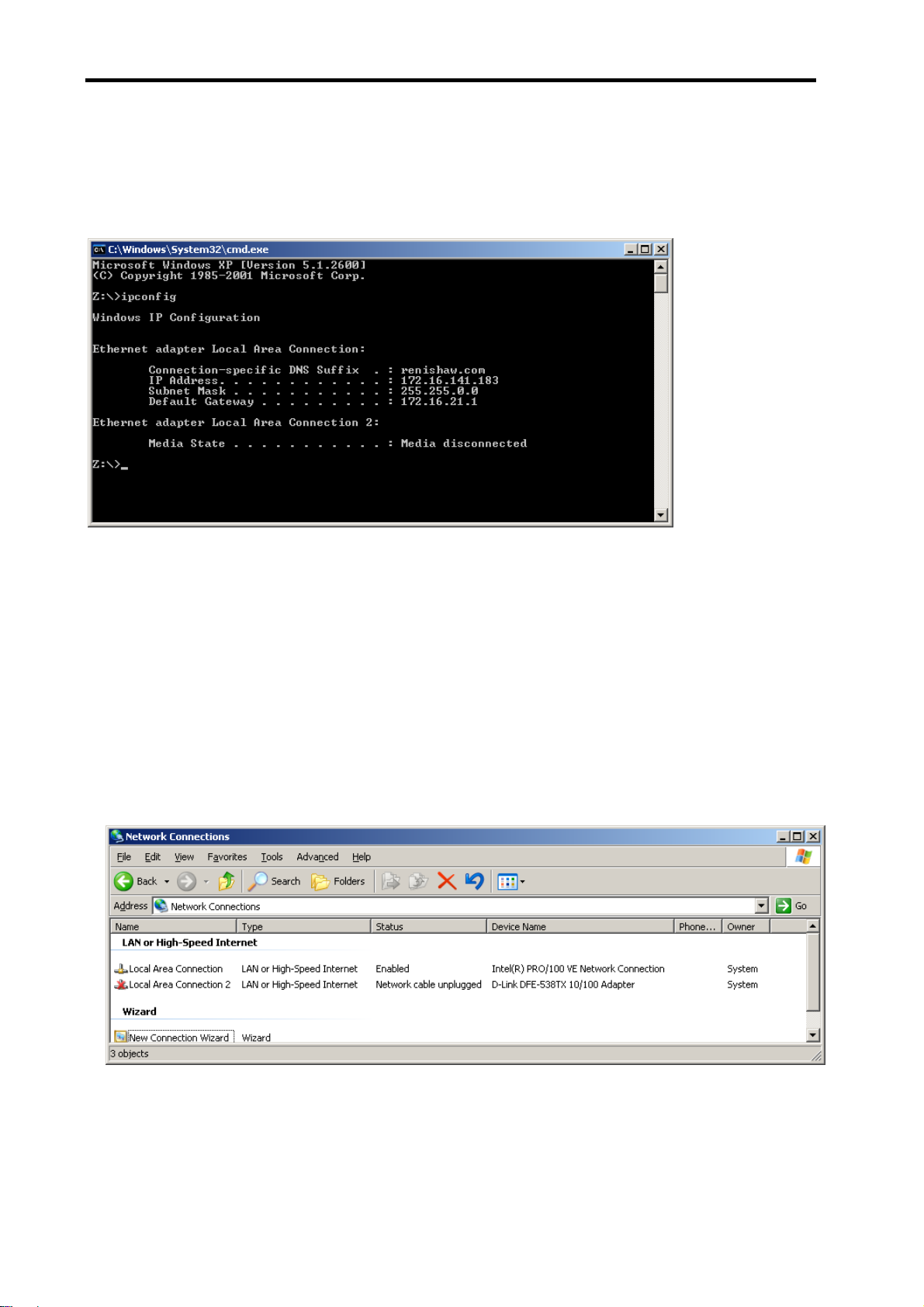
If there is more than one network connection in your PC, choose a network class for the UCC2-PC
connection that is not currently in use to keep the connections clearly separate. To find out which IP
address, and hence which network class your other network interfaces use, type “ipconfig” at a command
prompt. Its output will look similar to this:
Here the UCC2-PC network interface had its cable removed, so shows up as “Media disconnected”. The
other connection was the corporate one, and is seen to be a class B network. Hence the UCC2-PC
network is best chosen to be a class A or a class C one.
3.3.2 Setting the IP address of the PC
The network adapter in the PC to which the UCC2 is connected needs an IP address. See section 3.3.1,
“IP addressing” for a discussion of the choice. How to set the address in the PC varies with each version
of Windows, but the basic idea is the same. Here is the process using Windows XP Professional. You
need administrator rights in order to perform this operation.
a) Select Start → Settings → Control Panel → Network Connections to give:
Page 25
Connecting the UCC2 to a CMM 23
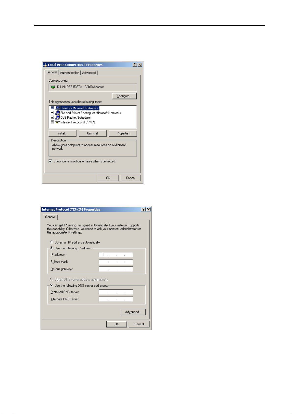
b) Right-click the appropriate Local Area Connection and select Properties from the resultant popup menu
box to give:
c) Select ‘Internet Protocol (TCP/IP)’ and click Properties to give:
Page 26
24 Connecting the UCC2 to a CMM
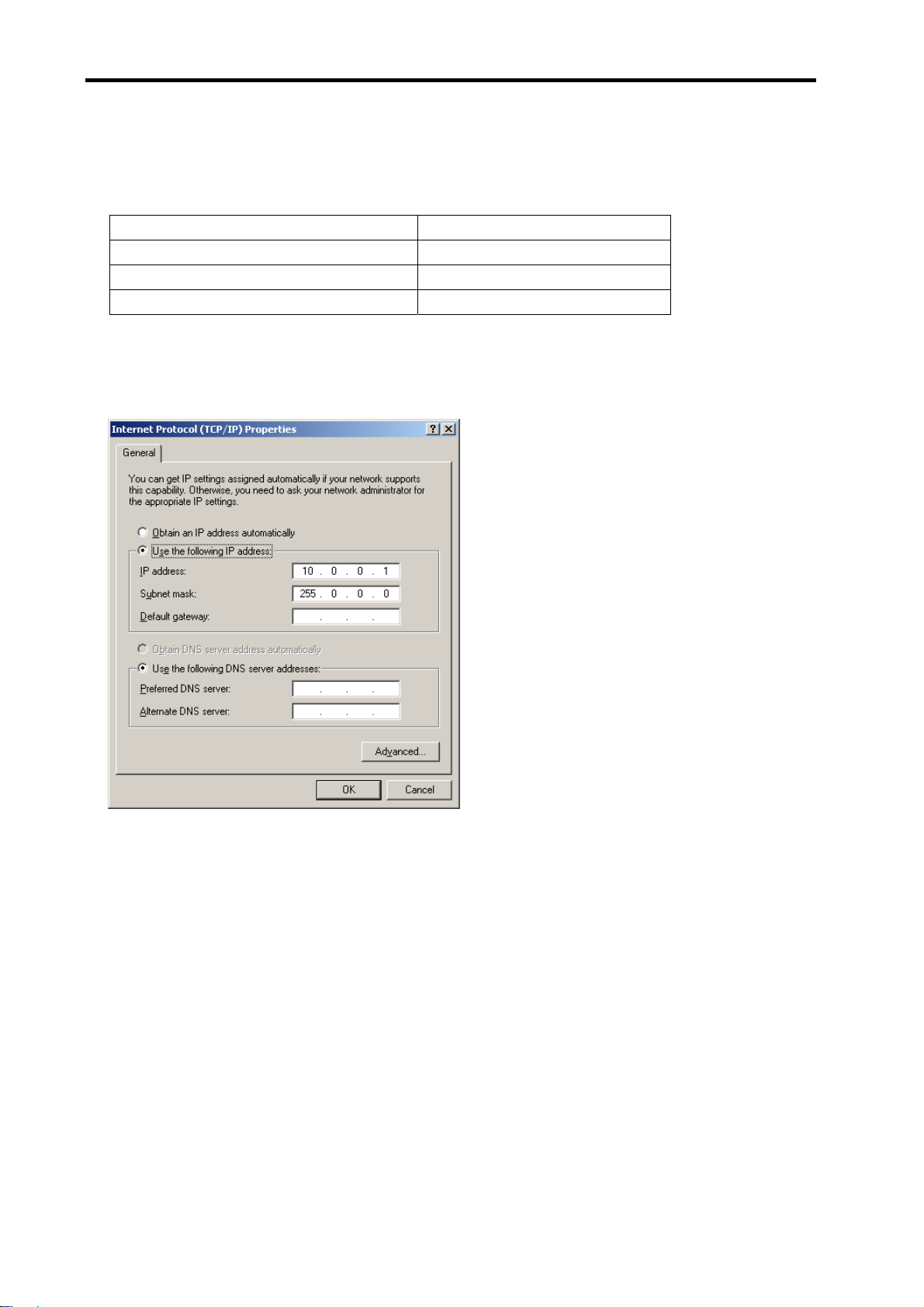
d) If not already selected select ‘Use the following IP address’ and type in the IP address that you want to
use for the PC end of the comms link. Now click in the Subnet mask field. On Windows XP the Subnet
mask will be filled in for you. If you have to fill it in for yourself, here are the values:
Class of network IP address belongs to Subnet mask to use
A 255.0.0.0
B 255.255.0.0
C 255.255.255.0
Leave the Default gateway field blank.
Example:
e) Click OK and then OK again. Whether or not this setting has taken effect depends on the version of
Windows that you are running. On earlier versions you will need to reboot the PC. To be absolutely
sure, reboot your PC anyway.
3.3.3 Setting the IP address of the UCC2
The UCC2 is not intended to be used on a corporate network. It is extremely important that this setting of
the IP address of the UCC2 is on a dedicated connection. It is also important that the connection is not
“firewalled” at the PC end. You need administrator rights in order to perform this operation.
When it is first installed the UCC2 does not have any IP address. Turn the UCC2 on and wait for it to boot
up. It will enter its IP configuration state, shown by the Error LED flashing rapidly. (Please be patient; this
will take about 15 seconds.)
Now start the UCC IP configuration software on the PC.
Page 27

Connecting the UCC2 to a CMM 25
a) Start → UCC Software → IP Configurer
b) Click on the drop-down icon and select the IP address of the network adapter into which the UCC2 is
plugged. (This should be the one on which you set the IP address of in section 3.3.2.)
Page 28

26 Connecting the UCC2 to a CMM
c) You are now told that the UCC2 does not have an IP address:
d) Fill in the desired IP address – the IP Configuration software has given you a head start by filling in the
network part of the address appropriate for the network adapter you have selected. (See section 3.3.1,
“IP addressing” for a discussion of the choice and of IP addresses in general.)
e) Click on ‘Configure PC and UCC pair’. If all is well this will result in a confirmatory dialogue box:
Page 29

Connecting the UCC2 to a CMM 27
The UCC2 will now have moved into its ‘waiting for download’ state – shown by the error LED flashing
slowly.
You have established the UCC2-PC system using the IP addresses of section 3.3.2 and this section.
NOTE: Whenever you change one of the items in this pairing, e.g. by connecting a different UCC2 to the
PC, you must re-run the UCC2 IP configuration software to establish the new UCC2-PC system.
3.3.4 Changing the IP address of the UCC2
If the UCC2 has an IP address, after booting up it skips its IP configuration state and proceeds into waiting
for a download, shown by the error LED flashing slowly. There are two ways to force the UCC2 into its IP
configuration state:-
a) During the 15 second power up phase, before the error LED comes on, press and release the Reset
button on the rear of the UCC2. At the end of the power up phase the error LED will flash rapidly
indicating it is in the IP configuration state.
b) If the UCC2 has already powered up with the error light flashing slowly, i.e. about once per second, or
even if the control software has been downloaded, the reset switch will need to be pressed twice. The
first time to reset the controller then a second time, within 15 seconds, to force the IP configuration
state.
The UCC2 is now in its IP configuration state, and the UCC2 IP configuration software can be run on the
PC, selecting the appropriate network adapter required. The current IP address of the UCC2 will be
displayed. Type in the new one and click on ‘Configure PC and UCC pair’.
3.3.5 Establishing a new UCC2-PC pairing
If you connect a different UCC2 to your PC, or a different PC to your UCC2, or even if you modify the
network settings on the PC, you must ensure that they are a matched pair. To do this, go through the
procedure in section 3.3.2, even if you do not wish to change the IP address of the UCC2. (If the IP
address is already suitable, then you do not need to re-type it.) Clicking on ‘Configure PC and UCC pair’
will establish the new pairing.
3.4 Downloading
The name of the downloadable file is contrler.uca. UCC1 and other controller downloadables will not work
on a UCC2. Remember to change the name in any configuration settings appropriate for your front-end.
Your UCC2 system is now established.
Page 30

28 Connecting the UCC2 to a CMM
4 Connecting the UCC2 to a CMM
The purpose of this chapter is to describe the various connections available within the UCC2 design to
enable connection to a CMM.
This section reviews each UCC2 connection and gives comments on the preferred methods and available
alternatives.
Figure 1 - Suggested wiring to the servo power amplifier connection
Page 31

Connecting the UCC2 to a CMM 29
Figure 2 - Suggested wiring to the servo power amplifier connection
Page 32

30 Connecting the UCC2 to a CMM
4.1 The controller’s 24 V supply
This supply is available at both the servo power amplifier connector and the machine’s I/O connector for
use by the CMM signalling circuits. It has a relatively low current rating, see section 5.11, and is thus not
suitable for heavy loads.
Please use semiconductors or relays to interface with high power loads or to those which need electrical
isolation.
All inputs and outputs (excepting the optically isolated amp control signals) are referenced to this supply.
It is not a floating supply, the 24 V return line is connected to the controller’s chassis and to the mains
supply protective ground at a star point within the controller.
If there are any interconnections between this supply and any of the CMM’s supplies, there is a possibility
that an additional path to ground may be created.
A separate supply of similar voltage may be used for signalling purposes in place of the controller’s 24 V
supply but its negative rail must be connected to the controller’s 24 V return line.
4.2 Motor engagement via SPA connector
The controller will begin to engage the servo motors when instructed to do so by the host computer, if all
the operating functions are in a safe or acceptable condition.
Listed below are possible causes for the motor engagement to fail:
• The system has not yet been configured for motion (i.e. the machine, servo and move parameters
have not been sent to the controller)
• A fatal fault has been detected (refer to Renicis users guide, Renishaw part number H-1000-5058)
• The emergency stop system has been activated
• A PICS ‘stop’ signal is detected within the system
• The amplifier OK signal not asserted
• An open limit switch
• A present or previously present scale reading fault
The process is in two stages, amplifier enabling and contactor energising, with protective delays between
each stage.
Page 33

Connecting the UCC2 to a CMM 31
4.2.1 Amplifier enabling
The ‘amps OK’ signal produced by the amplifier control circuits is an indication to the UCC2 controller that
the servo power amplifiers are not faulty.
The controller will first ensure that all its motor demand signals are zero and will then try to enable the
power amplifiers by asserting the ‘enable amps‘ signal (servo power amplifier connector pin 4 or 5, figure
1). See chapter 6 for its electrical ratings.
This “enable amps”, signal will be held on for 0.1 second to allow the ‘amps OK’ signal, from the servo
power amplifier, to become valid. If this signal does not become valid (i.e. pin 19 of the machine I/O
connector is not pulled low) the controller will abandon the engagement process. If no error is detected
then the controller will wait for a further period of 1 second before beginning the next stage, to allow the
amplifiers to settle after any initial transients.
Figure 1 (section 4) is an example of the recommended circuits that can be used to drive the power
amplifier enable inputs and to generate the amps OK signal shown. The circuits that are used in the
installation will vary depending on the amplifiers’ requirements but must pull the ‘amps OK’ input (pin 19)
down if all amplifiers are operating correctly.
If the user wishes to signal amplifier failures individually to the main computer, it is recommended that the
uncommitted user inputs (machine I/O connector, figure 2) are used for this purpose.
If the installer of the CMM makes the decision that the amplifier enabling function is not needed, the
‘Enable amps (active low)’ signal could be connected directly to the ‘amps OK’ input signal. This will
provide immediate feedback to the controller during the amplifier enabling process and permit the next
stage to begin.
NOTE: This method is not recommended.
4.2.2 Contactor energising
After establishing that the amplifiers are working correctly, the controller will take the “contactor” signal (pin
2 of the servo power amplifier connector) low, this should be used to signal the servo power amplifier to
apply power to the motors. The controller will keep this output signal low for 0.2 of a second during which
it expects the ‘contactor feedback’ input (machine I/O connector pin 24) to be pulled low to indicate that
the motors are now powered.
If the ‘contactor feedback’ signal is not received in time, the contactor (pin 2 ) and the amp control signals
(pins 4+5) are turned off and the motor engagement process is stopped.
If the ‘contactor feedback’ signal is received within this 0.2 second window, the controller keeps all motor
commands at zero for another 1.0 second before allowing the servo system to begin operating. This is
intended to give further protection against sudden machine movements when engaging the motors.
Page 34

32 Connecting the UCC2 to a CMM
If the installer of the CMM makes the decision that the contactor energising function is not needed, the
‘contactor’ signal (pin 2) can be joined to the ‘contactor feedback’ input signal (pin 22). This will provide
immediate feedback to the controller during the contactor energising process and permit the next stage to
begin.
NOTE: This method is not recommended.
4.3 Motor command signals
The UCC2 controller generates complementary motor velocity command signals for each axis (X axis =
pins 8+9, Y axis = pins 10+11, Z axis = pins 12+13, 4th axis = pins 14+15).
Each motor velocity signal is capable of a swing of +/-10 Vs centred on a zero velocity command of 0 Vs.
A motor “command common” connection is provided to define this 0 V level (servo power amplifier
connector, pin 16, figure 1).
The motor command common signal is also connected to the 24 V supply return, the controller chassis
and the mains supply protective ground at a star point within the controller. Care may be required in its
application.
The controller’s setting up process (detailed in the Renicis users guide H-1000-5058) will help the user to
set his power amplifier gains such that the maximum command signal (+/- 10 V) will produce 125% of the
required maximum machine speed.
If complementary signals are not required, either of the motor command signals may be used as a single
ended input, referred to the motor “command common” line.
Each motor command signal has a series resistor of 1k ohm to protect the controller from inadvertent
damage and this will reduce the drive signal to the power amplifiers if their inputs are of low impedance.
The ‘RENICIS‘ setting up program provided with the controller will compensate for this automatically.
4.4 Motor command polarity
For each axis, the motor command +ve pin will go negative with respect to the command common line to
produce a positive change of position.
The motor command -ve pin will go positive at the same time.
4.5 Brakes
These outputs have not yet been activated. Do not make connections to these outputs.
Page 35

Connecting the UCC2 to a CMM 33
4.6 Air solenoid
This output has not yet been activated. Do not make connections to this output.
4.7 Switched outputs
The UCC2 has the following uncommitted switched outputs, please refer to section 5.11.2 for details :
There are 7 uncommitted outputs available on the UCC2 I/O connector, pins 6 to 12 are allocated to be
outputs 0 to 6 consecutively. The UCC does not directly control these outputs, it merely acts as a postbox. These outputs are controlled from the application software package via command 318 “Write to
controller port”.
These switched outputs are pulled up to the 24 V rail by a 20 k ohm resistor when inactive, and will be
pulled down to the 24 V return line via an NPN transistor when activated. There is an excess voltage
protective diode fitted internally to the controller.
The outputs can be activated by a command from the main computer to the controller. If not being used
they should be left open circuit.
4.8 Switched inputs
The UCC2 has the following controller switch inputs, please refer to section 5.11.3 for details:
There are 6 uncommitted inputs available on the UCC2 I/O connector, pins 13 to 18 are allocated to be
inputs 0 to 5 consecutively. The UCC does not directly read these inputs, it merely acts as a post-box.
These inputs are read by the application software package via command 279 “Read from controller ports”.
The controller provides 29 inputs of this type. See chapter 5 for their electrical ratings.
Each input is connected to an LED fed from the +24 V rail, and is activated by being pulled down to the
24 V return line. The LED is part of an opto-coupler which is used to give the controller some isolation
from unwanted electrical signals on the input wiring.
4.8.1 Limit switches
Sixteen inputs are allocated to limit switch signals, 8 inner and 8 outer. When a limit switch is not activated
(i.e. the machine is within its working range) these inputs should be connected to the 24 V return line by
the limit switch contacts. If the machine installation does not require the connection of the limit switches
the signals must be connected to the 24 V return line.
NOTE: Limit switches should be installed such that they will not be damaged in the event of overtravel.
Where necessary for safety related functions, they should be of the direct (or positive) operating type to
IEC 60947-5-1).
4.8.2 Amplifier OK and contactor feedback
The ‘amplifier OK’ and the ‘contactor feedback’ inputs have been discussed in sections 4.2.1 and 4.2.2.
Page 36

34 Connecting the UCC2 to a CMM
4.8.3 Fatal fault
Three ‘Fatal Fault’ inputs are provided: emergency stop, machine air pressure low and a ‘Crash Switch’
input. This last is intended for use with a sensing mechanism which detects an unintended contact
between the machine’s moving and fixed components. The controller monitors these inputs and will stop
the motors if one or more input goes open circuit or high. If not required these inputs should be connected
to the 24 V return line.
NOTE: The ‘emergency stop’ input is not a primary safety device, although the controller will stop the
motors as far as it can. Its main use is to allow the controller to inform the main computer, and hence the
operator, of the ‘emergency stop’ switch actuation. In addition it will prevent motor re-engagement if the
‘emergency stop’ switch is still activated. Where an electromechanical controlled emergency stop is
required, to IEC/ EN60204-1 category 0, it must be separately provided and external to the UCC2.
4.8.4 Declutched mode
The ‘CMM in declutched mode’ input is intended to tell the controller that the driving motors are
mechanically disconnected from the machine, and that the machine may be moved by some other means,
e.g. by hand. In this state, the motor commands will be kept at zero velocity until the machine clutches are
re-engaged, at which time the controller will resume servo control at the new machine position. For normal
servo operation, this input should be pulled down to the 24 V return line. If this function is not required, the
input should be connected to the 24 V return line.
4.8.5 Uncommitted inputs
The remaining six inputs are uncommitted and may be used as required. These signals are not used by
the controller and are simply passed to the main computer, on request. If not required these inputs should
be connected to the 24 V return line.
Page 37

Connectors and signals 35
5 Connectors and signals
The purpose of this chapter is to describe in detail the pin-outs of the connectors mounted at the rear of
the UCC2 controller and to show examples of relevant circuit diagrams for the input and output circuits.
5.1 Overview
The connectors on the rear panel of the UCC2 controller enclosure are shown below:
The pin-out of each connector, and its purpose, is described in the following sections.
5.2 Ethernet connection
This is a standard RJ45 connector providing the Ethernet connection between the UCC2 and the PC
hosting the application software. Connection between these two units must be made using a standard,
Cat 5e, cross-over type Ethernet cable.
5.3 CMM readhead input connections
The X, Y, Z and “4th Axis” measuring scale readhead input connectors are high density 15-way ‘D’
sockets.
The X, Y and Z axis scale readheads of the CMM must be connected to the relevant socket on the rear
panel of the UCC2 enclosure.
Similarly the 4th axis scale readhead (dual axis or rotary table capability), if required, must be connected
to the socket (marked 4
Suggestion: Label all readhead connectors to avoid cross connection, if removed and replaced in the
future.
th
axis) on the rear panel of the UCC2 enclosure.
The four CMM readhead sockets are wired to the same pin-out, suitable for direct connection to Renishaw
RGH22 and RGH24 scale readhead wiring.
NOTE: Other manufacturers’ readheads and interpolators may require an external adapter to enable
them to use the Renishaw standard readhead connector wiring. They may also not produce an error signal
to the RS-422 specification.
Page 38

36 Connectors and signals
The UCC2 supplies a servoed 5 V dc power supply for the readheads. See chapters 5.3 and 10.4 for
details.
If standard Renishaw cables are used, the recommended cable sizes are 3 m of head cable and 15 m of
extension cable, or an equivalent combination. That the head cable is 5 times the resistance of the
extension cable, e.g. 4 m of head cable and 10 m of extension cable.
Even with the servoed 5 V supply it is still important that the cable resistance is kept to less than 2 ohms.
CAUTION: The connection of the cabling should be such that the CMM’s movements, as reported
!
by the UCC2, are of the correct polarity i.e. machine movement in a positive direction along any
axis should give positive change of position as reported to the host computer by the UCC2
controller. Adjust this, if required, by reversing the inputs of the scale readhead signal (change
over +A with +B and –A with -B).
15
Figure 3 - Readhead connector, view on face of sockets (rear of plugs)
Pin number Function
1 External set up
2 0 V supply from UCC2
3 - Error
4 - Reference mark
5 - B signal
6 - A signal
7 +5 V supply from UCC2
8 +5 V sensing
9 0 V sensing
10 Limit switch P
11 + Error / limit switch Q*
12 + Reference mark
13 + B signal
14 + A signal
15 Inner screen
Shell Screen
10
15
6
11
* The UCC2 is capable of supporting both
single and dual limit-switch RG22
readheads. The electronic circuits can
interface either type without any
intervention but the correct type must be
set in the machine “ini” file. If dual limit
types are fitted pin 11 functions as the
second limit switch. If single types are fitted
then pin 11 becomes the +Error signal.
NOTE: The 0 V supply and the 0 V sensing leads are connected together at the readhead. The +5 V
supply and +5 V sensing leads are similarly connected at the readhead. It is important that all the cable
cores are connected to ensure the voltage drop is compensated for.
Page 39

Connectors and signals 37
5.3.1 CMM readhead interface circuit
The signals from a readhead or interpolator should be to EIA specification RS-422.
Figure 4 - UCC2 input circuit for CMM readhead – scale and reference mark inputs
NOTE: If error inputs are not used or the readhead type is RGH24, tie the +error input to 0 V and the –
error input to +5 V.
Figure 5 - UCC2 input circuit for CMM readhead – limit switch inputs
Figure 6 - UCC2 input circuit for CMM readhead – error input
Page 40

38 Connectors and signals
5.3.2 Adjusting readhead supply voltage
It is strongly recommended that the sense lines are connected to the readhead so that the adjustment of
the supply voltage, to compensate for cable drop, is automatic. However, there are some circumstances
where this is not practical and we have provided a manual method of boosting the supply voltage.
In the .ini file there is a section called ReadHeadPSU which contains three parameters per axis. These
parameters are termination type, enable and voltage.
Termination type – controls the controller readhead circuits to provide either AC termination (0) or DC
termination (1) [recommended].
Enable – This is set to 0 as a default which allows the normal automatic voltage servo to operate. If it is
set to 1, then the readhead supply voltage can be manually set.
Voltage – This is the manual readhead voltage setting. It is only read when the enable is set to 1 and the
allowable range is 5.0 V to 7.5 V.
NOTE: You must ensure that the voltage at the readhead is within the range 5 V ± 5% (i.e. must not
exceed 5.25 V).
5.4 SPA2 connector A and B
This a pair of standard RJ45 connectors that support the high speed communication links to and from the
SPA2 servo power amplifier. See SPA2 installation guide (Renishaw part number H-1000-5234) for
details.
5.5 Aux comms
This connector is reserved for future use, no connections should be made to it.
Page 41

Connectors and signals 39
5.6 MCU connector
This is a 9 pin D plug suitable for direct connection to the MCU1 joystick unit.
Pin number Function
1 Ground
2 RX_B
3 RX_A
2.0H X
5
9
1
6
4 TX_A
5 Reserved
6 +15 V
7 TX_B
8 ESTOP_B
9 ESTOP_A
Shell Screen
Figure 8 – MCU connector. View on face of
socket (rear of plug)
5.7 SCR200 connector
This is a 6 pin miniature DIN socket suitable for direct connection to the SCR200 stylus change rack.
Pin number Function
1 Remote reset
2 Error
3 Inhibit
4 Rack power
5 0 V
6 Not connected
Shell Screen
Figure 9 - SCR connector. View on face of
socket (rear of plug)
Page 42

40 Connectors and signals
5.8 PICS connector
This socket is intended for use with any of the range of Renishaw touch-trigger probes, including the
TP200. The connector is a 9 pin miniature D socket, pinout as follows:
Pin number Function
1 PICS STOP
2.0H X
5
1
2 PICS probe power off (PPOFF)
3 0 V
4 PICS LED anode
5 Probe signal
6 Reserved
7 PICS probe damping (PDAMP)
8 PICS LED off (LEDOFF)
9 Probe common
Shell Screen
9
Figure 10 - PICS connector. View on face of
socket (rear of plug)
6
5.9 Scanning probe connector
The plug on the cable from the analogue probe connects to the 15-way high-density ‘D’ socket on the rear
panel of the UCC2.
This socket is intended for use with the Renishaw TP2, TP6, TP20 and TP200 touch-trigger probes and
the SP25 and SP600 series of analogue scanning probes.
The pin-out of the socket is as follows:
Pin number Function
1 +5 V supply
2 Not connected
3 Probe common
4 B signal
5 C signal
6 +12 V supply
7 -12 V supply
8 Probe identification
9 Not connected
10 Overtravel
11 A signal
12 0 V reference
13 Touch-trigger probe signal
14 Fixed probe head LED cathode
15 Fixed probe head LED anode
Shell Screen
15
10
15
Figure 11 - Scanning probe connector. View on
face of socket (rear of plug)
6
11
Page 43

Connectors and signals 41
5.10 Servo power amplifier connector
The UCC2 has the ability to connect to either a SPA1 or 3
this 25-way D-type socket on its rear panel. A 24 V dc supply is also provided by the UCC2 through this
connector to energise the CMM status switch.
13 1
2.0H X 8.6W
25
Figure 12 - Servo power amplifier connector. View on face of socket (rear of plug)
Pin
number
1 +24 V dc Supply provided for use with CMM status switches 5.10.1
2
3 ESTOP_C ESTOP system - reset signal 5.10.3
4
5
6 ESTOP_A ESTOP signal from MCU1 / Joystick 5.10.5
7 ESTOP_B ESTOP signal from MCU1 / Joystick 5.10.5
8 -X command Differential output to CMM X drive motor 5.10.6
9 X command Differential output to CMM X drive motor 5.10.6
10 -Y command Differential output to CMM Y drive motor 5.10.6
11 Y command Differential output to CMM Y drive motor 5.10.6
12 -Z command Differential output to CMM Z drive motor 5.10.6
13 Z command Differential output to CMM Z drive motor 5.10.6
14 -4th axis command Differential output to CMM 4th axis drive motor 5.10.6
15 4th axis command Differential output to CMM 4th axis drive motor 5.10.6
16 Command common Reference line for power amplifiers 5.10.7
17 Reserved 5.10.8
18 Reserved 5.10.8
19 Reserved 5.10.8
20 Reserved 5.10.8
21
22 Contactor feedback Confirmation of contactor operation 5.10.9
23 Amps OK Confirmation from the servo amplifiers that they are ready 5.10.10
24 ESTOP tripped Indication from the SPA that the ESTOP signal is asserted 5.10.11
25 24 V return Common reference line for supply and contactor signals 5.10.12
Shell Screen
Function Description
Contactor
(active low)
Enable Amps
(active low)
Contactor
(active high)
Enable Amps
(active high)
Output signal to control motor contactor (active low) 5.10.2
Command to SPA to enable amplifiers (active low) 5.10.4
Output signal to control motor contactor (active high) 5.10.2
Command to SPA to enable amplifiers (active high) 5.10.4
rd
party servo power amplifier system through
14
Refer to
section
Page 44

42 Connectors and signals
5.10.1 +24 V dc
+24 V dc supply provided for the use of contactors, relays and other motor control circuits. Current limit
1.0 Amps
5.10.2 Contactor
This command is issued by the UCC2, to the SPA, to engage the motor contactor. This output signal can
drive the contactor directly providing its current consumption is within the output specification. This output
signal is available in both an active low on pin 2 and an active high on pin 5.
5.10.3 ESTOP_C
This is the ESTOP reset line from the servo power amplifier. It is made available to the UCC2 plug in
daughter-card slots for incorporation by products that need to be aware or pass on this signal’s status. It is
part of the “category 2” ESTOP system supported by the UCC2 and SPA2 controller system.
5.10.4 Enable amps
This is a command from the UCC2 to the SPA requesting it to enable its amplifiers. This output signal is
provided as both an active low signal on pin 4 and as an active high signal on pin 21.
5.10.5 ESTOP_A and ESTOP_B
These are the connections from the SPA ESTOP system to the joystick / MCU mounted emergency stop
switch. ESTOP_A is the high end and ESTOP_B is the return. The ESTOP_B signal is also made
available to the UCC2 plug in daughter-card slots for incorporation by products that need to be aware or
pass on this signal’s status. A rotary table is a good example of where it needs to be incorporated as part
of the ESTOP system.
5.10.6 Axis command signals
These outputs (pins 8 to 15) are the velocity demand signals for each axis from the UCC2 to the servo
power amplifiers. They vary over the range +10 V to –10 V.
5.10.7 Command common
An analogue reference zero is available to the servo power amplifiers but this signal is not used by our
SPA1 and SPA2 amplifiers although some third party units do require this reference. It is important that
this is not used as a 0 V return for digital signals because this will inject noise into the velocity demands.
This pin (16) should be left open circuit if not required.
5.10.8 Reserved
These pins (17 to 20) have high-speed serial communication driver / receivers connected to them, they
are intended for future development. It is important that these pins should be left open circuit.
Page 45

Connectors and signals 43
5.10.9 Contactor feedback
This is a confirmation signal from the motor contactor to the UCC2 that is has successfully operated and
the motors are now engaged. This signal was on the I/O connector (pin 24) for the UCC1 and is still
available on that connector on the UCC2 for backwards compatibility reasons.
5.10.10 AMPs OK
This is a confirmation signal (pin 23) from the servo amplifiers that they on and ready. It is produced as a
response to the Enable Amps command. This signal was on the I/O connector (pin 19) for the UCC1 and
is still available on that connector on the UCC2 for backwards compatibility reasons.
5.10.11 ESTOP tripped
This input (pin 24) is used to inform the UCC2 of the CMM ‘Emergency Stop’ condition (ESTOP). If the
input pin is pulled down to 0 V (24 V return) the UCC2 will assume that there is no emergency stop active
and allow the servo motors to be energised. This input is also on the I/O connector pin 21.
If the input pin is open-circuit or near +24 V the UCC2 will assume that the emergency stop is active and
will disable all motors and inform the host computer of the event.
NOTE: No motor can be enabled while this input is high or open-circuit.
5.10.12 0 V (24 V return)
This is the 0 V reference connection for all the digital and switching signals, unless otherwise stated the
0 V connections from all external devices should be connected to this line. This signal line is available on
pin 25 on the SPA connector and pins 37 and 44 of the I/O connector. It is taken to a star point within the
UCC2 controller where it is connected to protective ground, cable screens and all the internal supply 0 V
lines. The star point must be the only point that these different 0V and ground connections are made.
Page 46

44 Connectors and signals
5.11 Machine I/O connector
The plug on the cable from the CMM connects to the 44 way miniature (high density) socket on the rear of
the panel of the UCC2.
The input/output (I/O) signals to/from the UCC2 controller are:
• Emergency stop switch
• Machine air pressure switch
• Crash switch
• Contactor feedback
• X+ and X-, Y+ and Y-, 4th axis- and 4th axis+, Z+ and Z- inner and outer limit switches of the CMM
• General purpose outputs and inputs
• 24 V dc supply and return
Figure 13 - Machine I/O connector, view on face of socket (rear of plug)
Pin
number
1 +24 V DC Supply provided for use on CMM switches 5.11.1
2 Air solenoid Reserved for future use
3 X brake Reserved for future use
4 Y brake Reserved for future use
5 Z brake Reserved for future use
6 Output 0 General purpose output signal 5.11.2
7 Output 1 General purpose output signal 5.11.2
8 Output 2 General purpose output signal 5.11.2
9 Output 3 General purpose output signal 5.11.2
10 Output 4 General purpose output signal 5.11.2
11 Output 5 General purpose output signal 5.11.2
12 Output 6 General purpose output signal 5.11.2
13 Input 0 General purpose input signal 5.11.3
14 Input 1 General purpose input signal 5.11.3
15 Input 2 General purpose input signal 5.11.3
16 Input 3 General purpose input signal 5.11.3
17 Input 4 General purpose input signal 5.11.3
18 Input 5 General purpose input signal 5.11.3
19 Amplifier OK 5.11.4
Function Description
Refer to
section
Page 47

Connectors and signals 45
20 CMM declutch 5.11.5
21 ESTOP tripped 5.11.6
22 Air pressure Machine air pressure switch input 5.11.7
23 Crash Crash detector switch input 5.11.8
24 Contactor feedback Contactor input signal 5.11.9
25 X axis outer limit CMM X axis limit switch input 5.11.10
26 -X axis outer limit CMM X axis limit switch input 5.11.10
27 Y axis outer limit CMM Y axis limit switch input 5.11.10
28 -Y axis outer limit CMM Y axis limit switch input 5.11.10
29 Z axis outer limit CMM Z axis limit switch input 5.11.10
30 -Z axis outer limit CMM Z axis limit switch input 5.11.10
31 X axis inner limit CMM X axis limit switch input 5.11.10
32 -X axis inner limit CMM X axis limit switch input 5.11.10
33 Y axis inner limit CMM Y axis limit switch input 5.11.10
34 -Y axis inner limit CMM Y axis limit switch input 5.11.10
35 Z axis inner limit CMM Z axis limit switch input 5.11.10
36 -Z axis inner limit CMM Z axis limit switch input 5.11.10
37 24 V return
38 4th Axis brake Reserved for future use
39 +4th Axis outer limit CMM 4th Axis limit switch input 5.11.10
40 -4th Axis outer limit CMM 4th Axis limit switch input 5.11.10
41 +4th Axis inner limit CMM 4th Axis limit switch input 5.11.10
42 -4th Axis inner limit CMM 4th Axis limit switch input 5.11.10
43 Reserved Reserved for future use 5.11.7
44 24 V return
Shell Screen
Common reference line for input and
output signals
Common reference line for input and
output signals
5.11.11
5.11.1 +24 V DC
+24 V dc supply provided for the use of contactors, relays and other motor control circuits. Current limit
1.0 Amps.
Page 48
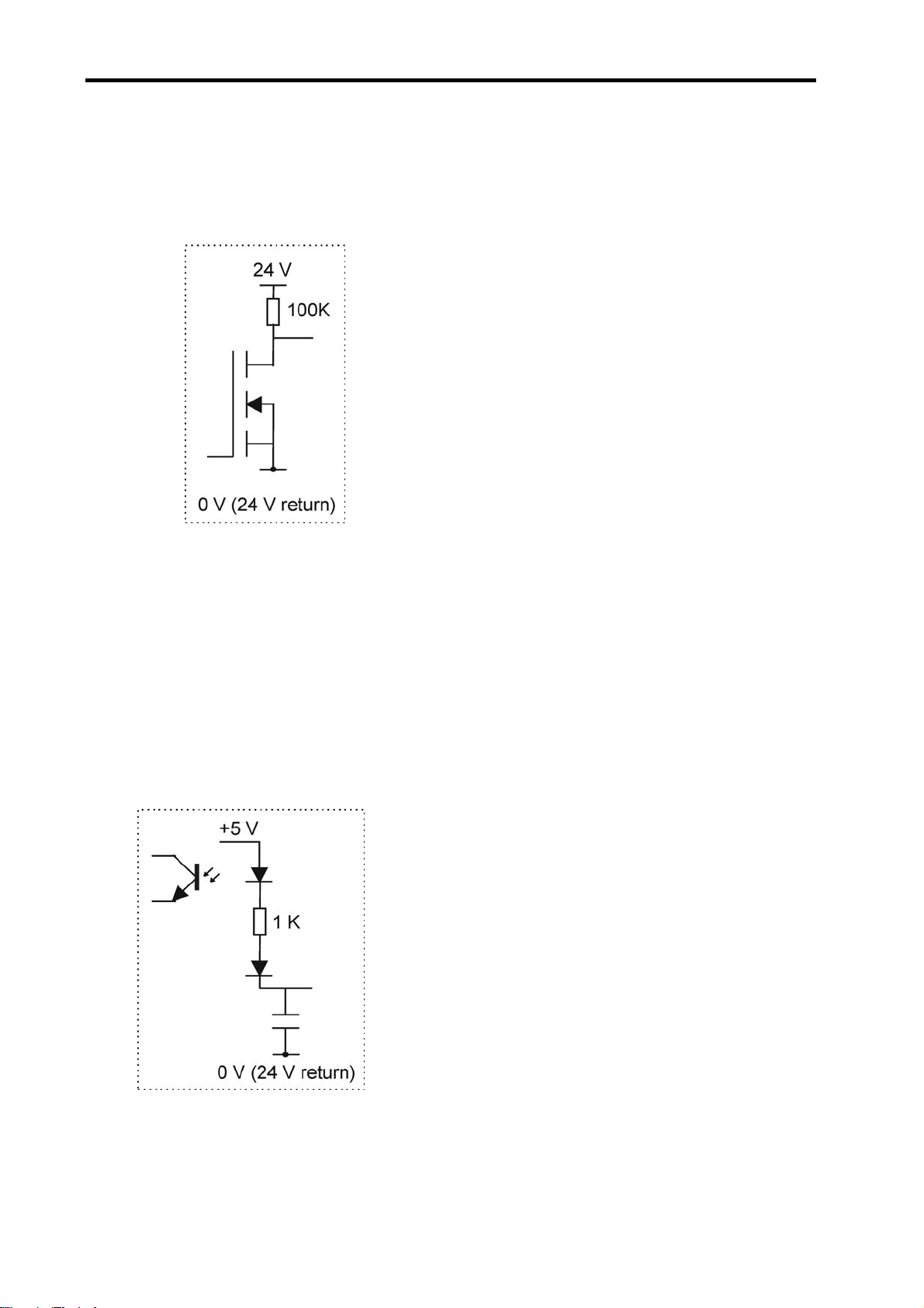
46 Connectors and signals
5.11.2 UCC2 general purpose outputs
These 7 transistor output signals (pins 6 to 12) are switched on and off by commands from the host
computer (See the UCC programmers guide, command number 318). The outputs are active low.
• Absolute maximum voltage rating 55 V dc
• Recommended maximum voltage 48 V dc
• Recommended maximum current 1.0 A
• The output is protected against higher currents
but the output state may change due to thermal
shutdown.
Figure 14
When the output is not activated the transistor is not switched on and the output pin is loosely pulled high
(+24 V) via a 100K resistor. When the output is activated, by sending a ‘1’ to the relevant control bit the
transistor will turn on, pulling the output pin down to the 24 V return line.
5.11.3 UCC2 general purpose inputs
These 6 opto-isolated LED inputs (pins 13 to 18) to the UCC2 can be used to send signals from the CMM
to the CMM host computer via the UCC2 (see the UCC programmers guide, command number 279).
Pulling an input pin low, towards the 0 V (24 V return line) will cause the controller to return a ‘0’ in reply to
the read command.
• Absolute maximum voltage rating 55 V dc
• Recommended maximum voltage 48 V dc
Figure 15
Page 49

Connectors and signals 47
5.11.4 Amplifier OK input
This signal (pin 19) is produced by the servo power amplifier to inform the connected UCC2 controller that
ALL the servo power amplifiers have been successfully enabled, it is an active low signal i.e. pulled to 0 V
(+24 return) to indicate success. This signal is a response to an active ‘amp control’ signal from the
controller. This signal is also available on the SPA connector pin 23.
5.11.5 CMM declutch
This input on pin 20 should normally be pulled down to the 24 V return line, to signal to the controller that
the CMM’s drives are mechanically connected to the moving elements of the machine, i.e. in their normal
condition. The input should be open circuit, or held high, when a CMM has been temporarily ‘de-clutched’
from its drive motors to allow manual positioning. The servo system will not drive the motors in this
condition and will resume control at the machine‘s position when the signal again goes low.
5.11.6 ESTOP tripped
This input (pin 21) is used to inform the UCC2 of the CMM ‘emergency stop’ condition (ESTOP). This
signal is also available on the SPA connector pin 24.
If the input pin is pulled down to the 24 V return line, the UCC2 will assume that there is no emergency
stop active and will allow the servo motors to be energised.
If the input pin is open-circuit or near +24 V the UCC2 will assume that the emergency stop is active and
will disable all motors, and inform the host computer of the event.
NOTE: No motor can be enabled while this input is high or open-circuit.
5.11.7 Air pressure switch
The machine air pressure input signal (pin 22) should be generated by a CMM air-pressure monitoring
transducer which should pull the input down to 0 V (24 V return line) if an adequate air supply pressure is
available.
This input is not pulled down, the UCC2 will disable all motors and will inform the CMM’s host computer of
the low air pressure.
This feature is not required, the input should be permanently connected to the 24 V return line.
5.11.8 Crash switch
This input signal (pin 23) is used to stop the CMM movement if there is a collision involving parts of the
CMM and probe system, as detected by a switching mechanism.
Page 50

48 Connectors and signals
The crash switch should pull the input down to the 24 V return line. If the input is not pulled down, the
UCC2 will disable all motors, and inform the CMM’s host computer of this state.
5.11.9 Contactor feedback
This input signal (pin 24) is used by the UCC2 to monitor the operation of the axes drive motors control
contactor. This signal is also available on the SPA connector pin 5.
When the contactor is energised (drive motors enabled), this signal should be pulled down to the 24 V
return line to indicate that motor power is available.
If the UCC2 has turned on the ‘contactor’ output (servo power amplifier socket, pin 2) and the signal on pin
24 indicates that the contactor has not operated, after a short delay the UCC2 will disable the drive motors
and inform the CMM host computer of this fault.
5.11.10 Limit switches
The UCC2 will use these input signals (pins 25 to 36 and 39 to 42) to stop the CMM as programmed by
the host computer (See the UCC programmers guide, command number 311).
All outer limit switches have to be closed before the CMM’s drives can be engaged. Operation of these
switches is interpreted as a fatal fault. If any of them is operated, all the CMM’s axes servo drive motors
are automatically disengaged. These signals cannot be overridden by a software command. Recovery
from an outer limit operation is either by manually pushing the machine “off” the limit switch or by a
separate override switch provided by the CMM’s manufacturer / retrofitter.
When a CMM actuates an inner limit switch on any of its axes, all CMM axes are decelerated, stopped
and backed off in the opposite direction as if it were a touch-trigger event. The inner limit switches can be
overridden by a software command for error mapping or collision recovery purposes, see command
number 311, control limit switch override, in the programmer’s guide.
5.11.11 24 V return
This is the 0 V reference for all of the I / O signals and is available on pins 37 and 44.
5.12 Reset button
The rear panel reset button has two different functions. Its function depends on what operational state the
controller is in.
a) If the unit has just been switched on and is in the stage before it is ready for download i.e.
approximately a 15 second window from switch-on, pressing and releasing this button will force the
controller into the IP configuration state. See section 3.3.3 for details.
b) If the controller is ready for download, or if the control software has been downloaded (in the
operational state), operation of this button will force a reset, i.e. the software will restart as if the unit
had been switched “off” then “on” again.
If you wish to enter the IP configuration state when the controller is ready for download, or is running the
control software, then two presses of this button, with a momentary pause between them, will achieve this
state.
Page 51

Connectors and signals 49
5.13 Daughtercard slots
Inside the UCC2 controller is a Renishaw proprietary bus system for connecting additional interfaces in the
form of daughter-cards. There is a wide range of additional interfaces available such as a PH10 controller,
a SP80 interface, an additional axis (rotary table or dual drive), a temperature interface, etc. This allows
the UCC2 to be correctly configured for the application for which it is being used, and also allows for the
integration future products.
5.14 PCI interface slot
This is an industry standard PCI interface slot. It is intended for future Renishaw advanced product
interfaces.
Page 52

50 Installation of the UCC2 components
6 Installation of the UCC2 components
The purpose of this chapter is to describe the procedure for installing the CMM’s controller, its
daughtercards and connections.
6.1 General wiring standards
To achieve reliable operation of the UCC2 and the CMM’s host computer, the following should be
observed:
WARNING: It is essential that the UCC2 controller is connected to a mains supply earth. The
!
recommended method of ensuring that the controller is earthed is to use the protective earth wiring
in the AC supply cable and connector:
Earthing provisions for the complete machine are the responsibility of the manufacturer or installer.
Isolation: UCC2 is isolated by removing the mains connector. It is the responsibility of the installer
or user to fit additional means of isolation if indicated by risk assessment.
Earth fault/residual current protection: It is the responsibility of the machine manufacturer or
product installer to ensure an adequate level of protection for the complete machine installation.
• Scale readhead signals, reference marks and error signals should comply with EIA RS-422A. It is
recommended that each readhead had its own screened cable and that these cables are kept well
away from electrically noisy wiring such as motor supplies, etc.
• All opto-isolated inputs and outputs should be separate from other connections to the UCC2
controller, so that the CMM’s electrical system is kept isolated from the circuitry within the controller,
with the exception of the 0 V reference and protective grounding.
• The analogue ground ( if daughtercard fitted) for a 3
dedicated only to that function.
• The analogue ground for the analogue probe connections should be dedicated only to that function.
• All signal cables MUST be screened and all cable screens should be connected electrically to the
cable connector’s metal shells. It is recommended that cable screens should only be connected to
the protective earth (via the connector shell) at the UCC2 and SPA end, and not directly connected
to the CMM’s protective earth. This is to avoid earth loops. However, the protective grounding must
be continuous between the controller and all other equipment in the installation.
rd
party joystick compatibility should be
• All cable connectors should be secured to the UCC2 by the connector jack screws.
Page 53

Installation of the UCC2 components 51
• See also the installation instructions supplied with other Renishaw components in the system, i.e.
probes or probe heads etc. Particular attention should be paid to the screening and earthing
methods of the cables carrying low level signals from either analogue or touch-trigger probes.
NOTE: The UCC2 electronics 0 V rail is connected to the overall ground plane at a star point within the
UCC2 and also to the protective ground of the AC supply.
6.1.1 Preparations
Before beginning the installation of the UCC2 check the following items:
• Ensure that all connecting cables, Ethernet link, daughtercards, test equipment and software are
available.
• Ensure that the CMM’s measuring scales/readheads are correctly installed and are functioning.
• Ensure that all the CMM status and limit switches etc. are correctly installed and have been function
checked.
• Ensure that all mains power has been removed from the CMM, CMM’s host computer, CMM servo
power amplifiers and CMM’s axis drive motors etc.
• Ensure that the CMM and the UCC2 are in their final positions and that all connecting cables are of
the required length.
6.2 Installation of daughtercards
WARNING: It is essential that full anti-static precautions are taken before working within the UCC2
!
controller enclosure.
To install a daughtercard please refer to the daughtercard installation guide, H-1000-5220
6.3 Connecting UCC2 cables to and from CMM
• Attach all CMM cable connectors to the mating sockets on the UCC2.
• Secure all cable connectors with the connector jacking screws to ensure physical and electrical
connection.
• Secure all cables for strain relief without reducing access for servicing.
Page 54

52 Installation of the UCC2 components
6.4 Connecting the UCC2 mains supply
• This installation must be undertaken by suitably experienced and / or qualified personnel.
• The UCC2 contains no user serviceable fuses. It is protected internally from inadvertent current
overload by self resetting fuses.
• There is no internal fuse on the mains supply of the UCC2. The installer must provide suitable
protection. The recommended fuse is a 5 Amp type T (anti-surge) to IEC60127/UL248-14, rated to
at least 250 V with a high breaking capacity. Its installation must meet the requirements of
IEC61010 and any applicable national wiring regulations for the country of installation.
• The UCC2 is isolated from AC power by disconnection of the IEC mains connector on the rear
panel. If any additional means of isolation is required, it must be specified and fitted by the machine
manufacturer or the installer of the product. The isolator must comply with IEC61010 and any
applicable national wiring regulations for the country of installation.
• The use of suitable RCD (residual current device), for automatic disconnection in the event of
insulation failure is recommended. This should be sited within easy reach of the CMM operator and
must meet the requirements of IEC61010 and any applicable national wiring regulations for the
country of installation.
Page 55

Mounting the UCC2 53
7 Mounting the UCC2
The UCC2 can be installed into either a 19” rack mount system or as a stand alone unit.
The location and mounting arrangement must take account of the environmental requirements for the
equipment and accessibility for cabling to the rear panel.
The dimensions of the units are:
Width: 440 mm
Height: 127 mm (3U)
Depth: 330 mm
7.1 Stand alone mounting
Four self adhesive rubber feet are supplied with the unit for stand-alone use.
7.2 Mounting in a 19” rack
To permit the UCC2 to be fitted into a 19” enclosure a rack mounting kit is required.
NOTE: The screws supplied with this kit are M5 × 6 mm countersink type. DO NOT replace with longer
screws as damage could occur.
The following procedure is recommended to fit the rack mounting brackets to the UCC2:
1. Position the UCC2 on a firm flat surface, with either the left or right hand side of the unit placed on
the surface and the front of the unit facing towards you.
2. Remove the blanking plugs from the side of the unit, there are two of these located about 15 mm
from the front lip on the enclosure and about 15 mm from the top and bottom of the enclosure.
3. Remove the rack mounting kit from its packaging and place one of the countersunk screws supplied
in the kit through one of the rack mounting brackets supplied.
4. Align this screw and mounting bracket assembly to the fixing holes in the side of the UCC2
enclosure, so that the rack mounting flange is flush with the front of the unit, and engage the screw
into the mating thread. Do not tighten at this point
5. Align the other fixing location in the rack mounting bracket with the fixing hole in the side of the
UCC2, and engage the other countersunk screw into the mating thread.
6. Tighten both countersunk screws to ensure a secure fixing.
7. Rotate the UCC2 such that the other side of the enclosure can be accessed and then repeat steps
2 to 6.
Page 56

54 Renishaw license key manager system
8 Renishaw license key manager system
The purpose of this chapter is to describe the Renishaw licence key manager system and the procedure
for enabling software upgrades.
The license key system has been designed to allow the OEM and retrofitters to easily upgrade UCC2
systems by simply entering in a licence key into the controller via the host PC. The upgrades can be done
in the OEM factory, or in the field, without the need for hardware dongles or additional extra inventory
(extra units configured for different functionality),
The license key system is based on a controller ID that is embedded into the UCC2 hardware. For each
UCC2 system there is a unique ‘key’ that is required to unlock the required functionality.
Figure 16- Renishaw licence key manager screen
This ‘key’ is provided by Renishaw, the process being explained below. Once this ‘Key’ is entered into the
UCC2, using the Renishaw license key manager software, it is stored in non-volatile memory. The UCC2
will remember the ‘key’ and so once a function is enabled it will remain enabled until a new function is
applied.
8.1 Using the Renishaw license key manager
When the UCC2 is received from Renishaw, it will be configured in the touch-trigger state and have the
I++DME active.
If only the touch-trigger system was purchased then no further action is required.
However, if additional functionality was purchased (or has been purchased since), the process of
upgrading the system must be conducted.
Page 57

Renishaw license key manager system 55
8.2 Ordering extra functionality/upgrading
Additional functionality can be enabled by the application of a new ‘key’. Before the ‘key’ can be issued by
Renishaw, an order for the upgrade must be placed.
Two pieces of information are required in this process.
1. The controller’s ID.
2. A valid order number for the required upgrade.
To read the enabled functions on a controller the connection must be made between the UCC2 and the
PC via the Ethernet link. No other connection to the UCC2, other than power, is required at this stage.
Using the Renishaw license key manager software, the controller ID number will be read from the system.
The format of the ID is an 8 digit number, hyphenated (e.g. xxxx-xxxx).
This number will be needed to request a new ‘key’ which will then enable the required function upgrade.
8.3 Obtaining the key
To obtain the ‘key’, the above information needs to be supplied to Renishaw. This can be done by e-mail,
fax or even by telephone. See www.renishaw.com.
They will have the capability to generate the unique key required for the unit in question, which will be
supplied in a 16 digit hexadecimal number of the form xxxx-xxxx-xxxx-xxxx.
8.4 Applying the key
Using the Renishaw license key manager software, the ‘new key’ button is clicked. The software then
prompts the user to enter the 16 digit key. Once entered, the ‘key’ is stored in the unit and will enable the
purchased upgrade. This can be checked by looking at the ‘enabled functionality’ table. The unit will
remember these settings even after it has been powered down.
8.5 Demonstration mode
A demonstration mode can be enabled giving 40 run time hours of all available functions.
The purpose of this is for sales demonstrations and short term evaluation. The ‘demo key’ is obtained from
Renishaw using the controller ID number. The key is generated in much the same way as the main key,
but is only 8 digits.
The ‘demo key’ is applied by clicking the ‘demo key’ button and entering the code.
Once the 40 hours have been used up, this ‘demo key’ becomes invalid. To use this function again a new
‘demo key’ must be obtained. It is intended that the ‘demo key’ is only used a limited number of times.
After this number Renishaw will be unable to issue further ‘demo keys’.
Page 58

56 Renishaw license key manager system
8.6 Repairing upgraded systems
If a unit is returned for repair and it is necessary to send a replacement / exchange unit back, then it will
arrive in the touch-trigger functionality state.
At this point, a new ‘key’ must be obtained. In this case the controller ID will be required and instead of an
order number, the repair number, GRA number or the serial number of the original unit returned is
required.
8.7 Available functionality
8.7.1 Triggering
Touch-trigger function supports touch-trigger operation with conventional trigger probes (e.g. TP2, TP6,
TP20, etc), electronic trigger probes (TP200, TP7, etc) and trigger operation of analogue probes (SP600,
SP25 and SP80).
8.7.2 Scan 3
Scanning mode supports all the functions offered by the triggering functionality (as specified above) as
well as surface measurement and part measurement modes using dedicated scanning routines.
Specifically these are: -
• Cylinder scan
• Gasket scan
• Grid scan
• Find centre
• RenscanDC
• 2D scan
• 3D scan
• 2½D scan
TM
Page 59

Renishaw license key manager system 57
8.7.3 I++DME
I++DME is an international standard for the command protocol used between an application software
package and a CMM controller. The application software uses an I++DME client and the controller uses
an I++DME server. Renishaw has produced an I++DME server for the UCC controller family (UCClite,
UCC1 and UCC2).
All controllers supplied after January 2006 have this capability activated.
8.7.4 Error reporting
If a command is sent to the UCC2 requiring functionality that is not enabled, the UCC2 will inform the
application software that the command has failed. It will give the ‘illegal command’ response and this will
then be handled by the application software.
Page 60

58 UCC2 troubleshooting
9 UCC2 troubleshooting
The purpose of this chapter is to provide assistance in diagnosing and rectifying system faults.
9.1 Front panel LED displays
To aid troubleshooting of the UCC2 system, five status LEDs are visible through the front panel of the
UCC2.
LED
{ = off z = on
Refer to section
on
Power
{ { { { { Power off 9.1.1
z { { { { Default start up condition. 9.1.2
ready
System
Servo
active
Probe
seated
System status
Error
9.1.1 UCC2 power not switched ON
All LEDs OFF.
9.1.2 UCC2 power switched ON
Power on LED is lit.
If switch-on is successful the UCC2 proceeds to the initialisation/test sequence.
Page 61

UCC2 troubleshooting 59
9.1.3 Initialisation/test
If the initialisation tests fail, then after about 15 seconds three LED configurations are possible, each
indicating a different form of failure:
Power on System ready Servo active Probe seated Error
on off off flashing slowly flashing fast
on off off off on
on off off off off
NOTE: These failures are not fixable at the customer’s site - if any of these forms of failure are indicated
the unit must be returned to your local Renishaw office.
NOTE: The state of all LEDs being off except ‘power on’ is the normal switch-on state (as per section
8.1.1); it only indicates failure if it remains like this beyond about 15 seconds.
Try switching the controller off, waiting about 10 seconds, then turning it on again. If the problem persists,
the unit needs attention.
If initialisation tests are successful, the power on LED will remain lit and the error LED will start flashing. A
slow flash (approximately 0.5 second period) indicates the system is ready for a download. A fast flash
(approximately 0.2 second period) indicates the UCC2 is in its IP configured state (see chapter 3.3).
9.1.4 System file downloading
During system file downloading, the power on LED is lit and the error LED is slowly flashing.
If the system file download fails then the power on, error and system ready (flashing) LEDs will be lit. In
this condition, the UCC2 waits for a system restart. Switch the controller off and after approximately
10 seconds switch it on again.
After a successful download the system is ready for use the power on and system ready LEDs will be lit.
9.1.5 Servo active LED
When the servo drives are not active, the servo LED is off.
When the servo drives are active, the servo LED is on.
9.1.6 Probe seated LED
When the probe is not deflected (in the case of analogue contact probes, not deflected beyond the trigger
threshold zone): probe seated LED is on.
When the probe is deflected: probe seated LED is off
Page 62

60 UCC2 troubleshooting
9.2 Probe head LED configuration
If a fixed ‘multiwire’ probe head such as a PH6M is connected to the UCC2, its trigger status LED is
controlled via the probe (multiwire) connection. When a motorised ‘multiwire’ probe head such as a
PH10M is in use the trigger status LED is controlled via the head (machine cable) connection.
The UCC2 automatically recognises which type of head is fitted and switches the connections accordingly.
Unlike the UCC1 no configuration switches are required.
9.3 Fault finding
9.3.1 Fatal faults
Some conditions can arise which mean that it is inadvisable or even dangerous to continue using the
CMM servo system. These are known in this document, and in the Renicis program, as ‘fatal’ faults, and
are as follows.
• A report of the emergency stop switch being active
• Air pressure is too low
• Crash switch operated, if fitted
• A scale reading failure
• An indicated overspeed (calculated from the rate of change of position)
• Outer limit switch active
NOTE: That other faults (not classed as fatal) can prevent the CMMs operation. Refer to following
sections.
Page 63

UCC2 troubleshooting 61
9.3.2 Motors will not engage/re-engage
Symptoms
Either the servo drives will not engage when the controller has been sent the ‘engage’ command, or the
drives have disengaged automatically and will not re-engage.
Possible causes (or reported causes)
After switch on, before the system is allowed to engage, it must be configured for motion (i.e. the machine,
servo and move parameters must be sent to the controller).
Any of the “fatal faults” will prevent the system from engaging, in addition the following will disengage the
servo motors.
• A reported failure from a servo power amplifier (amplifier feedback signal).
• The absence of the feedback signal from the motor contactor.
• The following list can also inhibit drive engagement or re-engagement.
• The probe being deflected
• Any outer limit switch being operated, or a soft limit exceeded.
• An active PICS STOP signal.
• Specifying the wrong probe type in the machine configuration, since open-circuit analogue probe
inputs may eventually drift to an apparently ‘deflected’ value.
Tests/cures
Check each of the above signals using the status flags returned to the host PC, and/or by confirming the
values of the actual signals reaching the controller.
Renicis can be used for further help with this by displaying the system status, the status bytes and the
PICS signals.
The amplifier and motor contactor feedback signals can also be examined using the ‘input signals’
window.
A PICS STOP signal may originate from an external accessory such as a probe head controller. If the
external device is a Renishaw interface it will indicate it is asserting the PICS STOP by illuminating its own
stop led but it may be necessary to remove the PICS connections to peripherals one by one to establish
which one is responsible.
Remember, a PICS accessory may produce a STOP signal. Renicis can be used to find the condition
causing this, which should then be removed.
Page 64

62 UCC2 troubleshooting
9.3.3 Poor positioning accuracy
Symptoms
The CMM will not finish a move at the correct position. This may occur even if it had reported having
reached the target position near the end of the move.
Possible causes, tests and cures
Power amplifier offset:
Check this by engaging the servo drives with the position loop open and a zero speed demand (using
Renicis), and check that the machine does drift slowly. Use the power amplifier’s offset adjustment to
reduce the drift to a minimum. See the following paragraph on forces applied by the machine since it may
be difficult to distinguish between these effects.
Forces applied by the machine:
Forces such as those caused by elastic deformation of a cable chain attached to an axis, or by gravity if
the machine is imperfectly levelled or counter-balanced, will produce a position error which may vary with
the machine’s position. Correct the mechanical problem as necessary. Do not compensate by introducing
a power amplifier offset to cancel the error.
High axis bearing friction:
Move the machine (manually) with the servo drives not energised to search for general or localised high
friction. Alternatively, use Renicis to show the following error as the CMM is moved slowly. High friction
will cause a larger following error. Adjust or repair the machine as necessary.
Too large a positioning tolerance:
This parameter, set by the ‘enter positional tolerance‘ command, defines the maximum allowed position
error at the end of a move. Adjust if necessary, but note that if this is made too small for the CMM’s servo
capabilities, it will cause time-out failures during moves. See below!
Insufficient position loop gain:
If the machine has previously performed adequately this is unlikely to be the cause but during the tuning
process, this problem could occur. If the position loop gain (defined as the axis proportional gain in the
‘servo configuration’ command) is set too low, the machine may not be able to hold position accurately
enough.
Insufficient position loop integration term:
The integration term in the servo position loop is set when the machine is commissioned to give the best
compromise between long-term positioning accuracy and machine stability. If the machine has previously
performed adequately, the cause is more probably due to some mechanical degradation.
General servo system tuning:
If the CMM has never been set up for optimum servo performance, or has been modified or repaired since
this was originally done, this process should be carried out. See the ‘UCC servo tuning guide’
(H-1000-5227) and also the section on servo filters in the ‘UCC Programmer’s guide’ (H-1000-5057).
Page 65

UCC2 troubleshooting 63
9.3.4 Controller will not respond to host PC
Symptoms
All or some commands from the user’s PC are not executed by the controller. See also the ‘Cannot start a
move/scan‘ sections below.
Possible causes, tests, cures
If only some commands are ignored:
• Check that the UCC2 is enabled for the type of commands you are sending. If you are sending
scanning commands and the controller has not been licensed for scanning, then the commands will
not be accepted.
• Some commands are not executed by the controller if it is preoccupied with a previous command.
See the programmer’s guide for information on individual commands and their handling. The
controller state number (from the status bytes in the reply to the ‘position and status’ command) will
indicate whether it is able to execute that command at that time.
• Other commands are ignored if inappropriate for the current circumstances, e.g. asking for a
peripheral’s data when none is available.
Renicis may make it simpler to carry out these tests if the user front-end software does not give access to
such information.
If all commands are ignored:
• Send the ‘resync controller’ command (#351). If this restores normal operation, the controller was in
a locked state due to some internal malfunction. A possible cause is an incorrectly constructed
command from the host PC to the controller. If the system is fully commissioned and is being
controlled by proven user front-end software, consult the Renishaw support services. If the front-end
software is not fully proven in service, the faulty command must be found. Renicis may assist by
logging all communications in both directions while the fault conditions are reconstructed. Refer to
the UCC2 programmer’s guide.
• Send the reboot controller command (#335). If the front panel LEDs are now extinguished, except
the ‘power on’ and flashing error, download the controller program and reinitialise the controller.
• Power down the controller, wait at least 10 seconds and then power up again. Download the
controller program and re-initialise the controller. If this restores normal operation the controller was
in a locked state due to some internal malfunction. Proceed as described above.
• Check that the Ethernet cable between the host PC and the controller is in place and undamaged.
Reconnect or replace as necessary.
If none of the above tests succeed in solving the problem then it is possible that there is a problem with
the communication link between the host PC and the controller. Section 3 describes the IP configuration in
detail but in the following sections there some additional checks outlined that you can make.
Page 66

64 UCC2 troubleshooting
9.3.4.1 Seeing the IP address of a UCC2
Follow the procedure in section 3.3.4, but once you have seen the IP address of the device click on the
‘Exit’ button.
9.3.4.2 Checking the IP address of the UCC2 with ping
You can check the IP address of a UCC2 either by running the IP configuration software, as described in
section 3.3.3 and 3.3.4, or you can use the command-line utility ping. Ping tests connectivity, so as long as
your UCC2 has an IP address and is either waiting for a download or the downloadable is running, you
can check that you have a connection to it by pinging it. This is done as follows:
1. Use ipconfig to ensure that your network adapter is not in the “Media disconnected” state:
NOTE: The IP addresses displayed here are those on the PC.
Page 67

UCC2 troubleshooting 65
2. Now ping the UCC2 using its IP address, e.g. if you think that the UCC2s IP address is 10.0.0.2,
then a successful ping of it would look like this:
The parts which matter in the output are the replies and “0% loss”. If the UCC2 had a different address
then the ping would have looked like the following:
Notice the lack of replies and the “100% loss”.
You have to be slightly careful with ping because you can successfully ping yourself! The output of
ipconfig (step 1) tells you which IP addresses are associated with your network adapters. Use this
information to make sure that you are not pinging yourself and thinking that you have just confirmed your
connection with a UCC2.
Page 68

66 UCC2 troubleshooting
9.3.4.3 “IP configure” software fails to run
If the PC is using a VPN (virtual private network) software such as “check point”, it will be necessary to
disable the use of this software for the network card dedicated for UCC use. This is carried out in ‘control
panel’ / ‘network connections set-up page’.
NOTE: A reboot of the PC will be required before this change is implemented.
9.3.5 Motor stalling
Symptoms
The machine stops unexpectedly. The event should be reported as a fault by the user’s program and may
be identified as a stall on a specified axis. (The condition is reported to the application software by the
controller’s setting of one of the three ‘axis overdriven‘ flags in a status report).
Possible causes, tests, cures
• The problem may be due to unintentional contact between a moving part of the machine (not the
probe’s stylus) and some object. Correct as required, checking for correct CMM calibration if a
serious impact occurred.
• Contact between cables or cable-chains and the machine structure may also be the cause, similarly
lock-up may be due to cable creepage through clamps and limiting travel.
• Excessive friction can cause the problem due to a mechanical problem (low air pressure,
contaminated bearings/ways, etc.). Drive the machine slowly past the suspect region to localise the
problem area. Correct as required.
• Other factors may stop the machine such as the operation of limit switches, crash switches, air
pressure switches, etc. These should be reported as such by the application software. If not, confirm
the effect using Renicis and request more detailed error reporting from the application software.
9.3.6 Machine overspeed report
Symptoms
The event should be reported by the application software as an ‘overspeed‘ or similar wording.
(The condition is reported to the application software by the controller’s setting of the ‘overspeed’ flag in a
status report.) The servo drives, if engaged, will be disengaged automatically by the controller.
Possible causes, tests, cures
• Machine movement by hand (with motors disengaged) at speeds higher than the limit set by ‘max
move speed’ times the ‘overspeed factor’. See the ‘move configuration’ command. Avoid moving
the machine too quickly by hand, or ensure that the application software suppresses this warning if
the motors are disengaged, provided that it is unlikely that the machine can be moved so quickly that
the controller counter circuit bandwidth limit is exceeded, see the ‘Specification’ chapter of this
manual.
Page 69

UCC2 troubleshooting 67
• Very high apparent speed due to initialisation with improper values of maximum speed or scale
increment, or incorrect velocity or position feedback signal polarities causing instability (normally
only occurring if a machine configuration parameter is altered). See the sections in this manual on
read-head connections and motor command signals. Correct the values/polarities as required.
• A scale reading failure can cause an apparent large change of position. This fault may also be
reported as a ‘scale reading’ failure, or an ‘overdriven‘ failure. Correct the scale reading problem,
see below.
9.3.7 Scale reading (‘grating’) failures
Symptoms
The machine will stop and disengage the servo drives. The event should be reported by the application
software as a ‘scale reading fault’ or similar wording. (The condition is reported to the application software
by the controller’s setting of the ‘scale reading failure’ flag in a status report.) The readhead hardware may
have reported an error condition, or the fault may be elsewhere.
Any errors detected on the readheads by the UCC are treated as fatal faults which cause the system to
disengage. If this happens after the system has been homed it is possible that the scale error will have
affected metrology. For this reason if the UCC detects a readhead error on any axis that has it’s absolute
datum set (i.e. after the CMM has been homed), the UCC will enter “permanent scale error” mode.
When the UCC enters a “permanent scale error” mode the following will happen:
• Any measuring datums will be lost, the UCC will revert to machine coordinates.
• On the front of the UCC the error LED will be on and the “system ready” LED will flash.
• If an MCU joystick is fitted the screen display will be locked to the following message:
SCALE ERROR(S)
Axis: X Y Z W Y2 *
UCC reboot required
* Actual readout will denote the axis / axes on which the scale error was detected.
• The system will be put into the disengaged state.
• It will not be possible to engage the system until the UCC has rebooted and no scale error is
detected.
If a scale error occurs prior to absolute datum being set the system will still disengage with a fatal fault,
but, it will be possible to recover by moving the axis so it is not in error and the reengaging. This allows
the CMM system to be commissioned or fault found without the need to continually reboot.
Possible causes
On a new machine, the readhead cables may introduce too large a voltage drop. Check specification for
heads and cable, see chapter 5.3.
On a machine which has previously been operating correctly, the fault may be due to:
• Connector displacement or cable damage. Visually examine and then check by temporarily
exchanging readheads with drives disabled, since the machine will be violently unstable if drives are
engaged in that condition.
Page 70

68 UCC2 troubleshooting
• Mechanical disturbance of the readhead; use the readhead LEDs to diagnose. Realign the head if
necessary or replace the head if damaged.
• Damage or contamination of the scale. Clean or replace scale as required.
• Machine bearing damage causing head misalignment. Repair or adjust as needed.
• The supply voltage to the readheads may be below specification. Check applied voltage and
calculate the voltage at the heads, comparing with manufacturers specification. See chapter 5.3 and
10.4, Description of connector signals, CMM readhead input connections, for the electrical details of
the cables and heads.
• The readhead could have detected an overspeed. Check the readheads are capable of supporting
the maximum move speed setting.
NOTE: A scale error will cause the UCC2 to enter an error state. This is not recoverable within a
metrology application environment. If a scale error occurs, it is now necessary to re-initialise the
installation. This is because of the possibility of lost scale counts and therefore metrology being effected.
Page 71

UCC2 troubleshooting 69
9.3.8 Timing out during moves or scans
Symptom
The CMM takes a long time to complete a commanded move. The event should be reported by the
application software as a ‘move timeout fault’ or similar wording. (The condition is reported to the
application software by the controller’s setting of the ‘time-out during move or scan‘ flag in a status report).
Possible causes, tests, cures
This is similar to the ‘poor positioning accuracy’ fault described earlier in this chapter. In particular, the
drive friction level and the positional tolerance setting are important factors.
Check that the friction levels have not deteriorated since the machine was commissioned.
The positioning tolerance defines the maximum allowed position error at the end of a move. If this is made
too small for the CMMs servo capabilities, it will cause time-out failures during moves. Adjust it using the
‘Enter positional tolerance‘ command 308.
9.3.9 Cannot start a move
Symptom
The machine does not respond when given a move command. The controller returns either the ‘cannot
start move’ or the ‘illegal parameter’ status flag with the normal ‘action complete’ flag.
Possible causes, tests, cures
• The ‘illegal parameter‘ flag indicates that the move command may contain a parameter which is
outside its acceptable range or is not logical. See the definition of the move command.
• The servo motors are not engaged, engage the motors, see above.
• Physical restraint of the CMM causing an immediate stall condition (e.g. unreported failure of the air
supply to air bearings). Check CMM mobility, rectify as required.
• If a joystick unit is attached, the controller must be in DCC mode, not the manual joystick mode.
• The controller is not in ‘HOLD’ state, e.g. it may be completing a previous command, or it may be in
joystick mode and responding to a joystick deflection. Wait for the action complete flag from the
previous command, or send an Abort command to ensure termination.
• The probe is open/deflected. Use the joystick “probe disable” switch or the ‘probe open override’
(command number 310) to escape from the deflecting surface - remember to turn the override off
afterwards.
• The probe is reported as ‘deflected’ even when not in contact with a surface. test/cure: check probe
calibration – has the configuration changed since last qualification, if so correct and null the
scanning probe with command number 288.
• All inner limit switches must be closed and the machine must be inside all soft limits, if these are
enabled. limit switch operation can be over-ridden by use of command number 311.
• The analogue probe signal converter within the UCC2 reports an error. To resolve this problem the
system must be rebooted.
Page 72

70 UCC2 troubleshooting
9.3.10 Cannot start a scan
Symptom
When a scan command is sent to the controller, it does not begin the search for the part surface. If this
process does not start it returns either the ‘cannot start move’ or the ‘ illegal parameter’ status flag with the
normal ‘action complete’ flag.
Possible causes, tests, cures
• The ‘ illegal parameter ‘ flag indicates that the scan command may contain a parameter which is
outside its acceptable range or is not logical. See the definition of the scan command.
• Check that none of the faults which would stop a move are present, see above, except that a scan
CAN be started with the probe deflected.
• The absolute datum and master datum have not been set.
• The analogue probe has not been qualified
• In the case of 2D or 3D scans, the actual position at the point that the scan command is issued, is
different from the specified position by more than the “positional tolerance” (see command 308). To
resolve this problem, either ensure that the parameters are the same, or move to the correct start
position.
• If the search for a surface starts but then stops the search distance is smaller than the gap between
the starting point and the surface. To resolve this set a larger search distance for the scan.
• The UCC2 licence has not been upgraded to permit scanning.
Page 73

Specifications 71
10 Specifications
This chapter defines the power requirements and the environmental conditions required by the UCC2
controller and list the available supplies.
10.1 Physical specification
UCC2
The UCC2 controller is housed inside a 3U high enclosure which can be mounted in a 19 inch rack.
Alternatively, it can be used as a desktop unit.
A rack mounting kit is available as an optional extra.
• Height: 127 mm
• Depth: 330 mm
• Width: 435 mm
• Weight: 8 kg (without cables and daughtercards)
10.2 Cable lengths
10.2.1 UCC2 to CMM measuring scale readhead
The maximum specified cable length is 18 metres assuming that individual cable wire cross-sectional area
is a minimum of 0.055 mm². For further details please refer to chapter 5.3, CMM readhead input
connections.
10.2.2 UCC2 to CMM servo power amplifier input
Dependent on the servo power amplifier, SPAlite, SPA1 or SPA2, this link is either a dedicated 25-way D-
type cable or a pair of Ethernet cables. One metre cables are supplied as standard with the SPA kits.
Other lengths can be fitted but it is recommended that the cable is kept as short as possible with a
maximum cable length of 2 metres.
10.2.3 Ethernet cable link to PC
This is a standard Ethernet cat 5 cross-over cable and a 5 metres cable is supplied as part of the UCC2
kit.
Other lengths can be fitted up to a maximum of 100 metres.
Page 74

72 Specifications
10.3 Scale readhead signal speed
The maximum frequency of any one of the scale readhead quadrature signals, with ideal waveforms and
phase displacement, is 12.5 MHz. However, it is recommended that the maximum frequency of any one of
the scale readheads should be 10 MHz
10.4 Electrical power requirements
10.4.1 Controller output supplies
The UCC2 produces a +24 V current limited supply with a maximum output current of 1 A.
This supply is available for use by the CMM system to supply status switches, etc.
The UCC2 also provides protected supplies for other external devices such as scale read-heads, the
probe, joystick, etc.
These supplies are:
+ 5 Vdc* at 1.0 A max
+15 Vdc at 1.0 A max
- 15 Vdc at 1.0 A max
* The supply to the scale readheads is a nominal 5.2 Vdc but, providing the sensor lines are connected
through to the readhead, this voltage servoes within the range 5 to 7 Vs to ensure the supply is 5.2 V at
the readhead. I.e. it compensates for the cable volt drop. If the sense lines are not connected the supply
defaults to 5.2 Vdc.
Page 75

System interconnections 73
11 System interconnections
The UCC2 provides a simpler means of interconnecting many of the sub-systems (e.g. a probe head) in a
measuring system. The purpose of this chapter is to illustrate some system configurations.
11.1 Probing system interconnection
11.1.1 2 wire touch-trigger probe system
11.1.2 PH10 probe head and 2 wire touch-trigger probe system
Page 76

74 System interconnections
11.1.3 PH10 probe head and ‘multiwire’ probe system
11.1.4 PH10 probe head, ‘multiwire’ probe system and ACR1
Page 77

System interconnections 75
11.1.5 PH10 probe head and ‘multiwire’ probe system using external PHC10-2
11.2 Servo amplifier interconnection
11.2.1 UCC2 and SPA1
Page 78

76 System interconnections
11.2.2 UCC2 and SPAlite
Page 79

System interconnections 77
11.2.3 UCC2 and SPA2
Page 80

78 Fitting a UCC2 into a UCC1 system
12 Fitting a UCC2 into a UCC1 installation
The UCC2 system has the same electrical connections as that available within the UCC1. It offers more
capability and, if it should be necessary to exchange an installed UCC1 for that of a UCC2, the following
points are to be noted.
12.1 Machine I/O connection
The UCC2 uses a 44-way D-type machine I/O connector. This is different to the UCC1 which has a
37-way D-type machine I/O connector and is due to the additional axis capability offered by the UCC2
controller.
To enable the UCC2 to be connected to a UCC1 installation, it is recommended that an adapter cable,
available from Renishaw, is installed (part number A-5121-0060).
The connections are “one to one” for pins 1 through to pin 37. The functions on pins 38 through to pin 44
are all for the UCC2 fourth axis and have no relevance to a UCC1.
12.2 Servo power amplifier connection
The connections between the servo power amplifier and UCC controller are subtly different for the UCC1
and UCC2. The UCC2 uses some of the previously redundant pins to connect through the ESTOP tripped,
Amplifiers OK and Contactor Feedback signals. However the connectors used are identical.
To fit a UCC2 into an UCC1 installation, it is necessary to replace the servo power amplifier cable with a
different version (A-5121-0063) available from Renishaw. With this new cable fitted, there is no need for
the 3 ended I/O adapter cable because the I/O to SPA connections are all included in this new SPA cable.
Listed below is the wiring scheme used by this cable :-
25 way
End “A”
1 1
2 2
3 N/C
4 N/C
5 N/C
6 6
7 7
8 12
9 13
10 10
11 11
12 8
13 9
22 22
23 23
24 24
25 25
25 way
End “B”
Page 81

Fitting a UCC2 into a UCC1 system 79
12.3 Software compatibility
12.3.1 UCC software release
The UCC software release for UCC2 product compatibility must be version 6.0 or later.
If you are unsure of the software version installed, it is recommended that you locate the file
“UCC_Software_Release_Notes.htm” typically located within the UCC software installation directory
(default path = C:\Program Files\Renishaw\Ucc).
NOTE: If an earlier version of the UCC software has been previously installed then it is strongly
recommended that the metrology application software supplier is contacted prior to updating the UCC
software, as updating this software may cause the metrology application software to fail.
12.4 Machine ini file
With the introduction of UCC2 and the additional functionality in release v7.0 of the UCC software, there
are several new parameters and options in the machine “ini” file. The default settings in these new
parameters ensure that, providing no hardware changes have been made to a CMM, an “ini” file created
for a UCC1 controller will work on for a UCC2, subject to changing the downloadable to the appropriate
type (contrler.ucc for UCC2).
If new hardware has been introduced e.g. dual limit readheads, then the “ini” file will have to be modified to
accommodate these changes.
12.5 Installed PC
For UCC2 use Windows NT4, Windows 2000 and Windows XP-Professional are supported.
Windows 95, Windows 98, Windows ME and Windows XP-Home are not supported.
Page 82

80 Maintenance
13 Maintenance
WARNING: Maintenance should only be carried out after the machine has been isolated from the
!
electrical supply, compressed air supply , or other energy sources in accordance with the machine
manufacturer’s instructions.
Periodically, check the security of mounting screws and electrical connectors.
Periodical electrical safety checks should include inspecting the mains cable for damage and safe
connections. An earth continuity (ground bonding) test may be applied between the protective earth pin of
the mains connector and the metal case at a test current of no greater than 25 A.
Periodical safety checks should also include the function of the emergency stop system, including
operation of all switches integrated into the system. After operating the emergency stop system, the servo
amplifier system should be checked to ensure servo power can be engaged.
Remove dust from the external surfaces with a clean dry cloth as the unit is not sealed against
fluids/water.
Page 83

Testing and verification 81
14 Testing and verification
The manufacturer of the finished machine, or the installer of the UCC2, is responsible for ensuring that the
following testing and verification, to the appropriate standards, is performed as a minimum on the
complete installation.
• Verification that the electrical equipment is in compliance with the technical documentation.
• Continuity of the protective bonding circuit.
• Insulation resistance tests.
• Voltage tests.
• Protection against residual voltages.
• Functional tests, particularly those related to safety and safeguarding.
Page 84

82 Revision history
15 Revision history
Issue 01-A
• First issue
Issue 02-A
• Text changes to:
• 3.3.1
• 3.3.4
• 3.3.5
• 8.1.3
• 8.1.4
• 8.3.4.2
• Table changes in:
• 5.6
• 8.1
Issue 03-A
• Inclusion of SPAlite information
• Change to software licence keys
• Renamed
• Introduction of Scan 5
• Removal of I++ as an option
• Enhancement to error LEDs in troubleshooting section
• Changes to presentation of electrical specification to conform to TUV requirements
• Chapter 6.4 ‘Connecting the UCC2 mains supply’ and fuse recommendations rewritten to conform to
TUV recommendations
• Back panel illustrations updated
• 5.11.2 and 5.11.3 maximum ratings added
Issue 03-B
• Documentation of the secondary air pressure switch input.
• Changes to section 4 figure 2, section 4.8.3, section 5.11 figure 13, section 5.11.7 and section 9.3.1
Page 85

Revision history 83
Issue 04-A
• Removal of the secondary air pressure switch input. Sections 4, 4.8.3, 5.11, 5.11.3
• Update of system interconnection diagram to show SPA2-2. Section 11.2.3
• New scale error function in section 9.3.7
Issue 04-B
• Section 4.2 p. 30. - The 4
th
bullet ("The probe system…") removed from the list
• The new exclusion of liability statement added
• The information about the extended warranty added on the front cover
• The picture added on the front cover.
Page 86

Renishaw plc
New Mills, Wotton-under-Edge,
Gloucestershire, GL12 8JR
United Kingdom
T +44 (0)1453 524524
F +44 (0)1453 524901
E uk@renishaw.com
www.renishaw.com
*H-1000-5223-04*
For worldwide contact details,
please visit our main website at
www.renishaw.com/contact
 Loading...