

Page 1

Renishaw plc
New Mills, Wotton-under-Edge,
Gloucestershire, GL12 8JR
United Kingdom
For worldwide contact details,
please visit our main website at
www.renishaw.com/contact
T +44 (0)1453 524524
F +44 (0)1453 524901
E uk@renishaw.com
www.renishaw.com
Installation leaflet
H-1000-5236-05-A
UCC daughtercard
*H-1000-5236-05*
EXTENDED WARRANTY
Now available for this product.
Contact your vendor.
www.renishaw.com/ew
Issued: 07 2008
Renishaw part no: H-1000-5236-05-A
their respective owners.
trade names, service marks, trademarks, or registered trademarks of
All other brand names and product names used in this document are
only, which may be advised by the supplier or distributor.
Claims under warranty must be made from authorised service centres
Failure to comply with this will invalidate the Renishaw warranty.
equipment (e.g. interfaces and/or cabling) is to be used or substituted.
Prior consent must be obtained from Renishaw if non-Renishaw
apply innovation is a trademark of Renishaw plc.
registered trademarks of Renishaw plc in the UK and other countries.
RENISHAW® and the probe emblem used in the RENISHAW logo are
Trademarks
exactly as defined in associated Renishaw documentation.
our Standard Terms and Conditions of Sale) provided that it is installed
Renishaw plc warrants its equipment for a limited period (as set out in
Warranty
Renishaw equipment previously sold.
or software without incurring any obligations to make changes to
Renishaw reserves the right to improve, change or modify its hardware
Changes to Renishaw products
care.
obtaining precise measurements and must therefore be treated with
Renishaw probes and associated systems are precision tools used for
Care of equipment
INACCURACIES IN THIS DOCUMENT.
EXCLUDES LIABILITY, HOWSOEVER ARISING, FOR ANY
REPRESENTATIONS REGARDING THE CONTENT. RENISHAW
DATE OF PUBLICATION BUT MAKES NO WARRANTIES OR
THE CONTENT OF THIS DOCUMENT IS CORRECT AT THE
RENISHAW HAS MADE CONSIDERABLE EFFORTS TO ENSURE
Disclaimer
freedom from the patent rights of Renishaw plc.
The publication of material within this document does not imply
prior written permission of Renishaw.
transferred to any other media or language, by any means, without the
This document may not be copied or reproduced in whole or in part, or
© 2004 - 2008 Renishaw plc. All rights reserved.
Page 2
!
Introduction
This leaflet describes how to install / remove a UCC daughtercard
into/from a UCC controller.
UCC daughtercards offer the ability to enhance the UCC product by
adding various capabilities to the system.
For additional information regarding daughtercards, please refer to
the UCC daughtercard installation guide (Renishaw part number
H-1000-5220) available from www.renishaw.com.
Daughtercards
The UCC system offers the following daughtercards:
• PHC1050 daughtercard
Purpose: To permit direct connection of the PH10 range of
motorised heads to the UCC controller.
• SP80 daughtercard
Purpose: To interface SP80 analogue scanning probe with the
UCC controller.
• SP25M daughtercard
Purpose: To interface SP25M analogue scanning probe with the
UCC1 controller (UCC1 only).
• PICs/RS232 daughtercard
Purpose: To increase the ability of the UCC controller
by providing a PICs (A connection) and RS232
communication links to a motorised probe head
controller and / or autochange controller.
• MCU1 daughtercard
Purpose: To interface MCU1 joystick to the UCC1 controller
(UCC1 only).
• Joystick interface daughtercard
Purpose: To interface an analogue joystick to UCC controller.
• Additional axis daughtercard
Purpose: To enable the UCC to control an additional machine
axis, either dual Y or rotary table. The card can
accept scale input signal and optionally send servo
commands to an appropriate servo power amplifier.
• Temperature sensor daughtercard
Purpose: To enable the UCC system to monitor up to 24
temperature sensors. This can be a combination of axis and
workpiece sensors (also available from Renishaw).
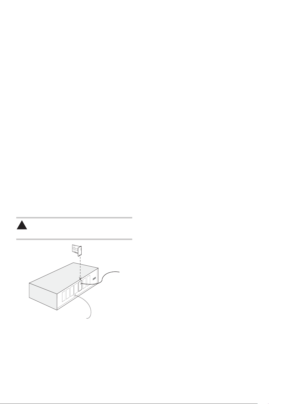
Installing a daughtercard
CAUTION: It is essential that full anti-static precautions are
taken before working within the UCC1 or UCC2 controller
enclosure or handling individual boards.
Daughtercard
UCC1 or UCC2
controller
Applicable
connection(s)
Communication link
to host computer
The following procedure is recommended for installing a daughtercard
into the UCC1 or UCC2:
1. Remove the a.c. power supply from the controller and disconnect
all cables from the CMM.
2. Remove the top panel of the unit by removing the five screws at
the top of the rear panel and the screw located at the top of each
side panel, near the front. Retain the fixing screws.
3. Select a socket on the mother board to house the daughtercard.
4. Remove (and store for possible re-use) the blanking plate from
the rear panel of the enclosure.
5. Carefully position the daughtercard so that the rear connectors
pass through the hole in the controller rear panel, but without
engaging the motherboard connector.
6. Align the daughtercard’s connector with the socket on the
motherboard.
7. Check that the rear panel top hook of the daughtercard is located
above the slot in the rear panel.
8. Press the daughtercard firmly into the socket on the motherboard
until it is seen to be fully engaged.
9. Confirm that the top hook is engaged in the rear panel. If it is not,
repeat steps 7 and 8.
10. Refit the top panel of the enclosure and secure using the fixing
screws.
11. Reconnect all cables between the controller and CMM. Switch on
the a.c. power supply.
Removing a daughtercard
Remove a daughtercard from the UCC1 or UCC2 as follows:
1. Remove the a.c. power supply from the controller and disconnect
all cables from the CMM.
2. Remove the top panel of the unit by removing the five screws at
the top of the rear panel and the screw located at the top of each
side panel, near the front. Retain the fixing screws.
3. Carefully remove the daughtercard from the connector on the
motherboard, taking care to disengage the top hook from the rear
panel.
4. Refit the blanking plate in the rear panel of the enclosure.
5. Refit the top panel of the enclosure and secure using the fixing
screws.
6. Reconnect all cables between the controller and CMM. Switch on
the a.c. power supply.
 Loading...