

Page 1

Installation guide
H-1000-5220-02-B
UCC daughtercards
Page 2

© 2003 - 2006 Renishaw plc. All rights reserved.
This document may not be copied or reproduced in whole or in
part, or transferred to any other media or language, by any means,
without the prior written permission of Renishaw.
The publication of material within this document does not imply
freedom from the patent rights of Renishaw plc.
Disclaimer
Considerable effort has been made to ensure that the contents of
this document are free from inaccuracies and omissions. However,
Renishaw makes no warranties with respect to the contents of
this document and specifi cally disclaims any implied warranties.
Renishaw reserves the right to make changes to this document
and to the product described herein without obligation to notify any
person of such changes.
Trademarks
RENISHAW® and the probe emblem used in the RENISHAW logo
are registered trademarks of Renishaw plc in the UK and other
countries.
apply innovation is a trademark of Renishaw plc.
All brand names and product names used in this document are
trade names, service marks, trademarks, or registered trademarks
of their respective owners.
Renishaw part no: H-1000-5220-02-B
Issued: 05 2006
Page 3

UCC daughtercard
installation guide
Page 4

2 Care of equipment
Care of equipment
Renishaw probes and associated systems are precision tools used for obtaining precise
measurements and must therefore be treated with care.
Changes to Renishaw products
Renishaw reserves the right to improve, change or modify its hardware or software without
incurring any obligations to make changes to Renishaw equipment previously sold.
Warranty
Renishaw plc warrants its equipment for a limited period (as set out in our Standard Terms and
Conditions of Sale) provided that it is installed exactly as defined in associated Renishaw
documentation.
Prior consent must be obtained from Renishaw if non-Renishaw equipment (e.g. interfaces and/or
cabling) is to be used or substituted. Failure to comply with this will invalidate the Renishaw
warranty.
Claims under warranty must be made from authorised service centres only, which may be advised
by the supplier or distributor.
Trade marks
Windows 98, Windows XP, Windows 2000 and Windows NT are registered tradenames of the
Microsoft Corporation.
All trademarks and tradenames are acknowledged
References and associated documents
It is recommended that the following documentation is referenced to when installing the UCC.
Renishaw documents
Relevant documentation supplied on Renishaw UCC software CD.
Document number Title
H-1000-5056 UCC1 installation guide
H-1000-5057 UCC controller programmer’s guide
H-1000-5058 UCC Renicis user’s guide
H-1000-5227 UCC servo tuning user’s guide
H-1000-5223 UCC2 installation guide
Page 5

Contents 3
Contents
1 Introduction.............................................................................................................................................. 6
2 Daughtercards ......................................................................................................................................... 7
2.1 Installation in the UCC................................................................................................................... 8
2.2 Removal of a daughtercard ........................................................................................................... 9
3 PHC1050 daughtercard......................................................................................................................... 10
3.1 Introduction.................................................................................................................................. 10
3.2 Connector and pin outs ............................................................................................................... 11
3.2.1 Head connector.............................................................................................................11
3.2.2 HCU connector .............................................................................................................11
3.3 Configuration options .................................................................................................................. 12
3.3.1 Two wire probe configuration........................................................................................12
3.3.2 Multiwire probe configuration ........................................................................................13
3.4 Operating overview ..................................................................................................................... 14
3.4.1 Communication with the PHC1050...............................................................................14
3.4.2 Configuring the PHC1050 board...................................................................................14
3.4.3 Power-up sequence ......................................................................................................15
3.4.4 Probe head operation ...................................................................................................15
4 PICS/RS232 daughtercard .................................................................................................................... 16
4.1 Introduction.................................................................................................................................. 16
4.2 Connector and pin outs ............................................................................................................... 16
4.2.1 PICS A connector .........................................................................................................16
4.2.2 RS232 connectors (9-way D-type plug) ........................................................................17
4.3 Configuration options .................................................................................................................. 18
4.3.1 Connecting an external PHC10 to the UCC..................................................................18
4.3.2 Connecting an ACC2-2 to the UCC ..............................................................................19
4.3.3 RS232 communication cable ........................................................................................20
4.4 Operating overview ..................................................................................................................... 20
4.4.1 PICS A port ...................................................................................................................20
4.4.2 RS232 channel 2 ..........................................................................................................20
4.4.3 RS232 channel 3 ..........................................................................................................21
5 Joystick interface daughtercard (JI card)............................................................................................... 22
5.1 Introduction.................................................................................................................................. 22
5.2 Connector and pin outs ............................................................................................................... 22
5.2.1 Joystick connector ........................................................................................................23
5.2.2 Emergency stop connector ...........................................................................................24
5.3 Configuration options .................................................................................................................. 25
5.3.1 Minimum recommended installation wiring ...................................................................25
5.3.2 Emergency stop signal..................................................................................................26
5.3.3 Analogue input signal....................................................................................................27
5.3.4 input circuit...................................................................................................................27
5.3.5 Binary output circuit ......................................................................................................28
Page 6

4 Contents
5.4 Operating overview...................................................................................................................... 28
5.4.1 Method of operation ..................................................................................................... 28
5.4.2 Initialising the JI card.................................................................................................... 29
5.4.3 Joystick modes.............................................................................................................29
5.4.4 Joystick type selection ................................................................................................. 30
5.4.5 Enable joystick ............................................................................................................. 30
5.4.6 Functionality in DCC mode .......................................................................................... 31
5.4.7 Functionality in joystick mode ...................................................................................... 32
5.4.8 Changing modes.......................................................................................................... 32
5.4.9 Moving and touching.................................................................................................... 32
5.4.10 Recording points ..........................................................................................................33
5.4.11 Probe damping.............................................................................................................33
5.4.12 Joystick orientation....................................................................................................... 34
6 MCU1 daughtercard .............................................................................................................................. 36
6.1 Introduction.................................................................................................................................. 36
6.2 Connector and pin outs ............................................................................................................... 36
6.2.1 MCU connector ............................................................................................................ 37
6.2.2 Emergency stop connector .......................................................................................... 37
6.3 Configuration options................................................................................................................... 38
6.3.1 Emergency stop signal................................................................................................. 38
6.4 Operating overview...................................................................................................................... 38
6.4.1 Method of operation ..................................................................................................... 38
7 SP25M daughtercard............................................................................................................................. 39
7.1 Introduction.................................................................................................................................. 39
7.2 Connectors and pin outs.............................................................................................................. 39
7.2.1 Analogue probe connector........................................................................................... 39
7.3 Operating overview...................................................................................................................... 40
7.3.1 Method of operation ..................................................................................................... 40
8 SP80 daughtercard................................................................................................................................ 41
8.1 Introduction.................................................................................................................................. 41
8.2 Connector and pin outs ............................................................................................................... 41
8.2.1 SP80 connector............................................................................................................ 41
8.3 Operating overview...................................................................................................................... 42
9 Additional I/O daughtercard ................................................................................................................... 43
9.1 Introduction.................................................................................................................................. 43
9.2 Connector and pin outs ............................................................................................................... 43
9.2.1 Additional I/O connector............................................................................................... 43
9.3 Operating overview...................................................................................................................... 44
9.3.1 Software integration ..................................................................................................... 44
9.3.2 Electrical integration.....................................................................................................45
10 Temperature sensor daughtercard ........................................................................................................ 46
10.1 Introduction.................................................................................................................................. 46
10.2 Connector and pin outs ............................................................................................................... 46
Page 7

Contents 5
10.2.1 44-way connector..........................................................................................................47
10.3 Operating overview ..................................................................................................................... 47
10.3.1 Software integration ......................................................................................................48
10.3.2 Electrical integration......................................................................................................49
11 Additional axis daughtercard ................................................................................................................. 50
11.1 Introduction.................................................................................................................................. 50
11.2 Connector and pin outs ............................................................................................................... 50
11.2.1 Scale connector ............................................................................................................51
11.2.2 Table / axis connector...................................................................................................52
11.2.3 Emergency stop connector ...........................................................................................54
11.3 Configuration options .................................................................................................................. 55
11.3.1 Daughtercard channel setting .......................................................................................55
11.3.2 Emergency stop signal..................................................................................................56
12 PHS daughtercard ................................................................................................................................. 57
12.1 Introduction.................................................................................................................................. 57
12.2 Connector and pin outs ............................................................................................................... 57
12.2.1 PHS connector..............................................................................................................57
12.3 Configuration options .................................................................................................................. 58
12.3.1 PHS power PCB settings ..............................................................................................58
12.4 PHS card installation ................................................................................................................... 58
12.4.1 Power connection .........................................................................................................58
12.4.2 PHS control PCB settings .............................................................................................60
13 Revision history ..................................................................................................................................... 61
13.1 What’s new in release 01-A......................................................................................................... 61
13.2 What’s new in release 02-A......................................................................................................... 61
13.3 What’s new in release 02-B......................................................................................................... 61
Page 8
6 Introduction
1 Introduction
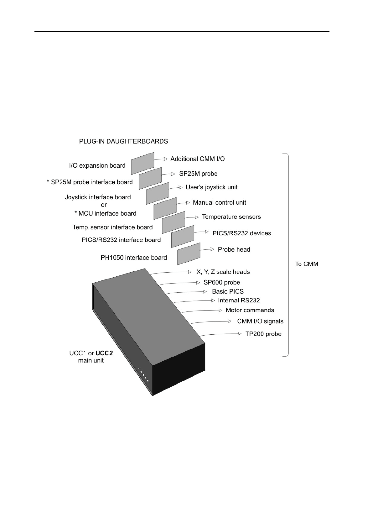
The purpose of this chapter is to outline the capabilities of the various UCC daughtercards and the
generic installation instructions to fit these cards into the UCC1 or UCC2 units.
There are a range of UCC daughtercards available, each offering additional capabilities to the
standard UCC1 or UCC2 product. For specific details on each card please refer to the respective
section within this installation guide.
* Not compatible with UCC2 system as these cards have been integrated into the UCC2 design
Page 9

Daughtercards 7
2 Daughtercards
Listed below are the range of UCC1 daughtercards available with a brief explanation of their
capabilities:
Daughtercard Description
PHC1050 Permits connection of a PH10 motorised probe head to
the UCC controller.
PICS/RS232 Adds two RS232 communication ports to the UCC, and
includes a PICS compliant connector.
JI Permits the connection of a third party analogue joystick
to the UCC controller.
MCU1 Permits the connection of the Renishaw MCU1 joystick to
the UCC controller.
SP25M Permits the UCC controller to accept the SP25M probe
signals.
SP80 Permits the UCC controller to accept the SP80 probe
signals.
Additional input/output Increases the number of uncommitted input and output
signals available to the UCC controller.
Temperature sensor Permits the UCC to accept and interface up to 24
temperature sensors.
Additional axis Permits the UCC to control an additional machine axis or
a rotary table. Multiple cards can be installed within a
UCC system.
PHS Permits the PHS probe head to be integrated into the
UCC2 controller.
Refer to
section
3
4
5
6
7
8
9
10
11
12
Page 10

8 Daughtercards
2.1 Installation in the UCC
CAUTION: It is essential that full anti-static precautions are taken before working within
!
the UCC1 or UCC2 controllers enclosure or handling individual boards.
CAUTION: Removing the top panel of the UCC enclosure will give access to the mains
!
driver power supply (PSU). The PSU is further protected by a metal cover. This
protective cover MUST NOT BE REMOVED as it would expose hazardous voltages.
The following procedure is recommended for installing a daughtercard:
1. Remove the ac power supply from the UCC1 or UCC2 and move the unit so you have clear
access to the top and rear of the enclosure, it may be necessary to disconnect some of the
other cables to achieve this.
2. Remove the top panel of the UCC1 or UCC2 enclosure by removing the screws at the top
of the rear panel and the screw located at the top of each side panel, near the front. Retain
the fixing screws.
3. Select a socket on the motherboard to house the daughtercard (all sockets are compatible).
NOTE: Install long daughtercards and daughtercards with appreciable heat dissipation towards
the power supply end of the UCC1 or UCC2.
If the PHS daughtercard is to be installed into the UCC2 it must be fitted into the fourth socket
from the power supply.
4. Remove (and store for possible re-use) the appropriate blanking plate from the rear panel of
the enclosure.
5. Carefully position the daughtercard so that the rear connectors pass through the hole in the
controller rear panel, but without engaging the motherboard connector.
6. Align the daughtercard plug with the socket on the motherboard.
7. Check that the rear panel hook of the daughtercard is located above the slot in the rear
panel.
8. Press the daughtercard firmly into the socket on the motherboard until it is seen to be fully
engaged.
9. Confirm that the top hook is engaged in the rear panel, if it is not then repeat steps 7 and 8.
Page 11

Daughtercards 9
10. If a PHS daughtercard is being installed please refer to section 12.4 at this stage of the
process.
11. Refit the top panel of the enclosure and secure using the fixing screws.
12. Reconnect all disconnected cables between the UCC1 or UCC2 and the CMM and then the
mains cable. Switch on the ac supply.
2.2 Removal of a daughtercard
The following procedure is recommended for removal of a daughtercard from the UCC1 or UCC2.
CAUTION: It is essential that full anti-static precautions are taken before working within
!
the UCC1 or UCC2 controller enclosure or handling individual boards.
1. Remove the ac power supply from the UCC1 or UCC2 and move the unit so you have clear
access to the top and rear of the enclosure, it may be necessary to disconnect some of the
other cables to achieve this.
2. Remove the top panel of the enclosure by removing the five screws at the top of the rear
panel and the screw located at the top of each side panel, near the front. Retain the fixing
screws.
3. Carefully remove the daughtercard from the socket on the motherboard, taking care to
disengage the top hook from the rear panel.
4. Refit the blanking plate in the rear panel of the enclosure
5. Refit the top panel of the enclosure and secure using the fixing screws.
6. Reconnect all disconnected cables between the UCC1 or UCC2 and the CMM and then the
mains cable. Switch on the ac supply.
Page 12

10 PHC1050 daughtercard
3 PHC1050 daughtercard
NOTE: This daughtercard is suitable for use in both UCC1 and UCC2 controllers.
3.1 Introduction
The PHC1050 interface board is one of a range of plug-in daughtercards for Renishaw CMM
controllers. It provides a simple interface between the PH10 probe head and the metrology frontend software using no external hardware and with minimal cabling and connectors.
Provision is made for a probe head hand controller (HCU1), although this is not necessary if an
MCU1 joystick is fitted to the system.
The PHC1050 is an internal option which enables the UCC1 or UCC2 to offer all the functions of
the Renishaw PHC10-2 probe head controller.
The PHC1050 supports the basic and extended command set from the front-end software in their
original format, ensuring interchangeability and an easy upgrade path. The commands are
transmitted via the link from the host PC to the UCC controller. Probe signals are handled directly
by the UCC1 or UCC2.
Page 13

PHC1050 daughtercard 11
3.2 Connector and pin outs
On the rear panel of the PHC1050 are two connectors:
• The connection to the PH10 head, via the 15-way D-type plug labelled HEAD
• The optional connection to the HCU1, via the 9-way D-type socket labelled HCU
PHC1050
HCU
HEAD
efg
3.2.1 Head connector
The head connector is a 15-way D-type socket with the signals as detailed in the table below, for
further details on these signals please refer to the PH10 installation guide (Renishaw part number
H-1000-5071).
Pin number Function
1 Ground sense
2 Head present
3 A axis feedback
40 V
5 Motor probe switch
6 12 V reference
7 B axis motor / probe contact
8 LED and datum
9 Not connected
10 Locking motor drive
11 A axis motor
12 A axis motor
13 Not connected
14 B axis feedback
15 B axis motor / probe contact
Shell Screen
3.2.2 HCU connector
The HCU connector is a 9-way D-type socket with the necessary signals to connect directly to the
HCU1 handbox, for further information please refer to the HCU1 user’s guide (Renishaw part
number H-1000-5016).
Page 14
12 PHC1050 daughtercard
3.3 Configuration options
3.3.1 Two wire probe configuration
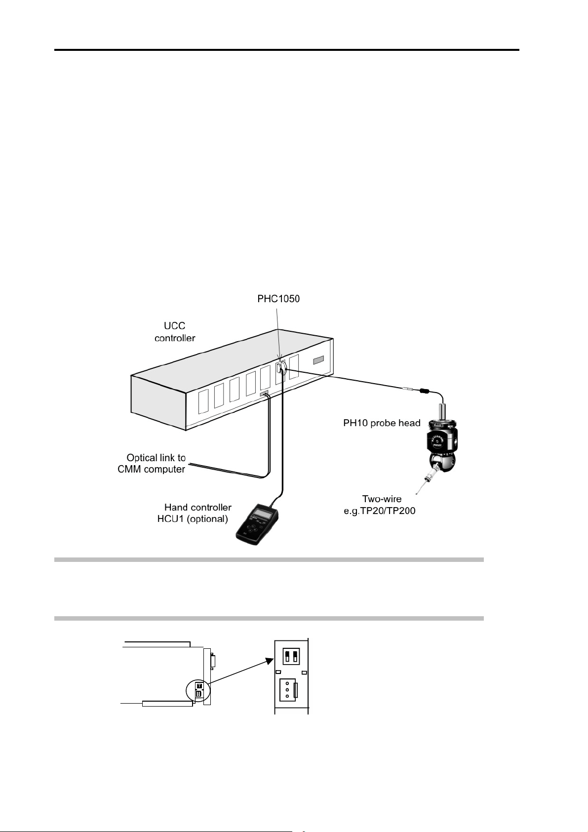
The diagram below shows a typical wiring arrangement for a two-wire touch trigger probe system
incorporating a PH10 motorised probe head.
The PHC1050 daughtercard may be fitted into any of the available slots in the UCC.
• The cable from the probe head should be connected to the 15-way D-type plug marked 'HEAD'
on the PHC1050 rear panel. The probe signals within this cable are connected automatically to
the UCC motherboard for interfacing.
• The cable from the hand control unit (if fitted) should be connected to the 9-way D-type socket.
NOTE: Ensure that the configuration switches on the PHC1050 card are both set to ‘ON’ UP
position as shown in diagram below (factory default). This routes the probe signal through the card
to the internal interface.
PHC1050
card
Page 15
PHC1050 daughtercard 13
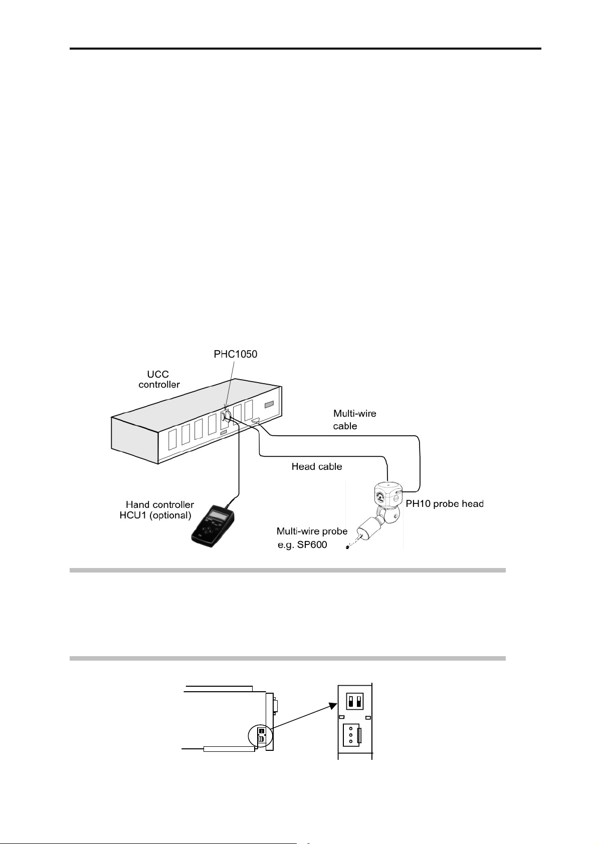
3.3.2 Multiwire probe configuration
The diagram below shows a typical wiring arrangement for a system incorporating an analogue
scanning probe (SP600) and two-wire touch trigger probe incorporating a PH10 motorised probe
head.
The head cable links the probe head to the PH1050 daughtercard and the multiwire cable
connects directly to the analogue probe socket on the rear panel of the controller, to permit
interfacing of TP2/6/20, TP200 and SP600 probes (and SP25 on UCC2).
The PHC1050 daughtercard may be fitted into any of the available slots in the UCC.
• The cable from the probe head should be connected to the 15-way D-type plug marked 'HEAD'
on the PHC1050 rear panel. The probe signals within this cable are connected automatically to
the UCC motherboard for interfacing.
• The cable from the hand control unit (if fitted) should be connected to the 9-way D-type socket
marked 'HCU' on the PHC1050 rear panel.
NOTE: Ensure that the configuration switches on the PHC1050 Card are both set to ‘OFF’
DOWN position as shown in diagram below. This routes only the head signals through the
PHC1050 card.
Failure to configure the switches as detailed can result in illegal triggers when using the system.
PHC1050
card
Page 16

14 PHC1050 daughtercard
3.4 Operating overview
The PHC1050 must be installed within the UCC and connected to the PH10 motorised probe head
before the controller is powered up.
When the UCC software is downloaded, it searches the internal bus for daughtercards and will
detect the presence of the PHC1050 daughtercard.
NOTE: If no PHC1050 card is found and a PICS/RS232 daughtercard is identified on the UCC
internal bus, all PHC commands will be routed to the PICS/RS232 daughtercard for use by an
external motorised head controller.
However, if no PHC1050 or PICS/RS232 daughtercards are found then the system will return an
error if any motorised probe head commands are sent to the UCC1 controller.
The metrology front-end software may then configure the PHC1050 using UCC command 340
(PHC1050 initialise), refer to following section and the UCC command set (Renishaw part number
H-1000-5222) for more information.
3.4.1 Communication with the PHC1050
The CMM metrology front-end program can communicate with the probe head in a similar manner
to that used in the RS232C link with an external PHC system.
• The application selects commands from either the basic command set or the RECS (Renishaw
extended command set).
• The command is sent to the controller using UCC command number 336 (Write to PHC10), to
transfer the data.
• The UCC will automatically direct the command to the PHC1050 daughtercard. (If this is not
fitted refer to note above)
• Any reply is read by using the UCC command number 337 (Read from PHC10), referring to the
status flags as described in the UCC command set document.
3.4.2 Configuring the PHC1050 board
The only hardware configuration on the PHC1050 board is that for probe type selection, please
refer to section 3.3 for details.
Other configuration options for the PHC1050 daughtercard are software configurable using UCC1
command 340 (PHC1050 initialise). Refer to the UCC command set (Renishaw part number
H-1000-5222) for further details.
Following receipt of command 340 (PHC1050 initialise) the UCC system will enable/disable the
applicable options.
Page 17

PHC1050 daughtercard 15
NOTE: As part of this process the servo motors, if engaged, will be disengaged and the
PHC1050 will be reset to its default manual or automatic mode.
The default configuration mode of the PHC1050 depends on whether a hand control unit is fitted
(manual mode) or not fitted (automatic mode). This mode can be changed by the use of command
336 (Write to PHC10).
3.4.3 Power-up sequence
The PHC1050 (or PICS/RS232) daughtercard is powered from the internal UCC power supply,
provided that all components are connected before power-up, they will initialise correctly.
Plugging or unplugging a motorised probe head with the system live is described in the basic
command set programming manual (H-1000-5075). The same process should be used with a
PHC1050.
3.4.4 Probe head operation
For programming probe head operation, refer to the basic command set programming manual
(Renishaw part number H-1000-5075), the same flow charts and programming techniques apply.
Any references in the basic command set programming manual with regards to RS232
communications should be replaced by the UCC commands 336 (Write to PHC10) and 337 (Read
from PHC10) to send data over the link to the PHC1050 or PICS/RS232 daughtercard via the
UCC controller.
NOTE: None of the IEEE488 communications protocols are supported by the UCC system.
Page 18
16 PICS/RS232 daughtercard
4 PICS/RS232 daughtercard
NOTE: This daughtercard is suitable for use in both UCC1 and UCC2 controllers.
4.1 Introduction
The UCC supports a PICS B (IN) and an RS232 port (channel 1) for use by Renishaw probes and
peripherals. By including this option card into the UCC system two additional RS232 ports and a
PICS A (OUT) port are incorporated, allowing the basic measuring system to be enhanced with
alternative probes and/or added peripherals.
4.2 Connector and pin outs
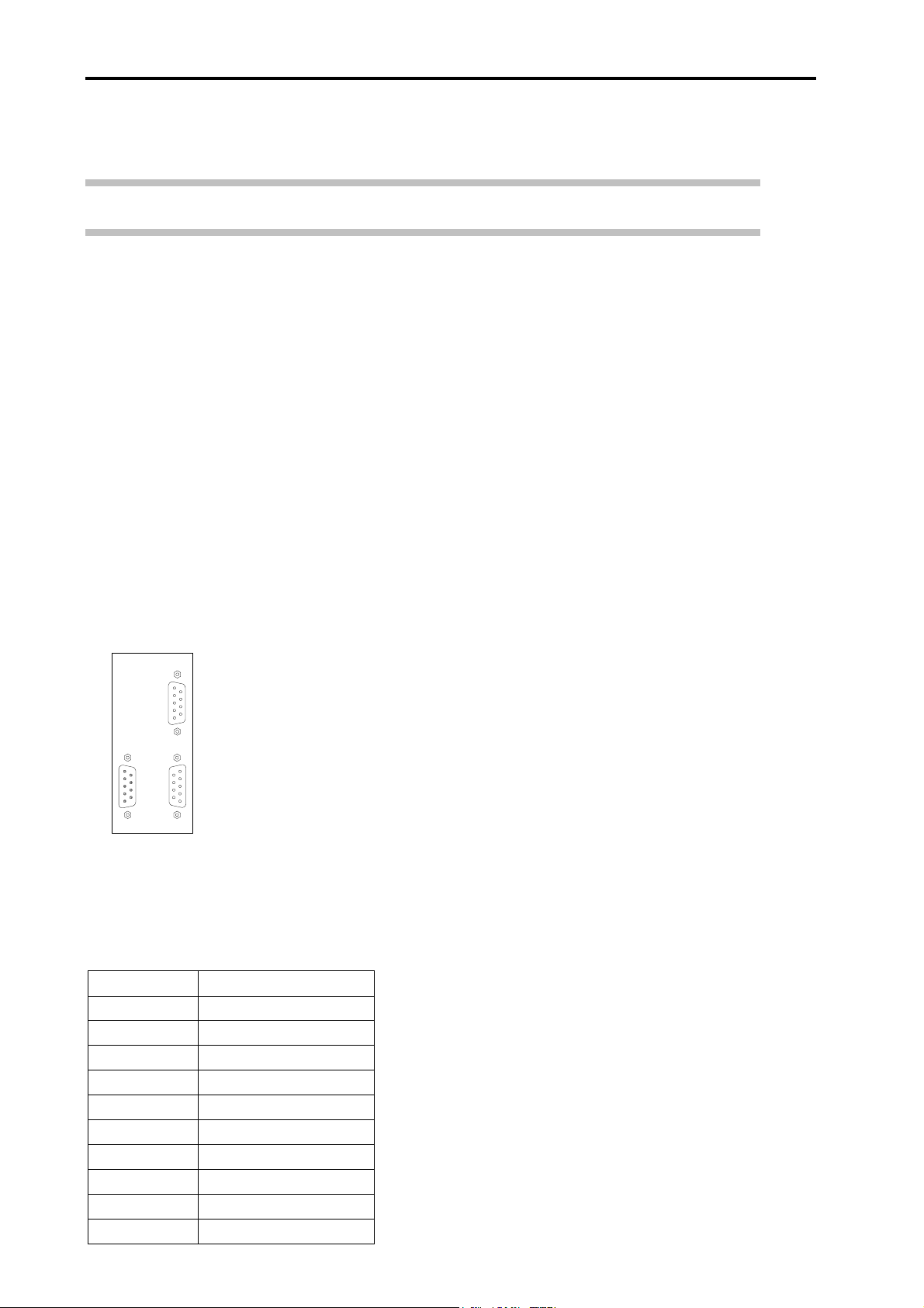
On the rear panel of the PICS/RS232 daughtercard there are three connectors these are:
• PICS A
• RS232 channel 2
• RS232 channel 3
PICS / RS232
RS232 CH 2
efg
PICS A
RS232 CH 3
4.2.1 PICS A connector
The PICS A connector is a 9-way D-type socket with the signals as detailed in the table below.
This connection conforms to the Renishaw PICS standard and all signals are active low. Refer to
PICS installation guide (Renishaw part number H-1000-5000) for further information.
Pin number Function
1STOP
2 PPOFF
30V
4 Reserved
5 SYNC
6HALT
7PDAMP
8 LED OFF (out)
9
Shell Screen
Page 19

PICS/RS232 daughtercard 17
4.2.2 RS232 connectors (9-way D-type plug)
RS232 CH2 (RS232 channel 2) and RS232 CH3 (RS232 channel 3) connectors have the same
pin-outs as detailed in the table below.
Pin number Function
1 Not connected
2 RX data
3 TX data
4DTR
5 Signal ground
6 Not connected
7RTS
8CTS
9 Not connected
Shell Screen
NOTE: The communication protocols for these connectors are fixed and can not be changed.
Refer to section 4.4.2 and 4.4.3 for details.
Page 20
18 PICS/RS232 daughtercard
4.3 Configuration options
4.3.1 Connecting an external PHC10 to the UCC
The figure below shows a UCC system fitted with the PICS/RS22 daughtercard, an external
PHC10-2 and an external Renishaw interface (OPI6).
In this case it is necessary to use both the PICS A and the RS232 channel 3 connectors on the
PICS/RS232 daughtercard.
PICS / RS232
RS232 CH 2
efg
PICS A
RS232 CH 3
The recommended dip switch settings for the PHC10-2 unit shown in this configuration are given
in the table below
NOTE: If the RECS command set is being used then dip switch should be in the up position.
123456789101112131415161718
UP X X XXXX
DOWN X XXXXXXXXXXX
The RS232 communication cable between the PICS RS232 daughtercard and the PHC10-2
shown in this configuration is not available from Renishaw, the connections details for this cable
are as detailed in section 0.
Page 21

PICS/RS232 daughtercard 19
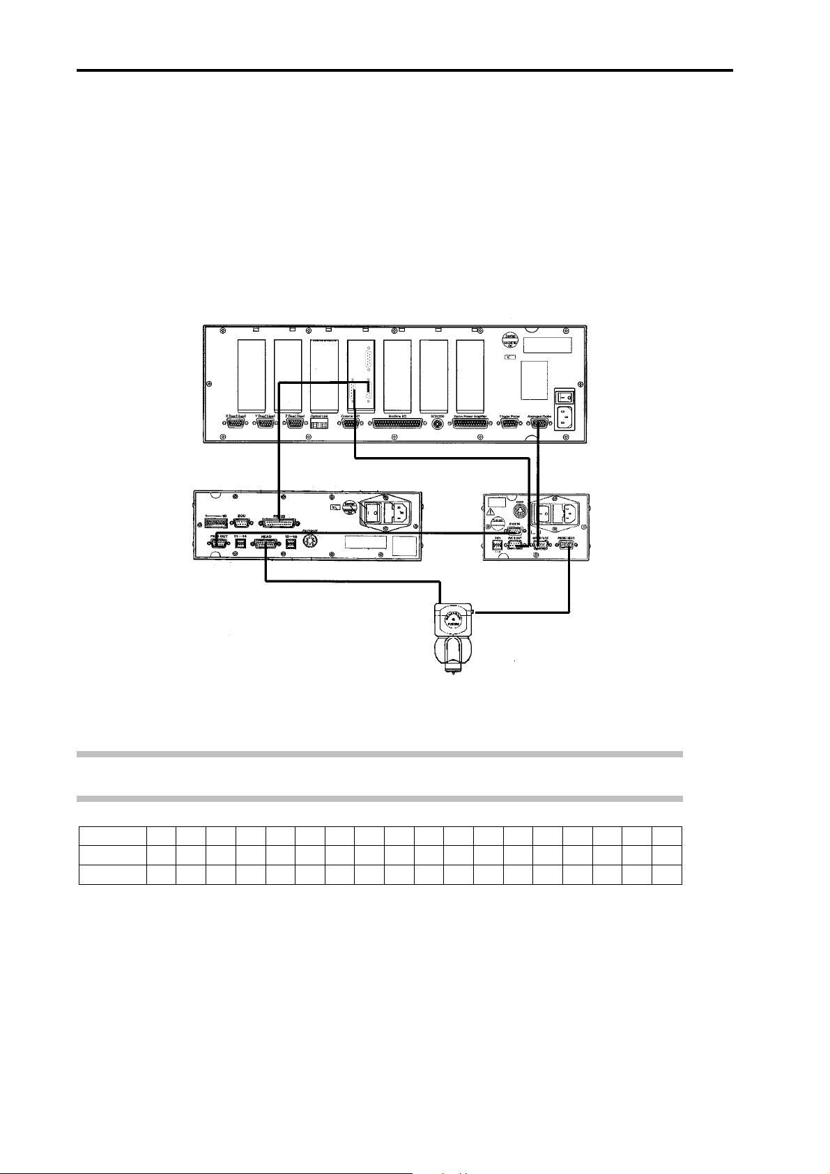
4.3.2 Connecting an ACC2-2 to the UCC
The figure below shows a UCC system fitted with the PICS/RS22 daughtercard, an external
PHC10-2, an ACC2-2 and an external Renishaw interface (OPI6).
In this case it is necessary to use all three of the connectors on the PICS/RS232 daughtercard.
PICS / RS232
RS232 CH 2
efg
PICS A
RS232 CH 3
In this connection scheme it is necessary to configure the PHC10-2 as detailed in section 4.3.1, it
is also necessary to manufacture two RS232 cables as detailed in section 4.3.3 to connect the
ACC2-2 and the PHC10-2 to the PICS/RS232 daughtercard.
NOTE: If only an external ACC2-2 is to be used without the external interface and PHC10-2
controller then it is necessary to terminate the PICs signals used by the ACC2-2 controller. This is
done by placing a 100K resistor between pins 1 & 6 and 1 & 5 on the PIC IN connector of the
ACC2-2 unit.
The recommended dip switch settings for the ACC2-2 unit shown in this configuration are given in
the table below:
1 2 3 4 5 6 7 8 9 10 11 12 A B
UP X X X X
DOWN X XXXXX XX XX
Page 22

20 PICS/RS232 daughtercard
4.3.3 RS232 communication cable
The RS232 communication cable between the PICS/RS232 daughtercard and either the ACC2-2
or the PHC10-2 product is a standard null modem cable, the connection details are shown below:
PICS/RS232 CH3
9-way D-socket
1
2
3
4
5
6
7
84
4.4 Operating overview
4.4.1 PICS A port
PHC10-2
25-way D-socket
20
2
3
6
7
8
5
This port will be used for the control of external Renishaw interface products (e.g. PI 7-2, OPI6,
etc.) as described in the appropriate UCC installation manual (Renishaw part number
H-1000-5056 for UCC1, H-1000-5223 for UCC2) and the installation guide for the peripherals
concerned.
The signals produced by the PICS interface circuits in the board are used internally by the UCC
controller but may be examined or modified by using the appropriate UCC commands 280 (Read
from PICS port) and command 325 (Write to PICS port).
NOTE: Installing the PICS/RS232 daughtercard will disable the PICS “B” (IN) port on the UCC.
This is no longer required, since the interface board connects internally to the controller.
4.4.2 RS232 channel 2
This connector handles the serial data link to such Renishaw products as the ACC2-2 or any other
compatible external equipment connected to this communication port.
More detailed information about the ACC2-2 software routines is available in the installation and
programmers guide (Renishaw part number H-1000-6010).
To read or write to this communication port command 338 (write to ACC), and command 339
(read from ACC), please refer to the UCC command set document (Renishaw part number
H-1000-5222) for further information.
Page 23

PICS/RS232 daughtercard 21
The serial communications parameters used by this port are not configurable and set as detailed
below:
Baud rate 9600
Data 7 bits
Parity even
Stop 1 bit
The user should ensure that the device connected to this port uses the same settings.
4.4.3 RS232 channel 3
This connector handles the serial data link to Renishaw products such as the PHC10-2 or any
other compatible external equipment connected to the communication port.
More detailed information about the PHC10-2 software routines is available in the programmers
guide (H-1000-5075).
To read or write to this communication port command 336 (Write to PHC), and command 337
(read from PHC), please refer to the UCC command set document (Renishaw part number
H-1000-5222) for further information.
The serial communications parameters used by this port are not configurable and set as detailed
below:
Baud rate 9600
Data 8 bits
Parity none
Stop 2 bit
The user should ensure that the device connected to this port uses the same settings.
Page 24

22 Joystick interface daughtercard
5 Joystick interface daughtercard (JI card)
NOTE: This daughtercard is suitable for use in both UCC1 and UCC2 controllers.
5.1 Introduction
The joystick interface daughtercard (referred to in this document as the ‘JI card’) is one in a range
of plug-in daughtercards for the Renishaw UCC universal CMM controllers.
For the UCC1 kit (A-1333-0003) a JI card is provided as part of the kit. UCC1 kit (A-1333-0006)
provides an MCU1 (Renishaw joystick) interface.
The UCC2 controller has the MCU1 interface integrated into the motherboard and no other
interfaces are fitted. If a JI card is required then it must be ordered as a separate item
(A-1333-0020).
The JI card provides a flexible interface between the UCC controller and many different types of
OEM joystick control units. It has provision for analogue signals from the joystick unit. Multiple
switch and indicator signals can be accepted or provided.
The JI card is configured by commands from the metrology front-end software, via the UCC
controller, to select the required functions from the available range.
Physically, the device consists of a single printed circuit board with a connector to suit the
controller's internal bus sockets. The board has a metal end plate for fixing to the rear panel of a
UCC1 or UCC2 controller. Attached to the metal panel is a 37-way D-type plug, to connect to the
user's joystick unit, and a 2-way socket dedicated to the wiring from any emergency stop switch
on the joystick unit.
Electrically, the interface board carries an embedded processor and the required circuits to
process analogue joystick signals and to handle the two-way communications with the controller.
The JI board is powered by the UCC controller and will provide d.c. power to the joystick unit if
required.
5.2 Connector and pin outs
On the rear panel of the JI daughtercard are two connectors:
• the connection to the joystick unit, via a 37-way D-type connector, labelled joystick
• the connection to the CMMs emergency stop system, via a dedicated 2-way connector,
labelled EMERGENCY STOP
Page 25

Joystick interface daughtercard 23
5.2.1 Joystick connector
The joystick connector is a 37-way D-type plug with the signals as detailed in the table below:
Pin
number
1 +5 V supply from JI - 2 Digital ground - - 3 +12 Vdc supply from JI - 4 -12 Vdc supply from JI - 5 Analogue ground - - 6 +24 Vdc supply from JI - 7 24V return to JI - 8 Emergency stop A to JI - 5.3.2
9 Emergency stop B to JI - 5.3.2
10 Analogue axis, X to JI + signal gives + move* 5.3.3
11 Analogue axis, Y to JI + signal gives + move* 5.3.3
12 Analogue axis, Z to JI + signal gives + move* 5.3.3
13 Analogue axis, W to JI - 5.3.3
14
15 Dead man's handle to JI <1V = JI operational 5.3.4
16 X axis lock to JI <1V = axis locked 5.3.4
17 Y axis lock to JI <1V = axis locked 5.3.4
18 Z axis lock to JI <1V = axis locked 5.3.4
19** W axis lock to JI - 5.3.4
20 Probe enable to JI <1V = probe disabled 5.3.4
21 Fast/slow to JI <1V = Fast 5.3.4
22 Record point to JI <1V = record point 5.3.4
23 Cancel last point to JI <1V = cancel last point 5.3.4
24 Reset TP200 probe to JI <1V = reset TP200 5.3.4
25 Reserved 26 Reserved 27 Axis swap to JI 28 Axis swap to JI 29 Joystick/DCC to JI <1V = DCC mode 5.3.4
30 X axis lock indicator from JI <1V = axis not locked 5.3.5
31 Y axis lock indicator from JI <1V = axis not locked 5.3.5
32 Z axis lock indicator from JI <1V = axis not locked 5.3.5
33** W axis lock indicator from JI - 5.3.5
34 Probe enabled indicator from JI <1V = probe is enabled 5.3.5
35 Beep control from JI <1V = beep sounding 5.3.5
36 Near max. speed from JI <1V = near max speed 5.3.5
37
Shell Shell and screen - - -
Function (primary)
Analogue speed
override
Servo engaged
indicator
Signal
direction
to JI +12V = FS, -12v = stop 5.3.3
from JI <1V = servo disengaged 5.3.5
Signal
effect
Schematic
* Assuming an ISO 841 right-handed co-ordinate system
** See also secondary built-in functions
Page 26

24 Joystick interface daughtercard
5.2.2 Emergency stop connector
The emergency stop connector is a two pin Lemo connector that is connected directly to pins 8
and 9 of the 37-way D-type plug. These pins should be connected into the CMM’s emergency
stop system if an emergency stop button is mounted on the joystick.
Pin number Function
1 ESTOP A
2 ESTOP B
Shell Screen
Page 27

Joystick interface daughtercard 25
5.3 Configuration options
5.3.1 Minimum recommended installation wiring
The figure below shows the recommended minimum installation wiring scheme for connecting a
joystick to the JI card.
Page 28

26 Joystick interface daughtercard
5.3.2 Emergency stop signal
The figure below shows the EMERGENCY STOP signal routing through the JI card.
NOTE: The emergency stop signal is not connected to any internal circuits within the UCC1 or
UCC2, the emergency stop signal is routed directly from the 37-way D-type connector to the
emergency stop connector on the rear of the card.
For recommended installation wiring please refer to the UCC1 or UCC2 installation guides
(Renishaw part numbers H-1000-5056 or H-1000-5223 respectively).
Page 29

Joystick interface daughtercard 27
5.3.3 Analogue input signal
The figure below gives the analogue input circuit that is incorporated into the JI card. These are
all transient-protected and standardised.
There are connections for four analogue axis signals and one analogue speed signal from the
joystick unit to the UCC JI card.
The input voltage range is ±12 V nominal, ±15 V maximum. Positive inputs should produce
machine movements in a positive direction.
5.3.4 Binary input circuit
The figure below gives the binary input circuit that is incorporated into the JI card, which are all
transient-protected and standardised.
The input voltage range is ±12 V nominal, ±15 V maximum. The active state for this connection is
with the input connected to pin 2.
Page 30

28 Joystick interface daughtercard
5.3.5 Binary output circuit
The figure below gives the binary output circuit that is incorporated into the JI card. These are all
standardised.
The active state for this connection is with the transistor conducting and the limits for this
connection are listed below.
Maximum output current = 100 mA
Output voltage @ 100 mA = 1.1 volts max.
5.4 Operating overview
5.4.1 Method of operation
The JI board CPU scans all inputs from the joystick unit, the analogue signals are processed to
give suitable velocity commands for the servo system and when information is requested by the
controller, these velocity commands and other input signals are returned to it.
The controller can also send instructions to the JI board to change the states of the outputs going
to the joystick unit, e.g. to turn indicators on or off.
There is provision for up to 19 user inputs or outputs from the joystick unit which can be
configured as simple I/O to and from the user’s PC, or as controls for many built-in functions.
Page 31

Joystick interface daughtercard 29
5.4.2 Initialising the JI card
After powering up the UCC1 or UCC2 controller, the JI card must be brought into operation by the
following three actions:
• The JI card must be selected by setting Joystick type = 1 in the command 256 (Machine
configuration).
NOTE: This action will prevent the PC command 320 (Enter velocity demand) from working, since
the joystick will now provide this function.
• The JI card should also be configured to provide the characteristics required for the front-end
software application. Like most other parts of the UCC1 or UCC2 system, the JI board can be
used with all its parameters as their default settings, in which case no configuration is required.
Otherwise command 396 (Joystick configuration) should be sent to the controller. The board
can be configured before or after it has been selected.
• Finally, the JI card should be enabled using the command 397 (Joystick enable) command.
5.4.3 Joystick modes
When a CMM system is fitted with a joystick unit and a joystick daughtercard, these must be
suitably commissioned as described above. This will then permit the system to operate in one of
two modes: DCC mode or joystick mode.
In DCC mode the majority of the functions offered by the JI card are not active, moves can only be
initiated and controlled by commands from the front-end software.
NOTE: The emergency stop will always be available, if integrated, and the speed override
functions will be available if configured
In joystick mode the joystick(s) can be used to move the machine and all other JI card functions
are available, but no metrology front-end software controlled moves can be made.
The required mode can be selected either by a metrology front-end software command or by a
switch on the joystick unit.
Page 32

30 Joystick interface daughtercard
NOTE: The default JI card characteristics can be changed using command 396.
This command may be used to remove the need for the dead man’s handle and joystick/DCC
switch signals. In this state the joystick must be enabled as required by command 397 and
disabled again by the same command when a computer controlled move is required.
5.4.4 Joystick type selection
Command 256 (Machine configuration) sets a parameter called joystick type to 0 or 1.
If joystick type is set to 0:
• No joystick functions will be available (even beeps or uncommitted I/O)
• Command 320 (Enter velocity demand) from the PC will operate to give mouse-like
movements controlled by the PC
If Joystick type is set to 1:
• JI functions may be available, depending on the other factors (see below)
• A command 320 (Enter velocity demand) from the PC will be ignored
5.4.5 Enable joystick
To move the machine under joystick control requires the following conditions to have been met:
• The JI must be selected using command 256 as type 1, see Joystick type selection section
below
• The JI must be enabled using command 397 with enable set to 1
• The dead man’s handle switch signal to the JI from the joystick unit must be active (contacts
closed)
• The joystick/DCC switch signal to the JI from the joystick unit must be active (contacts open or
pulled high)
Even when the JI is selected and enabled, the signal from the joystick/DCC switch on the JI
affects the joystick availability.
Page 33

Joystick interface daughtercard 31
Since both the joystick/DCC switch and command 397 (Joystick enable) command from the PC
control the same things and both may be present, the truth table governing the system mode is:
Joystick/DCC switch set to
DCC
Joystick disabled by front
end software
Joystick enabled by front end
software
NOTE: If the joystick/DCC switch is not fitted to the JI card, the default state of the signal must be
wired to the joystick, on the JI connector, to allow the PC to control the mode.
Alternatively, the switch signal pin may be reconfigured (by command 396) for a secondary built-in
pin or as an uncommitted I/O pin: the PC command alone will then select the mode.
DCC mode DCC mode
DCC mode joystick mode
Joystick/DCC switch set to
joystick
5.4.6 Functionality in DCC mode
Active CMM functions when the system is in DCC mode:
Machine state
Function
JI commands
Speed override Yes - Yes No
Joystick controlled movements No - No No
Built-in JI functions Beep only - Beep only None
Probe enabled or disabled
Probe enable/disable indicator (on JI)
JI uncommitted I/O Yes - Yes None
Disengaged
or hold
All JI
commands
PC
controlled
PC
controlled
Joystick
move
Unavailable None None
-
-
Point-to-point
move
PC
controlled
PC
controlled
Scanning or
pencil*
PC
controlled
PC
controlled
Page 34

32 Joystick interface daughtercard
5.4.7 Functionality in joystick mode
Active CMM functions when the system is in joystick mode:
Machine state
Function
JI commands
Speed override No No - -
Joystick-controlled movements
Built-in JI functions All functions All functions -
Probe enabled or disabled
Probe enable/disable indicator (on JI) JI controlled JI controlled - -
JI uncommitted I/O Yes Yes - -
Disengaged
or hold
All JI
commands
Can be
started if in
hold state
Controlled by
JI switch
Joystick move
All except
Read JI
Version and
Configure
Yes - -
Controlled by
JI switch
Point-to-point
move
Point-to-point
move not
available
- -
Scanning or
No scanning
pencil*
or pencil
moves
available.
* Pencil mode applies to Cyclone class machines only.
5.4.8 Changing modes
If a change occurs due to the Enable command or the joystick/DCC switch which would move the
system from DCC mode to joystick mode, it will not take effect until the system is in a disengaged
or hold state.
If a change occurs which would move the system from joystick mode to DCC mode, it will take
effect as soon as any joystick activity has been terminated by the user and the system is in a
disengaged or hold state.
5.4.9 Moving and touching
When joystick mode is selected, the CMM can be moved by deflecting the joystick levers. The
system behaviour can be modified by the optional primary I/O functions.
In the event of a trigger, the CMM will be stopped and back away from the surface. The back-off
speeds and distances are defined as the maximum values for normal moves and touches in
command 257 (Move configuration).
After backing-off and finally stopping, the joysticks cannot move the machine until all three joystick
signals have been at 0 speed for the null wait time defined in command 396 (Joystick
configuration). The default value is 0.05 seconds.
The back-off direction is the reverse of the direction in which the stylus approached the surface.
Page 35

Joystick interface daughtercard 33
5.4.10 Recording points
It is often necessary to construct a program of moves and touches on the host for a repetitive
measuring procedure. Two of the primary built-in functions are designed to allow the user to log
chosen machine positions on the host as part of that construction.
When the user sends a Record point signal to the JI board, usually by pressing a momentary
switch on the joystick unit, the controller will store the current machine position and set a status
flag to alert the host. The flag is status byte B7, bit 1.
When next requesting position and status, the host should respond to this flag by recording the
position as a ‘way-point’ in the measuring program. Once the point has been read by the host, the
flag is set to zero.
If the user sends a Cancel last point signal to the JI board, usually by pressing a momentary
switch on the joystick unit, the controller will check that the last recorded point has been read by
the host. If it has not yet been read, the point data will be discarded and the Store as recorded
point flag cleared to zero. If the point has been read by the host, the controller will set a flag in
status byte B7, bit 2 to inform the host that the last recorded point it received should be cancelled.
The flag is cleared after it has been read by the host by the next request for position and status.
The cancelling process could be repeated many times and the host main program will use it to
delete multiple stored points.
5.4.11 Probe damping
Probe damping is not initialized by the joystick box, but if damping is asserted through the UCC,
and the system is in joystick mode, then probe damping will be controlled by the joystick fast/slow
switch:
If the joystick fast/slow switch is set for ‘slow’ speed then probe damping, if applied, is overridden
and the probe operates at full sensitivity.
If the joystick fast/slow switch is set for ‘fast’ speed then probe damping, if applied, is still valid and
the probe operates at reduced sensitivity.
If damping is asserted by an external device, such as an HCU1 unit or a connection to the
‘PDAMP’ line of the probe or PICS connector, then probe damping will not be overridden by the
fast/slow switch.
Page 36

34 Joystick interface daughtercard
5.4.12 Joystick orientation
It is assumed that the joystick unit will normally be used in one position relative to the CMM’s table
(the home position) but during use, the joystick user will move freely around the table to control
the CMM.
By operating a switch mounted on the joystick unit, the X and Y joystick deflection signals can be
transposed as required to give instinctive user response for all four sides of the CMM table. The Z
axis is always in the same orientation.
NOTE: Any axis labelling on the joysticks themselves may no longer be correct.
This function is not controlled by command 396 (Joystick configuration), but is a hard-wired option
to the JI connector. The two signal pins which define the required orientation are pins 27 and 28.
C
X
Y
YY
B
X
Position Pin 27 Pin 28
A o/c or high o/c or high
B pulled low o/c or high
C pulled low pulled low
D o/c or high pulled low
Y
X
A
Home position
DCMM table
X
NOTE: If both pins are left unconnected, the joystick unit will operate normally at the default
home position.
Page 37

Joystick interface daughtercard 35
Should the operator switch the joystick unit orientation during use, then it will not change the
active orientation until the UCC is in state 0 (disengaged) or state 2 hold). Therefore the machine
should be left to reach one of these states (i.e. release joystick demand) to allow the change to
occur.
Axis locks are also affected by the joystick axis reorientation. If the user moves to position B or D,
the X and Y joystick axes will be interchanged on the joystick unit. Any existing or new axis locks
applied will also be interchanged when in either of these positions. Moving to a new position will
alter whichever axes are locked as required to maintain consistency with the joystick deflection
directions.
Joystick reorientation will only take effect if Joystick type is equal to analogue and the axis locks
and indicators are set as primary functions.
Page 38

36 MCU1 daughtercard
6 MCU1 daughtercard
NOTE: This daughtercard is only suitable for use in the UCC1 controller. The UCC2 has this
functionality integrated as standard on its motherboard.
6.1 Introduction
The MCU1 daughtercard is one of two joystick interface options offered by the UCC1 and is
normally supplied as part of the UCC1 kit when purchased.
The MCU1 daughtercard provides all the necessary interfacing between the MCU1 joystick and
the UCC1 controller.
NOTE: The UCC2 controller has an integrated MCU interface that removes the requirement for a
separate MCU daughtercard to be fitted.
The MCU1 daughtercard is configured by commands from the front-end software, via the UCC1
controller, to select and respond to functions available from the MCU1 joystick.
Physically, the device comprises a single printed circuit board with a connector to suit the
controller’s internal bus sockets. The board has a metal end plate for fixing to the UCC1 controller.
Attached to this metal plate is a 9-way D-type connector, to connect to the MCU1 joystick, and a
2-way socket dedicated to the wiring from the emergency stop button located on the MCU1
joystick.
The MCU1 daughtercard and MCU1 joystick are powered by the UCC1 controller.
6.2 Connector and pin outs
On the rear panel of the MCU daughtercard are two connectors:
• the connection to the Renishaw MCU joystick unit, via a 9-way D-type connector, labelled MCU
• the connection to the CMMs emergency stop system, via a dedicated 2-way connector,
labelled EMERGENCY STOP
Page 39

MCU1 daughtercard 37
6.2.1 MCU connector
The MCU1 joystick connector is a 9-way D-type socket with the signals as detailed in the table
below:
Pin number Function
1 Not connected
2TX_A
3RX_A
4RX_B
50v
6 ESTOP_A
7 ESTOP_B
8TX_B
9 +15v
Shell Screen
6.2.2 Emergency stop connector
The emergency stop connector is a two pin Lemo connector that is connected directly to pins 6
and 7 of the MCU1 9-way D-type socket connector, these pins should be connected into the
CMMs emergency stop system.
Pin number Function
1 ESTOP_A
2 ESTOP_B
Shell Screen
Page 40

38 MCU1 daughtercard
6.3 Configuration options
6.3.1 Emergency stop signal
The diagram below shows the EMERGENCY STOP signal routing through the MCU1
daughtercard.
NOTE: The emergency stop signal is not connected to any internal circuits within the
daughtercard, the emergency stop signal is routed directly from the 9-way D-type connector to the
emergency stop connector on the rear of the card.
6.4 Operating overview
6.4.1 Method of operation
The MCU daughtercard decodes the input from the MCU1 joystick unit, to give the information
required by the controller.
The MCU daughtercard is software configurable. Please refer to either the COM class
programmers guide (Renishaw part number H-1000-5230) or the UCC command set (Renishaw
part number H-1000-5222) for further details.
Page 41

SP25M daughtercard 39
7 SP25M daughtercard
NOTE: This daughtercard is only suitable for use in the UCC1 controller. The UCC2 has this
functionality integrated as standard on its motherboard.
7.1 Introduction
The UCC1 main unit has an analogue probe port for use with the SP600, TP200 and TP20 range
of probes. This daughtercard adds a further capability to that of the analogue connector permitting
the use of the SP25M probe, whilst still accommodating SP600, TP200 and other standard touch
trigger probes, without the need to change cable connections.
NOTE: The UCC2 controller has an integrated SP25 interface that removes the requirement for a
SP25 daughtercard at be fitted.
7.2 Connectors and pin outs
On the rear panel of the SP25M daughtercard there is a single connector:
• the connection to the multiwire probe cable, via a 15-way HDD connector, labelled analogue
probe
7.2.1 Analogue probe connector
This enables connection of the SP25M, SP600 family, TP20 or TP200 probes to the UCC1.
The connections for the analogue probe connector are shown in the table below.
Jacking posts are fitted to the connector on the rear panel to secure the mating plug.
Pin
number
1 +5v probe supply 9 Reserved
2 Reserved 10 Probe overtravel
3 TTP signal / 0v 11 Channel A
4 Channel B 12 0 V ref
5 Channel C 13 TTP signal
6 +12V 14 Head LED anode
7 -12V 15 Head LED cathode
8 Probe identification Shell Screen
Signal description
Pin
number
Signal description
Page 42

40 SP25M daughtercard
7.3 Operating overview
7.3.1 Method of operation
The SP25M daughtercard is used to interface any SP600, TP200, TP20 or SP25M probe into the
UCC1 system. This card replaces the need to interface some of these probes via the analogue
probe connector on the main UCC1 motherboard.
NOTE: When the SP25M daughtercard is installed into the UCC1 system it will disable the
function offered by the analogue probe connector on the UCC1 main unit. This is no longer
required, since the interface board connects internally to the controller.
Page 43

SP80 daughtercard 41
8 SP80 daughtercard
NOTE: This daughtercard is suitable for use in both UCC1 and UCC2 controllers.
8.1 Introduction
This daughtercard permits the use of the SP80 probe system with the UCC1 or UCC2 controller.
NOTE: This daughtercard is only compatible with the production version of the SP80 probe,
which can be identified by:
Probe status LED = production version (compatible)
No probe status LED = prototype version (not compatible).
8.2 Connector and pin outs
On the rear panel of the SP80 daughtercard there is a single connector:
• Connection to the machine cable, via a 15-way D-type connector, labelled PROBE.
8.2.1 SP80 connector
This 15-way D-type connector permits the connection of the SP80 probe to the UCC1 system.
NOTE: This connection is designed to only accept the production version of the SP80 probe,
fitment of a PH10 system or an early SP80 system to this connector may cause damage to the
daughtercard.
Page 44

42 SP80 daughtercard
Jacking posts are fitted to the connector on the rear panel to secure the mating plug.
Pin
number
1 Cos Y 9 Not connected
2 Not connected 10 Red LED drive
3 Cos Z 11 Cos X
40 V 12Sin X
5 Probe identification 13 Not connected
6 Green LED drive 14 in Y
7 Sin Z 15 Probe power
8 Reference voltage Shell Screen
Signal description
Pin
number
Signal description
8.3 Operating overview
The SP80 daughtercard is used to interface the SP80 probe with the UCC1 or UCC2 system.
When the SP80 probe is detected, all enabled scanning options will be available to the system
user.
Page 45

Additional I/O daughtercard 43
9 Additional I/O daughtercard
NOTE: This daughtercard is suitable for use in both UCC1 and UCC2 controllers.
9.1 Introduction
The additional input / output daughtercard is one of a range of plug-in daughtercards available for
the Renishaw universal CMM controllers.
This card provides sixteen additional uncommitted inputs and sixteen additional uncommitted
outputs.
9.2 Connector and pin outs
On the rear panel of the additional input / output daughtercard there is one connector which is:
• a 37-way D-type connector, labelled additional I/O
9.2.1 Additional I/O connector
This connector permits the connection of input or output signals to or from the UCC1 or UCC2.
Jacking posts are fitted to the connector on the rear panel to secure the mating plug.
Pin number Function Description
1 +24 V dc Provided for use on CMM switches 9.3.2.2
2 Additional output 10 General purpose output signal 9.3.2.2
3 Additional output 9 General purpose output signal 9.3.2.2
4 Additional output 6 General purpose output signal 9.3.2.2
5 Additional output 7 General purpose output signal 9.3.2.2
6 Additional output 0 General purpose output signal 9.3.2.2
7 Additional output 1 General purpose output signal 9.3.2.2
8 Additional output 2 General purpose output signal 9.3.2.2
9 Additional output 3 General purpose output signal 9.3.2.2
10 Additional output 4 General purpose output signal 9.3.2.2
11 Additional output 5 General purpose output signal 9.3.2.2
12 Additional output 6 General purpose output signal 9.3.2.2
13 Additional output 11 General purpose output signal 9.3.2.2
14 Additional output 12 General purpose output signal 9.3.2.2
15 Additional output 13 General purpose output signal 9.3.2.2
16 Additional output 14 General purpose output signal 9.3.2.2
17 Additional output 15 General purpose output signal 9.3.2.2
18 0 V
19 0 V
20 +24 V dc Provided for use on CMM switches 9.3.2.1
21 Additional input 12 General purpose input signal 9.3.2.1
22 Additional input 13 General purpose input signal 9.3.2.1
See
section
Page 46

44 Additional I/O daughtercard
23 Additional input 14 General purpose input signal 9.3.2.1
24 Additional input 15 General purpose input signal 9.3.2.1
25 Additional input 0 General purpose input signal 9.3.2.1
26 Additional input 1 General purpose input signal 9.3.2.1
27 Additional input 2 General purpose input signal 9.3.2.1
28 Additional input 3 General purpose input signal 9.3.2.1
29 Additional input 4 General purpose input signal 9.3.2.1
30 Additional input 5 General purpose input signal 9.3.2.1
31 Additional input 6 General purpose input signal 9.3.2.1
32 Additional input 7 General purpose input signal 9.3.2.1
33 Additional input 8 General purpose input signal 9.3.2.1
34 Additional input 9 General purpose input signal 9.3.2.1
35 Additional input 10 General purpose input signal 9.3.2.1
36 Additional input 11 General purpose input signal 9.3.2.1
37 0 V
Shell Shell and screen
9.3 Operating overview
The additional input / output daughtercard complements the current 6 input and 6 output
uncommitted connections on the UCC1 or UCC2 motherboard. Both the motherboard and the
additional input / output daughtercard takes its power directly from the controller.
9.3.1 Software integration
Software integration details are specified in the UCC command set document (Renishaw part
number H-1000-5222), please refer to this document for full integration details.
9.3.1.1 Read from additional I/O card
Command 343 (refer to UCC command set, Renishaw part number H-1000-5222) is used to read
from the connections on the additional I/O card.
9.3.1.2 Write to additional I/O card
Command 344 (refer to UCC command set, Renishaw part number H-1000-5222) is used to
activate the output connections on the additional I/O card.
Page 47

Additional I/O daughtercard 45
9.3.2 Electrical integration
9.3.2.1 Machine opto-isolated input
The circuit used for the input to the UCC is as outlined below with the electrical characteristics as
detailed:
Machine I/O inputs ratings
Maximum current
Open circuit voltage
Switching values
Max. OFF current
Min. ON current
NOTE: The CMM status switches must be isolated from all other circuits.
Polarity: In the safe operating condition the input should be pulled down to the 0 V return line
(i.e. switch closed).
9.3.2.2 Machine output
The circuit used for the output from the UCC is as outlined below with the electrical characteristics
as detailed:
Machine I/O output ratings
Maximum current
Maximum rated current
Open circuit voltage
2.5 mA
24 V
10 µA
1 mA
500 mA (pulse)
100 mA
24 V
Polarity: The transistor will be conducting for the active state of the output.
Page 48

46 Temperature sensor daughtercard
10 Temperature sensor daughtercard
NOTE: This daughtercard is suitable for use in both UCC1 and UCC2 controllers.
10.1 Introduction
Up to 24 sensors can be monitored, with the information being used to compensate for
measurement errors introduced by thermal expansion. 23 permanently fixed sensors measure the
temperature of the desired parts of the CMM, and an additional sensor can monitor the
temperature of the part under inspection.
The daughtercard is designed for use with Beta Therm NTC 10K3A1 thermistors. These sensors
have an accuracy of up to +/- 0.1 º C (There are several manufacturers who make equivalent
devices). Other types of sensor can be used, however interface card hardware and software will
not be optimised for such devices.
10.2 Connector and pin outs
On the rear panel of the temperature sensor daughtercard there is a single connector:
• a 44-way D-type connector is used for connection of temperature sensors to the UCC system
TEMPERATURE
SENSE
efg
Page 49

Temperature sensor daughtercard 47
10.2.1 44-way connector
This connector permits the connection of the thermistors to the UCC.
The connections for the 44-way D-type connector are shown in the table below.
Jacking posts are fitted to the connector on the rear panel to secure the mating plug.
Pin no. Channel Description Pin no. Channel Description
1 2 Sensor 2 24 Sensor common
2 3 Sensor 3 25 Sensor common
3 4 Sensor 4 26 Sensor common
4 5 Sensor 5 27 Sensor common
5 6 Sensor 6 28 Sensor common
6 7 Sensor 7 29 Sensor common
7 8 Sensor 8 30 Sensor common
8 9 Sensor 9 31 Sensor common
9 11 Sensor 10 32 Part attached
10 13 Sensor 11 33 Sensor common
11 15 Sensor 15 34 Sensor common
12 17 Sensor 17 35 1 Sensor 1
13 19 Sensor 19 36 Sensor common
14 21 Sensor 21 37 10 Sensor 10
15 23 Sensor 23 38 12 Sensor 12
16 Sensor common 39 14 Sensor 14
17 Sensor common 40 16 Sensor 16
18 Sensor common 41 18 Sensor 18
19 Sensor common 42 20 Sensor 20
20 Sensor common 43 22 Sensor 22
21 Sensor common 44 24 Sensor 24
22 Sensor common Shell Screen
23 Sensor common
10.3 Operating overview
The temperature sensor daughtercard has no user selectable settings.
Unused channels will be specified in the software that is downloaded to the UCC. Similarly,
whether the output from channels is to be used to make direct or differential temperature
measurements will also be specified in the downloaded software. This information affects the way
that the UCC1 processes the data from the interface card, but it is not required by the card itself.
Page 50

48 Temperature sensor daughtercard
The temperature sensor daughtercard measures each input in rotation and digitises the result in a
12-bit word. Each measurement is then processed to reduce errors introduced by the electronic
circuit and interference signals before being stored in memory on the card. The resistance of each
sensor is then stored in a unique memory location, where it can be directly accessed by the UCC.
In addition to the sensor’s resistance, the interface provides the controller with the following status
information about each sensor and the card:
• The sensor’s resistance measurement is consistent and can be used by the UCC
• No sensor is connected/ the channel is open circuit
• The channel is faulty/ short circuit
• The temperature sensor interface card is OK
• The sensor is within the defined limits
10.3.1 Software integration
Software integration details are specified in the UCC command set document (Renishaw part
number H-1000-5222), please refer to this document for full integration details.
10.3.1.1 Configure the temperature sensor daughtercard
Command 436 (refer to UCC command set document, Renishaw part number H-1000-5222) is
used to configure the temperature sensor card.
10.3.1.2 Latch the temperature sensor daughtercard
Command 437 (refer to UCC command set document, Renishaw part number H-1000-5222) is
used to start the temperature reading process for the temperature sensor card.
10.3.1.3 Read data and status of temperature sensor daughtercard
Command 438 (refer to UCC command set document, Renishaw part number H-1000-5222) is
used to read the latched temperature and status of the temperature sensor daughtercard.
Page 51

Temperature sensor daughtercard 49
10.3.2 Electrical integration
10.3.2.1 Thermistor connections to daughtercard
The 44-pin high-density D-type connector on the daughtercard has the following connections:
FUNCTION CONNECTION
Part under inspection sensor attached switch 1 pin
Part under inspection’s sensor signal 1 pin
CMM sensors’ signal (23 Channels) 23 pins
Sensors’ common connection (0 V) 19 pins *
Cable screen ground Via connector shell
NOTES:
* Common required for all sensors and part under inspection sensor attached switch common
Unused pins should be left open circuit inside the D type connector.
Each temperature sensor will have two terminals that are connected to the temperature sensor
daughtercard in the UCC.
It is recommended that to avoid having to re-wire the machine if a sensor has to be changed after
installation, the sensor should have connectors attached locally. These should plug into screened
cables that run through the CMM to where the UCC is located. At the UCC, all the cables from the
different temperature sensors should be bought together and wired into a 44-pin high-density
D-type socket connector.
Page 52

50 Additional axis daughtercard
11 Additional axis daughtercard
NOTE: This daughtercard is suitable for use in both UCC1 and UCC2 controllers.
11.1 Introduction
The additional axis daughtercard is one of a range of plug-in daughtercards for the Renishaw
CMM controller products (UCC1 and UCC2).
This daughtercard has been created to enable the following capabilities to be added to the UCC1
system. It is also valid for the UCC2 controller but because the UCC2 is already a four axis
controller it is only needed when a fifth axis is required.
• Rotary table
• Additional axis (scale only)
• Additional axis (scale and drive)
The additional axis daughtercard offers the ability to change its internal reference address
permitting up to four of these cards to be fitted to a UCC.
11.2 Connector and pin outs
On the rear panel of the additional axis card are three connectors these are:
• The connection to the scale system, via a 15-way HDD connector, labelled scales.
• The connection to the rotary table or axis motor system, via a 15-way D-type connector,
labelled table/axis motor.
• The connection from the CMM’s emergency stop system, via a dedicated 1-way connector,
labelled E STOP. This connection is only required for a UCC1 system, it routes the CMM
emergency stop signal through to the table/axis motor connector and on to the servo power
amplifier. On UCC2 systems, the emergency stop signal is available on the motherboard
connector so the external connection is not required.
Page 53

Additional axis daughtercard 51
11.2.1 Scale connector
The additional axis scale input connector is a high density 15-way D-type socket.
The socket is wired to the same pin-out as that of the UCC scale connector, suitable for Renishaw
RGH22 and RGH24 series head wiring. They will also accept the standard Renishaw digital output
scale reading heads or interpolators.
NOTE: Other manufacturers’ reading heads and interpolators may require an external adapter to
enable them to use the Renishaw standard reading head connector wiring. They may also not
produce an error signal to the RS-422 specification.
For further details refer to the scale input connector specification within the respective UCC
installation guide.
CAUTION: The connection of the cabling should be such that the CMM’s movements as
!
reported by the UCC system are of the correct polarity i.e. machine movement in a
positive direction along any axis should give positive change of position as reported to the
host computer by the UCC system. Adjust this, if required, by reversing the inputs of the
scale reading head signal.
Suggestion: label all read head connectors to avoid cross connection if removed and replaced in
the future.
Pin
number
1 External set up 9 0 V supply sensing
2 0 V supply from UCC 10 Limit switch Q
3 - Error 11 Limit switch P
4 - Ref. mark 12 + Ref Mark
5 - B signal 13 + B signal
6 - A signal 14 + A signal
7 +5V supply from UCC 15 Inner screen
8 +5 V supply sensing Shell Screen
Signal description
Pin
number
Signal description
Page 54

52 Additional axis daughtercard
11.2.2 Table / axis connector
The table / axis connector is a 15-way D-type socket.
The socket is wired as detailed below, further details on the pin functions are also detailed below.
Signal description
Pin number
1 Reference position Outer limit positive direction
2
3 amplifier ok amplifier ok
40 V 0 V
5 Contactor feedback Contactor feedback
6 Contactor Contactor
7 ESTOP_B ESTOP_B
8 Emergency stop tripped Emergency stop tripped
9 not connected Inner limit positive direction
10 Amplifier enable Amplifier enable
11 not connected Inner limit negative direction
12 reserved for future use ESTOP_RESET
13
14 not connected Outer limit negative direction
15 not connected not connected
Shell screen screen
configured for table
operation
-ve differential output to motor
drive
+ve differential output to motor
drive
Signal description
configured for axis
operation
-ve differential output to motor
drive
+ve differential output to motor
drive
11.2.2.1 Reference position
This pin accepts an input from the rotary table to indicate a reference position (switch).
11.2.2.2 Differential output to motor drive
These connections (pins 2 and 13) output the industry standard ±10 V differential output for a
servo power amplifier system.
Page 55

Additional axis daughtercard 53
11.2.2.3 Amplifier OK
This signal (pin 3) is used to inform the UCC controller that the servo power amplifier connected to
the additional axis card is not in a fault condition. The pin should be pulled down to the 0 V (24 V
return line) by the SPA control electronics to signal that the CMM servo power amplifiers are
functioning correctly.
11.2.2.4 0 V
Reference line for all signals.
11.2.2.5 Contactor feedback
This input signal (pin 5) is used by the UCC1 to monitor the operation of the axes drive motor
control contactor. When the contactor is energised this input pin should be pulled down to 0v line
to signal that motor power is available.
If the UCC1 has turned on the contactor output (pin 6) and the signal on this pin indicates that the
contactor has not operated after a short delay, the UCC1 will disable the drive motors and inform
the CMM host computer of this.
11.2.2.6 Contactor
The additional axis card provides a NFET output.
The transistor drain is available on pin 6 to be connected to the load and the source is connected
to the 0 V line (pin 4). This output is not optically isolated from the supply lines.
A collector pull-up resistor and a reverse spike protection diode connected between the drain (pin
6) and the source is provided within the IC.
Ratings: Maximum current 1 A.
Polarity: The output transistor conducts when the motors are intended to be energised.
11.2.2.7 ESTOP B
This is an output from the UCC1 emergency stop system designed to be monitored by the servo
power amplifier connected to the additional axis.
For further details on the emergency stop system please refer to section 11.3.2.
11.2.2.8 Emergency stop tripped
This is the feedback signal from the servo power amplifier connected to the additional scales card
indicating that it has received an emergency stop signal and reacted upon it.
Page 56

54 Additional axis daughtercard
11.2.2.9 Amplifier enable
The additional axis card provides a NFET output.
The transistor drain is available on pin 6 to be connected to the load, and the source is connected
to the 0 V line (pin 4). This output is not optically isolated from the supply lines.
A collector pull-up resistor and a reverse spike protection diode connected between the drain (pin
6) and the source is provided within the IC.
Ratings: Maximum current 1 A.
Polarity: The output transistor conducts when the motors are intended to be energised.
11.2.2.10 Limit sw itches
The UCC1 will use these input signals (axis operation pins 1,9,11 and 14) to stop the CMM as
programmed by the host computer. Refer to UCC1 programmer’s guide (Renishaw part number
H-1000-5057), command number 311.
Both outer limit switches have to be closed before the CMM drives can be engaged.
When a CMM actuates an inner limit switch all CMM axes are decelerated, stopped and held
stationary under servo control. Refer to UCC programmers guide (Renishaw part number H-1000-
5057), command number 311 for further details).
If the CMM actuates either of the outer limit switches, all CMM axes servo drive motors are
disengaged.
11.2.3 Emergency stop connector
The emergency stop connector is a one pin lemo connector that should be connected into the
emergency stop system, refer to section 11.3.2 for further details.
Pin number Function
1 ESTOP B
Shell Screen
Page 57

Additional axis daughtercard 55
11.3 Configuration options
11.3.1 Daughtercard channel setting
The additional axis daughtercard has the ability to be configured to four different channel settings
this is to permit multiple cards to be used within the UCC1 / UCC2 controller.
There are four configuration switches located as shown in the drawing below:
1
2
3
4
Additional axis
daughtercard
These switches have the following address settings
11.3.1.1 Configuration switch 1
Configuration switch 1 sets the function of the additional axis card
Switch in the left position (off) = Rotary table
Switch in the right position (on) = Additional axis
11.3.1.2 Configuration switches 2 and 3
Configuration switches two and three configure the channel for the additional axis daughtercard.
Base address Switch 2 Switch 3
Channel 1 (default) Left (0ff) Left (0ff)
Channel 2 Right (On) Left (0ff)
Channel 3 Left (0ff) Right (On)
Channel 4 Right (On) Right (On)
11.3.1.3 Configuration switch 4
This configuration switch is reserved for future use and must be located in the off position.
Page 58

56 Additional axis daughtercard
11.3.2 Emergency stop signal
The figure below shows the EMERGENCY STOP signal routing through the additional axis
daughtercard.
NOTE: The emergency stop signal is not connected to any internal circuits within the UCC1, the
emergency stop signal is routed directly from the 9-way D-type connector to the emergency stop
connector on the rear of the card.
11.3.2.1 Recommended emergency stop system routing
The figure below shows a recommended installation for the UCC1 system incorporating an
additional axis daughtercard and a joystick card.
Page 59

PHS daughtercard 57
12 PHS daughtercard
NOTE: This daughtercard is only suitable for use in the UCC2 controller. UCC1 will not support
this functionality.
12.1 Introduction
The PHS daughtercard is one of a range of plug-in daughtercards for the Renishaw CMM
controller products.
This daughtercard has been created to enable the PHS probe head to be integrated with the
UCC2 controller.
12.2 Connector and pin outs
On the rear panel of the PHS daughtercard there are two connectors these are:
• the connection to the PHS head, via a 15-way HDD connector, labelled PHS
• a reserved connector – this is used for commissioning
12.2.1 PHS connector
The PHS connector is a high density 15-way D-type socket.
Pin
number
1 Not connected 9 Not connected
2 Not connected 10 Data output
3 Data return 11 +24 V supply
4 Not connected 12 0 V
5 Data return 13 Not connected
6 +24 V supply 14 +12 V supply
7 0 V 15 Ground
8 Data output Shell Screen
Signal description
Pin
number
Signal description
Page 60

58 PHS daughtercard
12.3 Configuration options
The PHS daughtercard is constructed from two PCBs mounted together, these are the control
PCB and the power PCB.
The power PCB has the necessary circuits to permit the PHS to have a CAT2 emergency stop
system applied to it, if configured by the installer. All power supplied by the UCC2 to the PHS
system is controlled by this PCB. The card can be clearly identified by four large relays located on
the one side of the PCB.
The control PCB has the necessary circuits to control the movement of the PHS and interface to
the UCC2 control signals, it also has the external connectors mounted upon it.
12.3.1 PHS power PCB settings
The PHS power PCB has two configuration switches which are located on the upper edge of the
daughtercard between the power and control PCBs.
12.3.1.1 Configuration switch 1
This switch sets the PHS card emergency stop reset function.
When the switch is in the ON position (up) following an emergency stop, the card will
automatically reset itself into an operational state when the emergency stop has been removed.
When the switch is in the OFF position (down) following an emergency stop, the card will maintain
the emergency stop status when the emergency stop is removed from the system until a manual
reset has been applied.
12.3.1.2 Configuration switch 2
This switch sets the PHS card overtravel detection system.
When the switch is in the ON position (up) the PHS card will monitor the PHS head overtravel
mechanism and report on its status.
When the switch is in the OFF position (down) the PHS card will not monitor the PHS head
overtravel mechanism.
12.4 PHS card installation
The PHS card is generally installed into the UCC2 controller as specified in section 2.1 of this
handbook.
NOTE: The PHS card must be fitted into the fourth slot away from the power supply within the
controller
12.4.1 Power connection
The additional power supply required by the PHS to operate is supplied from a connector located
on the UCC2 motherboard.
Page 61

PHS daughtercard 59
It is necessary to connect this supply to the PHS daughtercard using the loom supplied with the
kit.
The following procedure is recommended for installing the power supply loom to the PHS
daughtercard within the UCC2 controller.
1. The process of daughtercard installation as specified in section 2.1 must have been
completed to step 9.
2. Align the connector from one end of the power supply loom with the power connector pins
on the UCC2 motherboard and press firmly into position.
3. Align the connector from the other end of the power supply loom onto the power pins on the
daughtercard. Place a finger behind the connector on the daughtercard, then using another
finger, pinch the connector on the loom into place (see diagram below).
NOTE: The PHS daughtercard
must be fitted in slot 4.
Page 62

60 PHS daughtercard
12.4.2 PHS control PCB settings
The PHS control PCB has four banks of three configuration switches located on the rear edge of
the card (nearest to the front panel of the UCC2). These switches configure the communication
protocol between the daughtercard and the PHS.
12.4.2.1 Configuration switch settings
The configuration switches must be configured as detailed below:
Switch bank
1
Closest to the UCC2 motherboard
when daughtercard fitted
2
3
4
Furthest from the UCC2 motherboard
when daughtercard fitted
Configuration
switch
1
2
3
1
2
3
1
2
3
1
2
3
Position
Off On
X
X
X
X
X
X
X
X
X
X
X
X
Page 63

13 Revision history
13.1 What’s new in release 01-A
• First issue.
• Superseding all documents listed below:
• H-1000-5226-03-A PHC1050 daughtercard
• H-1000-5225-03-A PICS/RS232 daughtercard
• H-1000-5221-04-A joystick interface daughtercard
13.2 What’s new in release 02-A
• Inclusion of UCC2 controller references throughout the text.
Revision history 61
• Inclusion of additional axis daughtercard (section 11).
• Inclusion of PHS daughtercard (section 12).
13.3 What’s new in release 02-B
• No technical information has been changed in this issue.
• Various description improvements for signals and connectors made throughout the document.
• Specific references to UCC1 have either been made non-controller specific (i.e. changed to
UCC) or reference to UCC2 has been added.
Page 64

Renishaw plc
New Mills, Wotton-under-Edge,
Gloucestershire, GL12 8JR
United Kingdom
T +44 (0)1453 524524
F +44 (0)1453 524901
E uk@renishaw.com
www.renishaw.com
For worldwide contact details,
please visit our main website at
www.renishaw.com/contact
*H-1000-5220-02*
 Loading...