

Renishaw TSA Repair Manual
Repair Manual for OEMs
apply innovation
Renishaw plc
T
+44 (0) 1453 524524
H-2000-5090-01-A
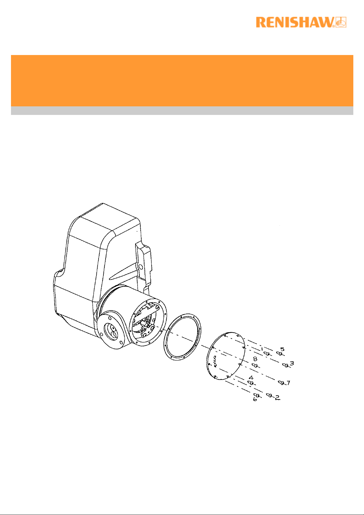
TSA
Motorised Tool Setting Arm
INITIAL PART/MODEL
New Mills, Wotton-under-Edge, F +44 (0) 1453 524201
Gloucestershire GL12 8JR E uk@renishaw.com
United Kingdom www.renishaw.com

© 2002 Renishaw. All rights reserved.
i
Renishaw® is a registered trademark of Renishaw plc.
This document may not be copied or reproduced in whole or in part, or transferred to
any other media or language, by any means, without the prior written permission of
Renishaw.
The publication of material within this document does not imply freedom from the
patent rights of Renishaw plc.
Disclaimer
Considerable effort has been made to ensure that the contents of this document are
free from inaccuracies and omissions. However, Renishaw makes no warranties with
respect to the contents of this document and specifically disclaims any implied
warranties. Renishaw reserves the right to make changes to this document and to
the product described herein without obligation to notify any person of such changes.
Trademarks
All brand names and product names used in this document are trade names, service
marks, trademarks, or registered trademarks of their respective owners.
Renishaw part no: H-2000-5090-01-A
Issued: 05 2002

Changes to specification
ii
Renishaw plc may modify or change its products or specifications without notice and
without obligation.
Warranty
This document defines the procedure for fault finding and repairing TSA returned to
the OEM after expiry of the warranty.
This document is to be used in conjunction with Renishaw parts supplied in the
Repair Kit (A-2116-0131).
Renishaw plc cannot take responsibility for any Renishaw product repaired by the
OEM.
The OEM may only repair Renishaw product if its warranty has expired.
Equipment requiring attention under warranty must be returned to your supplier. No
claims will be considered where Renishaw equipment has been misused, or
unauthorised persons have attempted repairs or adjustments.
PRECAUTIONS
Safety
Remove power before performing any maintenance operations.
Only competent persons observing relevant safety precautions may carry out repairs.
Anti static handling
The electronic circuit board assemblies within the TSA and those supplied in the
Repair Kit are sensitive to static discharge.
Anti static precautions must be observed during handling or installation of the
electronic circuit board assemblies. Failure to do so could result in permanent
damage to the electronics.
Product integrity
The torque wrench settings defined in this manual ensure the integrity of sealing
elements and fixings within the TSA.
Failure to use these settings when repairing TSA could result in coolant ingress or
poor repeatability.

CONTENTS.
iii
1.0 Initial inspection and test . . . . . . Page 1
2.0 Fault diagnosis . . . . . . . Page 3
3.0 Disassembly / reassembly . . . . . . Page 5
3.1 Hub cover plate and gasket. . . . . Page 5
3.2 Vanes and Soft Limits PCB . . . . Page 6
3.3 Hub assembly and Hard Limits PCB . . . Page 8
3.4 Base cover plate, gasket and Control PCB . . Page 9
4.0 Setting Up . . . . . . . Page 12
4.1 Control PCB wiring . . . . . . Page 12
4.2 Active stop opto switch vane . . . . Page 13
4.3 Stow position /Active opto switch vane. . . . Page 15
5.0 Troubleshooting . . . . . . . Page 16
5.1 Collisions . . . . . . . Page 16
5.2 Diagnostic LEDs . . . . . . Page 16
5.3 Trouble shooting charts . . . . . Page 17
5.4 Testing . . . . . . . Page 19

1.0 INITIAL INSPECTION AND FUNCTIONAL TEST.
Visual Inspection
Look for signs of damage by customer.
Look for signs of coolant ingress/damage.
Guidelines on Damage by Customer
Damage can be assessed by checking the arm tube for any distortion or creasing.
Check for any distortion in alignment of the probe module to the probe holder.
Inspect the hub and base castings for evidence of a machine crash i.e. chipped paint
or dents. Inspect the Damage Limitation Device (fitted between the arm and hub) for
cracks/distortion at the thin webs around the mounting holes.
Leaks
Leaks can only be positively identified upon removal of the cover plates as per
section 3. Leakage can manifest itself as any of a variety of failure modes.
Ingress will be identified by the presence of an oily film over internal components or
visible pools of coolant. If a leak has been over a long period of time, there will be
green deposits around the area of ingress.
Cable
Inspect cable for any sign of damage to the insulation, look for signs of crushing or
chafing along length of cable.
Functional Test
Attach complete TSA assembly to a rigid mounting and connect wiring in accordance
with the TSA Installation & User’s Guide (H-2000-5088-05) section 5.
Make use of the Diagnostic LEDs as detailed in section 5 and the TSA Installation &
User’s Guide section 11.
If the TSA hub is not already up in the ‘Stow’ position, drive it up to the ‘Stow’
position. If the hub fails to move consult section 2 (d) of Fault Diagnosis.
When up in the ‘Stow’ position, ensure: -‘Stow’ status LED is ON
‘Active’ status LED is OFF
If the LEDs do not show the correct status, consult section 2 (b) of Fault Diagnosis.
Drive the hub down to ‘Active’. See that the hub has a soft start and rotates smoothly
down into the ‘Active’ position.
1

When down in the ‘Active’ position, ensure: - ‘Stow’ status LED is OFF
‘Active’ status LED is ON
If the LEDs do not show the correct status, consult section 2 (a) of Fault Diagnosis.
Attempt to rotate the hub by applying slight hand pressure to the arm in the ‘Stow’
and ‘Active’ directions. Ensure there is no rotational movement of the hub with
respect to the base in either direction. If the hub can be moved freely consult section
2 (e) of Fault Diagnosis.
Drive the hub to a position halfway between ‘Stow’ and ‘Active’ and switch off the
power to the TSA.
Holding the hub casting firmly by hand, rotate it in both directions using moderate
force. The maximum permissible rotation is 2°. If the hub can be moved further than
this consult section 2 (e) of Fault Diagnosis.
Switch on the power to the TSA and allow the hub to continue to its ‘Stow’ position.
Disconnect the power to the TSA before removing it.
2
2.0 FAULT DIAGNOSIS.
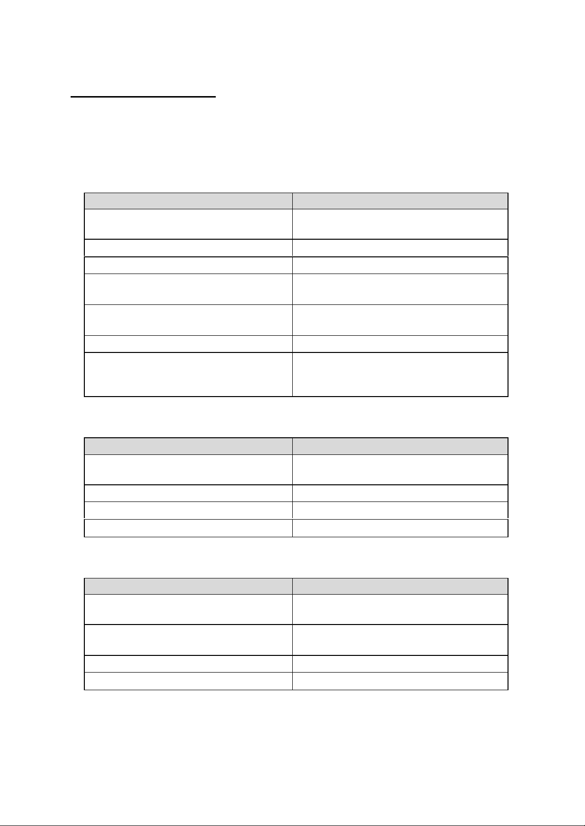
Possible Faults, Causes and Solutions
Problem: (a) Arm moves into ‘Active’ position, but ‘Active’ confirm LED is not lit.
Possible Causes Rectification
a) Opto switch vanes incorrectly set
or damaged
Consult section 4.2
b) Soft limits PCB defective Consult section 3.2
c) Hard limits PCB defective Consult section 3.3
d) Operating voltage <21.6 v (min)
e) Motor performance deterioration
Measure voltage with suitable meter
and correct supply if possible
Return TSA to Renishaw if
renewal/replacement is required
f) Control PCB fault Replace PCB, section 3.4
g) Wiring fault Check all wiring as per TSA
Installation & User’s Guide (H-2000-
5088-05) section 5.
(b) Arm moves into ‘Stow’ position, but ‘Stow’ confirm LED is not lit.
Possible Causes Rectification
a) Opto switch vanes incorrectly set
Consult section 4.3
or broken
b) Hard limits PCB defective Consult section 3.3
c) Control PCB fault Replace PCB, section 3.4
d) Loose mechanics Check all recommended torque values
(c) Arm moves too slow or with excessive judder
Possible Causes Rectification
a) Main bearing seizing up
Return TSA to Renishaw if
renewal/replacement is required
b) Motor defective
Return TSA to Renishaw if
renewal/replacement is required
c) Control PCB fault Replace PCB section 3.4
d) Loose mechanics Check all recommended torque values
3
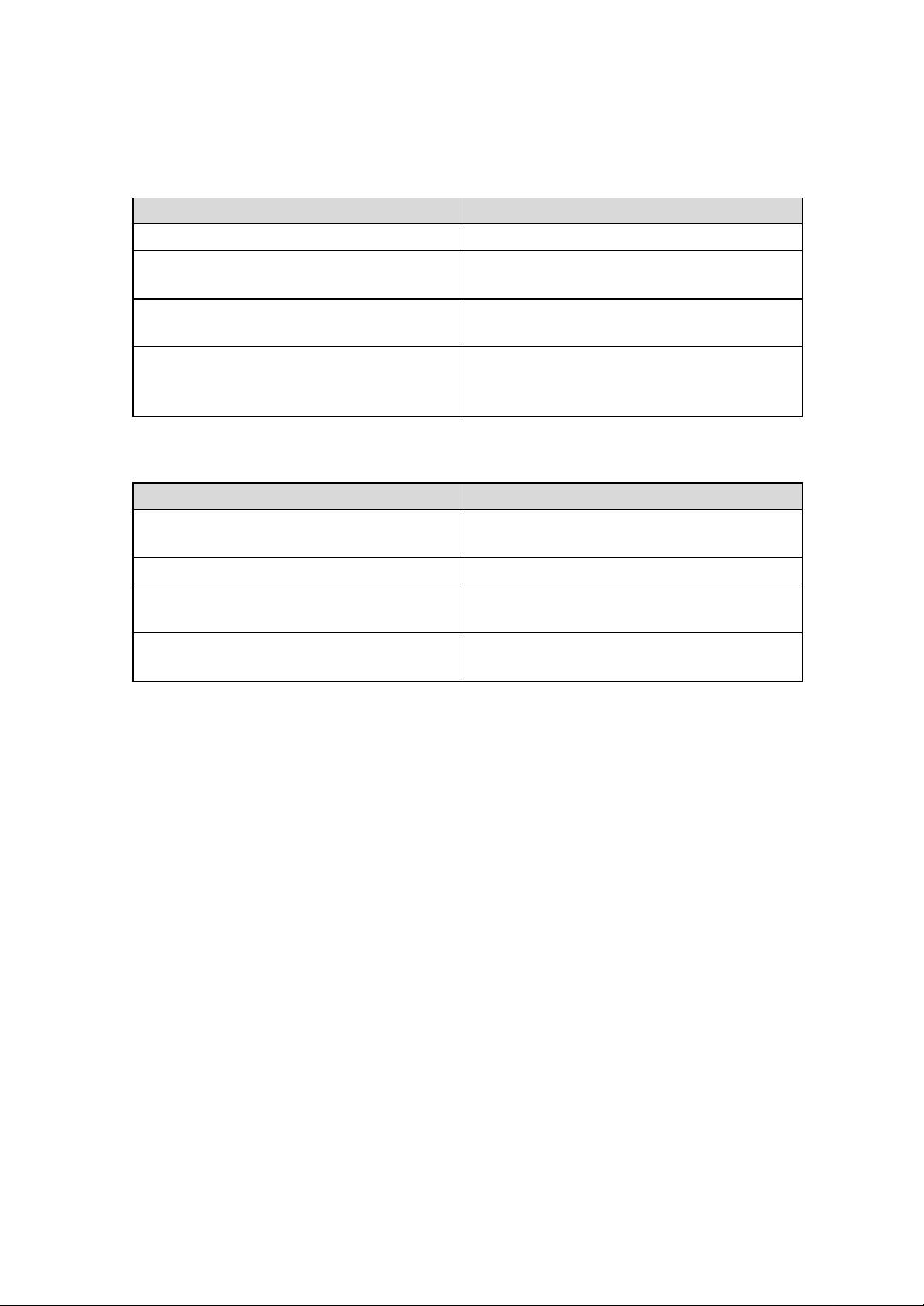
(d) Arm does not move in either direction.
Possible Causes Rectification
a) Control PCB failure Replace PCB section 3.4
b) Motor failure Return TSA to Renishaw if
renewal/replacement is required
c) Total main bearing seizure Return TSA to Renishaw if
renewal/replacement is required
d) Wiring fault Check all wiring as per TSA
Installation & User’s Guide (H-2000-
5088-05) section 5.
(e) Excessive hub end float and rotation
Possible Causes Rectification
a) Loose main bearing Return TSA to Renishaw if
renewal/replacement is required
b) Anchor plate screws loose Re-tighten screws, section 3.3
c) Loose kinematic structure Return TSA to Renishaw if
renewal/replacement is required
d) Excessive wear in motor assembly Return TSA to Renishaw if
renewal/replacement is required
For additional fault diagnosis, consult section 5.0 - Trouble Shooting
4
 Loading...