

Renishaw TS34 Installation And User Manual
Installation and user’s guide
H-2197-8500-02-A
TS34 - tool setting probe
English (EN)
日本語 (JP)

© 2010 - 2013 Renishaw plc. All rights reserved.
This document may not be copied or reproduced in
whole or in part, or transferred to any other media
or language, by any means, without the prior written
permission of Renishaw.
The publication of material within this document does
not imply freedom from the patent rights of Renishaw
plc.
Disclaimer
RENISHAW HAS MADE CONSIDERABLE EFFORTS
TO ENSURE THE CONTENT OF THIS DOCUMENT
IS CORRECT AT THE DATE OF PUBLICATION BUT
MAKES NO WARRANTIES OR REPRESENTATIONS
REGARDING THE CONTENT. RENISHAW
EXCLUDES LIABILITY, HOWSOEVER ARISING, FOR
ANY INACCURACIES IN THIS DOCUMENT.
Renishaw part no: H-2197-8500-02-A
Issued: 02.2010
Revised: 01.2013
Trade marks
RENISHAW and the probe symbol used in the
RENISHAW logo are registered trade marks of
Renishaw plc in the United Kingdom and other
countries. apply innovation and names and
designations of other Renishaw products and
technologies are trade marks of Renishaw plc or its
subsidiaries.
All other brand names and product names used in this
document are trade names, trade marks, or registered
trade marks of their respective owners.
Patent Notice
Features of products shown in this guide and of related
products are the subject of the following patents and/or
patent applications:
EP 0695926 EP 0967455
JP 4398011
US 5669151 US 6275,053

Installation and user’s guide
TS34
Tool setting probe
1
English
インストレーション及びユーザーズガイド
TS34
工具計測プローブ
2
日本語

1-2 Contents
Preliminary information .................................... 1-3
Warranty .................................................... 1-3
Changes to equipment .............................. 1-3
CNC machine ............................................ 1-3
Care of the probe ...................................... 1-3
WEEE directive ......................................... 1-4
Safety .............................................................. 1-5
TS34 probe system ......................................... 1-6
Introduction ............................................... 1-7
Operation ......................................................... 1-8
Achievable set-up tolerances .................... 1-8
Recommended rotating tool feedrates ...... 1-8
First touch - machine spindle rev/min........ 1-8
First touch - machine feedrate................... 1-8
Second touch - machine feedrate ............. 1-8
Software routines ...................................... 1-8
Specification .................................................... 1-9
Dimensions .................................................... 1-11
Installation ..................................................... 1-12
Cable ....................................................... 1-12
Conduit for cable protection .................... 1-12
Interface .................................................. 1-12
Recommended connection diagram for TS34
with HSI interface .......................................... 1-14
Stylus level setting ......................................... 1-15
Service and Maintenance .............................. 1-16
Service .................................................... 1-16
Maintenance ............................................ 1-16
Diaphragm maintenance ............................... 1-17
Parts list ......................................................... 1-18

1-3Preliminary information
Warranty
Equipment requiring attention under warranty
must be returned to your equipment supplier.
Unless otherwise specifically agreed in writing
between you and Renishaw, if you purchased
the equipment from a Renishaw company the
warranty provisions contained in Renishaw’s
CONDITIONS OF SALE apply. You should consult
these conditions in order to find out the details of
your warranty but in summary the main exclusions
from the warranty are if the equipment has been:
• neglected,mishandledorinappropriately
used; or
• modiedoralteredinanywayexceptwiththe
prior written agreement of Renishaw.
If you purchased the equipment from any other
supplier, you should contact them to find out what
repairs are covered by their warranty.
Changes to equipment
Renishaw reserve the right to change
specifications without obligation to change
equipment previously sold.
CNC machine
CNC machine tools must always be operated by
competent persons in accordance with
manufacturers instructions.
Care of the probe
Keep system components clean and treat the
probe as a precision tool.
1-4 Preliminary information
WEEE DIRECTIVE
The use of this symbol on Renishaw products and/or
accompanying documentation indicates that the product
should not be mixed with general household waste
upon disposal. It is the responsibility of the end user to
dispose of this product at a designated collection point
for waste electrical and electronic equipment (WEEE)
to enable reuse or recycling. Correct disposal of this
product will help to save valuable resources and prevent
potential negative effects on the environment. For more
information, please contact your local waste disposal
service or Renishaw distributor.

1-5Safety
Information for the user
In all applications involving the use of machine
tools or CMMs, eye protection is recommended.
Refer to the machine supplier’s operating
instructions.
The TS34 system must be installed by a
competent person, observing relevant safety
precautions. Before starting work, ensure that the
machine tool is in a safe condition with the power
switched OFF and the power supply to the HSI
disconnected.
Information for the machine supplier
It is the machine supplier’s responsibility to ensure
that the user is made aware of any hazards
involved in operation, including those mentioned in
Renishaw product documentation, and to ensure
that adequate guards and safety interlocks are
provided.
Under certain circumstances the probe signal
may falsely indicate a probe seated condition. Do
not rely on probe signals to stop the machines
movement.
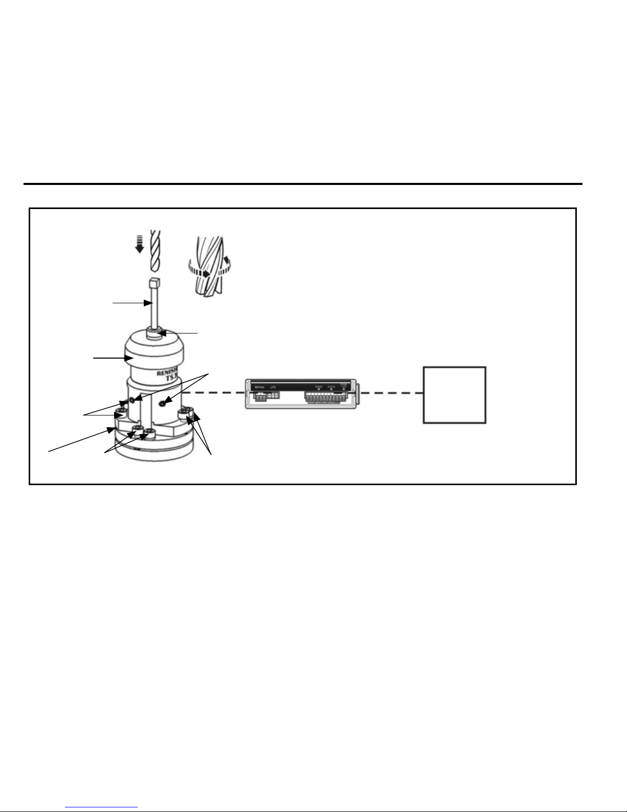
1-6 TS34 probe system
HSI interface unit
TS34 probe
Diameter setting
Rotate tool in
reverse direction
3
6
2
1
1. Stylus
2. Stylus holder for square styli
3. Swarf deflector
4. Probe’s base holding screws
5. Stylus level alignment – adjusting screws
6. Stylus level alignment – adjusting screws
7. Rotational axis adjustment – adjusting screws
8. Plinth
CNC
machine
control
4
5
8
7

1-7TS34 probe system (continued)
Introduction
The TS34 probe is used for tool setting on CNC
machining centres and is available as a rear or
side exit version.
For tool length measurements and broken tool
detection, the tool is driven against the probe’s
stylus in the Z axis. Rotating tools can be set in X
and Y axes for tool radius offsets.
Screw adjusters allow the stylus to be aligned with
the machine’s axes.
An interface unit processes signals between the
probe and the CNC control.

1-8 Operation
Achievable set-up tolerances
The tolerances to which tools can be set depend
upon the flatness and parallelism of the stylus tip
setting. A value of 5 µm (0.0002 in) front to back
and side to side is easily achievable over the flat
portion of the stylus tip, and 5 µm (0.0002 in)
parallelism is easily achievable with the axes of a
square tip stylus. This setting accuracy is sufficient
for the majority of tool setting applications.
Recommended rotating tool feedrates
Cutters should be rotated in reverse to the cutting
direction.
First touch – machine spindle rev/min
Rev/min for the first move against the probe stylus
is calculated from a surface cutting speed of
60 m/min (197 ft/min).
Spindle speed should be maintained within the
range 150 rev/min to 800 rev/min and relates
to cutters of Ø24 mm to Ø127 mm (Ø0.95 in to
Ø5.0 in).
The surface cutting speed is not maintained if
cutters smaller than Ø24 mm (Ø0.95) or larger
than Ø127 mm (Ø5.0 in) are used.
First touch – machine feedrate
The feedrate (f) is calculated as follows:
f = 0.16 × rev/min f units mm/min (diameter set)
f = 0.12 × rev/min f units mm/min (length set)
Second touch – machine feedrate
800 rev/min, 4 mm/min (0.16 in/min) feedrate.
Software routines
Software routines for tool setting are available
from Renishaw for various machine controllers
and are described in data sheet H-2000-2289.

1-9Specification
Principal application
Tool measuring and broken tool detection on all sizes of vertical and
horizontal machining centres
Transmission type
Hard-wired transmission
Receiver/interface
HSI
Recommended styli
Square tip stylus (tungsten carbide, 75 Rockwell C)
Weight with stylus
660 g (23.28 oz)
Cable TS34R TS34S
Cable length: 5.0 m (16.4 ft)
long.
Cable specification: Ø5.2 mm
(0.20 in), 2-core screened cable,
each core 72 x 0.08 mm
Cable length: 5.0 m (16.4 ft)
long.
Cable specification: Ø4.4 mm
(0.17 in), 4-core screened cable,
each core 7 x 0.2 mm
Sense directions
±X, ±Y, +Z
Unidirectional repeatability
1.00 µm (40 µin) 2σ (see note 1)
Stylus trigger force
(see notes 2 and 3)
XY low force
XY high force
+Z direction
0.65 N, 66 gf (2.34 ozf)
1.42 N, 145 gf (5.11 ozf)
5.50 N, 561 gf (19.78 ozf)
Stylus overtravel
XY
+Z direction
±9°
4 mm (0.16 in)

1-10
IP rating
IPX8 (EN/IEC 60529)
Storage temperature
-10 °C to +70 °C (+14 °F to +158 °F)
Operating temperature
+5 °C to +60 °C (+41 °F to +140 °F)
Specification (continued)
Note 1 Performance specification is tested at a standard test velocity of 480 mm/min (18.9 in/min) with a 35 mm stylus. Significantly
higher velocity is possible depending on application requirements.
Note 2 Trigger force, which is critical in some applications, is the force exerted on the component by the stylus when the probe
triggers. The maximum force applied will occur after the trigger point i.e. overtravel. The force value depends on related
variables including measuring speed and machine deceleration. Trigger force is measured with a 50 mm (1.97 in) stylus.
Note 3 These are the factory settings, manual adjustment is not possible.
NOTE: For stylus recommendations, please refer to the Styli and accessories technical specification
(H-1000-3200)
 Loading...