

Page 1
Installation
H-2000-501
and
user’s
8-06-D
guide
RENISHAW
apply
innovation’"
TS27R
i
tool
setting
:
probe
:
r
m
1
English
Francais
Deutsch
Itaiiano
Page 2

1
Installation
user's
and
TS27R
guide
C€
English
2
Frangais
3
Deutsch
4
Italian©
Tool
Manuel
Installations-
TS27R
Manuale
d'installation
Palpeur
Werkzeugmess-System
zur
Werkzeugeinstellung
Sonda
degli
setting
d’outil
und
d’installazione
la
per
utensili
probe
et
reglage
de
TS27R
Benutzerhandbuch
regolazione
TS27R
d'utilisation
e
d’uso
C€
C€
C€
I
:
,
Page 3
FCC
This
Section
device
15.19
complies
conditions:
This
1.
2.
This
undesired
FCC
Section
This
equipment
pursuant
against
equipment
used
in
may
device
device
must
operation.
15.105
to
Part
harmful
generates,
accordance
communications.
interference,
FCC
user
The
pic,
or
FCC
Section
The
user
computer,
limits.
Section
is
cautioned
authorised
is
also
must
in
15.21
15.27
with
not
cause
accept
been
has
of
the
15
interference
uses,
the
with
Operation
which
case
that
representative
cautioned
be
connected
1
Part
harmful
any
tested
FCC
rules.
when
and
instruction
this
of
you
will
any
changes
that
any
with
FCC
DECLARATION
the
of
5
FCC
interference.
interference
and
found
These
the
equipment
can
radiate
manual,
equipment
be
required
or
could
void
peripheral
high-quality
a
rules.
Operation
received,
comply
to
limits
radio
are
is
frequency
may
a
in
to
correct
including
with
designed
operated
cause
residential
modifications
the
user's
authority
device
installed
shielded
(USA)
the
harmful
the
expressly
not
cable
energy
subject
is
interference
limits
foraClass
to
provide
in
a
commercial
and,
interference
is
likely
area
interference
approved
to
operate
this
with
to
insure
to
the
following
that
A
reasonable
environment.
if
installed
not
cause
to
your
at
the
equipment.
equipment
compliance
may
cause
digital
to
radio
harmful
own
by
Renishaw
such
with
two
device,
protection
This
and
expense.
as
a
FCC
TS27R
probe
Operation
Specification
Interface
Dimensions
Installation
Wiring
connection
The
TS27R
Before
starting
and
the
power
systc
unit
c
system
work
suppl
Page 4

TS27R
tool
setting
probe
TS27R
Operation
Specification
Interface
Dimensions
Installation
Wiring
The
Before
and
probe
unit
connection
TS27R
starting
power
the
system
system
work,
supply
diagrams
must
be
ensure
the
to
Installation
by
competent
the
machine
8-4
a
disconnected.
installed
that
8/MI
Ml
user's
and
Contents
-4
-6
SAFETY
in
is
Fitting
Break
Stylus
Square
Service
Diaphragm
Parts
person,
a
1-1
1-2
1-3
1-3
1
1-5
1
tool
list
safe
guide
the
stylus
stem
setting
level
stylus
and
maintenance
maintenance
observing
condition
captive
and
alignment
relevant
with
the
.
link
safety
power
precautions.
switched
OFF
1-10
1-11
1-12
1-13
1-14
1-15
1-16
Page 5
to
equipment
reserves
without
machine
machine
tools
persons
the
of
probe
components
and
logo
in
pic
innovation
names
brand
are
registered
or
owners.
notice
products
of
products,
patent
and
righttochange
the
notice.
always
must
accordance
in
instructions.
system
reasonably
the
the
are
is
trade
UK
a
emblem
probe
registered
other
and
trademarkofRenishaw
and
product
names,
trademarksoftheir
in
shown
subject
are
the
applications:
GB
2277593
IT
1273643
1,445/1997
JP
2,098,080
JP
320,394/1994
JP
be
operated
with
clean.
trademarks
countries.
names
service
this
user's
of
JP
US
US
US
US
by
the
in
used
of
used
marks,
guide,
following
the
2002-531,839
5,446,970
5,647,137
5,669,151
6,470,584
the
pic.
in
and
B1
i
CNC
machine
controi
I
The
TS27R
CNC
machini
For
tool
detection,
in
stylus
in
X
and
adjust*
Screw
the
with
interface
An
probe
the
Cabl
lengt
the
the
for
Y
mact
anc
p
1
i
in
or
of
Changes
Renishaw
specifications
CNC
CNC
competent
manufacturer’s
Care
Keep
Trademarks
RENISHAW®
RENISHAW
Renishaw
apply
other
All
this
document
trademarks,
respective
Patent
Features
of
related
patents
4413968
DE
0293036
EP
0695926
EP
0748669
EP
1051668
EP
©
1
995
-
This
document
or
whole
language,
permission
The
publication
does
not
Renishaw
2005
in
part,
by
of
imply
pic.
Renishaw
may
not
or
transferred
means,
any
Renishaw.
of
material
freedom
be
from
pic.
All
copied
to
without
within
the
rights
reproduced
or
other
any
prior
the
this
document
patent
reserved.
media
written
of
rights
Disclaimer
to
free
to
the
disclaims
the
right
the
product
to
to
notify
warranty
claims
have
8-06-D
ensure
that
from
Renishaw
contents
any
implied
make
to
any
must
be
will
has
been
been
made
Considerable
the
contents
inaccuracies
makes
this
document
warranties.
changes
described
person
*
Warranty
Equipment
be
returned
considered
misused,
attempted
Renishaw
warranties
no
Renishaw
to
this
herein
such
of
requiring
to
where
repairs
or
by
part
effort
this
of
and
and
document
changes.
your
unauthorised
no:
been
has
document
omissions.
with
specifically
reserves
obligation
without
attention
supplier.
Renishaw
adjustments
or
H-2000-501
are
However,
respect
and
under
No
equipment
persons.
Issued:
04.05
Page 6
Cable
:
1
CNC
machine
control
i
i
Alternative
nnRENlSHAW.
j
j
r
.
T
Iff
®
II
Mi
8-4
jÿHRENISHAW*
t.
|fe>~“£'nE"f*eE
-
m
Ml
interface
INTERFACE
PROBE
sss®
interface
8
interface
'OS
setting
tool
1-1
in
-
a
TS27R
PROBE
SYSTEM
Diameter
units
__
-”-f
H
n
i
TS27R
10
probe
7
5V
Z
X/Y
=
V
Rotate
reverse
c!;i'
direction
//
&
t.®
i!
7
<<3
9
H
4
2
I
3
:
6
m
8
Machine
Stylus
setting
broken
the
probe
be
can
aligned
be
between
on
tool
set
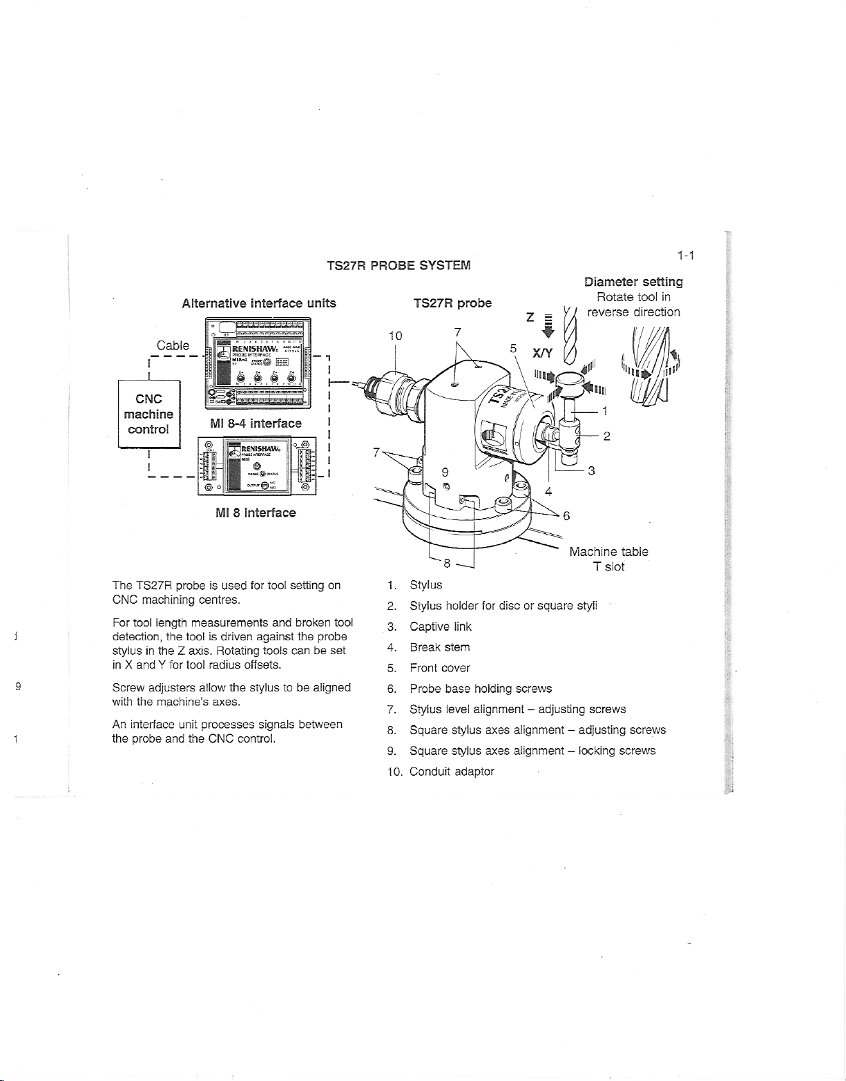
The
CNC
For
j
9
1
tool
detection,
stylus
in
X
Screw
with
interface
An
the
probe
TS27R
machining
length
the
theZaxis.
in
and
for
Y
adjusters
the
machine's
and
probe
is
used
centres.
measurements
is
driven
tool
Rotating
radius
tool
allow
axes.
unit
processes
the
CNC
offsets.
the
control.
for
tool
against
tools
stylus
signals
and
to
1
2.
3.
4.
5.
6.
7.
8.
9.
10.
.
Stylus
Captive
Break
Front
Probe
Stylus
Square
Square
Conduit
holder
link
stem
for
disc
cover
base
holding
alignment-adjusting
level
stylus
axes
axes
stylus
adaptor
or
square
styli
screws
alignment-adjusting
alignment
-
locking
T
slot
screws
table
screws
screws
=
i
Page 7
1-2
OPERATION
ACHIEVABLE
The
tolerances
upon
the
setting.
side
to
of
stylus
the
easily
achievable
stylus.
This
majority
flatness
value
A
side
of
SET-UP
is
easily
tip,
setting
tool
to
of
setting
RECOMMENDED
Cutters
should
be
direction.
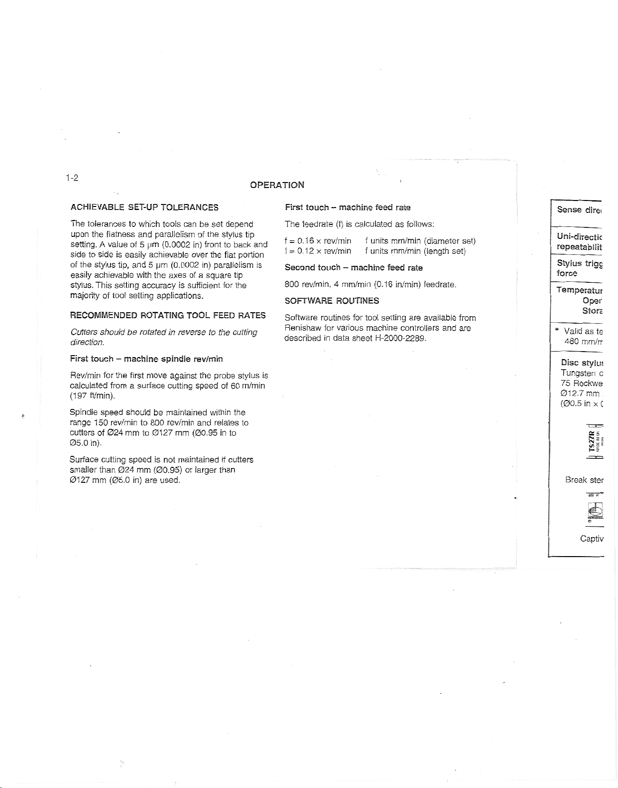
First
touch-machine
Rev/min
calculated
(197
Spindle
range
cutters
05.0
Surface
smaller
0127
for
ft/min).
speed
150
of
in).
cutting
than
mm
the
from
rev/min
024
mm
024
(05.0
first
a
should
speed
which
and
parallelism
5
pm
achievable
and
5
pm
with
the
accuracy
applications.
ROTATING
rotated
move
surface
be
to
800
01
to
is
(00.95)
mm
in)
are
TOLERANCES
tools
can
be
the
of
(0.0002
spindle
in)
over
(0.0002
axes
of
is
sufficient
TOOL
reverse
in
rev/min
against
cutting
maintained
rev/min
(00.95
mm
27
not
maintained
or
front
in)
square
a
to
the
speed
and
larger
the
within
used.
set
depend
stylus
back
to
portion
flat
parallelism
tip
for
the
FEED
RATES
the
cutting
stylus
probe
60
m/min
of
the
relates
to
to
in
if
cutters
than
tip
and
is
is
First
touch-machine
The
feedrate
x
0.16
f
=
f
Second
800
SOFTWARE
Software
x
0.12
=
touch-machine
rev/min,
routines
Renishaw
described
is
(f)
rev/min
rev/min
4
mm/min
ROUTINES
various
for
data
in
feed
calculated
f
units
f
units
(0.16
for
tool
machine
H-2000-2289.
sheet
rate
as
mm/min
mm/min
feed
in/min)
setting
follows:
(diameter
(length
rate
feedrate.
available
are
controllers
and
set)
set)
from
are
Sense
direi
Uni-directic
repeatabilit
Stylus
trigc
force
Temperatur
Oper
Store
Valid
480
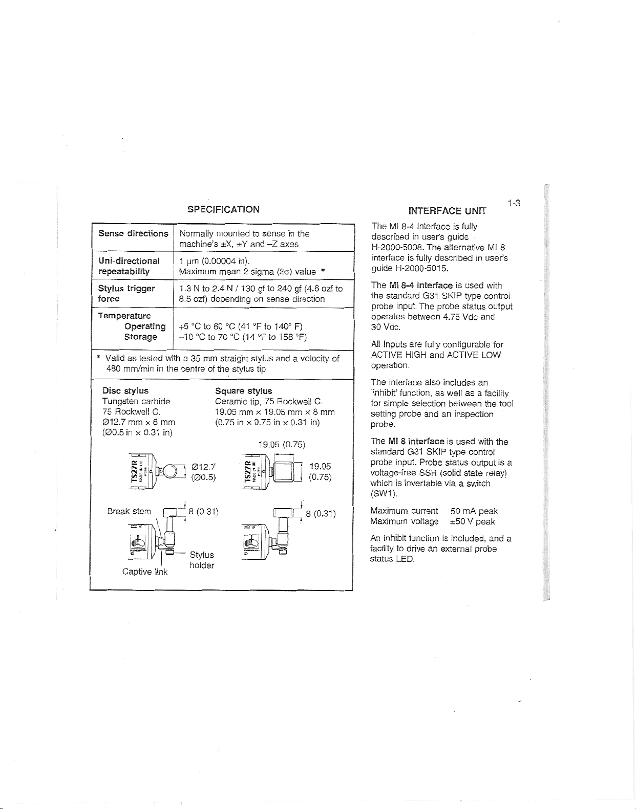
Disc
as
mm/rr
stylus
*
Tungsten
75
Rockwe
012.7
mm
(00.5
in
x
st
§i>
Break
ster
te
c
C
i
=
s
Captiv
Page 8
Sense
directions
Uni-directional
repeatability
Stylus
trigger
force
Temperature
Operating
Storage
Valid
as
*
480
Disc
Tungsten
75
012.7
(00.5
tested
mm/min
stylus
carbide
Rockwell
mm
x
in
2=5
gjllBCC
Break
stem
Captive
C.
x
0.31
Tl
in
8
link
SPECIFICATION
Normally
machine’s
1
pm
Maximum
1
N
.3
ozf)
8.5
°C
+5
°C
-10
a
35
with
the
centre
mm
in)
i
012.7
(00.5)
8
(0.31)
Stylus
holder
mounted
±X,
(0.00004
mean
to
2.4
depending
to
60
°C
70
to
straight
mm
of
the
Square
Ceramic
19.05
(0.75
N
°C
stylus
±Y
/
in
in).
2
1
(41
(14
mm
to
and
sigma
30
on
°F
stylus
stylus
tip,
x
x
0.75
S*
S
£2
sense
-Z
to
gf
sense
to
to
°F
tip
75
19.05
19.05
in
axes
(2ct)
value
gf
240
direction
140°
F)
°F)
158
a
and
Rockwell
mm
in
x
0.31
(0.75)
T|
iU
IL.
the
(4.6
velocity
C.
x
8
in)
19.05
|
(0.75)
8
(0.31)
*
ozf
mm
user’s
control
and
LOW
an
a
facility
the
with
relay)
peak
Ml
8
with
output
for
tool
the
is
and
1-3
a
a
INTERFACE
Ml
The
described
H-2000-5008.
interface
guide
to
of
The
the
probe
operates
30
Vdc.
All
inputs
ACTIVE
operation.
The
‘inhibit’
simple
for
setting
probe.
The
standard
probe
voltage-free
interface
8-4
in
user’s
fully
is
H-2000-5015.
8-4
Mi
interface
standard
input.
between
G31
The
are
HIGH
interface
function,
selection
probe
Mi
8
interface
G31
input.
Probe
SSR
The
fully
and
also
and
SKIP
whichisinvertable
(SW1).
Maximum
Maximum
An
facility
status
inhibit
to
LED.
current
voltage
function
drive
an
UNIT
is
fully
guide
alternative
described
is
used
SKIP
type
status
probe
4.75
Vdc
configurable
ACTIVE
includes
well
as
as
between
an
inspection
is
used
type
control
status
(solid
state
viaaswitch
50
mA
V
±50
is
included,
external
in
output
peak
probe
I
Page 9
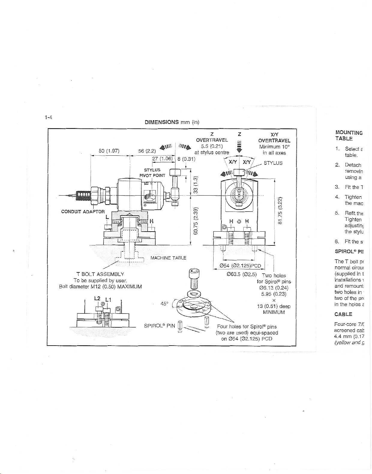
1-4
DIMENSIONS
mm
(in)
CONDUIT
Bolt
diameter
aaaaa
T
To
I
r
be
-
V-
ADAPTOR
BOLT
supplied
M12
L2
ijjfjjll
ifr
50
(1.97)
TV-
1
SI
—
j
‘“Ml
I
r'i
!'
ASSEMBLY
by
user.
(0.50)
MAXIMUM
L1
&
I
I
¥
j
32
56
(2.2)
STYLUS
PIVOT
PC
e
_1
M
L.
SPIROL®
4\\Wj////14
(1.06)
27
!
POINT
:
/
MACHINE
45°
PIN
_
I
8
¥
TABLE
Crt
!-•
ff
CD
(0.31)
l
I
1
H
tl
at
3-
LO
o
:z
Z
OVERTRAVEL
(0.21)
5.5
stylus
centre
4\WQ3ÿ.
Prh
_
054
cu
Four
(two
on
z
X/Y
X/Y
Jr-
H@H
rh
li
V
(02.125)PCD
(02.5)
063.5
for
holes
used)
are
(02.125)
054
X/Y
OVERTRAVEL
Minimum
in
all
STYLUS
I
J
Two
for
Spiral®
06.13
5.95
X
13
(0.51)
MINIMUM
Spiral®
pins
equi-spaced
PCD
10°
axes
CM
Si
£2.
Lfl
!
5
holes
pins
(0.24)
(0.23)
deep
MOUNTING
TABLE
1.
Select
table.
2.
Detach
removin
using
a
3.
Fit
the
4.
Tighten
the
mac
5.
Refit
the
Tighten
adjusiini
the
styiu
6.
Fit
the
SPIROL®
The
normal
(supplied
installations
and
two
two
in
CABLE
Four-core
screened
4.4
(yellow
T
remount
holes
of
the
mm
bolt
circui
the
holes
(0.17
and
PI!
pi
in
in
pr<
7/C
cat
E
1
s
t
\
c
5
Page 10

r
IL
ns
l)
ep
MOUNTING
TABLE
Select
1.
table.
Detach
2.
removing
using
Fit
3.
theTbolt
Tighten
4.
the
machine
5.
Refit
the
Tighten
adjusting
stylus
the
6.
the
Fit
SPIROL®
The
T
bolt
normal
circumstances.
(supplied
in
installations
and
remount
holes
two
of
the
two
in
the
holes
CABLE
Four-core
screened
mm
(0.17
and
4.4
(yellow
THE
a
position
the
the
a
mm
4
the
probe
the
screws
alignment
stylus
PINS
provides
the
where
the
in
the
probe
and
7/0.2
cable
in).
green
PROBE
for
the
probe
base
screws
two
AF
hexagon
(not
supplied
T
two
(see
probe
TS27R.
machine
base
refit
polyurethane
10m
bolt
table.
onto
screws
L1
(see
page
adequate
there
the
(32.8
Probe
not
secure
to
the
andL2loose
(see
pages
However
kit)
may
is
To
table
holes.
probe
circuit
used).
THE
ON
probe
the
from
H
and
key.
by
the
base
H
firmly.
page
1-10
1-4)
ciamping
two
be
a
requirement
fit
the
to
correspond
Place
base.
insulated
ft)
long.
-
red
MACHINE
machine
on
the
by
probe
the
screw
Renishaw).
base
probe
the
fit
and
Keep
the
before
1-12).
1-11).
and
ail
for
Spiral®
fitted
on
to
Spiral®
pins,
the
Spiral®
and
diameter
Cable
blue
and
INSTALLATION
L1
to
screws.
setting
pins
remove
drill
with
pins
NOTE
The
100
possible
cores
connected
EXTENSION
Probe
permitted
to
7/0.2
cable.
Maximum
Two-core
screened
joins.
CONDUIT
conduit,
1
mm
Conduit
recommends
(0.43
Renishaw
EF
installations.
01
Cable
Conduit
:
cable
screen
capacitor
nF
earth
to
CABLE
interface
mm
FOR
or
a
The
in)
adaptor
loops.
the
m
(15
length:
cable
-
m
25
polyurethene
Maintain
CABLE
the
PROTECTION
that
TS27R
flexible
alternative,
conduit
conduit.
suitable
T
:
n
E
is
connectedtothe
inside
the
TS27R
Ensure
appropriate
maximum
(82
ft)
long
insulated
screen
Thomas
adaptor
BS
G
H
n
to
the
cable
on
input
extension)
through
and
is
fitted
s
machine
prevent
screen
the
and
the
Betts
Type
all
to
accepts
via
is
interface.
1-5
a
til
Page 11
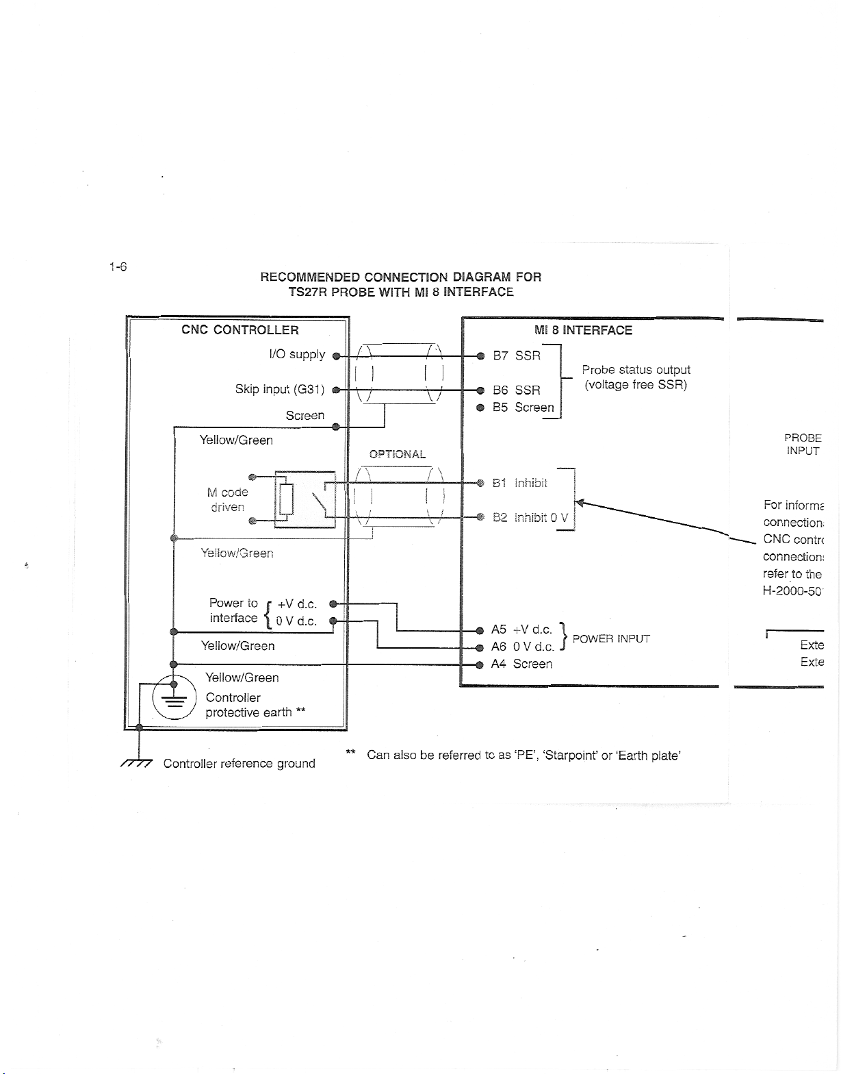
1-6
CNC
CONTROLLER
Yellow/Green
M
driven
6-
Yellow/Green
*
RECOMMENDED
I/O
input
Skip
code
*ÿ
TS27R
supply
(G31)
Screen
u
r
\
CONNECTION
PROBE
©-
A
a-
X7
I
WITH
OPTIONAL
INTERFACE
8
Ml
A
tt
n
_
\
i
.
.
DIAGRAM
B7
-c
B6
a
B5
B1
B2
FOR
Mi
SSR
SSR
Screen
Inhibit
inhibit
8
INTERFACE
Probe
(voltage
OV
status
free
output
SSR)
PROBE
INPUT
For
informs
connection.
CNC
contrc
connection:
refer
to
the
H-2000-50'
d.c.
**
s>
f
A5+Vd.c.
A6
•o
A4
-®
OVd.c.
Screen
POWER
}
INPUT
Exte
Exte
<ÿ
Power
to
interface
Yeliow/Green
Yellow/Green
Controller
protective
{
earth
+V
OVd.c.
also
Can
//
//
Controller
reference
ground
**
be
referred
as
to
‘PE’,
‘Starpoinf
or
‘Earth
plate’
Page 12
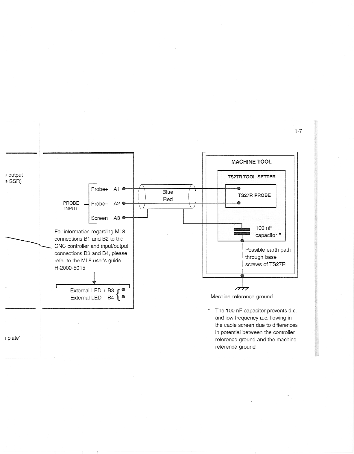
1-7
;
output
SSR)
3
i
plate’
Probe+
PROBE
INPUT
For
information
connections
CNC
controller
connectionsB3and
refer
H-2000-5015
r
the
to
External
External
B1
Ml
i
Probe-
Screen
regarding
and
and
user’s
8
LED
LED
A1
®-
A2
®-
A3
8
Mi
the
to
B2
input/output
B4,
please
guide
B3
+
{:
-
B4
TOOL
TOOL
SETTER
PROBE
Blue
Red
MACHINE
TS27R
\
/
-©
TS27R
-O
XI
nF
100
capacitor
o
Possible
through
screws
i
Machine
The
*
in
reference
1
00
and
low
the
cable
potential
reference
reference
capacitor
nF
frequency
screen
between
ground
ground
ground
a.c.
due
and
earth
base
of
TS27R
prevents
flowing
to
differences
the
controller
the
*
path
d.c.
in
machine
j
Page 13
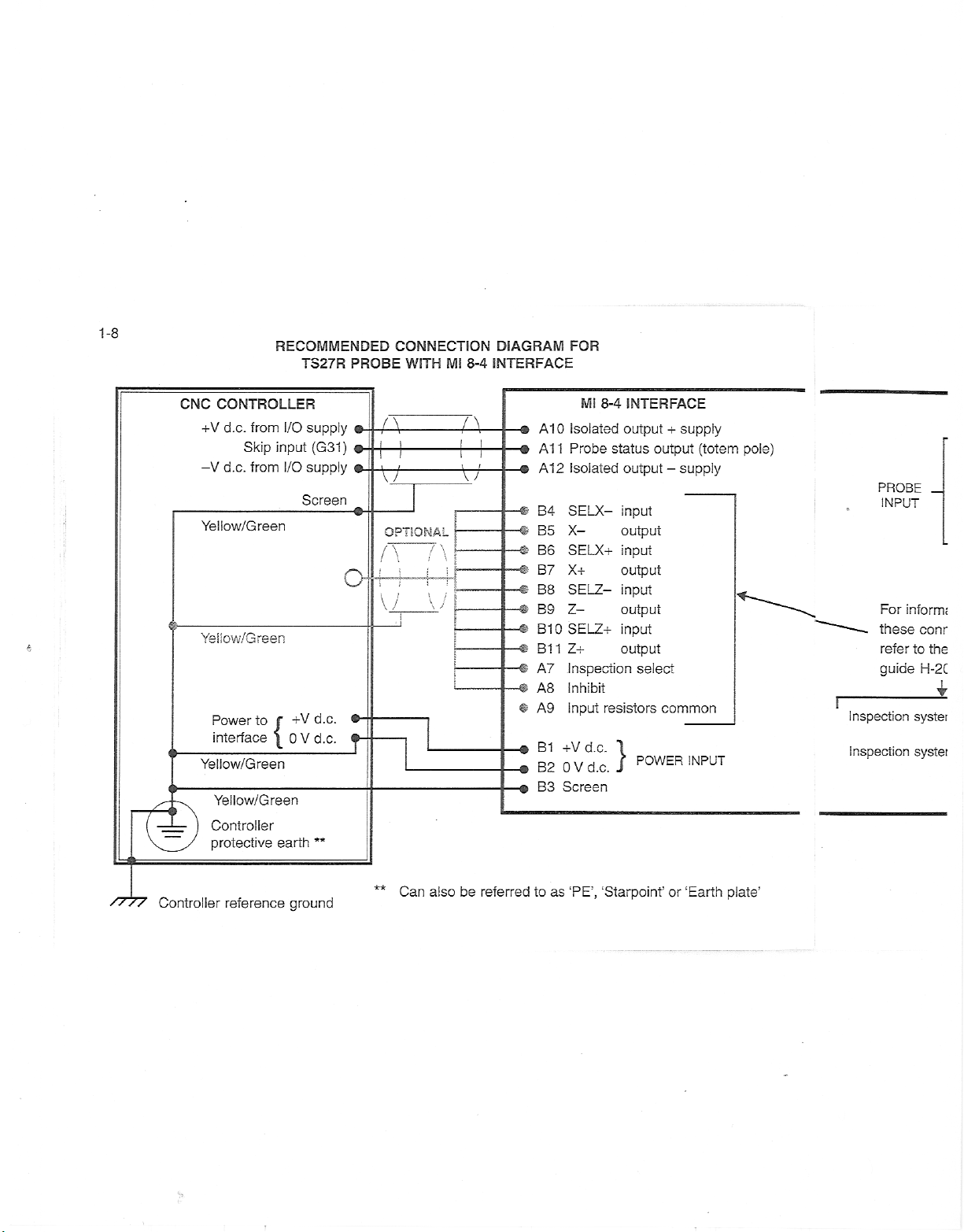
1-8
CNC
CONTROLLER
+V
d.c.
d.c.
-V
Yellow/Green
Yeiiow/Green
*
Power
interface
<ÿ
Yellow/Green
<ÿ
Yellow/Green
RECOMMENDED
TS27R
from
Skip
from
to
I/O
input
I/O
{
supply
supply
Screen
+V
V
0
(G31)
d.c.
d.c.
PROBE
*ÿ
A
©ÿ
©.
v
OPTIONAL
i
\j
f-
CONNECTION
Ml
8-4
WITH
n
7
v7
:
DIAGRAM
INTERFACE
-©
-©
-&
4b
«
#
©
-9
«
A1
A1
A12
B4
B5
B6
B7
B8
B9
B10
B11
AT
A8
A9
B1
B2
B3
0
1
FOR
Ml
8-4
Isolated
Probe
status
Isolated
SELX-
X-
SELX+
X+
SELZ-
Z—
SELZ+
Z+
Inspection
Inhibit
resistors
Input
+V
d.c.
V
d.c.
0
Screen
INTERFACE
output
+
output
-
output
input
output
input
output
input
output
input
output
select
common
POWER
}
supply
(totem
supply
INPUT
pole)
r
Inspection
Inspection
PROBE
INPUT
inform;
For
these
refer
guide
conr
to
the
H-2C
systet
systei
Controller
protective
earth
**
Can
//
//
Controller
reference
ground
**
also
be
referred
as
to
‘PE’,
‘Starpoint’
or
‘Earth
plate’
Page 14
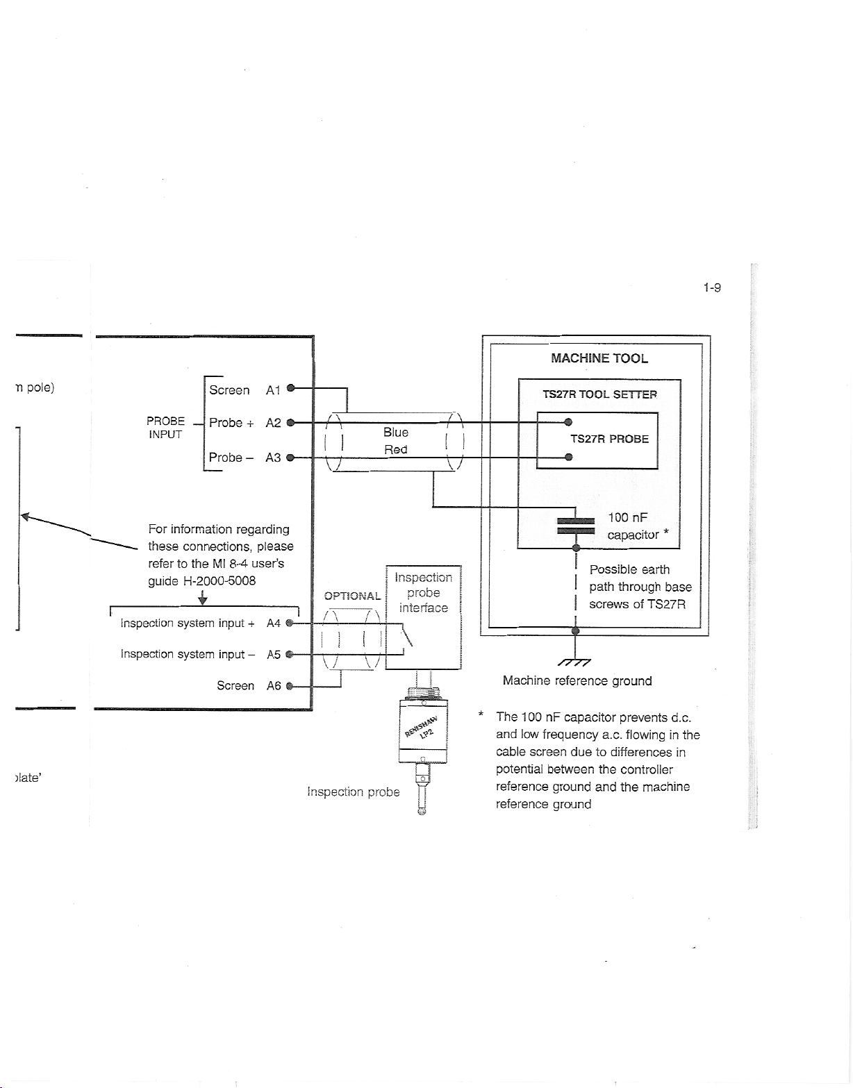
1-9
n
)late’
pole)
r
Inspection
Inspection
PROBE
INPUT
For
information
these
refer
guide
Screen
Probe
Probe
connections,
the
to
MI
8-4
H-2000-5008
i
input
system
input
system
Screen
A1
-T-
A2
A3
-
regarding
please
user’s
A4
+
A5
-
A6
®-
®-
@-
Inspection
A
XT
OPTIONAL
n
IX
i
Y7
J
T7
probe
Blue
Red
Inspection
probe
interface
\
-Q—
A
tr
Machine
The
*
and
cable
potential
reference
reference
TS27R
00
1
low
frequency
screen
MACHINE
TOOL
TS27R
-•
t-
-<
reference
capacitor
nF
due
between
ground
ground
TOOL
SETTER
PROBE
100
capacitor
Possibie
path
through
screws
ground
prevents
a.c.
to
differences
the
controller
and
the
nF
earth
of
TS27R
flowing
machine
*
base
d.c.
in
in
the
;
Page 15
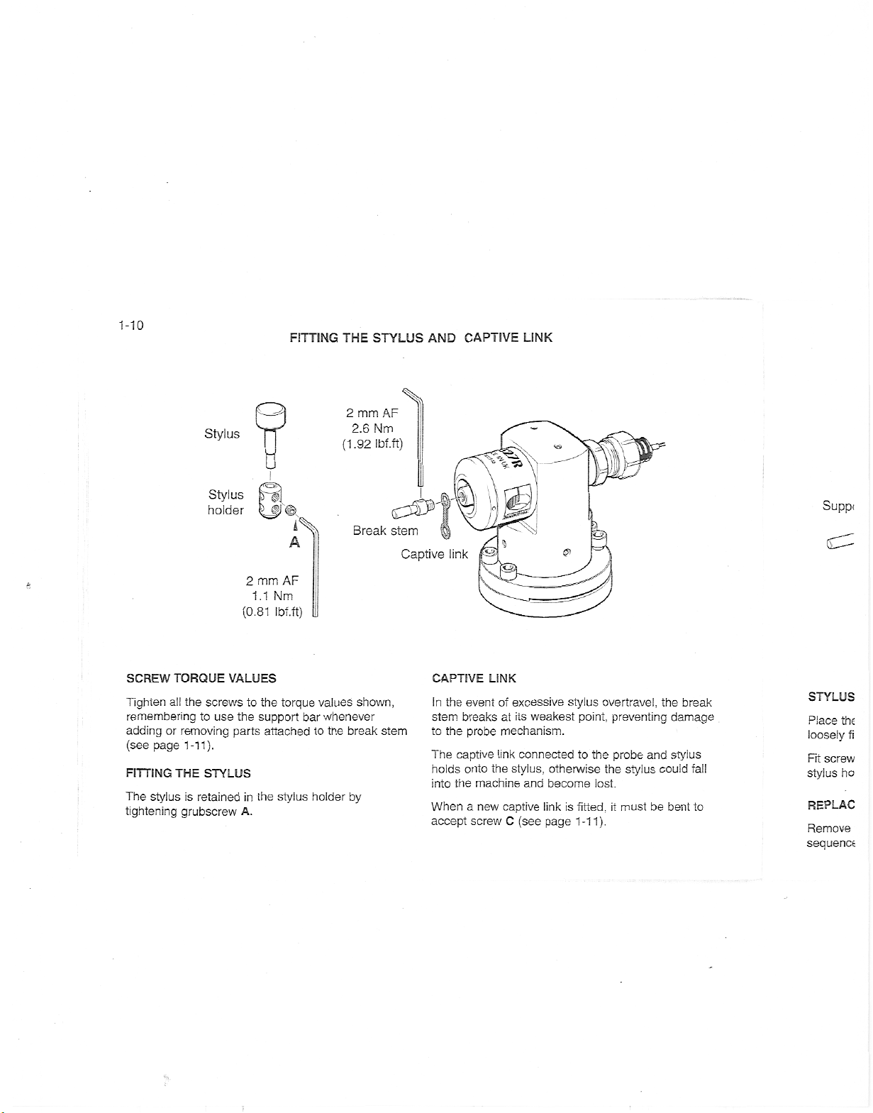
1-10
FITTING
THE
STYLUS
AND
CAPTIVE
LINK
X
AF
2
Stylus
0
Stylus
holder
k
AF
2
*
mm
1.1
(0.81
Nm
Ibf.ft)
2.6
(1
mm
Nm
Ibf.ft)
.92
Break
stem
Captive
link
sÿ-
e
—
;
Supp<
C'
0c
all
or
page
stylus
TORQUE
removing
1-11).
THE
grubscrew
SCREW
Tighten
remembering
adding
(see
FITTING
The
tightening
VALUES
screws
the
use
the
to
parts
STYLUS
is
retainedinthe
to
A.
the
torque
support
attached
stylus
values
whenever
bar
to
holder
the
shown,
break
by
stem
CAPTIVE
the
In
event
breaksatits
stem
probe
the
to
The
captive
holds
onto
the
into
When
a
accept
LINK
of
mechanism.
link
the
machine
new
screw
excessive
weakest
connected
stylus,
and
captive
C
(see
stylus
otherwise
become
is
link
page
1-11).
point,
the
to
lost.
fitted,
overtravel,
preventing
probe
the
stylus
it
must
and
be
the
damage
stylus
could
bent
break
fall
to
STYLUS
Place
the
loosely
fi
screw
Fit
ho
stylus
REPLAC
Remove
sequence
Page 16
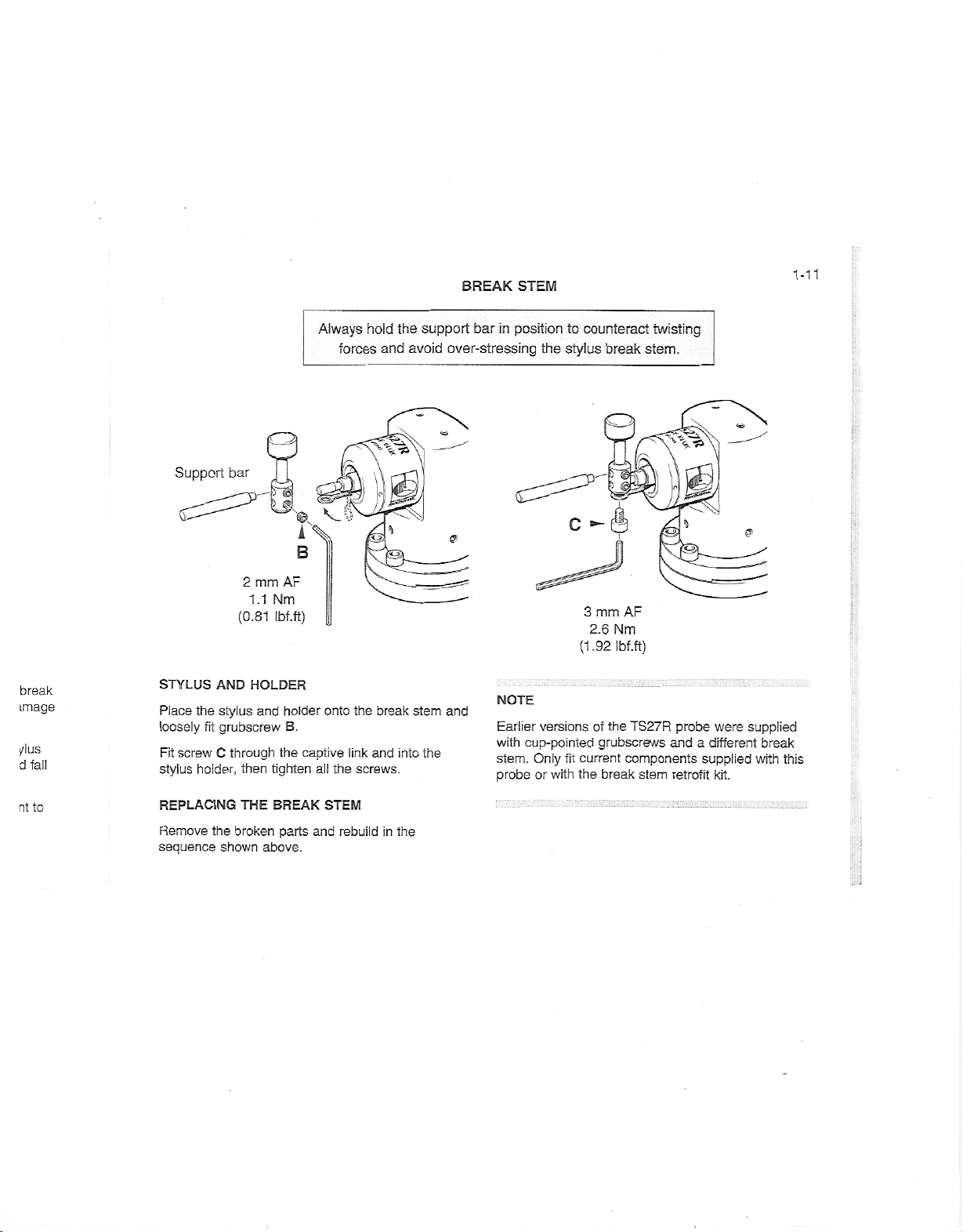
BREAK
STEM
1-11
break
image
/lus
d
fall
Support
STYLUS
Place
the
loosely
Fit
screw
stylus
holder,
bar
(0.81
AND
stylus
grubscrew
fit
C
through
mm
2
Nm
1.1
Ibf.ft)
HOLDER
and
tighten
then
AX
B
AF
holder
B.
the
Always
onto
captive
all
forces
the
link
the
screws.
hold
and
break
and
the
support
avoid
over-stressing
%
'G)
into
stem
the
a
and
bar
position
in
NOTE
Earlier
with
stem.
probe
cup-pointed
to
counteract
stylus
the
c
-
mm
3
2.6
(1.92
versionsofthe
Only
or
with
current
fit
the
grubscrews
break
break
stem.
ft
AF
Nm
Ibf.ft)
TS27R
components
stem
twisting
'
%
r<
probe
and
retrofit
were
a
different
supplied
kit.
<0
&
supplied
break
with
this
parts
STEM
and
rebuildinthe
j
THE
to
nt
REPLACING
Remove
sequence
the
shown
BREAK
broken
above.
Page 17
1-12
Square
Yo
V
stylus
TAKE
W,
Ml
Disc
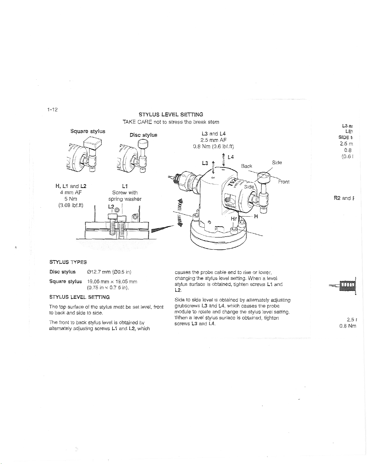
STYLUS
CARE
stylus
_
j
LEVEL
nottostress
SETTING
the
break
0.8
L3
2.5
Nm
L3
stem
and
mm
(0.6
|
L4
AF
Ibf.ft)
I
|
L4
Back
Side
L3
SIDE
2.5
0.8
(0.6
ai
LE\
t.
m
I
H,
4
(3.69
L1
mm
5
Nm
and
AF
Ibf.ft)
L2
Screw
spring
L2
SZI
L1
with
washer
fl
/
(I
,
Side
s)
<
I
l
m
K
H
teg
Front
R2
and
F
Ir
*
STYLUS
Disc
Square
STYLUS
The
to
The
alternately
top
back
front
stylus
stylus
surface
and
TYPES
19.05
LEVEL
of
sidetoside.
back
to
adjusting
mm
012.7
mm
(0.75
in
SETTING
the
stylus
stylus
level
screws
x
(00.5
x
0.7
must
L1
19.05
is
in)
mm
5
in).
be
obtained
and
L2,
set
level,
by
which
front
the
causes
surface
side
to
to
L3
the
rotate
and
changing
stylus
L2.
Side
grubscrews
module
Whenalevel
screws
cable
level
obtained,
L4,
which
and
change
surface
end
probe
stylus
is
levelisobtained
L3
and
stylus
L4.
to
setting.
tighten
by
causes
the
obtained,
is
or
lower,
rise
When
screws
alternately
the
stylus
a
level
L1
adjusting
probe
level
tighten
and
setting.
mu
0.8
2.5
Nm
J
1
r
Page 18
de
Front
i
and
ijusting
ae
setting.
sn
R2
L3
SIDE
2.5
0.8
(0.6
and
0.8
and
LEVEL
to
mm
Nm
Ibf.ft)
R3
2.5
Nm
L4
SIDE
AF
R2
mm
(0.6
u
AF
Ibf.ft)
L3
4\\w
II
-k.
q:i
M-
SQUARE
L4
ll
/////£.
j
.
st
2.5
0.8
ROTATIONAL
ADJUSTMENT
for
2.5
FINE
ADJUSTMENT
for
es
i
R3
mm
(0.6
Nm
STYLUS
A
2
AF
mm
1.1
Nm
Ibf.ft)
(0.81
COARSE
R1
mm
Ibf.ft)
styli
AF
Nm
styli
square
0.8
(0.6
ROTATIONAL
square
%
§
“
AF
Ibf.ft)
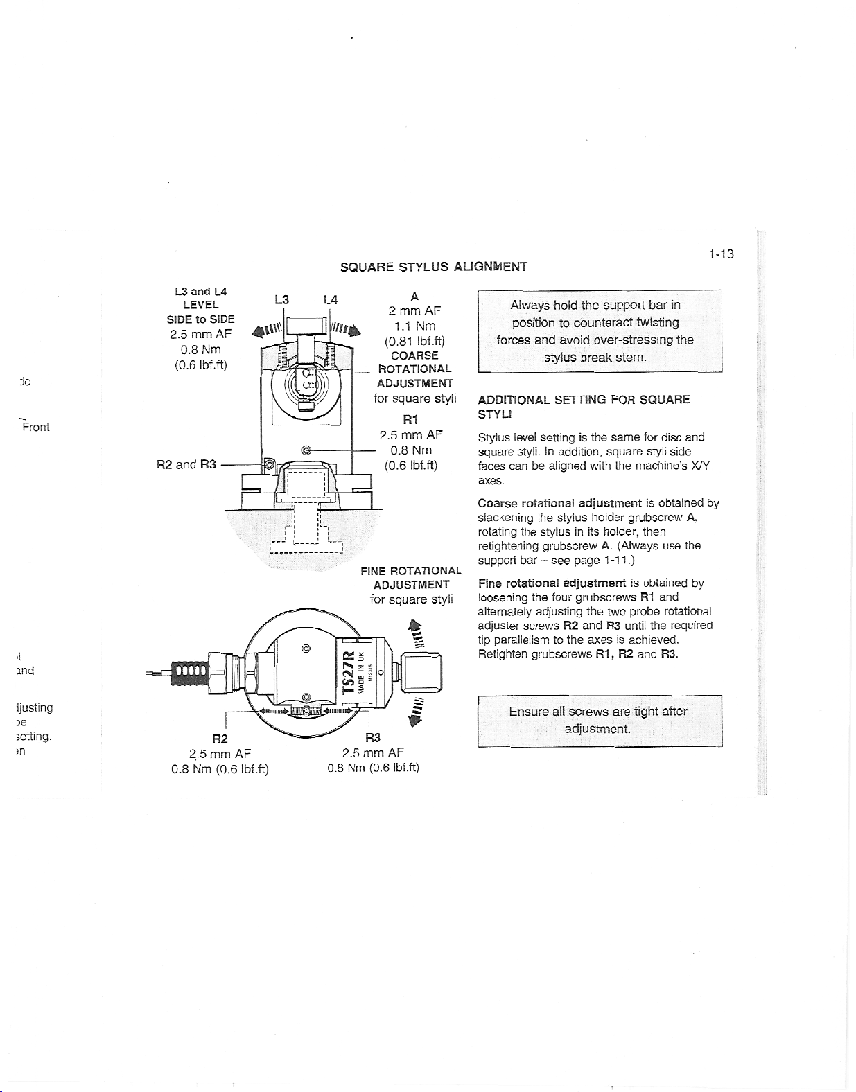
ALIGNMENT
Always
position
forces
ADDITIONAL
STYLI
level
Stylus
styli.
square
can
faces
axes.
Coarse
slackening
rotating
retightening
support
Fine
rotational
loosening
alternately
adjuster
parallelism
tip
Retighten
Ensure
hold
and
stylus
SETTING
setting
In
addition,
be
aligned
rotational
stylus
the
the
stylus
grubscrew
bar
see
-
four
the
adjusting
screws
to
grubscrews
all
support
the
counteract
to
over-stressing
avoid
break
the
is
square
with
adjustment
holder
holder,
its
in
A.
1-11.)
page
adjustment
grubscrews
the
two
the
and
axes
R3
R1,
R2
screws
adjustment.
stem.
FOR
same
the
machine’s
grubscrew
(Always
is
probe
until
achieved.
is
R2
are
tight
bar
twisting
SQUARE
disc
for
styli
obtained
is
then
use
obtained
and
R1
rotational
the
R3.
and
after
1-13
in
the
and
side
X/Y
by
A,
the
by
required
Page 19
1-14
SERVICE
AND
MAINTENANCE
SERVICE
You
may
described
Further
dismantling
equipment
must
be
undertake
in
is
carried
this
handbook.
a
highly
out
the
maintenance
repair
and
specialised
at
authorised
Renishaw
of
operation,
Renishaw
routines
which
Service
Centres.
Equipment
under
warranty
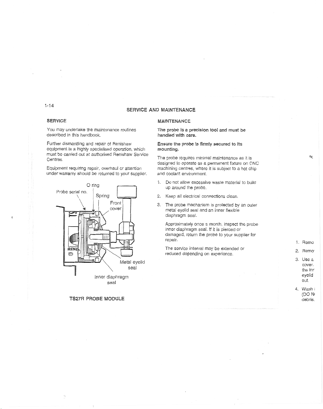
Probe
requiring
serial
should
O
no.
repair,
overhaulorattention
be
returned
ring
Spring
supplier.
your
to
Front
cover
*
I
J
'
REN
I
r5I
a
Metal
eyelid
seal
1
TS27R
Inner
PROBE
diaphragm
seal
MODULE
MAINTENANCE
probe
The
handled
Ensure
mounting.
probe
The
designed
machining
and
coolant
1.
Do
up
Keep
2.
3.
The
metal
diaphragm
Approximately
inner
damaged,
repair.
The
reduced
is
with
the
probe
requires
operate
to
centres,
environment.
not
allow
around
all
electrical
probe
eyelid
diaphragm
service
depending
a
precision
care.
is
firmly
minimal
as
a
whereitis
excessive
the
probe.
connections
mechanism
sea!
and
seal.
once
seal.
return
the
interval
too!
securedtoits
maintenance
permanent
subject
waste
is
protected
an
inner
a
month,
it
is
If
probe
may
be
on
experience.
and
must
fixture
material
clean.
flexible
inspect
pierced
to
your
extended
be
as
a
to
hot
an
by
the
or
supplier
or
on
to
it
is
CNC
chip
build
outer
probe
for
1
.
2.
3.
4.
Remo
Remo1
a
Use
cover.
the
inr
eyelid
out.
Wash
(DO
Ni
debris.
i
Page 20
s
CNC
:hip
jiid
uter
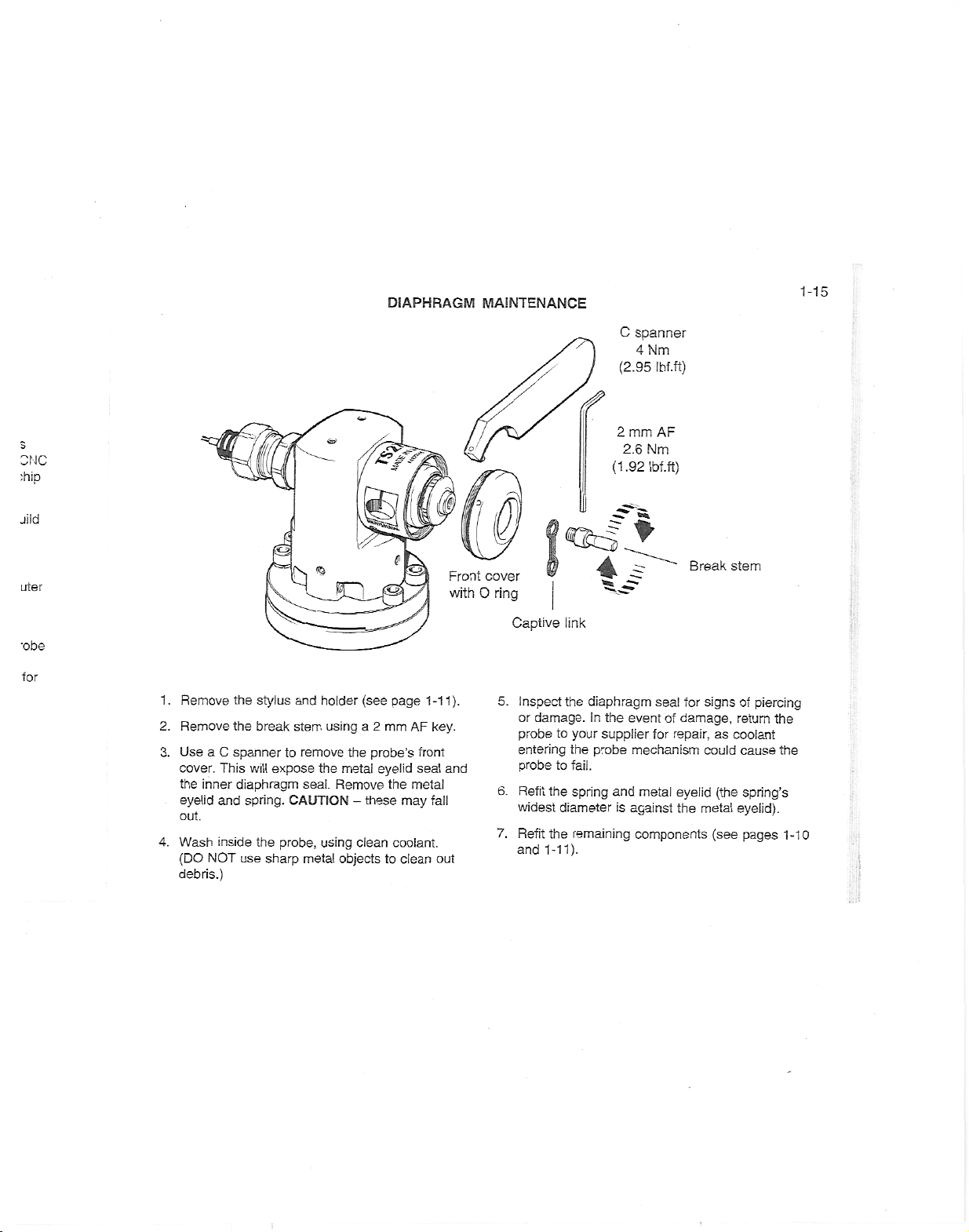
DIAPHRAGM
f)
'TZs'
Front
MAINTENANCE
//
Pi
cover
with
ring
O
C
(2.95
(f
2
(1
«fcf
-4
spanner
4
Nm
mm
2.6
Nm
.92
Ibf.ft)
*
s
Ibf.ft)
AF
Break
1-15
stem
for
.
1
2.
3.
4.
Remove
Remove
a
Use
cover.
the
inner
eyelid
out.
Wash
(DO
NOT
debris.)
the
the
C
spanner
This
will
diaphragm
and
spring.
inside
use
stylus
break
expose
the
sharp
and
stem
to
remove
seal.
CAUTION
probe,
metal
holder
using
the
Remove
using
objects
(see
a
the
metal
-
clean
mm
2
probe’s
eyelid
the
these
to
page
AF
front
seal
metal
may
coolant.
clean
1-11).
key.
and
fall
out
Captive
5.
6.
7.
Inspect
or
damage.
probe
entering
probe
Refit
the
widest
Refit
the
and
1-11).
link
the
diaphragm
In
to
your
the
to
fail.
spring
diameter
remaining
the
supplier
probe
and
is
for
sea!
of
event
mechanism
against
damage,
for
repair,
eyelid
metal
the
components
signs
as
could
(the
metal
(see
of
piercing
return
coolant
cause
spring’s
eyelid).
pages
the
the
1-10
Page 21
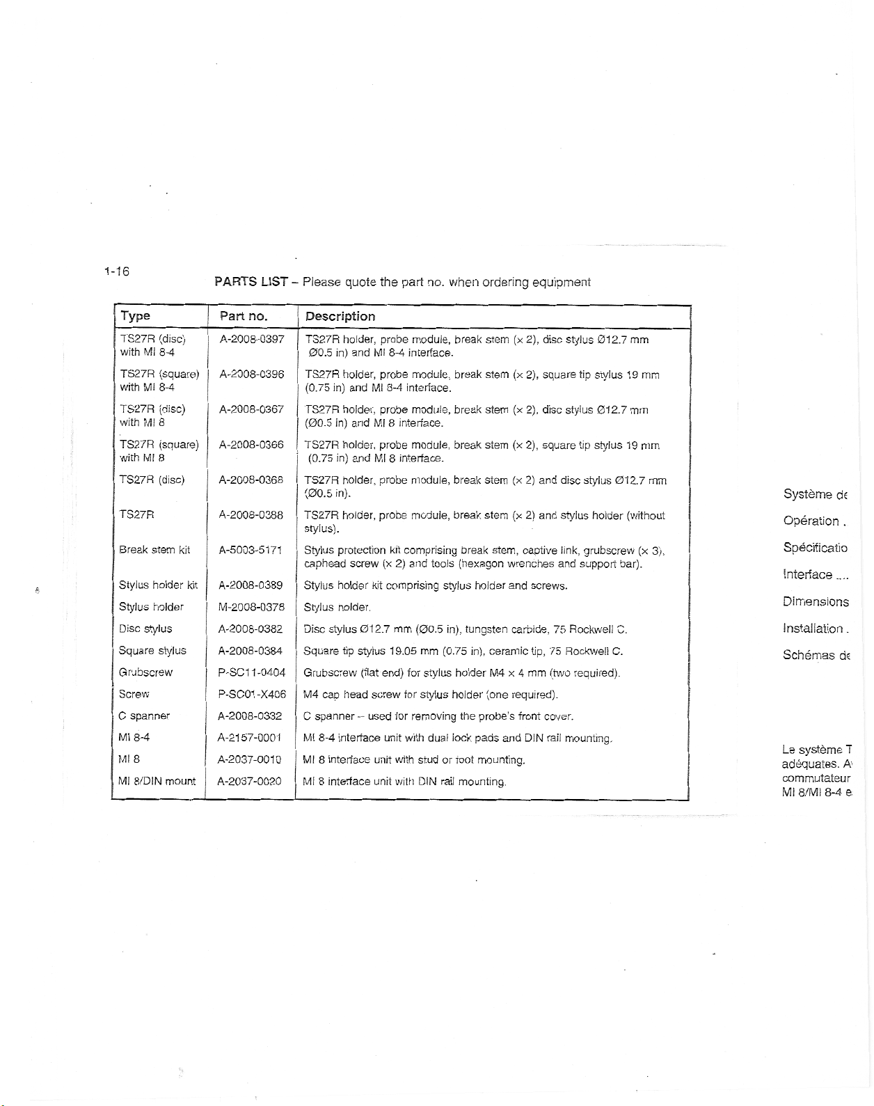
1-16
PARTS
LIST
Please
-
quote
the
part
no.
when
ordering
equipment
Type
(disc)
TS27R
with
8-4
Ml
TS27R
(square)
with
8-4
Ml
TS27R
(disc)
8
with
Ml
TS27R
(square)
8
with
Ml
TS27R
(disc)
TS27R
Break
stem
Stylus
Stylus
Disc
Square
holder
holder
stylus
stylus
*
Grubscrew
Screw
spanner
C
Ml
8-4
Ml
8
Ml
8/DIN
mount
kit
kit
Part
no.
A-2008-0397
A-2008-0396
A-2008-0367
A-2008-0366
A-2008-0368
A-2008-0388
A-5003-5171
A-2008-0389
M-2008-0378
A-2008-0382
A-2008-0384
P-SC1
1-0404
-X406
P-SC01
A-2008-0332
57-0001
A-21
A-2037-0010
A-2037-0020
Description
holder,
TS27R
in)
00.5
TS27R
holder,
(0.75
in)
holder,
TS27R
(00.5
in)
holder,
TS27R
in)
(0.75
holder,
TS27R
(00.5
in).
holder,
TS27R
stylus).
Stylus
protection
caphead
Stylus
holder
Stylus
holder.
Disc
stylus
Square
tip
Grubscrew
cap
head
M4
spanner
C
8-4
Ml
interface
8
Ml
interface
8
Ml
interface
and
and
and
and
screw
012.7
stylus
(flat
used
-
probe
8-4
Ml
probe
8-4
Ml
probe
8
interface.
Ml
probe
interface.
Ml
8
probe
probe
kit
2)
(x
comprising
kit
mm
1
9.05
end)
screw
for
unit
unit
with
unit
with
module,
interface.
module,
interface.
module,
module,
module,
module,
comprising
and
tools
stylus
(00.5
in),
(0.75
mm
for
stylus
stylus
for
removing
dual
with
or
stud
rail
DIN
break
break
break
break
break
break
break
(hexagon
holder
tungsten
in),
holder
holder
probe’s
the
iock
pads
foot
mounting.
mounting.
stem
stem
stem
stem
stem
stem
stem,
ceramic
M4
(one
and
disc
(x
2),
(x
square
2),
(x
2),
disc
(x
2),
square
(x
2)
and
2)
(x
and
captive
wrenches
and
screws.
carbide,
tip,
x
mm
4
required).
front
cover.
DIN
stylus
stylus
disc
stylus
link,
and
75
Rockwell
75
(two
rail
mounting.
012.7
stylus
tip
012.7
stylus
tip
stylus
holder
grubscrew
support
Rockwell
required).
1
19
012.7
(without
bar).
C.
C.
mm
9
mm
(x
mm
mm
mm
3),
Systeme
Operation
cte
.
Specificatio
Interface
Dimensions
Installation
Schemas
Le
adequates.
commutateur
Ml
systeme
8-4
8/MI
ds
A'
.
T
e.
Page 22
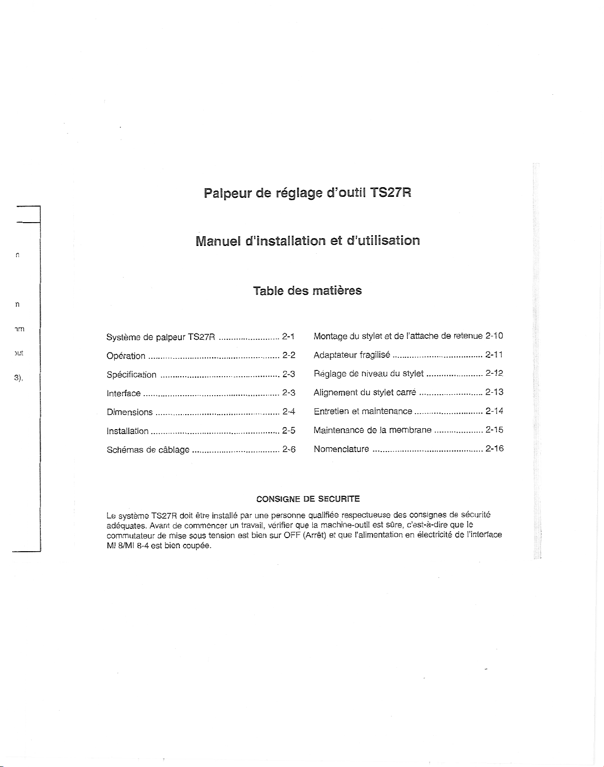
reglage
Palpeur
Manuel
n
n
de
d'lnstallatlon
Table
des
d’outil
et
matieres
TS27R
d'utilisation
im
jut
3),
Systeme
de
Operation
Specification
Interface
Dimensions
Installation
systeme
8/MI
8-4
de
Schemas
Le
adequates.
commutateur
Ml
palpeur
cablage
TS27R
Avant
de
bien
est
TS27R
doit
commencer
de
sous
mise
coupee.
etre
installe
tension
par
un
est
CONSIGNE
une
travail,
bien
2-1
2-2
2-3
2-3
2-4
2-5
2-6
personne
verifier
OFF
sur
Montage
Adaptateur
Regiage
Alignement
Entretien
Maintenance
Nomenclature
SECURITE
DE
qualifiee
la
machine-outil
que
(Arret)
du
de
et
respectueuse
que
I’alimentation
et
stylet
[’attache
de
et
fragilise
du
niveau
du
stylet
maintenance
stylet
carre
delamembrane
consignes
des
c’est-a-dire
sure,
est
en
de
...
electricite
retenue
de
securite
le
que
de
I’interface
2-1
2-11
2-12
2-13
2-14
2-15
2-16
0
Page 23
1
©
995-2005
Ce
document
reproduit
autre
moyen
Renishaw.
publication
La
document
responsabilite
de
Renishaw
Limites
efforts
Des
contenu
d’omissions.
garantie
particulier
Renishaw
b
changements
presentes
quiconque.
Garantie
Tout
equipement
reparation
fournisseur.
Renishaw,
reglage
auraient
N°
de
Revisee
Renishaw
integralement
support
ce
que
ne
degage
pic.
de
garantie
importants
ce
de
Cependant
concernant
reconnaTt
ne
se
reserve
pages
quelconque
L’utilisation
au
meme
effectues
pour
effet
piece
Renishaw
:
peut
ne
ou
dans
soit
sans
des
informations
egard
en
document
le
au
document
sans
sous
titre
par
d’annuler
pic.
Tous
en
aucun
en
ou
partie,
un
autre
I’autorisation
pas
I’utilisateur
droits
aux
ont
ete
soit
depourvu
Renishaw
contenu
aucune
le
droit
d’apporter
et
obligation
garantie
doit
etre
abusive
qu’une
personnes
des
cette
:
H-2000-501
04.05
reserves.
droits
etre
ou
copie
transfere
cas
langage,
prealable
contenues
mis
sa
de
conferes
ceuvre
en
d’erreurs
n’offre
ce
de
document
garantie
au
necessitant
reexpedie
d’equipements
produit
d’en
implicite.
des
decrit
informer
reparation
non
garantie.
8-06-D
ou
par
quelque
ecrite
ce
dans
aux
brevets
pour
aucune
et
dans
une
au
ou
un
qualifiees,
sur
que
et
en
Modifications
Renishaw
specifications
un
Machineacommande
de
Uexploitation
confiee
conformer
Entretien
Maintenez
raisonnable.
le
Marques
RENISHAW®
logo
RENISHAW
Renishaw
apply
Tous
dans
innovation
les
ce
les
marques
deposees
Avis
de
caracteristiques
Les
manuel
apparentes,
brevets
4413968
DE
EP
0293036
EP
0695926
EP
0748669
EP
1051668
des
se
reserve
ses
de
machines-outils
de
personnes
des
a
aux
instructions
du
systeme
les
composants
fabrique
de
et
I’embleme
Royaume
pic
au
noms
autres
document
service,
de
de
leurs
brevet
d’utilisation,
assujetties
sont
ci-dessous
GB
IT
JP
JP
JP
appareiis
ie
droit
produits
numerique
qualifiees,
de
palpeur
des
sont
est
une
marques
de
des
sont
marques
proprietaires
produits
des
ainsi
que
:
2277593
1273643
1,445/1997
2,098,080
320,394/1994
de
modifier
sans
CNC
fabricant.
du
un
dans
capteur
de
marques
Uni
et
marque
marques
de
respectifs.
presentes
celles
aux
brevets
preavis.
doit
qui
devront
etat
utilisee
deposees
dans
Renishaw
de
de
et
de
fabrique
des
JP
US
US
US
US
les
toujours
de
etre
se
proprete
dans
de
d’autres
pays.
pic.
produits
utilises
commerce,
ou
marques
dans
ce
produits
et
depots
de
2002-531,839
5,446,970
5,647,137
5,669,151
6,470,584
B1
I
1
Comm;
CN(
Le
I
I
palpt
le
machine
numeriq
Pour
m«
d’outil,
c
outils
ro
Y
poi
et
c
Les
vis
sur
a
les
L’interfar
le
palpei
Page 24

•s
etre
3
ete
Ians
le
pays.
pic.
'
s
utilises
erce,
larques
SYSTEME
PALPEUR
DE
TS27R
Reglage
2-1
de
diametre
voter
pi
Interfaces
possibles
Us
Cable
RSSKSBS*
as®
Ml
RENISHAW,
m
Ml
i
yas
8-4
8
I
i
i’
Commande
CNC
le
!
I
°
Interface
f.
Pi
O
©
Interface
™
S™"*"
Palpeur
10
7
TS27R
7
9
5V
H
f
Z
=
v
X/Y
4
—•
8
table
Faire
I’outil
sens
2
3
6
RainureaTde
machine-outil
de
dans
contraire
/
m
le
3
3
its
>31
970
137
151
584
ce
de
,839
B1
palpeur
Le
machine
numerique.
Pour
d’outil,
outils
et
Les
sur
mesurer
Y
pour
vis
les
universelle
on
rotatifs
de
axes
L’interface
le
palpeur
TS27R
des
accoste
peuvent
decalages
les
reglage
de
sert
la
et
au
sert
d’usinage
longueurs
stylet
le
etre
de
permettent
machine.
la
traitement
au
commande
reglage
a
d’outils
selon
regies
rayon
d’aligner
des
CNC.
d’outils
commande
ou
un
Z.
les
sur
d’outil.
signaux
Les
axes
le
I’axe
sur
bris
stylet
entre
Stylet
1.
stylets
socle
du
du
stylet
du
du
a
palpeur
-
stylet
stylet
de
de
pour
retenue
fragilise
frontal
du
niveau
des
des
gaine
de
axes
axes
2.
Porte-stylet
3.
Attache
Adaptateur
4.
5.
X
Couvercle
Vis
6.
7.
Reglage
Alignement
8.
9.
Alignement
1
0.
Adaptateur
d’attache
disque
ou
vis
carre
carre
de
carres
reglage
vis
-
vis
-
de
de
reglage
blocage
Page 25

2-2
TOLERANCES
Les
tolerances
dependent
regiage
une
gauche
touche
s’obtient
touche
dans
deiatouche
valeur
-
du
faciiement
carree.
la
plupart
VITESSE
PRECONISEE
pivoter
Faire
oppose
Premier
delamachine
La
contre
d’une
La
1
024
Lutilisation
a
maintenir
a
contact
rotation
le
vitesse
vitessedela
tr/min
50
mm
mm
24
DE
de
de
la
planeite
d’equilibrage
droite
de
stylet,
et
Un
des
D’AVANCE
outils
les
ia
direction
-
en
tr/min
stylet
du
coupe
de
broche
tr/min
et
800
0127
d’outils
superieur
une
vitesse
mm.
a
ou
PARAMETRAGE
parametrage
du
pm
5
parallelisme
un
avec
regiage
parallelisme
du
et
styiet.
On
longitudinal
la
partie
sur
axes
les
d’une
applications
D’OUTIL
tourner
a
coupe.
de
la
en
doit
pour
tourner
127
a
coupe
de
en
premiere
calcule
se
surface
etre
des
d’un
mm
rotation
de
palpeur
a
POSSIBLES
des
outils
obtient
d’equilibrage
et
plate
5
de
stylet
d’un
telle
precision
regiage
de
ROTATIF
dans
le
tr/min
de
manipulation
en
de
60
maintenue
a
outils
diametre
ne
permet
constante.
du
faciiement
de
la
pm
a
d’outils.
sens
la
broche
fonction
m/min.
entre
tourner
inferieur
pas
OPERATION
Premier
machine
La
f
=
f
=
Second
suffit
machine
Vitesse
PROGRAMMES
Les
d’outil
divers
sur
machine-outil).
de
de
contact
d’avance
vitesse
x
tr/min
0,16
x
tr/min
0,12
contact
d’avance
programmes
sont
disponibies
controleurs
demande
-
vitesse
unites
f
f
unites
vitesse
-
800
LOGICIELS
logiciels
de
aupres
ou
d’avance
(f)
calcule
se
mm/min
mm/min
d’avance
tr/min,
4
mm/min.
prevus
aupres
de
machine
(iiste
du
constructeurdevotre
de
comme
(regiage
(regiage
de
les
pour
Renishaw
jour
a
ia
suit
:
diametre)
longueur)
la
reglages
pour
disponible
Sens
de
Repetabiliti
unidirectio
Force
de
du
stylet
Temperatu
Fonctic
Stocka
Valide
*
480
mm
Stylet
a
Carbure
Rockw
75
012,7
mn
K
IP
Adaptatei
fragilis
po
d
a
d
c
S
Page 26

imetre)
igueur)
jlages
jour
iponible
otre
SPECIFICATION
Sens
de
pose
Repetabiiite
unidirectionnelie
Forcededeclenchement
stylet
du
Temperature
Fonctionnement
Stockage
Vaiide
*
480
mm/s
Stylet
Carbure
Rockwell
75
012,7
Ip°
Adaptateur
fragilise
s
avec
a
disque
de
mm
un
sur
le
tungstene,
C.
x
mm
8
BQJ
Attache
stylet
centre
|
—
i
Porte-
stylet
de
012’7
8
35
de
de
retenue
Normalement
dans
palper
±X,
±Y,
-Z
Moyenne
pm.
1
2
1
en
entre
entre
I’embout
Stylet
Touche
75
19,05
sigma
a
N
,3
fonction
+5
-10
mm,
vitesse
carre
Rockwell
mm
(2cr)
2,4
°C
°C
de
ceramique,
x
M
installe
sens
le
machine.
de
la
maximale
*
30
1
N
/
sens
du
et
°C
60
°C
70
et
d’accostage
stylet.
C.
mm
19,05
19,05
des
gf
de
pour
axes
a
240
pose
x
8
19,05
8
gf
mm
Ml
description
d’utilisation
description
autre
interface
le
dans
H-2000-5015.
[.’interface
standard
“skip”.
une
et
Toutes
pour
Linterface
fonction
dispositif
palpeur
de
L’interface
avec
statut
contact
Relay),
interrupteur
Courant
Tension
Une
ainsi
d’une
manuel
La
tension
30
CC.
V
les
fonctionner
‘interdiction’
de
controle.
fonction
la
du
flottant
a
maxi.
maxi.
fonction
qu’un
LED
avec
sortie
entrees
integre
simpiifiant
reglage
palpeur
logique
externe
INTERFACE
I’objet
8-4
fait
integrale
dans
H-2000-5008.
integrale
Ml
comprise
de
possible,
d’utilisation
utilisee
est
8-4
la
fonction
palpeur
entre
sont
en
logique
egalement
ainsi
selection
ia
d’outil
utilisee
8
Ml
est
G31
et
est
disponible
de
type
inversable
(SW1).
mA
50
V
±
50
d’interdiction
dispositif
de
d’etat
d’une
manuel
le
Une
est
Ml
fournie
I’interface
vous
en
et
I’option
G31
fonctionne
V
4,75
configurables
1
ou
0.
une
qu’un
du
du
palpeur
ou
standard
en
t’option
“skip”.
sur
(Solid
SSR
un
via
(Crete)
(crete)
est
incluse,
commande
palpeur.
du
2-3
8,
avec
CC
Le
un
state
Page 27

2-4
DIMENSIONS
dimensions
en
mm
MONTAGE
OUTIL
1
.
machine-i
2.
et
3.
Installer
Renishaw
4.
Serrer
du
5.
Remonter
Serrer
reglage
stylet
6.
Installer
GOUPILLES
Dans
rainure
deux
peuvent
demonte,
Spirol®,
de
fagon
du
palpeur.
remonter
CABLE
Cable
polyuretnanne
cable
(
jaune
centre
.1
Quatre
(deux
les
Z
X/Y X/Y
H
a
J
1
PCD
soni
uns
DEPLACEMENT
Z
H
a
i
IF
054
053,5
pour
trous
utilises)
des
autres
minimum
10°
tous
confondus
STYLET
f
Deux
goupilie
0
1
3
de
MINIMUM
goupilie
equidistance
a
sur
axes
LO
5
i
trous
Spirol®
6,13
5,95
x
profondeur,
Spirol®
054
PCD
X/Y
pour
DEPLACEMENT
5,5
au
stylet
du
co
co
w
o'
o
aaaia
ADAPTATEUR
DE
Y
GAINE
50
?
E
.
7
I—
t
_
i
Sr
i
'!
56
PIVOT
STYLET
a
I
TABLE
27
DU
DE
I
Hill
8
'
7
1
MACHINE-OUTIL
1"
s
ENSEMBLE
A
Diametre
BOULON
par
fournir
du
L2
L1
:
II
m
POUR
RAINURE
I’utilisateur
boulon12maxi.
3!
1
AT
45°
GOUPILLE
SPIROL®
r&
<zC
liRi
IB
o
cb
Choisir
Separer
L1
a
palpeu
(voir
des
aT
goupilles
etre
puis
percer
a
le
quatre
a
4,4
mm.
et
vert
t
I’e
l<
I's
u
le
dei
Li
le
circc
sir
ce
Pla
so
t
!
ir
r
Page 28

INSTALLATION
2-5
JT
X/Y
urn
s
is
7
5
is
pour
Spiral®
3
5
dndeur,
IUM
pirol®
tance
054
MONTAGE
OUTIL
1.
2.
3.
Installer
Renishaw).
4.
du
5.
Serrer
reglage
stylet
Installer
6.
Choisir
I’emplacement
machine-o
Separer
L1
I’aide
a
et
Serrer
le
palpeur
Remonter
deux
L1
(voir
le
DU
un
GOUPILLES
Dans
des
circonstances
a
goupilles
percer
fagon
palpeur.
quatre
a
T
suffisent
etre
puis
a
ce
Placer
le
socle
rainure
deux
peuvent
demonte,
Spiral®,
de
du
remonter
CABLE
Cable
polyurethanne
4,4
cable
(
jaune
mm.
et
vert
PALPEUR
du
util.
le
socle
du
palpeur
d’une
c!easix
boulon
pour
pour
boulon
a
palpeur
le
vis
et
pages
stylet
SPIROL®
Spiral®
installees
remonte.
deux
qu’ils
fils
blinde
Circuit
non
rainure
la
tabledemachine-outil.
sur
a
fond.
H
L2
avant
2-12).
(voir
les
(voir
normales,
pour
bloquerlepalpeur.
(incluses
lorsque
Pour
danslatable
trous
coincident
les
goupilles
du
palpeur.
7/0,2
mm
de
10
de
palpeur
utilises).
SUR
TABLE
palpeur
en
retirant
pans
rainure
a
T
son
socleetinstaller
pas
Ne
d’effectuer
pages
page
2-4)
les
dans
TS27R
le
installer
avec
Spiral®
a
gaine
de
long.
m
-
fils
DE
sur
la
de
4
(non
T
a
fixer
pour
serrer
I’alignement
2-10
et
boulons
le
kit
doit
les
goupilles
de
deux
trous
dans
isolante
Diametre
rouge
MACHINE-
tabledela
les
deux
vis
mm.
pas
fourni
le
socle
vis.
les
les
vis
de
du
2-11).
pour
Ceci
dit,
de
palpeur)
etre
machine-outil
du
socle
les
trous
de
du
bleu
et
RALLONGE
Longueur
Palpeur
Cable
H
polyurethanne
des
GAINE
Renishaw
Betts
installations
TS27R
011
et
REMARQUE:
Le
condensateur
prevenir
blindage
I’interface.
(15
maximale
interface
a
a
deux
branchements.
DE
PROTECTION
preconise
de
Type
confondues.
compatible
est
mm.
Adaptateur
Cable
Gaine
blindage
tout
du
du
risque
cable
m
7/0,2
fils
blinde.
EF
ou
de
cable
de
1
est
maximum)
de
cable
25
m
-
mm
Preserver
le
montage
d’une
Ladaptateur
avec
gaine
n
E
est
connecte
nF
a
00
de
boucle
connecte
authorisee
de
long.
a
gaine
le
CABLE
DU
de
alternative
gaine
une
n
i’interieur
de
terre.
a
I’entree
isolante
blindage
gaines
appropriee,
de
flexible
s
E=
tCNtStttW.
©
H
la
a
machine
du
TS27R
S’assurer
:
de
au
niveau
Thomas
du
gaine
de
par
pour
appropriee
and
toutes
un
que
le
sur
Page 29

2-6
SCHEMA
CABLAGE
DE
TS27R
RECOMMANDE
AVEC
L’INTERFACE
POUR
Ml
LE
8
PALPEUR
COMMANDE
Entree
Jaune/Vert
Active
code
<-
Jaune/Vert
Alimentation
de
I’interface
*
c>
Jaune/Vert
O-
Jaune/Vert
Terre
controleur
CNC
Alimentation
palpage
Blindage
©ÿ
par
M
©ÿ
{
protection
de
£K
+V
0
V
**
E/S
(G31)
c.c.
c.c.
du
»
©
o
©
f
A
xt
FACULTATIF
A
i_L
w
A
Xf
A
•s
•
-®
-©
B7
B6
B5
B1
32
A5
A6
A4
INTERFACE
SSR
SSR
Blindage
inhibition
inhibition
+V
c.c.
V
c.c.
0
Blindage
Ml
Sortie
(sortie
—
statique
j
0
V
ENTREE
}
ALIMENTATION
8
etat
a
palpeur
reiais
SSR)
-
ENTREE
PALPEUR
Pour
des
concernan!
B2
de
Ml
et
les
conn
B3
et
B4,
Putilisateur
r
LED
LED
ir
8
c
////
Terre
de
reference
du
controleur
**
Aussi
“Plaque
appele
de
“PE”
terre”
(Terre
de
protection),
“Point
etoile”
ou
Page 30

2-7
3
etat
a
relais
e
-
ATION
etoile”
palpeur
SSR)
ou
ENTREE
PALPEUR
des
Pour
concernant
de
B2
les
et
B3
B4,
et
I’utilisateur
r
Palpeur+
Palpeur-
Blindage
informations
les
connexions
8
Ml
a
la
connexions
consulter
8
Ml
externe
LED
LED
externe
A1
A2*
A3*
B1
commande
CNC
d’entree/sortie
manuel
le
H-2000-5015.
B3
+
{:
-
B4
MACHINE-OUTIL
DE
D1SPOS1TIF
D’OUTIL
/
>
*
Bleu
Rouge
XI
et
de
I
/
xx
Terre
Le
*
que
alternatif
s’echappent
blindage
potentiel
du
condensateur
controleur
le
courant
<5
/r7i77
de
reference
basse
a
cause
entre
dans
TS27R
PALPEUR
TS27R
Condensateur
100
i
Passage
terre
|
vis
les
I
TS27R
'
100
continu
frequence
le
cable
des
la
terre
celledela
et
REGLAGE
nF*
vers
possible
du
socle
machine
la
de
empeche
nF
etlecourant
du
differences
de
reference
machine.
la
par
du
de
Page 31

2-8
SCHEMA
DE
CABLAGE
TS27R
RECOMMANDE
AVEC
L’INTERFACE
POUR
Ml
8-4
LE
PALPEUR
COMMANDE
+V
c.c.
de
Entree
c.c.
-V
de
Jaune/Vert
I
V
Jaune/Vert
A
Alimentation
(’interface
de
<ÿ
CNC
I’aiimentation
palpage
I’alimentation
Blindage
+V
{
0
V
E/S
(G31
E/S
c.c.
c.c.
e-
)
o-
«.
0-1
&ÿ
9-
A
t7
FACULTATIF
(
I
T
v/
\
\
1
\y
A
V7
-©
-e
-S-
-*
-©
-®
-©
%
Jaune/Vert
e-
-9
Jaune/Vert
Terre
de
controieur
protection
**
du
-®
A1
A1
A12
B4
B5
B6
B7
B8
B9
B10
B11
A7
A8
A9
B1
B2
B3
0
1
SELX-
SELX+
X+
SELZ-
Z-
SELZ+
Z+
Selection
Inhibition
Entree
commune
+V
0
Blindage
INTERFACE
Sortie
isolee+alimentation
Sortie
etat
palpeur
Sortie
isoiee-alimentation
entree
X-
sortie
entree
sortie
entree
sortie
entree
sortie
inspection
resistances,
c.c.
V
c.c.
ENTREE
}
ALIMENTATION
Mi
-
8-4
(montage
en
totem)
ENTRi
PALPEl
Pour
connt
manL
H-201
r
En
En
//S7
Terre
de
reference
du
controieur
appele
Aussi
**
“Plaque
ou
de
“PE”
terre”
(Terre
de
protection),
“Point
etoile”
Page 32

2-9
ition
itage
tion
ON
nt
en
etoile”
totem)
ENTREE
PALPEUR
Pour
des
connexions,
manuel
H-2000-5008
r
Entree
d’inspection+
Entree
d’inspection-
Blindage
_
Palpeur
Palpeur
informations
consulter
de
I’utilisateur
systeme
systeme
Biindage
MACHINE-OUTIL
©ÿ
A1
©-
A2
+
&ÿ
A3
-
sur
le
Ml
A4
A5
A6
ces
8-4
«ÿ
e-
TT
FACULTATIF
A
_
W
Bleu
Rouge
Interface
palpeur
d’inspection
11
\
V7
A
tr
du
*
o
o
Palpeur
d’inspection
DISPOSITIF
Terre
de
Le
condensateur
que
le
courant
alternatif
s’echappent
blindage
potentiel
du
basse
a
entre
controleur
DE
D’OUTIL
-o
PALPEUR
Condensateur
100
-n-
Passage
terre
les
TS27R
/777
reference
continu
frequence
dans
cause
la
terre
et
celledela
REGLAGE
TS27R
TS27R
nF*
possible
vis
de
100
le
cable
des
vers
la
par
du
socle
du
la
machine
nF
empeche
et
le
courant
du
differences
de
reference
machine.
de
Page 33

MONTAGE
DU
STYLET
ET
L’ATTACHE
DE
DE
RETENUE
Stylet
Porte-stylet
:
SERRAGE
suivant
les
vis
d’utiliser
3
retrait
ou
vis
(voir
STYLET
sans
ragiiise
•’UN
maintenu
la
de
dans
tete
mm
2
1,1
DES
les
tige
pieces
page
son
A.
I
i
V
A
AF
Nm
VIS
couples
de
blocage
fixees
2-11).
porte-stylet
2
mm
2,6
Adaptateur
fragilise
indiques
pour
a
par
ie
X
AF
Nm
CJS?'
ATTACHE
en
En
fragilise
emp§che
Lattache
maintient
dans
Lorsqu’une
etre
Attache
retenue
cas
la
pliee
9
de
p?
i\
RETENUE
DE
de
surcourse
se
machine
a
brise
son
d’endommager
de
retenue
ce
dernier
se
et
attache
accepter
pour
excessive
point
le
reliee
car,
sans
perdre.
de
retenue
la
fit
;
&
stylet,
du
le
plus
mecanisme
au
palpeur
eile,
il
est
installee,
C
(voir
vis
faible
de
au
et
pourrait
page
I’adaptateur
ce
qui
palpage.
stylet
tomber
elle
doit
2-11).
T
b
ST
Me
frac
Fail
rete
les
REI
Ret
indi
Page 34

ADAPTATEUR
FRAGILiSE
2-11
laptateur
qui
alpage.
stylet
tomber
elle
doit
-11).
Tige
de
blocage
ET
STYLET
Mettre
fragilise
Faire
retenue
vis.
les
REMPLACEMENT
Retirer
indique
PORTE-STYLET
stylet
le
passer
les
et
installerlavis
et
la
vis
dans
et
precedemment.
le
pieces
B
AF
2
mm
Nm
1,1
porte-stylet
le
sans
au
travers
C
porte-stylet.
L’ADAPTATEUR
DE
cassees
Toujours
les
tete
Cela
remonter
et
forces
I’adaptateur
sur
B
sans
I’attache
de
fait,
tige
la
tenir
de
pivotement
fragilise
du
HS§
4
serrer.
la
de
serrer
toutes
FRAGILISE
I’ordre
suivant
de
stylet
<ci
9
blocage
eviter
et
a
une
REMARQUE
Certaines
etaient
un
avec
uniquement
palpeur
fragilise.
place
en
de
soumettre
force
excessive.
versions
fournies
adaptateur
les
avec
ou
pour
C
-
3
mm
2,6
Nm
anciennes
avec
fragilise
composants
le
kit
compenser
I’adaptateur
'I
/
AF
du
sans
des
vis
different.
actuels
retrofit
de
4
tete
fournis
TS27R
a
pointeau
Installer
palpeur
d’adaptateur
avec
et
ce
.
Page 35

2-12
ATTENTION:
Stylet
L1etL2
H,
4
mm
5
Nm
TYPESDESTYLET
Stylet
a
disque
carre
Stylet
DE
REGLAGE
La
surface
niveau,
Le
niveau
reglage
NIVEAU
superieure
longitudinalement
longitudinaldustylet
des
L1
vis
carre
012,7
19,5
et
mm
du
L2
Vis
L2
mm
x
DU
stylet
et
en
REGLAGE
pas
Ne
Stylet
W/
/
i
L1
a
rondelle
elastique
19,5
mm
STYLET
doit
etre
gauche
de
s’obtient
alternance
soumettre
a
disque
j,
mise
de
a
droite.
le
par
entralne
qui
NIVEAU
DE
I’adaptateur
une
capteur
surface
Le
reglage
une
niveau
plane,
STYLET
DU
fragilise
a
L3
2,5
0,8
L3
$
§
1
ou
modifie
et
du
stylet
gauche
en
alternance
stylet.
les
descente
montee
niveau
rotationdumodule
du
serrer
des
|
est
Une
vis
et
mm
Nm
le
a
forces
L4
_
I
E
niveau
plane,
droite
fois
L3
*
1
des
de
et
L4
n
<QJ
de
que
L4.
excessives
Arriere
Cote
i
cs
rcgp
I’extremite
stylet.
du
les
serrer
stylet
du
L3
vis
et
palpage
la
surface
H
du
Une
vis
L1
s’obtient
L4
qui
et
modifie
du
Cote
cable
fois
et
par
produit
le
stylet
Avant
du
que
L2.
le
la
est
Page 36

ALIGNEMENT
DU
STYLET
CARRE
2-13
2.
Jit
:t
i
ue
du
le
est
H
Ji
II
m
o
L4
'"//£.
-,
Reglage
2S
rÿ.
S|«°
Reglage
rotation
—
approximatif
pour
precision
de
stylet
pour
S
s
z
R3
mm
2.5
Nm
0,8
A
mm
2
1,1
stylet
R1
2.5
0,8
en
ir
LE
Nm
en
carre
mm
Nm
rotation
carre
£>
1
Toujours
en
forces
soumettre
stylet
REGLAGE
STYLET
Les
les
outre,
alignes
Un
s’obtienten
porte-stylet,
porte-stylet,
tete
voir
Le
s’obtient
tete
du
que
rapport
les
CARRE
reglages
memes
les
sur
reglage
(Toujours
A.
page
reglage
en
et
R1
palpeur
le
parallelisme
aux
vis
sans
S’assurer
serrees
tige
la
tenir
compenser
pour
place
pivotement
de
I’adaptateur
force
une
a
SUPPLEMENTAL
de
niveau
du
du
ceux
que
stylet
du
cotes
axes
rotation
faisant
en
.)
1
rotation
reglant
et
que
apres
X/Y
en
resserrant
utiliser
les
R3
en
voulu
soil
R1,
R2
toutes
chaque
la
pivoter
la
les
alternant,
atteint.
les
les
en
desserrant
puis
2-1
en
desserrant
en
R2
axes
tete
blocage
de
les
eviter
et
fragilise
excessive.
POUR
carre
stylet
stylet
de
et
disque.
a
doivent
carre
machines.
des
approximatif
tete
sans
vis
stylet
ie
la
vis
blocage
tige
de
precision
vis
quatre
visderotation
deux
delatouche
Cela
R3.
vis
reglage.
jusqu’a
fait,
sont
de
du
bien
sont
En
etre
A
dans
sans
sans
par
serrer
du
le
-
ce
4
L3
\\\w
Jfc
L3
Niveau
a
2.5
0,8
et
gauche
droite
mm
Nm
L4
Tit
R3
et
R2
u
„j
Hill
la
R2
2.5
mm
Nm
0,8
Page 37

2-14
ENTRETIEN
ET
MAINTENANCE
ENTRETIEN
Les
operations
manuel
Tout
Renishaw
peuvent
demontage
n’y
hautement
etre
confies
agrees.
Tout
materiel
reparation,
specialiste
serie
Nombre
du
RENI
MODULE
doit
palpeur
de
maintenance
etre
effectuees
et
reparation
figurant
specialisees
Centres
aux
garantie
sous
une
revision
renvoye
etre
Joint
torique
de
\
;Jr
M
U
N
T-
1
PALPEUR
DE
decrites
par
du
sont
doivent
materiel
des
par
pas
et
d’Entretien
necessitant
[’attention
ou
au
fournisseur.
Ressort
Couvercle
\ÿfrontale
n?
Membrane
TS27R
dans
I’utilisateur.
operations
consequent
Renishaw
une
d’un
__
1
Joint
bombe
en
metal
d’etancheite
interne
ce
MAINTENANCE
Votre
palpeur
a
ce
de
donne
brOlants
est
pas
avec
que
montage.
qu’il
monte
d’usinage
un
laisser
a
bien
manipuler
Veiller
support
Etant
un
appareil
universelle
copeaux
palpeur
1.
Ne
palpeur.
2.
Veiller
branchements
3.
Le
mecanisme
joint
bombe
d’etancheite
Environ
une
membrane
cas
de
membrane
renvoyer
reparation.
L’experience
d’entretien
le
un
est
outil
precaution.
ie
palpeur
est
congu
en
permanence
a
CNC
dans
un
outil
a
faible
les
debris
maintenir
electriques.
du
palpeur
externe
d’etancheite
palpeur
doit
interne
fois
par
percee
permettra
etre
en
souple.
mois,
au
reduit
de
precision
soit
bien
fixe
pour
fonctionner
sur
soumise
machine
a
des
environnement
maintenance.
s’accumuler
la
proprete
est
protege
metal
et
inspecter
interne
ou
endommagee,
fournisseur
de
decidersiI'intervalle
ou
prolonge.
une
du
des
palpeur.
pour
autour
membrane
ia
a
a
son
comme
refroidi,
par
un
En
du
le
1.
Re
2.
Re
2
n
3.
Util
fror
me
bor
rise
Lav
4.
refr
poir
palf
Page 38

a
son
x
comme
:hine
3
efroidi,
du
utour
un
tar
rmbrane
MAINTENANCE
s
le
I
SJi
DELAMEMBRANE
m
P
f
2
2,6
Cle
mm
4
Nm
en
Nm
AF
C
2-15
lli
<*2c§
'v
J'
Couvercle
avec
frontal
torique
joint
Attache
4
de
*
s
retenue
Adaptateur
fragilise
eur.
En
gee,
itervalie
Retirer
1.
2.
Retirer
mm.
2
3.
Utiliser
frontal,
membrane
bombeetle
risquent
4.
Laver
refroidissement
pointu
palpeur).
stylet
le
I’adaptateur
une
cle
exposer
et
d’etancheite
ressort.
de
tomber.
I’interieur
en
metal
porte-stylet
le
et
fragilise
C
en
le
ATTENTION
du
palpeur,
vierge
pour
avec
pour
demonter
bombeenmetal
joint
interne.
I’aide
a
(NE
PAS
retirer
ies
(voir
une
Retirer
-
utiliser
debris
page
cle
couvercle
le
le
pieces
Ces
de
liquide
un
du
2-11).
de
et
joint
objet
pour
ni
renvoyer
le
et
important
joint
bombe
des
d’etancheite
endommagee.
le
reparation;
pour
refroidissement
de
palpeur
du
joint
bombe
ressort
du
metal).
en
composants
Examiner
5.
qu’elle
de
toute
la
de
I’interieur
entraTner
Remonter
6.
(le
plaque
Reinstaller
7.
2-10
la
membrane
percee,
ni
n’est
deterioration,
penetrationdeliquide
du
mecanisme
son
dysfonctionnement.
ie
ressort
contre
le
2-11).
le
reste
plus
le
diametre
et
En
pourrait
metal
en
se
pages
(voir
verifier
cas
a
Page 39

2-16
NOMENCLATURE
-
veuiliez
indiquer
la
reference
des
pieces
a
la
commande
Type
TS27R
(disque)
avec
TS27R
avec
TS27R
avec
TS27R
avec
TS27R
8-4
Ml
(carre)
8-4
Ml
(disque)
8
Ml
(carre)
Ml
8
(disque)
TS27R
Kit
d’adaptateur
fragilise
A
Kit
porte-stylet
de
Porte-stylet
Stylet
disque
a
carre
Stylet
Vis
sans
tete
Vis
en
Cle
C
8-4
Ml
Ml
8
8/montage
Ml
DIN
Reference
A-2008-0397
A-2008-0396
A-2008-0367
A-2008-0366
A-2008-0368
A-2008-0388
A-5003-5171
A-2008-0389
M-2008-0378
A-2008-0382
A-2008-0384
P-SC1
1-0404
P-SC01-X406
A-2008-0332
57-0001
A-21
A-2037-001
A-2037-0020
0
Description
sans
TS27R,
mm
TS27R,
19
TS27R,
mm
TS27R,
19
TS27R,
mm.
TS27R,
stylet).
du
tete
du
Support
012,7
Support
carree
Support
012,7
Support
carree
Support
012,7
Support
(sans
Pieces
vis
Pieces
Porte-stylet.
a
Stylet
disque
Stylet
touche
a
sans
Vis
Vis
CleenC
interface
Interface
Interface
tete
a
tete
-
Ml
Ml
Ml
et
mm
et
mm
kit
kit
M4
outil
8-4
8
8
module
interface
module
interface
et
module
interface
module
et
interface
module
module
de
protection
(x
3),
vis
de
porte-stylet
012,7
carree,
(plate)
pour
porte-stylet
de
avec
avec
avec
palpeur,
Ml
8-4.
palpeur,
Ml
palpeur,
8.
Ml
palpeur,
M!
palpeur,
palpeur,
du
tete
a
:
mm,
carbure
19,05
porte-stylet
pour
demontage
deux
tampons
goujon
filete
montage
adaptateur
adaptateur
8-4.
adaptateur
adaptateur
8.
adaptateur
adaptateur
:
stylet
(x
2)
et
outils
porte-stylet
de
mm,
touche
est
(une
couvercle
du
de
montage
ou
rail
sur
DIN.
fragilise(x2),
fragilise(x2),
fragilise
fragilise(x2),
fragilise
fragilise
adaptateur
(cles
vis.
et
tungstene,
ceramique,
x
mm
M4
4
necessaire).
frontal.
verrouillage
sur
fragilise,
a
6
pans
75
Rockwell
(deux
et
pieds.
(x2),
(x
2)
(x
2)
attache
et
Rockwell
75
sont
montage
stylet
disque
a
stylet
a
touche
a
stylet
disque
a
stylet
touche
et
a
stylet
et
porte-stylet
de
de
tige
blocage).
C.
C.
necessaires).
sur
rail
disque
retenue,
DIN.
Messts
Betriefc
Spezifi
Interfa
Abmes
instalic
Verdra
IV
Das
maBn;
Ausga
ausge
Page 40

ue
he
ue
he
TS27R
Werkzeugmess-System
Installations-
Benutzerhandbuch
und
Werkzeugeinstellung
zur
i
Inhaltsverzeichnis
;que
t
enue,
>ge)-
-)•
>IN.
Messtastersystem
Betriebshinweise
Spezifikation
interfaceversionen
Abmessungen
Installation
Verdrahtungsschema
Messtastersystem
1!
Das
maBnahmen
Ausgangsstellung
ausgeschaltet
TS27R
installiert
befinden
sein.
8/MI
Ml
TS27R
werden.
und
8-4
nur
darf
Arbeitsbeginn
Vor
Versorgungsspannung
die
3-1
3-2
3-3
3-3
3-4
3-5
3-6
SICHERHEITSHINWEIS
geschultem
von
Montage
Sollbruchstuck
Tastereinsatz
Tastplatte
Service
Wartung
Teile-Liste
Personal
muss
sich
Tastereinsatz
ausrichten
ausrichten
und
Wartung
der
Dichtung
unter
Werkzeugmaschine
die
der
Maschine
Einhaltung
und
Sicherungsband
und
.
.
bekannter
das
fur
in
einer
interface
....
3-10
3-11
3-12
3-13
3-14
3-15
3-16
Sicherheits-
gesicherten
muss
Page 41

©
1
995-2005
Dieses
Genehmigung
teiiweise
irgendeine
andere
Die
Veroffentlichung
bedeutet
Renishaw
Haftungsausschiuss
Es
wurden
unternommen,
dieses
Dokuments
Renishaw
den
inhalt
jede
abgeleitete
sich
das
und
dem
ohne
die
Giber
solche
Garantie
Bei
Garantieanspriichen
t
Lieferanten
konnen
wenn
die
eingesetzt
autorisiertem
Renishaw
Dokument
von
kopiert
Weise
Sprache
dass
nicht,
pic.
betrachtliche
urn
ubernimmt
dieses
Gewahrleistung
vor,
Recht
darin
beschriebenen
Verpflichtung
Anderungen
zuruckgesandt
gegenuber
Ausrustung
bzw.
Reparaturen
Personal
darf
Renishaw
Oder
auf
andere
ubertragen
von
es
sicherzustelien,
vollstandig
jedoch
Dokumentes
Anderungen
Renishaw
nicht
Renishaw-Bestell-Nr.:
Veroffentlicht:
04.05
Alle
pic.
ohne
vervielfaltigt
Rechte
vorherige
weder
werden
ganz
Medien
werden.
Materialindiesem
von
frei
ist
Patentrechten
Anstrengungen
dass
fehlerfrei
und
Gewahrleistung
keine
und
lehnt
ab.
Renishaw
an
diesem
Produkt
einzugehen,
zu
muss
werden.
irgendeine
informieren.
die
Ausrustung
Keine
geltend
bestimmungsgemaB
Oder
durchgefuhrt
H-2000-501
Justagen
wurden.
8-06-D
vorbehalten.
schriftliche
noch
Oder
Oder
in
eine
Dokument
Inhalt
der
ist.
insbesondere
Dokument
vorzunehmen,
zum
Anspruche
gemacht
werden,
von
auf
der
fur
behalt
Person
nicht
Anderungen
Renishaw
Ausrustung
behalt
der
sich
ohne
Ausrustung
Ankundigung
CNC-Maschinen
CNC-Maschinen
Herstelleranweisungen
werden.
bedient
des
Pflege
Messgeratekomponenten
Die
miissen
Mess-Systems
werden.
Warenzeichen
RENISHAW®
RENISHAW
Renishaw
anderen
apply
der
Renishaw
in
Alle
Produktnamen
Dienstleistungsmarken,
eingetragene
sowie
sind
pic
im
Landern.
innovation
pic.
diesem
Warenzeichen
registrierte
Verelnigten
ist
Dokument
sind
Handelsbezeichnungen,
Patente
Merkmale
gezeigten
durch
und
Funktionen
Produkte
nachfolgende
und
Patente
geschutzt:
DE
EP
EP
EP
EP
4413968
0293036
0695926
0748669
1051668
GB
IT
JP
JP
JP
die
Spezifikation
vor,
gema(3
stets
zu
von
mussen
das
Tastersymbol
Warenzeichen
Konigreich
ein
eingetragenes
verwendeten
Warenzeichen
ihrer
derindiesem
ahniicher
und
2277593
1273643
1,445/1997
2,098,080
320,394/1994
andern.
der
den
geschultem
sauber
Logo
im
und
Personal
gehalten
von
von
in
Warenzeichen
Marken-
Oder
jeweiligen
und
Besitzer.
Handbuch
Messgerate
Patentanmeldungen
JP
US
US
US
US
sind
2002-531,839
5,446,970
5,647,137
5,669,151
6,470,584
B1
Kabe
I
I
CNC-
Maschinen-
steuerung
I
I
Der
Messtasti
zentren
Fur
das
gegen
zur
die
Lange
Werkzeuc
den
Ta
Vi
Fraswerkzeug
Werkzeugradi
Mittels
Justagi
Maschiner
die
Die
Signale
Steuerung
zv
we
verarbeitet.
Page 42

MESSTASTERSYSTEM
TS27R
3-1
;onal
ialten
on
ichen
jnd
tzer.
h
1
jen
1,839
’0
17
11
B1
A
Interface-Varianten
77
0
Kabe!
I
CNC-
Maschinen-
steuerung
I
Der
Messtaster
zentren
Fur
das
gegen
zur
Werkzeugeinstellung
die
Langenmessung
Werkzeug
Tastereinsatz
den
Fraswerkzeugen
t
®
°
Mi
TS27R
in
der
konnen
Ml
l-V
8-4
THRENISKAW,
8
Interface
Spindelachse
Werkzeugradiuskorrektur
Mittels
Justageschrauben
die
Maschinenachsen
Die
Signale
Steuerung
werden
zwischen
ausgerichtet
Messtaster
von
einer
verarbeitet.
-aSsansj
m
ar.ara:
Interface
k.®
m-
wird
an
CNC-Bearbeitungs-
und
Bruchkontrolle
gefahren.
die
Achsen
abgeglichen
kann
der
Interfaceeinheit
7
eingesetzt.
(Z-Achse)
Bei
X
und
werden.
Messtaster
werden.
CNC-
und
Y
wird
zur
auf
TS27R
10
m
7
Messtaster
7
9
<9
.
1
T
astereinsatz
2.
Halter
fur
3.
Sicherungsband
4.
Sollbruchstuck
5.
Frontring
6.
Befestigungsschrauben
7.
Justierschrauben
8.
Justierschrauben
9.
Klemmschrauben
10.
Schutzschlauch-Verschraubung
Z
V
5
X/Y
?
iESi
j
Tastscheibe
fur
fur
fur
4
Tastereinsatz-Ausrichtung
Tastplatte-Ausrichtung
Tastplatte-Ausrichtung
Radiuskorrektur
Werkzeug
ruckwarts
'‘••V/ji"
1
2
3
6
Maschinentisch
T-Nuten
Oder
Tastplatte
n
dreht
/
*
:
Page 43

Page 44

lit
aus:
ing
:eit
Antastrichtung
Wiederhoigenauigkeit
Antastkraft
Temperaturbereiche
Betrieb
Lagerung
Werte
und
einer
Zentrum
mit
einem
Vorschubgeschwindigkeit
des
Tastereinsatzes
*
Tastscheibe
Hartmetall
012,7
mm
HRC
x
8
75
mm
Ijita
Sollbruchstuck
a
Sicherungs-
band
Tastereinsatz-
halter
SPEZIFIKATION
Bei
vertikalem
Antastung
1
bei
pm
2
1
N
35
,3
abhangig
+5
-10
mm
bis
°C
bis
°C
iangen
2,4
bis
geraden
ermitteit.
Tastplatte
Keramik
19,05
IjHjJt
izi
B
±X,
in
Sigma
von
°C
60
70
von
mm
"
U
Anbau
±Y,
und
(2cr)*
(1
N
30
gf
der
Antastrichtung
“C
Tastereinsatz
480
75.
HRC
x
19,05
19,05
;
geeignet
-Z
bis
240
mm/min
x
8
mm
19,05
i
8
Das
zur
Beaienungsanleitung
ausfOhrlich
Interface
Bedienungsanleitung
gf)
beschrieben.
Das
Standard
eingesetzt.
status
30
Vdc
im
Eingange
Alle
ACTIVE
Daruber
„Sperrfunktion“
eine
Werkzeugeinstell-
Ml
Das
G31
Das
Messtastersignal
potentialfreien
Steuerung
Schalter
max.
max.
Eine
zum
Status-LED
INTERFACEVERSiONEN
Ml
8-4
Interface
beschrieben.
wird
ausfuhrlich
in
wird
H-2000-5008
Das
in
H-2000-5015
8-4
Ml
Interface
G31
Der
kann
zwischen
arbeiten
HIGH
hinaus
einfache
SKIP
Auswah!
8
Interface
Steuerungseingang
weitergeleitet.
(SW1)
Ausgangsstrom
Spannung
Sperrfunktion
Betrieb
einer
sind
wird
SKIP
Steuerungseingang
Ausgang
des
4,75
(Gleichstrom).
voil
sind
und
sowie
ACTIVE
bietet
konfigurierbar
das
eine
zwischen
und
Spindeimesstaster.
wird
mit
wird
Ausgang
(SSR)
Es
negierbar.
50
±50
sowie
die
externen
ebenfalls
mit
Vdc
Interface
Einrichtung
uber
moglich.
der
8
Ml
der
dem
Messtaster-
und
fur
LOW-Betrieb.
eine
dem
Standard
eingesetzt.
einen
,»i
die
ist
uber
einen
mA
V
Moglichkeit
Messtaster-
3-3
fur
Page 45

3-4
50
lift!
IE
VERSCHRAUBUNG
FUR
ANACONDA
SCHUTZSCHLAUCH
b
T-NUTSTEIN
(nicht
im
Lieferumfang
Max.
SchraubengroBe
r—>
*-
|
ES
-
I—
L2
L1
ig
JEffiLZ
SI
Sf
—
T
enthalten)
M12
]
I
ABMESSUNGEN
56
MESSTASTER
DREHPUNKT
I
S'tP
©
H
I
L
i
-
— —
MASCHINENTISCH
SPANNSTIFT
27
<rS
S
45
(mm)
MONTAGE
Z
UBERLAUFWEG
|
(bezogen
8
Tastermitte)
i
I
5,5
mm
auf
4'V
CO
LO
o'
LJ
1-
<b
cb
z
T
x/Y
X/Y
i
-
—
/
H
I
V
t
Teilkreis
063,5
Vier
Spannstifte
(davon
werden
7
f"*
H
054
Zwei
Bohrungen
auf
X/Y
OBERLAUFWEG
Minimum
jeder
in
TASTEREINSATZ
Spannstifte
fur
06,13
05,95
min.
Teilkreis
zwei
10°
Achse
in
03
.
Bohrungen
mm
mm
13
fief
fOr
054
genutzt)
MASCHINENT;
1.
2.
3.
4.
5.
6.
SPANNSTiFTE
Die
den
TS27R
gunstiger,
Lieferumfang
Locher
zu
bohren.
den
ubereinstimmen
die
Basis
ELEKTRISCHEI
Geschirmtes
am
ist
griin
DE:
Wahlen
Messtaster
Nehmen
Hierfur
Sechskants
Sis
Si
die
T-Nutstein
T-Nutstein
Maschinent
Messtaster
FuBplatte
wird
Taste
3-11).
T-Nuten-Be
normalen
Bohrungen
werden
der
reinss
otter
die
entsprec
Die
wiede
roten
b
Ta
A
gel
5
er
Kal
unc
nici
i
Page 46

EG
0°
gen
fte
I
1
if
i54
tzt)
se
ATZ
DES
MONTAGE
MASCHINENTISCH
Wahlen
1.
Messtaster
Nehmen
2.
Hierfur
MESSTASTERS
eine
Sie
auf
die
Sie
Schrauben
die
Sechskantschlussel
3.
4.
T-Nutstein
T-Nutstein
(nicht
festzeihen,
Maschinentisch
Messtaster
5.
FuBplatte
wird
Tastereinsatz
6.
3-11).
SPANNST1FTE
Die
T-Nuten-Befestigung
normalen
den
TS27R
ofter
gunstiger,
Lieferumfang
entsprechend
Locher
bohren.
zu
Bohrungen
den
ubereinstimmen,
die
Basis
ELEKTRISCHER
Geschirmtes
ist
roten
am
werden
grun
mit
befestigen.
Tastereinsatz
der
(siehe
Anforderungen.
gelost
beiden
die
enthalten)
Bohrungen
Die
in
wieder
Kabel,
blauen
und
nicht
so
montiert
geeignete
Maschinentisch
dem
FuBplatte
und
H
iosen
(siehe
Lieferumfang)
im
die
urn
zu
befestigen.
Schrauben
beiden
montieren
und
den
Mit
justiert
(siehe
3-4)
Seite
Standardbefestigung
als
Wenn
entfernt
zusatzlichen
zu
nutzen.
Skizze
der
Tisch
im
Montagegrundplatte
der
nach
dass
werden
ANSCHLUSS
m
04,4
lang,
10
verwendet).
angeschlossen
Draht
AUF
Position
Messtaster
vom
L1
mit
Seite
FuBplatte
H
Schrauben
(siehe
Seiten
der
werden
Spannstifte
Dazu
den
in
mussen
Einsetzen
kann.
mm.
INSTALLATION
DEM
den
fur
aus.
ab.
4
einem
einlegen.
soli,
Maschinentisch
mm
3-4)
dem
auf
auf
wieder
und
L1
3-12).
Seite
3-10
und
Messtaster
es
ist
(im
zwei
sind
exakt
Spannstifte
der
Tastsignal
Das
(gelb
der
genugt
mit
und
L2
VERLANGERUNG
max.
zulassige
und
interface
muss
Die
Messtaster
Abschirmung
KABELSCHUTZ
Renishaw
und
Hersteller,
genutzt
Messtasters
einem
empfiehlt
Betts
Typ
wie
werden.
TS27R
Durchmesser
H.F.X
sie
Die
Verschraubung
Kabel
Schutz¬
schlauch
HINWEIS:
Kabelschirm
Der
Kondensator
im
TS27R
Spannungsspitzen
Interface
dem
mit
max.)
m
(15
Kabellange
darf
25
angeschlossen
Schutzschlauche
oder
gleichwertige
bei
sonstigen
Verschraubung
Schutzschlauche
nimmt
1
von
mm
1
Schutzschlauch
fur
:
H
F
1
ist
einem
mit
verbunden,
abzuieiten.
zu
verbinden.
zwischen
betragen.
m
werden!
Thomas
von
anderer
Installationen
des
auf.
4ÿ
—
I
P
100
nF
um
Schirm
Der
bis
3-5
Die
zu
ist
Page 47

3-6
CNC
STEUERUNG
VERDRAHTUNGSSCHEMA
TS27R
MIT
8
Ml
INTERFACE
Ml
8
INTERFACE
I/O
Versorgung
Spannungs-
versorgung
fur
o-
<ÿ
<5
Messeingang
Gelb/Grun
M
Befehl
Treiber
Gelb/Grun
Interface
Gelb/Grun
Gelb/Grun
(G31)
Schirm
Sr
&
+V
d.c.
{
0Vd.c>
/Steuerung-Schutzieiter**
©•
A
»
XT
-c-
OPTIONAL
.
_
/-
'
j
©-
A
XT
-•
•
—
-®
B7
B6
B5
B1
B2
A5
A6
A4
SSR
SSR
Schirm
inhibit
Inhibit
+V
V
0
Schirm
0
d.c.
d.c.
Tastsigna!
_
(potentialfreier
SSR-Ausgang)
'
V
Spannungs-
}
versorgung
MESSTASTER-
EINGANG
Mehr
Infori
Sperreings
zum
Anscf
LED
(B3-B
Mi
8-Hand
Externe
Externe
Me
Me
Sc
Kann
////
Steuerungs-Masse
**
sein.
als
„PE“
„Sternpunkt“
Oder
„Masse“
bezeichnet
Page 48

WERKZEUGMASCHiNE
3-7
ar
TS27R
g)
MESSTASTER-
EINGANG
Mehr
Sperreingang
zum
LED
Ml
Messtaster+
Messtaster-
Schirm
Information
Anschluss
(B3-B4)
8-Handbuch
finden
zum
B1
und
einer
H-2000-5015
1
Externe
Externe
LED
LED
B3
+
B4
-
A1
A2
A3@-
B2
externen
Sie
im
{:
*ÿ
*-
und
r
7
1
Blau
Rot
A
tr
TS27R
Messtaster
-c
i
Masseverbindung
erfolgt
|
Befestigungs-
schraube
;
c
S777
nF
100
Kondensator
uber
die
des
TS27R
*
Maschinen-Masse
Der
*
100
nF
Kondensator
Storspitzen
Potential-Ausgleich
Maschine
ab
und
bzw.
Steuerung
leitet
bringt
einen
zwischen
Page 49

3-8
VERDRAHTUNGSSCHEMA
TS27R
MIT
Ml
8-4
-S
-®
-©
-6
-e
-®
-e
-&
-®
©
-®
&
Ml
8-4
INTERFACE
A10
+V
(Versorgung
1
Ausgang
A1
-V
A12
B4
B5
B6
B7
B8
B9
B10
B11
A7
A8
A9
B1
B2
B3
(Versorgung
SELX-
X-
SELX+
x+
SELZ-
Z-
SELZ+
Z+
Spindeimesstaster
Sperreingang
fur
OV
Ein-/Ausgange
d.c.
+V
d.c.
OV
Schirm
Oder
fur
Tastsignal)
Tastsignal
fur
Tastsignal)
Eingang
Ausgang
Eingang
Ausgang
Eingang
Ausgang
Eingang
Ausgang
\
Spannungsversorgung
fur
J
,,
Masse"
Ml
8-4
bezeichnet
(1
5-30
V
d.c.)
sein
MESSTASTER¬
EINGANG
"
Mehr
Sie
im
H-2000-5
r
Eingang
Spindei-
messtaster
fur
Sch
Mes
Mes
Infc
M
i
Einc
Einc
Sch
CNC
STEUERUNG
d.c.
+V
Versorgung
Messtastereingang
-V
d.c.
Versorgung
Gelb/Grun
Tastsignal
(G31)*-
Tastsignal
Schirm
•-
©-
_
xt
OPTIONAL
A
O'
\J
\J
Gelb/Grun
Spannung-
versorgung
y
*
i
Interface
+V
{
OVd.c>
Gelb/Grun
<ÿ
Gelb/Grun
-o
Gteuerung
Schutzleiter
d.c.
**
&
**
Kann
als
„Sternpunkt“
„PE“
////
Steuerung-Masse
Page 50

3-9
astsignal)
istsignal)
arsorgung
V
d.c.)
5-30
chnet
sein
MESSTASTEREINGANG
Mehr
Sie
im
H-2000-5008
r
Eingang
Spindel-
messtaster
fur
Schirm
Messtaster+
Messtaster-
Information
8-4
Ml
Handbuch
Eingang
Eingang
Schirm
+
-
®-
A1
&ÿ
A2
©-
A3
finden
A4
A5
A6
xi
OPTIONAL
A
U
*
«-
Spindelmesstaster
Blau
Rot
l
Spindel-
nnesstaster-
=
i
interface
A
_o
u
A
tr
WERKZEUGMASCHINE
TS27R
TS27R
MESSTASTER
100
nF
Kondensator*
Masseverbindung
erfolgt
uber
i
S
Befestigungs-
schraube
/rT77
Maschinen-Masse
Der
100
nF
*
Stdrspitzen
Potential-Ausgleich
Maschine
Kondensator
ab
bzw.
und
Steuerung
die
des
TS27R
leitet
bringt
einen
zwischen
y
Page 51

3-10
MONTAGE
Tastereinsatz
0
TASTEREINSATZ
X
SICHERUNGSBAND
UND
mm
Sechskantschlussel
2
2,6
Nm
I
2
Sechskantschlussel
mm
ANZUGSMOMENT
Um
muss
dem
Seite
MONTAGE
Der
Gewindestift
Sollbruchstuck
das
Anziehen/Losen
beim
Montagegriff
3-11).
TASTEREINSATZ
Tastereinsatz
(A)
befestigt.
Halter
gegengehalten
wird
nicht
im
0.
1,1
zu
der
Halter
Sollbruchstuck
i\
A
Nm
beschadigen,
Schrauben
werden
einem
mit
Sicherungsband
mit
(siehe
H
1
SICHERUNGSBAND
Falls
wird,
Messtaster
Das
dem
Tastereinsatzes,
Ein
Schraube
Tastereinsatz
der
das
bricht
Sicherungsband
Tastereinsatz,
neues
Sollbruchstuck
Beschadigung.
vor
falls
Sicherungsband
gebogen
C
bis
verbindet
verhindert
dies
das
werden
e>
A
Kollision
zur
und
schutztsoden
Messtaster
den
den
Sollbruchstuck
muss
passend
(siehe
Seite
ausgelenkt
mit
des
Verlust
bricht.
zur
3-11).
Montagec
TASTE
Den
Sollbruchs
anziehen.
Das
befestigen
Die
beschriebi
RE
Tastei
Siehe
AUSTAU!
besch
2
Page 52

SOLLBRUCHSTOCK
3-11
nkt
fen
mit
des
)•
ACHTUNG:
Montagegriff
c:ÿ
mm
Sechskantschlussel
2
TASTEREINSATZ
Den
Tastereinsatz
Sollbruchstuck
anziehen.
Sicherungsband
Das
befestigen.
AUSTAUSCH
beschadigten
Die
beschrieben
setzen
Danach
DES
das
Unbedingt
Gegenhalten
benutzen.
fa
L
r
B
UND
HALTER
Halter
leicht
auf
mit
C
anziehen.
und
dem
mit
und
Schraube
mit
alle
Schrauben
SOLLBRUCHSTUCKS
entfernen
Teile
neue
Sollbruchstuck
Montagegriff
den
Ansonsten
%
••
g
Nm
1,1
das
Schraube
der
Halter
am
wie
oben
montieren.
beim
Anziehen
kann
das
<£>
e>
mm
3
HiNWEIS
B
Fruhere
anderes
Ringschneide.
Messtaster
A-5003-5171)
der
Schrauben
Sollbruchstuck
c
brechen.
&
Sechskantschlussel
des
mit
TS27R
Teile
dem
werden.
Versionen
Sollbruchstuck
Nur
oder
geliefert
zum
2,6
besitzen
Gewindestifte
und
benutzen,
Sollbruch-Kit
Nm
die
0
ein
mit
(Best.
mit
diesem
Nr.
Page 53

3-12
Tastplatte
/
A
I
und
L1
H,
4
AF
mm
5
Nm
TASTEREINSATZE
Tastscheibe
Tastplatte
TASTEREINSATZ
Oberflache
Die
achsparallel
AusrichtenA/erstellen
Schrauben
den
des
Kabelausgangs
der
ausgerichtet
L1
L2
Unterlagscheibe
012,7
mm
19,05
mm
AUSRICHTEN
Tastereinsatze
werden.
der
in
und
L2,
befinden.
ACHTUNG:
Tastscheibe
s
L1
Schraube
L2
Q±l
m
z
19,05
x
X-Achse
welche
Der
TASTEREINSATZ
Sollbruchstuck
mit
mm
muss
mit
erfolgt
unterhalb
sich
Messtaster
wird
AUSRICHTEN
beschadigen
nicht
L3
und
2,5
mm
0,8
Nm
L3
t
1
&
C
V
A3
gehoben/gesenkt.
beide
Schrauben
der
Gewindestifte
bewirkt
Einstellung
die
eine
Drehbevvegung
|
hierdurch
stimmt,
AusrichtenA/erstellen
verstelien
Dies
Sobald
undL4anziehen.
L4
AF
4
IL4
I
in
-X
to
A.
der
stimmt,
-Y
f
H
FiA
Sobald
undL2anziehen.
L1
Y-Achse
L3
undL4erreicht.
beide
H
Einstellung
die
wird
des
Messtasters.
Schrauben
+Y
durch
+x
L3
L3
und
Einstellung
oberen
2,5
R2
0,8
und
!
nm
Fiach
mm
Nm
2,5
R3
L4
di
AF
-
F
rr
0,8
Page 54

TASTPLATTE
AUSRICHTEN
3-13
HY
+X
tellung
n.
irch
;ht.
asters.
ben
L3
L3
und
Einsteliung
oberen
2,5
mm
0,8
Nm
R2
und
L4
der
Flache
AF
R3
[
2,5
0,8
R2
mm
U
Nm
4\\W
R
AF
L3
IIU&-
£
L4
II
ill
lllll}.
I
ar
)
-
achsparalleien
A
mm
2
1,1
Nm
zur
groben
Einsteliung
seitlichen
der
AF
Antastflachen
©ÿ
-
R1
2,5
0,8
mm
Nm
AF
3
L
'!
mn#r
2,5
Tastplatte
der
S
R3
mm
0,8
Nm
Einsteliung
/>
AF
Radiale
_
i~j
i_
Ntimi
Unbedingt
Anziehen
Gegenhaiten
Ansonsten
Sollbruchstuck
ZUSATZLICHE
TASTPLATTE
FUR
Die
Oberflache
Tastereinsatztypen
Seite
(siehe
zusatziich
Maschine
radiale
Grobe
Schraube
ausrichten
anziehen
Radiale
Vier
mit
Feineinsteliung
seitlichen
AnschlieBend
klemmen.
Feineinsteliung
Klemmschraube
Schrauben
den
Achten
Schrauben
Einsteliung
Montagegriff
den
Schrauben
der
benutzen.
kann
EINSTELLUNG
wird
fur
gieich
3-12).
Die
zur
X/Y-Achse
ausgerichtet.
Einsteliung
iosen,
A
und
(Montagegriff
Flachen
Tastplatte
Schraube
R2/R3
vornehmen,
achsparalle!
den
mit
Sie
darauf,
nach
nachgezogen
brechen.
R1
beim
zum
das
beide
eingesteiit
Tastplatte
der
im
wieder
A
verwenden).
losen
die
bis
Schrauben
alle
dass
erfoigter
werden.
wird
Halter
und
die
sind.
R1
1
Page 55

3-14
SERVICE
Der
Anwender
in
diesem
durchfuhren.
Eine
und
Service-Zentrum
Senden
zuriick,
uberholt
Handbuch
Demontage
muss
von
Sie
das
falls
es
Oder
Messtaster
Seriennummer
REN!
l
MESSTASTER
die
kann
beschrieben
und
Reparatur
einem
autorisierten
durchgefuhrt
Mess-System
wahrend
gepflegt
-
werden
O-Ring
\
5Y
fly
innenliegende
Viton-Dichtung
SERVICE
Wartungsarbeiten,
sind,
selbst
werden.
an
der
Garantiezeit
muss.
Feder
ist
aufwendig
sehr
Renishaw-
den
Lieferanten
Frontring
rra
3
3P
metallische
Dichtungsscheibe
MODUL
TS27R
wie
sie
repariert,
UND
WARTUNG
WARTUNG
Mess-System
Das
muss
und
Es
ist
und
sicher
Das
Messtastersystem
Wartungsarbeiten,
Einsatz
wurde,
ausgesetzt
ObermaBige
1.
das
Alle
2.
3.
Die
eine
eine
gegen
Ungefahr
liegende
kontrolliert
beschadigt,
Reparatur
werden.
Das
Bedarf
ist
ein
sorgfaltig
sicherzustellen,
montiert
in
CNC-Bearbeitungszentren
wo
es
heiBen
ist.
Mess-System
elektrischen
Mechanik
auBere
innenliegende
Verscbmutzung
einmai
Viton-Dichtung
erforderliche
erhoht
ist.
da
es
Spanen
Anhaufung
Anschlusse
des
metallische
im
werden.
muss
das
an
den
Service-lntervall
Oder
behandelt
dass
erfordert
fur
vermeiden.
Mess-Systems
flexible
Monat
Ist
diese
Mess-System
Lieferanten
reduziert
Prazisionswerkzeug
werden.
der
Messtaster
geringe
den
permanenten
konzipiert
und
Kuhlmittel
von
Spanen
sauber
Dichtungsscheibe
Viton-Dichtung
geschutzt.
sollte
des
Messtasters
undicht
werden.
rund
halten.
ist
durch
die
innen¬
Oder
zur
zuruckgeschickt
kann
nach
test
urn
und
1.
2.
3.
4.
Tasterein:
verloren
sauberem
metaliisch(
3-1
Seite
Soilbruchs
schlussel
Sie
Losen
dem
Hake
Dichtungs
ACHTUNC
Die
innenl
Schmutz
'
g
z
Page 56

WARTUNG
DER
DICHTUNG
3-15
:eug
test
:r
sn
iert
id
um
ten.
ch
be
und
ig
an-
s
;r
tchicki
nach
1.
Tastereinsatz
3-11).
Seite
2.
Sollbruchstuck
schliissel
3.
Sie
Losen
Hakenschlussel.
dem
Dichtungsscheibe
ACHTUNG,
verloren
4.
innenliegenden
Die
sauberem
metallischen
Schmutz
und
mit
entfernen.
Frontring
den
Teile
gehen.
Kuhlmittel
Gegenstande
entfernen).
zu
Halter
einem
Die
und
konnen
Teile
relnigen
<5
abnehmen
2
mm
des
Messtasters
metallische
Feder
abnehmen.
herausfallen
des
Messtasters
nutzen,
N
fe
1
(siehe
Sechskant-
scharfen
(keine
um
(Olj
f
#
und
den
If
mit
mit
ro
m
f
Frontring
O-Ring
mit
/
Sicherungsband
innenliegende
Die
5.
Anzeichen
Beschadigung
Beschadigungen
Reparatur
werden.
Messtastersystems
dies
einen
verursachen.
Feder
wieder
und
montieren.
6.
Hakenschlussel
Tastereinsatz
7.
und
3-1
Hakenschlussel
4
mm
2
2,6
4
*5ÿ
Undichtigheit
von
prOfen.
zum
Lieferanten
Falls
Kuhlmittel
Ausfali
metallische
anziehen.
befestigen,
1
beschrieben.
Nm
AF
Nm
Sollbruchstuck
Viton-Dichtung
flexible
Falle
Im
muss
der
Messtaster
in
die
eingedrungen
des
Mess
Dichtungsscheibe
Frontring
wie
Oder
von
zur
zuruckgeschickt
Mechanik
tasters
dem
mit
auf
ist,
Seite
des
kann
3-10
auf
!;
Page 57

3-16
TEILE-LiSTE
-
Bitte
bei
Besteliung
Bestell-Nr.
die
angeben
Typ
TS27R
mit
und
TS27R
und
TS27R
und
TS27R
und
TS27R
Tastscheibe
Ml
Tastscheibe
Ml
mit
Tastplatte
mit
Ml
Tastscheibe
mit
Ml
Tastplatte
mit
TS27R
Sollbruch-Kit
Halter-Kit
Halter
Tastscheibe
Tastplatte
Klemmschraube
Schraube
Hakenschlussel
Ml
8-4
8
Ml
Ml
8
fur
DIN
Montage
8-4
8-4
8
8
Best.
Nr.
-
A-2008-0397
A-2008-0396
A-2008-0367
A-2008-0366
A-2008-0368
A-2008-0388
A-5003-5171
A-2008-0389
M-2008-0378
A-2008-0382
A-2008-0384
P-SC1
1-0404
P-SC01-X406
A-2008-0332
57-0001
A-21
A-2037-001
A-2037-0020
0
Beschreibung
TS27R
Messtaster
2
Sollbruchstucken
TS27R
Messtaster
Interface
und
TS27R
Messtaster
Sollbruchstucken
2
TS27R
Messtaster
Interface
Messtaster
TS27R
TS27R
mit
bestehend
Kit
Zylinderkopfschrauben
2
Montagegriff)
Halter
mit
Halter
Tastscheibe
Tastplatte
Gewindestift
Zylinderkopfschraube
Hakenschlussel
Interfaceeinheit
Schienenmontage
Interfaceeinheit
Interfaceeinheit
8-4
Ml
8
Ml
Schienenmontage
fur
Sollbruchstucken
2
aus:
Klemmschrauben
012,7
mm,
19,05
M4x4
zum
-
Ml
Ml
Ml
komplett
und
komplett
komplett
und
mit
mit
Sollbruchstuck,
mm,
DIN
8-4,
8
8
mit
Interface
mit
mit
Interface
Tastplatte
Tastscheibe
und
und
Werkzeuge
Hartmetall,
Keramik,
M4x4
mit
fur
Harte
913
fur
DIN
Losen/Befestigen
Montage
Abstandshaltern
Schienen-Montage
DIN
Tastscheibe
Ml
8-4
Tastplatte
19
Tastscheibe
8
Ml
19
2
mm,
012,7
mm
einem
Halter
Sicherungsband,
(Innensechskantschlussel
HRC
Harte
75
HRC
(2
Halter
benotigt)
Halter
fur
912
des
DruckverschluBband
mittels
Oder
012,7
mm,
mm,
Sollbruchstucken
2
012,7
mm,
Sollbruchstucken
und
2
Sollbruchstucken
(ohne
Tastereinsatz)
3
Gewindestifte,
75
(1
benotigt)
Frontrings
KlebefuBen
und
und
und
DIN-
Sistema
s
Funzionai
Specifiche
Unita
di
in
Dimensior
Installazioi
Diagrammi
Lfinstallazion
delle
precau
condizioni
disinserita.
di
Page 58

1
:n
0
und
Sistema
Funzionamento
sonda
Specifiche
Unita
Dimensione
Installazione
Diagrammi
interfaccia
di
delle
Sonda
TS27R
connessioni
regolazione
la
per
Manuale
cavi
dei
degli
d’installazione
Indice
4-1
4-2
4-3
4-3
4-4
4-5
4-6
Installazione
Snodo
Livellamento
Allineamento
Servizio
Manutenzione
Elenco
utensili
d’uso
e
dello
a
parti
obbligata
rottura
dello
dello
manutenzione
e
del
ricambio
di
TS27R
stilo
e
del
stilo
quadra
stilo
aiaframma
raccordo
4-10
4-11
4-12
4-13
4-14
4-15
4-16
•IN-
del
Llinstallazione
precauzioni
delie
condizionidisicurezza
disinseriia.
sistema
di
sicurezza
e
TS27R
che
del
la
tensione
e
caso.
SICUREZZA
un’operazione
Prima
di
alimentazione
di
riservata
accingersi
ad
al
alia
tecnico
un
lavoro,
accertarsi
macchina
specializzato
che
ed
ali’interfaccia
ed
la
macchina
in
osservanza
Ml
8/MI
sia
8-4
in
sia
Page 59

1995-2005
©
Questo
su
previa
La
documento
di
Limitazione
E
contenuto
inesattezze
non
contenuto
responsabiiita
Renishaw
modifiche
trattate
Garanzia
Gii
durante
al
documento
riprodotto
altri
supporti
autorizzazione
pubblicazione
Renishaw
stato
fatto
garantisce
senza
apparecchi
il
fornitore
nella
non.
pic.
di
tutto
di
questo
omissioni.
e
questo
di
per
pic
si
al
documentoedalle
incorrere
periodo
per
automaticamente
stato
usato
soggetto
parte
Codice
di
modo
in
interventi
ad
personate
Renishaw:
Pubblicato:
Renishaw
puo
non
sua
interezza
o
tradottoinaltre
scritta
del
materiale
implica
liberta
responsabiiita
il
possibile
documento
In
modo
alcun
in
documento
eventuali
il
riserva
alcun
che
dovessero
garanzia
di
riparazione.
la
annullata
scorretto
di
riparazione
qualificato.
non
H-2000-5018-06-D
04.05
Tutti
pic.
essere
in
o
lingue,
parte
da
all’interno
dai
assicurare
per
sia
caso,
ogni
la
precisione
e
garanzie
diritto
di
apparecchiature
obbligo
richiedere
dovranno
La
garanzia
quando
quando
e
diritti
riservati.
i
copiato
ne
parte,
senza
di
Renishaw.
del
di
privo
brevetto
di
diritti
Renishaw
declina
ogni
implicite.
apportare
di
notifies.
attenzione
essere
sara
I’apparecchio
e
stato
o
di
taratura
o
trasferito
il
che
del
resi
e
da
Modifiche
si
Renishaw
La
modifiche
preawiso.
senza
Macchine
Luso
delle
operatori
del
costruttore.
Cura
del
raccomanda
Si
stato
March!
di
pulizia.
RENISHAW®
RENISHAW
logo
Renishaw
innovation
apply
gli
Tutti
in
altri
questo
riservaildiritto
alle
specifiche
CN
a
macchine
addestrati
sistema
di
mantenere
il
e
sono
ne!
Regno
pic
dei
nomi
documento
marchidiassistenza
dei
rispettivi
Informazioni
caratteristiche
Le
manuale
soggette
4413968
DE
0293036
EP
0695926
EP
EP
0748669
1051668
EP
proprietari.
di
dei
e
ai
seguenti
brevetto
del
prodotti
GB
IT
JP
.
JP
JP
di
apportare
apparecchiature
delle
a
deve
CN
osservanza
ed
in
sonda
i
componenti
simbolo
e
della
marchi
registrati
Unito
e
un
marchiodiRenishaw
e
marchi
marchi
esso
dei
di
descritto
associati,
marchi
sono
o
prodotto
ad
riservato
essere
delle
utilizzato
sonda
paesi.
altri
in
prodotti
commercial'!,
fabbrica
in
istruzioni
in
di
utilizzati
registrati
questo
sono
brevettiedomandedibrevetto:
2277593
1273643
,445/1
997
1
2,098,080
320,394/1994
2002-531,839
JP
5,446,970
US
5,647,137
US
5,669,151
US
6,470,584
US
ad
buono
nel
pic
B1
Ca
1
Contrail
macchin
a
CN
I
I
La
sonda
regolazio
lavorazioi
Per
la
mi:
controlio
contatto
Lutensile
X
assi
e
delfutenj
Laliinearr
macchins
apposite
Lelabora:
controlio
interfacci
c
'
Page 60

9
ato
ruzioni
ouono
ato
i.
pic
ilizzati
ali,
jistrati
isto
o
evetto:
51,839
70
37
51
34
B1
ad
nel
Unita
Cavo
I
i
Controlio
macchina
a
CN
.
i
I
La
regolazione
lavorazione
Per
controlio
contatto
Lutensile
assi
dell’utensile.
Lallineamento
macchina
apposite
Lelaborazione
controlio
interfaccia.
TS27R
sonda
la
misurazione
rottura,
con
viene
XeY
viti
macchina
per
viene
interfaced
di
TPRENfSHAW
..gÿ-OSS
m?
Interfaccia
@
1H
©
H
<s>
interfaccia
viene
degli
utensili
a
CN.
della
I’utensile
deiia
lo
stilo
fatto
ruotare
regolare
stilo
dello
effettuato
regolazione.
di
segnali
dei
e
affidata
rir.T
fejjJ
•
'
-
--
Ml
i
S
™oaS@SI»Ti6
Mi
per
usata
sui
centri
lunghezza
viene
sonda
misurato
e
del
I’offset
all’asse
intervenendo
la
tra
ad
alternative
1
—
g
I
r
8-4
©
8
la
di
il
e
portato
sull’asse
sonda
a
sugli
raggio
della
sulle
ed
una
SISTEMA
7
Z.
il
SONDA
10
3#/
Stilo
1
.
Portastilo
2.
3.
Raccordo
Snodo
4.
Pannello
5.
Viti
6.
7.
Livellamento
Allineamento
8.
Allineamento
9.
0.
1
Raccordo
SONDA
L_
a
per
TS27R
TS27R
7
9
8
per
rottura
anteriore
fissare
tubo
1
y.
stili
a
obbligata
la
base
dello
stilo
dello
assi
assi
dello
copricavo
z
I
V
X/Y
5V
»‘»icx
a)
n
C'
533
4
discoostili
della
viti
-
stilo
stilo
4l»
6
tavola
quadri
sonda
regolazione
di
quadro
quadro
Regolazione
diametro
senso
1
I’utensile
contrario
/////l
I
Ruotare
in
2
3
Scanalatura
T
della
macchina
regolazione
di
viti
-
-
di
viti
bioccaggio
4-1
del
I
'i
/
a
I
Page 61

4-2
FUNZiONAMENTO
TOLLERANZEDlREGOLAZIONE
La
tolleranza
livello
regoiata
reiativa
iivellamento
sulia
parte
dello
stilo
facilita
valori
delle
applicazioni
VELOCITA
IN
ROTAZIONE
Far
ruotare
alia
direzione
Contatto
Per
il
primo
sono
calcolati
La
k
velocita
mantenuta
e
si
riferisce
La
velocita
di
e
misura
0127
di
planarita
la
facilita
una
sono
iniziale
mm.
a
di
regolazione
e
di
paralleiismo
punta
dello
una
quota
longitudinale
della
piatta
quadra
punta
di
quota
piu
DI
gli
contatto
del
nel
di
inferiore
paralleiismo
sufficient!
che
regolazione
di
AVANZAMENTO
utensili
di
di
taglio.
-
giri/min
sullo
una
ad
ad
taglio
velocita
mandrino
da
campo
fresa
una
non
024
a
stilo.
Si
di
tolleranza
ed
punta
si
taglio
stilo
dovrebbe
150
da
sara
mm
dell'utensile
potra
orizzontale
dello
potra
pari
per
in
mandrino
della
taglio
di
giri/min
024
mantenuta
o
e
legata
con
cui
e
stata
del
pari
per
e
con
pm.
5
utensili.
contrario
macchina
i
di
m/min.
60
con
a
5
gli
Questi
giri/min
ottenere
stilo,
ottenere
a
maggioranza
la
degli
DELL’UTENSILE
senso
sonda,
essere
a
800
a
0127
se
la
a
giri/min
mm.
fresa
mm
superiore
pm
assi
al
Contatto
macchina
La
segue:
f
=
f
=
Secondo
macchina
800
PROGRAMMI
La
programmi
diverse
noi
iniziale
velocita
0,16
x
x
0,12
contatto
giri/min,
Renishaw
macchine
o
rivolgetevi
-
della
macchina
giri/min
giri/min
avanzamento
SOFTWARE
a
ha
regolazione
la
per
(richiedete
a!
velocita
(f)
unita
mm/min
f
unita
f
mm/min
velocita
-
4
disposizione
fornitore
della
avanzamento
viene
calcolata
(diametro)
(lunghezza)
avanzamento
mm/min.
una
serie
utensili
degli
i’elenco
direttamente
macchina).
di
adatti
come
Direzione
rilevament
Ripetibilit?
unidirezior
Forza
di
dello
si
stilo
TemperatL
di
funzic
stocc;
di
Dati
*
rice
velocita
a
a
Stilo
a
Carburo
scala
Roi
012,7
d
mr
nr
5
:
-
-c
Snodo
a
r
obt
s
s
*
Page 62

ime
0
ti
ite
nei
G31
e
i!
anche
con
G31
della
mA
V
di
deilo
4-3
con
e
di
a
un
SPECIFiCHE
Direzione
rilevamento
Ripetibilita
unidirezionale
Forza
deilo
Temperatura
di
di
*
a
a
Stilo
Carburo
scala
012,7
Snodo
del
di
scatto
stilo
funzionamento
stoccaggio
Dati
ricavati
velocita
di
a
disco
di
tungsteno,
Rockwell
mm
x
s
!>
Bi
a
rottura
480
8
°
obbligata
fase
in
mm/min
C
75
:
mm
non
Montaggio
sugli
assi
1
pm.
Valore
medio
Da
N
1
,3
seconda
da
°C
+5
da
-10
di
con
test
alia
punta
Stilo
Punta
scala
19,05
012,7
8
normale
macchina
a
2,4
della
a
°C
a
stilo
per
±X,
massimo
130
/
N
direzionedirilevamento
°C
+60
°C
+70
diritto
da
deilo
stilo.
quadro
in
ceramica,
Rockwell
mm
x
Sp
C
19,05
19,05
]
il
rilevamento
e
-Z
±Y
sigma
2
gf
a
240
35
e
mm
:
75
8
mm
x
19,05
8
(2a)
gf
mm
*
a
TK
SB
*
Portastilo
i
E
_
!
IV
Raccordo
UNITA
Eunita
Ml
manuale
interfaccia
d’uso
H-2000-501
Einterfaccia
input
della
SKIP
standard.
dell’output
compresa
input
Gli
completamente
funzionamento
a
BASSA
Einterfaccia
funzione
I’opzione
preset
dell’utensile
Einterfaccia
input
della
SKIP
standard.
e
sonda
Stato
Solido)
invertibile
Picco
massimo
Picco
massimo
Einterfaccia
funzione
anche
I’opzione
LED
esterno
della
stato
Dl
1NTERFACCIA
8-4
e
d’uso
8
Ml
Ml
sonda
di
stato
tra
4,75
possono
H-2000-5008.
8-4
La
trattata
e
trattata
5.
viene
di
controlio
corrente
della
Vcc
essere
a
e
configurati
ALTA
ad
SENSIBILITA.
incorpora
di
‘esclusione’
di
selezione
Ml
sonda
costituito
a
tramite
incorpora
di
‘esclusione’
per
sonda.
anche
ed
tra
e
quella
8
viene
utilizzata
di
controlio
Eoutput
un
da
tensione
interruttore
corrente
tensione
anche
e
di
alimentazione
la
segnalazione
fondo
L’altra
nel
manuale
utilizzata
tipo
operativa
sonda
30
Vcc.
per
SENSIBILITA
una
offre
la
sonda
di
controlio.
tipo
di
stato
(Rele
SSR
zero
e
(SW1).
50
±50
una
comprende
i
Page 63

4-4
DIMENSIONI
mm
OLTRECORSA
ASSE
4ÿ«v
50
I
PUNTO
DELLO
56
Dl
ROTAZIONE
STILO
I
!
27
1
SB
RENISHAW.
ffi
RACCORDO
TUBO
COPRICAVO
t
A
Misura
BULLONE
carico
MAX.
bullone
*-
|
I
A
T
del
cliente
12
L2
L1
asm
L_
/fill'll
mm
p
H
fe
I
;
1
L
TAVOLA
MACCHINA
45°
]
SPINA
l
SPIROL®
5
!
‘
ro
I
x
:i
5,5
dello
8
(5
o'
Z
mm
al
centra
stilo
HlHfH
LU
Quattro
(solo
su
z
!
X/Y
y
H
054
PCD
063,5
fori
due
utilizzati)
diametro
OLTRECORSA
ASSI
Minimo
sui
due
I
X/Y
H
STILO
I
l|J-
Due
spine
6,13
7
5,95
Profondita
MIN.
per
spine
Spiral®
equidistanti
primitivo
054
X/Y
10°
assi
r2
5
fori
per
Spiral®:
mm
mm
13
mm
mm
MONTAGG
MACCHIN;
1
.
Selezior
tavola
2.
Con
uns
H
e
la
3.
Inserire
4.
Serrare
alia
tavo
5.
Montare
viti.
Strin
di
regola
(vedere
6.
Installare
SPINE
SPIF
In
condizioni
per
bloccare
troverete
montate
e
Spiral®,
corrisponder
Inserire
sonda.
CAVO
Cavo
schermato
sonda
utilizzati).
montata
pratii
le
a
quatt
-
cor
in
fili
cc
sp
lu
n
vi
;
q
'
rc
Page 64

INSTALLAZIONE
4-5
MONTAGGIO
MACCHINA
1.
Selezionare
tavoia
2.
Con
e
H
3.
Inserireilbuilone
4.
Serrare
alia
Montare
5.
viti.
di
regolazione
(vedere
6.
Installare
SPINE
In
condizioni
per
bloccare
troverete
>.
montate
e
montata
Spiral®,
corrispondenza
inserire
sonda.
CAVO
Cavo
a
schermato
-
sonda
utilizzati).
DELLA
macchina.
una
chiave
la
L1
vite
builone
il
tavoia
macchina.
nuovamente
Stringere
pagina
a
lo
SPIROL®
normali,
saldamente
comunque
quelle
in
con
una
praticare
spine
le
fili
quattro
lungh.
rosso
fili
SONDA
posizione
la
brugola
a
e
separare
a
aTe
a
fondo
L1
e
L2
4-12).
stilo
(vedere
(vedere
il
builone
due
applicazioni
certa
sulla
tavoia
di
quelli
nei
fori
7/0,2
in
m.
10
e
blu
SULLA
di
montaggio
da
4
la
base
(non
T
e
Sezione
(i
compreso).
bloccarelabase
la
sonda
vlti
le
due
prima
deH’allineamento
le
pagine
a
pagina
a
T
la
sonda.
Spiral®
spine
cuilasonda
in
frequenza.
macchina
ricavati
sulla
quindi
riporre
guaina
isoiata
cavo
giallo
fili
TAVOLA
allentare
mm,
corpo
dal
sulla
base
H.
Non
4-10
4-4)
piu
e
Compresi
che
Per
montare
due
base
la
in
4,4
=
verde
e
della
sonda
le
della
della
e
stringere
stringere
e
4-11).
sufficients
che
nelia
potranno
sara
le
in
fori
della
sonda.
della
base
poliuretano
mm.
Circuito
non
sono
sulla
due
viti
sonda.
sonda
le
le
viti
dello
stilo
fornitura
essere
smontata
spine
e
PROLUNGA
Lunghezza
-
Sonda
Cavo
poliuretano
schermatura
TUBO
Si
Thomas
raccordo
accetta
a
due
COPRICAVO
consigiia
and
un
interfaccia
tubo
Raccordo
Cavo
copricavo
Tubo
NOTA:
La
schermatura
macchina
100
evitare
schermatura
corretto
nF
mediante
posto
loop
ingresso
(Max.
massima
7/0,2
fili
e
schermato.
nelie
di
usare
Betts
montato
tubo
flessibile
tubo
i
del
all’intemo
di
massa.
cavo
del
deH’interfaccia.
m)
15
consentlta:
m
25
=
in
guaina
Mantenere
giunzioni.
sempre
EF
Type
sulla
01
copricavo
r
—
n
E
I
cavo
e
un
condensatore
della
Controliare
collegata
sia
isoiata
il
tubo
o
equivalents.
sonda
TS27R
mm.
1
~~
B
6
n
connessa
TS27R
che
al
in
la
protettivo
II
alia
da
per
la
i
Page 65

4-6
DIAGRAMMA
SONDA
TS27R
DELLE
iNTERFACCIA
CON
CONNESSIONI
Mi8ED
CONSIGLIATE
CONTROLLO
IL
TRA
LA
CNC
CONTROLLO
e-
<»-
<ÿ
!
—I
—
Massa
Alimentazione
Ingresso
Giallo/verde
Sr
con
Guida
M
codice
Giaiio/verde
Alimentazione
interfaccia
Giallo/verde
Messa
)
protezione
di
©ÿ
Giallo/verde
a
terra
riferimento
CNC
skip
Schermo
+V
f
V
0
\
per
del
controllo
del
I/O
(G31)
.
\
c.c.
c.c.
r
la
controllo
®-
&ÿ
©ÿ
**
A
X7
OPZIONALE
A
A
I
**
A
rr
A
A
Denominata
piastra
messa
di
9
B7
-e
B6
B5
9
B1
*
B2
A5
-©
A6
-©
A4
anche
a
INTERFACCIA
SSR
SSR
Schermo
Inibizione
Inibizione
c.c.
+V
0
V
c.c.
Schermo
‘PE’,
centra
terra
8
Ml
Uscita
stato
a
(rele
—
a
tensione
0
V
INGRESSO
}
ALIMENTAZIONE
Stella
o
stato
sonda
solido
zero)
SONDA
INGRESSO
Per
informazion
connessioni
al
controllo
connessioni
B4,
e
B3
manuale
H-2000-5015
r
LED
LED
Soru
Sonc
Sche
B1
CNC
di
rif«
fare
dell’ute
i
esterm
esterni
ii
Page 66

4-7
>nda
)lido
0)
E
SONDA
INGRESSO
informazioni
Per
connessioni
controllo
ai
connessioni
B4,
B3
e
manuale
H-2000-5015
r
LED
LED
Sonda+
Sonda-
Schermo
sulle
B1eB2
e
CNC
ingresso/uscita
di
riferimento
fare
dell’utente
esterno
esterno
sulle
+
-
A1
A2
A3
dali’MI
Ml
B3
B4
8,
al
{:
fr
©•
8
SONDA
UTENSILE
TS27R
TS27R
\
/
V7
MACCHINA
DISPOS'TIVODlSETTAGGIO
UTENSILI
N
/
s
Blu
ROSSO
i
XT
«
Condensatore
nF*
100
da
I
Possibile
massa
di
j
della
i
riferimento
di
Massa
da
condensatore
II
*
alia
alternata
nel
differenze
riferimento
macchina.
corrente
della
cavo
a
di
100
continua
bassa
frequenza
schermatura,
potenziale
del
controllo
base
della
e
percorso
dalle
a
macchina
impedisce
nF
alia
corrente
di
grazie
massa
la
fra
quella
e
viti
TS27R
passare
aile
di
della
i
Page 67

4-8
DIAGRAMMA
SONDA
TS27R
DELLE
INTERFACCIA
CON
CONNESSION!
8-4
Ml
CONSIGLIATE
IL
ED
CONTROLLO
TRA
LA
CNC
CONTROLLO
-t-V
c.c.
da
ingresso
-V
c.c.
da
Giallo/verde
c
Giailo/verde
Alimentazione
interfaccia
<ÿ
Giallo/verde
(ÿ
Giallo/verde
Messa
protezione
CNC
alimentazione
skip
(G31)
alimentazione
Schermo
+V
f
V
c.c.
0
\
per
a
terra
del
la
ccntroiio
c.c.
I/O
I/O
©.
©-
&ÿ
o
oJ
&
r
**
A
\
1
OPZIONALE
T
/
\J
Denominata
**
messa
di
W
a
-o
—
anche
terra
®
‘~®
-e
-e
-©
-®
-e
-«
-e
•
-©
INTERFACCiA
A10
uscita
A1
1
uscita
di
uscita
A12
ingresso
B4
B5
Uscita
Ingresso
B6
B7
Uscita
B8
Ingresso
Uscita
B9
B10
Ingresso
B11
Uscita
A7
Seiezione
A8
Inibizione
Resistori
A9
B1
+V
0
V
B2
B3
Schermo
‘PE’,
centra
isolata
alimentazione
stato
sonda
alimentazione)
isolata
alimentazione
SELX-
X-
SELX+
X+
SELZ-
Z-
SELZ+
Z+
ispezione
di
comuni
c.c.
c.c.
INGRESSO
}
ALIMENTAZIONE
o
Stella
Ml
8-4
(ripartizione
di
ingresso
piastra
+
Schei
-
SONDA
INGRESSO
Per
connessioni
riferimento
dell’utente
H-2000-5008
r
Sistema
ispezione
Sond.
Sonde
informazic
al
Ml
v
Ingres
di
Ingres
Scheri
fr
X777
Massa
di
riferimento
del
controllo
Page 68

4-9
5
one
;
)
+
&ÿ
sulle
manuale
8-4,
+
-
A1
A2
A3
A4
A5
A6
&ÿ
o
OP2IONALE
1
®-
&
Sonda
ispezione
A
xi
A
_
di
Rosso
A
;l
v/T
Blu
|
interfaccia
s
della
I
di
ispezione
\
;
!
*ÿ£
|
0
4-
y
sonda
\
*
condensatore
II
corrente
bassa
a
della
potenziale
controllo
Schermo
-
SONDA
INGRESSO
Per
connessioni
riferimento
dell’utente
H-2000-5008
i
Sistema
ispezione
Sonda+
Sonda-
informazioni
fare
al
Ml
i
Ingresso
di
Ingresso
Schermo
MACCHINA
DISPOSITIVODlSETTAGGiO
UTENSILI
di
Massa
da
continua
frequenza
schermatura,
la
fra
quella
e
UTENSILE
TS27R
SONDA
riferimento
massa
TS27R
Condensatore
da
Possibile
massa
di
'
della
base
i
nF
100
e
alia
corrente
di
passare
grazie
di
della
macchina.
100
nF*
percorso
dalle
a
TS27R
della
impedisce
nel
alie
differenze
riferimento
viti
macchina
alia
alternata
cavo
di
del
!
Page 69

4-10
INSTALLAZIONE
0
Stilo
Chiave
2,6
DELLO
a
2
mm
Nm
STILO
X
brugola
E
RACCORDO
DEL
Portastilo
fissare
DI
COPPIA
tutte
la
barra
le
parti
(vedere
lo
stilo
le
VALORI
Stringere
utilizzando
rimuovere
obbligata
INSTALLAZIONE
Per
Chiave
ai
viti
valori
di
sostegno
collegate
a
pagina
DELLO
al
portastilo
i
A
brugola
2
mm
1,1
Nm
di
alio
4-11).
STILO
m
a
coppia
per
aggiungere
snodo
stringere
Snodo
rottura
obbligata
indicati,
a
rottura
il
grano
\\
di
c$?
a
Raccordo
RACCORDO
In
caso
a
o
A.
rottura
evitando
danneggi.
II
raccordo
sorregge
all’intemo
Quando
piegarlo
4-11).
/S
><0'
si
collegato
macchina.
un
sovraccorsa
spezza
alia
per
nuovo
di
eccessiva
obbligata
cheilmeccanismo
e
quest’ultimo
della
installs
si
per
inserirelavite
dello
nel
punto
della
sonda
sondaedalio
evitare
che
raccordo,
C
(vedere
stilo
lo
piu
debole
si
stilo
cada
e
necessario
pagina
a
snodo
e
Barra
sostegno
_
Chia'
brug
2m
1,1
STILOEPORTAST
e
punto,
nella
stilo
nel
C
strings
DE
le
parti
sequenza
Posizionare
obbligataestringere
Inserirelavite
questo
SOSTITUZiONE
OBBLIGATA
Rimuovere
parti
r
p
d;
Page 70

SNODO
A
ROTTURA
OBBLIGATA
4-11
o
lo
snodo
debole
i
tilo
e
a
scessario
gina
di
Barra
sostegno
E
STILO
Posizionare
obbligata
Inserire
questo
SOSTITUZIONE
OBBLIGATA
Rimuovere
parti
PORTASTILO
stilo
e
stringere
la
viteCnel
punto,
le
sequenza
neila
stringere
parti
Tenere
Chiave
brugola
mm
2
1,1
Nm
e
portastilo
DELLO
danneggiate
sempre
evitare
1
©
\
A
B
a
sullo
leggermente
tutte
SNODO
fino
le
in
raccordo
mostrata
la
barra
di
sottoporre
fS
snodo
il
grano
al
portastilo.
viti.
A
ROTTURA
riposizionare
e
precedenza.
di
a
rottura
B.
sostegno
snodo
lo
9
A
le
posizione
in
rottura
a
NOTA:
Le
includevano
tipo
con
rottura
obbligata
-
versioni
diverso.
la
per
contrastare
a
c
Chiave
precedenti
grani
Utilizzare
sonda
o
obbligata.
sforzi
-ft
a
3
mm
2,6
con
eccessivi.
I
brugola
Nm
della
a
testa
solo
kit
il
la
torsione
P
sonda
tonda
i
componenti
di
retrofit
<5
e
uno
dello
ed
,
TS27R
snodo
snodo
9
di
forniti
a
1
Page 71

4-12
Stiio
M
L1
e
H,
brugola
TIP!
Stiio
Stiio
LIVELLAMENTO
superficie
La
livellata,
larghezza.
II
livellamento
si
ottiene
Chiave
5
Nm
Dl
STILO
disco
a
quadro
nel
L2
a
4
mm
senso
regolando
ATTENZIONE:
quadro
u
L2
012,7
mm
19,05
mm
DELLO
superiore
nel
dello
della
lunghezza
senso
della
alternativamente
non
W/
L1
con
Vite
rondella
x
19,05
STILO
stiio
lunghezza
LIVELLAMENTO
sottoporre
a
Stiio
disco
mm
essere
deve
della
e
dello
le
viti
L1
lo
stiio
e
snodo
L2
DELLO
a
rottura
Chiave
c
$
$
(<S
j
%
che
sollevano
sonda
modificando
volta
ottenuta
stringere
I!
livellamento
regolando
causano
modificano
ottenuta
stringere
la
STILO
obbligata
L3
2,5
0,8
L3
le
viti
alternativamente
la
rotazione
il
superficie
viti
le
a
e
L4
a
brugola
mm
Nm
I
IL4
*
“
‘I
abbassano
o
il
livellamento
la
superficie
e
L2.
L1
nel
senso
del
livellamento
di
e
L3
L4.
sforzi
eccessivi
Dietro
Lato
1
4§rH
H
I’estremita
di
livellamento
larghezza
della
grani
i
modulo
dello
stiio.
livellamento
delio
L3
sonda
Una
dello
del
e
Lato
stiio.
si
L4,
e
volta
Davanti
cavo
Una
dello
ottiene
che
stiio,
stiio,
L3
e
R2
2,5
0,8
L4
DELI
a
bruc
mm
Nm
e
R3
—
LIVELLAMENTO
SENSO
LARGHEZZ
Chiave
mu
R2
brugol?
Chiave
a
0,8
Nm
Page 72

4-14
SERVIZIO
E
MANUTENZIONE
SERVIZIO
Loperatore
Altri
smontaggio
esclusivamente
Renishaw.
In
caso
fornitore
riparazione
potra
interventi
necessity,
di
I’apparecchio
o
effettuare
speciaiistici
e
la
riparazione
ai
Centri
revisione
gli
che
saranno
Autorizzati
si
raccomanda
che
richiede
in
garanzia.
interventi
richiedano
riservati
di
di
renderealVs.
interventi
qui
descritti.
io
Riparazione
di
Guarnizione
Numero
di
serie
\
REN
Jll
n
I
«
l
MODULO
Molla
Pannello
anteriore
HQ
ft)
\
\
Guarnizione
SONDA
D
Guarnizione
palpebra
interna
diaframma
TS27R
a
metaliica
a
MANUTENZIONE
La
sonda
e
uno
maneggiarla
Verificare
La
sonda
e
ed
stata
sui
I’uso
attrezzatura
getti
ed
ai
1
.
Evitare
attorno
Tener
2.
II
meccanismo
3.
una
da
diaframma.
guarnizione
Se
I’apparecchio
Modificare
delie
con
che
richiede
progettata
centridilavorazione
fissa,
del
liquido
I’accumuio
alia
puliti
guarnizione
guarnizione
una
si
presents
condizioni
strumento
la
sia
saldamente
solo
ove
sonda.
tutti
i
interno
Una
volta
interna
bucata
fornitore
al
la
frequenza
d’uso.
di
precisione,
massima
e
sara
di
del
collegamenti
a
palpebra
attenzione.
fissata
un
minimo
realizzata
aCNcome
esposta
raffreddamento.
materiale
della
sonda
metaliica
interna
flessibile
mese,
al
diaframma.
a
o
danneggiata,
per
del
controllo
alia
base.
di
manutenzione
appositamente
sfridi
a
roventi
di
scarto
elettrici.
e
protetto
esterna
a
esaminare
la
rendere
riparazione.
a
seconds
per
da
e
la
1
.
Rimuovere
2.
Rimuovere
molla.
sonda.
una
a
il
2
il
di:
AT
lie
de
brugola
a
3.
Smontare
usando
guarnizione
interna
la
4.
Usando
della
eventuali
Page 73

MANUTENZIONE
DIAFRAMMA
DEL
Chiave
4
Nm
4-15
‘C’
a
ise.
:ione
te
per
'enti
da
tto
rna
ia
iere
3.
:onda
if
/
V.
69
I
w
I
'j
r«3
(vedere
modulo
del
in
la
palpebra
potrebbero
aguzzi
r<3;
a
con
tai
guarnizione
lavare
|\
e
Rimuovere
1.
Rimuovere
2.
brugola
a
3.
Smontare
usando
guarnizione
interna
la
molla.
4.
Usando
della
eventuali
sonda.
stilo
lo
lo
snodo
2
mm.
pannello
il
chiave
una
a
palpebra
diaframma.
a
ATTENZiONE
liquido
il
(NON
deposit!.)
*5
p
e
il
portastilo
a
rottura
anteriore
‘C’.
Si
a
metallicaela
Asportare
-
tali
refrigerante
USARE
obbligata
esporra
parti
fresco,
utensili
fO
§
#?
m
I
Pannello
anteriore
guarnizione
pagina
una
chiave
sonda
la
modo
metallica
cadere.
I’interno
togliere
per
l
4-11).
e
'
con
Raccordo
5.
6.
7.
Chiave
«2t0
4
Esaminare
rilevare
si
Se
rilevano
Vs.
fornitore
liquido
sonda
Riporre
diametro
palpebra
Riporre
pagine
a
2
mm
Nm
2,6
s
attentamente
ia
presenza
danni,
per
refrigerante
potrebbe
la
mollaela
maggiore
metallica).
i
restanti
4-11).
e
4-10
brugola
Snodo
obbligata
il
diaframma
buchiodi
di
renderelasonda
riparazione
la
penetra
guastarsi.
palpebra
appoggiato
va
componenti
rottura
a
danni.
-
se
il
all’interno,
metallica
sulla
(vedere
e
a!
la
(il
le
<
Page 74

4-16
ELENCO
PART!
Dl
RICAMBIO
-
All’atto
dell’ordinazione,
quotare
sempre
numero
il
di
codice
Tipo
(stilo
8-4
(stilo
8-4
(stilo
(stilo
8
(stilo
a
quadra)
a
quadra)
a
TS27R
con
Ml
TS27R
con
Ml
TS27R
con
MI8
TS27R
con
Ml
TS27R
TS27R
a
snodo
Kit
rottura
obbligata
portastiio
Kit
Portastiio
a
Stilo
f.
Stilo
disco
quadra
Grano
Vite
Chiavea‘C’
8-4
Ml
Ml
8
8/montaggio
Ml
a
rotaia
DIN
disco)
disco)
disco)
No.
codice
A-2008-0397
A-2008-0396
A-2008-0367
A-2008-0366
A-2008-0368
A-2008-0388
A-5003-5171
A-2008-0389
M-2008-0378
A-2008-0382
A-2008-0384
1-0404
P-SC1
P-SC01-X406
A-2008-0332
57-0001
A-21
A-2037-0010
A-2037-0020
Descrizione
TS27R,
Corpo
012,7
mm
TS27R,
Corpo
quadra
1
TS27R,
Corpo
012,7
mm
TS27R,
Corpo
quadra
1
TS27R,
Corpo
012,7
mm.
TS27R,
Corpo
stilo).
(senza
protezione
di
Kit
(x
grani
3),
portastiio
Kit
Portastiio.
a
Stilo
disco
quadra
Stilo
(a
Grano
per
M4
Vite
a
Chiave
Unita
interfaccia
Interfaccia
Interfaccia
ed
9
mm
ed
9
mm
viti
012,7
19,05
testa
portastiio
‘C’
-
Ml
Ml
modulo
interfaccia
modulo
interfaccia
ed
modulo
interfaccia
modulo
ed
interfaccia
modulo
modulo
dello
2)
(x
che
include:
mm,
mm,
piatta)
usata
Ml
8-4
con
8
con
8
sonda,
Ml
8-4.
sonda,
sonda,
Ml
8.
sonda,
sonda,
sonda,
stilo
che
e
utensili
portastiio
carburo
ceramica,
per
portastiio
e
(ne
necessaria
per
smontare
con
pattini
montaggio
montaggio
snodo
snodo
8-4.
Ml
snodo
snodo
8.
Ml
snodo
snodo
include:
(chiavi
a
a
a
a
a
a
a
a
esagonaii
e
viti.
di
tungsteno,
scala
M4x4
il
pannello
a
doppio
perno
rotaia
rottura
rottura
rottura
rottura
rottura
rottura
snodo
Rockwell
mm
una).
bloccaggio
piedino.
o
a
DIN.
obbligata
obbligata
obbligata
obbligata
obbligata
obbligata
a
rottura
e
barra
scala
Rockwell
C:
75.
(ne
sono
anteriore
(x
2),
(x
2),
(x
2),
2),
(x
.(x
2)
(x
2)
obbligata,
di
sostegno).
necessari
della
sonda.
e
montaggio
a
disco
stilo
a
stilo
punta
stiloadisco
a
stilo
punta
e
stiloadisco
e
portastiio
raccordo,
C
75.
:
due).
DIN
rail.
 Loading...