

Renishaw PI, PR3DTS, PRPS User Manual

Primo™ system

© 2013 Renishaw plc. All rights reserved.
This document may not be copied or reproduced
in whole or in part, or transferred to any other
media or language, by any means, without the
prior written permission of Renishaw plc.
The publication of material within this document
does not imply freedom from the patent rights
of Renishaw plc.

I
Contents
Contents
Before you begin......................................................................................................................... 1.1
Before you begin....................................................................................................................1.1
Disclaimer................................................................................................................. 1.1
Trademarks............................................................................................................... 1.1
Warranty................................................................................................................... 1.1
Changes to equipment.............................................................................................. 1.1
CNC machines............................................................................................................1.1
Care of the Primo equipment................................................................................... 1.1
Patents................................................................................................................................... 1.2
EC declaration of conformity................................................................................................. 1.3
WEEE directive.......................................................................................................... 1.3
FCC declaration (US)................................................................................................. 1.3
Radio approvals..................................................................................................................... 1.4
Safety..................................................................................................................................... 1.5
Information to the equipment installer................................................................................. 1.6
Primo training programme.................................................................................................... 1.7
Radio Part Setter & Radio 3D Tool Setter Basics 2.1
Introduction........................................................................................................................... 2.1
Getting started.......................................................................................................... 2.1
Credit........................................................................................................................ 2.1
Modes of operation.................................................................................................. 2.1
Configurable settings............................................................................................................. 2.2
Switch on/switch off methods.................................................................................. 2.2
Enhanced trigger filter.............................................................................................. 2.2
Recalibration............................................................................................................. 2.2
Acquisition mode...................................................................................................... 2.2
Primo credit token................................................................................................................. 2.3
Upgrade credit token................................................................................................ 2.3
Credit transfer........................................................................................................... 2.3
Four low credit indicators......................................................................................... 2.3
Radio Part Setter & Radio 3D Tool Setter operation............................................................. 2.4
Achievable set-up tolerances.................................................................................... 2.4
Software routines.................................................................................................................. 2.5
Interface basics 3.1
Introduction........................................................................................................................... 3.1
Power supply............................................................................................................ 3.1
Input voltage ripple................................................................................................... 3.1

Primo installation guide
Interface inputs...................................................................................................................... 3.2
Interface outputs................................................................................................................... 3.2
Interface output waveform.................................................................................................... 3.3
Contents
Dimensions and specifications 4.1
System installation 5.1
Switches SW1 and SW2.......................................................................................................... 3.4
Switch SW1 output configuration.......................................................................................... 3.5
Radio Part Setter dimensions.................................................................................................4.1
Radio 3D Radio Tool Setter dimensions................................................................................. 4.2
Interface dimensions............................................................................................................. 4.3
Radio Part Setter specification............................................................................................... 4.4
3D Radio Tool Setter specification......................................................................................... 4.5
Interface specification........................................................................................................... 4.6
Operating envelope............................................................................................................... 5.1
Signal Strength LED…………………………………………………………………………………………………………….5.1
Performance envelope........................................................................................................... 5.2
Preparing the Radio Part Setter for use................................................................................. 5.3
Fitting the stylus..................................................................................................................... 5.3
Installing the battery.............................................................................................................. 5.4
Mounting the Radio Part Setter on a shank........................................................................... 5.5
Radio Part Setter stylus on-centre adjustment...................................................................... 5.6
Preparing the Radio 3D Tool Setter for use........................................................................... 5.7
Fitting the stylus, break stem and captive link....................................................................... 5.7
Installing the battery.............................................................................................................. 5.8
Mounting the 3D Tool Setter on a machine table............................................................... 5.9
Radio 3D Tool Setter stylus level setting.............................................................................. 5.10
Preparing the Interface for use............................................................................................ 5.11
Wiring diagram.................................................................................................................... 5.12
Interface cable..................................................................................................................... 5.13
Interface screw torque values............................................................................................. 5.14
Calibrating the Primo System.............................................................................................. 5.15
Radio Part Setter LED guide................................................................................................. 5.16
Start up................................................................................................................................ 5.16
Acquisition mode................................................................................................................. 5.16
Operational mode................................................................................................................ 5.16
Errors................................................................................................................................... 5.16
Credit transfer mode (Radio Part Setter only)..................................................................... 5.16
Interface LED signals............................................................................................................ 5.17
Acquisition mode................................................................................................................. 5.17
Credit transfer...................................................................................................................... 5.17
Renikey...................................................................................................................... 3.1
Interface visual diagnostics....................................................................................... 3.1
SSR output specifications.......................................................................................... 3.2
Switch SW2 output configuration............................................................................. 3.5
Radio Part Setter – Interface positioning.................................................................. 5.2
Performance envelope.............................................................................................. 5.2
Mounting bracket................................................................................................... 5.11
Cable specification.................................................................................................. 5.13
Cable sealing........................................................................................................... 5.13
Fitting flexible conduit............................................................................................ 5.13
Why calibrate?........................................................................................................ 5.15

Operational mode................................................................................................................ 5.17
Error states.......................................................................................................................... 5.17
Interface digital display codes............................................................................................. 5.18
Credit codes............................................................................................................ 5.18
Error codes.............................................................................................................. 5.18
Method of partnership........................................................................................................ 5.19
Inserting Primo Credit Token……………………………………………………………………………………………5.20
Method of credit transfer.................................................................................................... 5.21
Maintenance............................................................................................................................... 6.1
Maintenance.......................................................................................................................... 6.1
Cleaning.................................................................................................................... 6.1
Changing the batteries........................................................................................................... 6.2
Radio Part setter.................................................................................................................... 6.2
Radio 3D Tool Setter.............................................................................................................. 6.3
Allowed battery types............................................................................................................ 6.4
Interface cover....................................................................................................................... 6.5
Removing the Interface cover................................................................................................ 6.5
Routine Radio 3D Tool Setter maintenance........................................................................... 6.6
Inspecting the inner diaphragm seal...................................................................................... 6.6
Fault finding 7.1
Radio Part setter.................................................................................................................... 7.1
Radio 3D Tool Setter.............................................................................................................. 7.2
Interface................................................................................................................................. 7.3
Parts list 8.1
Appendix 1: Primo Radio Part Setter and Primo Length Tool Setter combination relay
configurations
Contents

Before you begin
Before you begin
Disclaimer
RENISHAW HAS MADE CONSIDERABLE EFFORTS TO
ENSURE THE CONTENT OF THIS DOCUMENT IS
CORRECT AT THE DATE OF PUBLICATION BUT
MAKES NO WARRANTIES OR REPRESENTATIONS
REGARDING THE CONTENT. RENISHAW EXCLUDES
LIABILITY, HOWSOEVER ARISING, FOR ANY
INACCURACIES IN THIS DOCUMENT.
Trademarks
RENISHAW® and the probe emblem used in the
RENISHAW logo are registered trademarks of
Renishaw plc in the UK and other countries. Apply
innovation™ and Primo™ are trademarks of
Renishaw plc. All other brand names and product
names used in this document are trade names,
service marks, trademarks, or registered
trademarks of their respective owners.
Warranty
Equipment requiring attention under warranty
must be returned to your equipment supplier. No
claims will be considered where Renishaw
equipment has been misused, or where repairs or
adjustments have been attempted by
unauthorised persons. Prior consent must be
obtained in instances where Renishaw equipment
is to be substituted or omitted. Failure to comply
with this requirement will invalidate the warranty.
1.1
Changes to equipment
Renishaw reserves the right to change equipment
specifications without notice.
CNC machines
CNC machine tools must always be operated by
fully trained personnel in accordance with the
manufacturer’s instructions.
Care of the Primo equipment
Keep systems clean and treat the equipment as
precision tools.

Primo installation guide
begin
1.2
Patents
Features of the Primo system, and other similar
Renishaw products, are the subject of one or more
of the following patents and/or patent
applications:
Publication No CountryIPSS Ref
Before you
CN100416216 China0589/CNw/0
CN100466003 China0583/CNw/0
CN101476859 China0589/CNw/2
CN101354230 China0737/CN/0
CN101354266 China0738/CN/0
CN101482402 China0583/CNw/2
EP0695926 Europe0334/EP/
EP0967455 Europe0426/EP/
EP1185838 Europe 0466/EP/
EP1373995 Europe 0492/EP/
EP1425550 Europe 0522/EP/
EP1457786 Europe 0587/EP/
EP1477767 Europe 0466/EP/
EP1477768 Europe 0466/EP/
EP1576560 Europe 0583/EP/
EP1613921 Europe 0589/EP/
EP1701234 Europe 0492/EP/
EP1734426 Europe 0492/EP/
EP1804020 Europe 0522/EP/
EP1988439 Europe 0492/EP/
EP2018935 Europe 0737/EP/
EP2019284 Europe 0738/EP/
EP2216761 Europe 0583/EP/
IN215787 India 0583/INw/0
IN234921 India 0589/INw/0
IN8707/DELNP/2008 India 0589/INw/2
JP2009-053187 Japan 0738/JP/0
JP2013-101685 Japan 0583/JP/3
JP2013-137313 Japan 0737/JP/2
JP3967592 Japan 0466/JPw/0
JP4237051 Japan 0522/JPw/0
JP4398011 Japan 0426/JP/0
JP4575781 Japan 0583/JPw/0
JP4754427 Japan 0466/JPw/2
JP4773677 Japan 0492/JPw/0
JP4851488 Japan 0492/JP/2
JP4852411 Japan 0589/JPw/0
JP5238749 Japan 0583/JP/2
JP5254692 Japan 0737/JP/0
KR1001244 Korea (South)
0583/KRw/0
TW 1380025 Taiwan 0738/TW/0
TW 200912579 Taiwan 0737/TW/0
US 2009/0028286 USA 0763/US/2
US 2011/0002361 USA
US 2013/0152418 USA 0738/US/2
US 2013/0159714 USA 0737/US/2
US5669151 USA 0334/US/0
US6275053 USA 0426/US/0
US6776344 USA 0466/USw/0
US6941671 USA 0522/USw/0
US7145468 USA 0492/USw/0
US7285935 USA 0587/US/0
US7316077 USA 0589/USw/0
US7441707 USA 0466/USw/2
US7486195 USA 0492/USw/2
US7812736 USA 0492/US/3
US7821420 USA 0583/USw/0
US8437978 USA 0738/US/0
US8464054 USA 0737/US/0
0583/US/2
begin
1.3
EC Declaration of conformity
Renishaw plc hereby declares that the Primo Radio
Part Setter, Radio 3D Tool Setter and Interface are
in compliance with the essential requirements and
other relevant provisions of Directive 1995/5/EC.
Contact Renishaw plc at www.renishaw.com for
the full EC Declaration of Conformity.
WEEE directive
The use of this symbol on Renishaw products
and/or accompanying documentation indicates
that the product should not be mixed with general
household waste upon disposal. It is the
responsibility of the end user to dispose of this
product at a designated collection point for waste
electrical and electronic equipment (WEEE) to
enable reuse or recycling. Correct disposal of this
product will help to save valuable resources and
prevent potential negative effects on the
environment. For more information, please
contact your local waste disposal service or
Renishaw distributor.
Battery disposal
The crossed out wheeled bin symbol on the
batteries used in this product indicate that
batteries must be collected and disposed of
separately from household waste in accordance
with EU battery directive 2006/66/EC . Please
contact your local authority about the rules on the
separate collection of batteries because correct
disposal helps to prevent negative consequences
for the environmental and human health.
FCC declaration (US)
FCC section 15.19
This device complies with Part 15 of the FCC rules.
Operation is subject to the two conditions:
1. This device may not cause harmful
interference.
2. This device may accept any interference
received, including interference that may
cause undesired operation.
FCC section 15.21
The user is cautioned that any changes or
modifications not expressly approved by Renishaw
plc, or an authorized representative, could void
the user’s authority to operate the equipment.
Before you

Primo installation guide
begin
1.4
Radio approvals (radio
Radio equipment – Canadian warning
statements
approvals needed)
Approvals that are planned to be granted for
launch:
• Europe (EU & EFTA)
Before you
• USA
• Canada
• Japan
• China
• South Korea
• India
• Indonesia
• Malaysia
• Singapore
• Taiwan
• The Philippines
• Vietnam
• Australia
• New Zealand
Radio Regulations
Extract from Taiwanese radio regulations
低功率電波輻性電機管理辦法
第十二條經型式認證合格之低功率射頻電
機,非經許可,公司、商號或使用者均不
得擅自變更頻率、加大功率或變更原設計
之特性及功能。
第十四條低功率射頻電機之使用不得影響
飛航安全及干擾合法通信;經發現有干擾
現象時,應立即停用,並改善至無干擾時
方得繼續使用。前項合法通信,指依電信
規定作業之無線電信。低功率射頻電機須
忍受合法通信或工業、科學及醫療用電波
輻射性電機設備之干擾。
English
"Under Industry Canada regulations, this radio
transmitter may only operate using an
antenna of a type and maximum (or lesser)
gain approved for the transmitter by Industry
Canada.
To reduce potential radio interference to
other users, the antenna type and its gain
should be so chosen that the equivalent
isotropically radiated power (e.i.r.p.) is not
more than that necessary for successful
communication."
"This device complies with Industry Canada
licence-exempt RSS standard(s). Operation is
subject to the following two conditions: (1)
this device may not cause interference, and
(2) this device must accept any interference,
including interference that may cause
undesired operation of the device."
Français
"Conformément à la réglementation
d'Industrie Canada, le présent émetteur radio
peut fonctionner avec une antenne d'un type
et d'un gain maximal (ou inférieur) approuvé
pour l'émetteur par Industrie Canada.
Dans le but de réduire les risques de
brouillage radioélectrique à l'intention des
autres utilisateurs, il faut choisir le type
d'antenne et son gain de sorte que la
puissance isotrope rayonnée équivalente
(p.i.r.e.) ne dépasse pas l'intensité nécessaire
à l'établissement d'une communication
satisfaisante."
"Le présent appareil est conforme aux CNR
d'Industrie Canada applicables aux appareils
radio exempts de licence. L'exploitation est
autorisée aux deux conditions suivantes: (1)
l'appareil ne doit pas produire de brouillage,
et (2) l'utilisateur de l'appareil doit accepter
tout brouillage radioélectrique subi, même si
le brouillage est susceptible d'en
compromettre le fonctionnement."

begin
1.5
Safety
Information to the user
The Primo Radio Part Setter and the Radio 3D Tool
Setter are both supplied with one 3 Volt CR2
Lithium Manganese battery each. 3.6 Volt ½ AA
Lithium Thionyl Chloride batteries may also be
used (see section 4.2).
Lithium batteries must be approved to IEC 62133.
Please dispose of the batteries on accordance with
your local environmental laws once the charge has
depleted. Do not attempt to recharge these
batteries.
Please ensure replacement batteries are fitted in
accordance with the instructions in this manual
and as indicated on the product. For specific
battery operating, safety and disposal guidelines
please refer to the battery manufacturer’s
literature.
CAUTIONS:
• Do not leave dead batteries in the
equipment.
• Do not allow coolant or debris to enter
the battery compartment.
• When changing the battery check that the
battery polarity is correct.
• Do not store batteries in direct sunlight or
rain.
• Avoid forced discharge of the batteries.
• Do not short-circuit the batteries.
• Do not disassemble, pierce, deform or
apply excessive pressure to the batteries.
• Do not swallow the batteries.
• Keep the batteries out of the reach of
children.
• Do not get batteries wet.
• If a battery is damaged, make sure to
exercise caution when handling it.
• Never dispose of batteries in fire.
NOTES:
Always ensure that the gasket and mating surfaces
are clean and free from dirt before reassembly.
After removing the old battery, wait more than 5
seconds before inserting the new battery.
If a dead battery is inadvertently inserted into the
probe then the LEDs will remain a constant red.
Please ensure that you comply with international
and national battery transport regulations when
transporting batteries or the products; Lithium
batteries are classified as dangerous goods and
strict controls apply on their shipment by air. If
you should need to return your Primo Radio Part
Setter or Radio 3D Tool Setter to Renishaw for any
reason, do not return any batteries to reduce
shipment delays.
In all applications involving the use of machine
tools eye protection is recommended.
The Primo Radio 3D Tool Setter has a glass window
around it. Handle with care if broken to avoid
injury.
Information to the machine
supplier/installer
It is the machine supplier's responsibility to ensure
that the user is made aware of any hazards
involved in operation, including those mentioned
in Renishaw product literature, and to ensure that
adequate guards and safety interlocks are
provided.
Under certain circumstances, the probe signal may
falsely indicate a probe seated condition. Do not
rely on the probe signals to halt the movement of
the machine and always programme an over travel
distance stop into the machining programme.
Before you

begin
1.6
Primo installation guide
Information to the equipment
installer
All Renishaw equipment is designed to comply
with the relevant EC and FCC regulatory
requirements. It is the responsibility of the
equipment installer to ensure that the following
Before you
guidelines are adhered to, in order for the product
to function in accordance with these regulations:
• Any interface must be installed in a
position away from any potential sources
of electrical noise, i.e. power
transformers, servo drives etc.
• All ground connections should be
connected to the machine 'star point' (the
'star point' is a single point return for all
equipment ground and screen cables).
Failure to adhere to this can cause a
potential difference between grounds.
• All screens must be connected as outlined
in the user instructions.
• Cables must not be routed alongside high
current sources (i.e. motor power supply
cables etc), or be near high speed data
lines.
• Cable lengths should always be kept to a
minimum.
Equipment operation
If the equipment is used in a way not specified by
the manufacturer, the protection provided by the
equipment may be impaired.

Primo training programme
Primo installation guide
The Primo system has been designed to be the ideal
package for customers who are new to using metrology
To ensure that customers achieve the best results from
their purchased system Primo comes with a training
package designed especially for Primo.
The Primo training programme consists of self study
modules with a number of exercises in measuring a
d part that is provided with the kit. This should give
all of the equipment users a high level of confidence in the
Each Primo System should be supplied with a Primo
from your Machine Tool
supplier. If you have not received the Primo Training
Package or any elements are missing please contact your
sit www.renisaw.com
The Primo training programme covers key routines and
skills in the following areas:
Work piece set up
Broken tool detection
As you progress through the training programme more
routines and training areas are unlocked.
Once all of the training areas are complete each user
will be sent a digital certificate to prove that
completed the Primo Training Programme.
Primo System ‘Smiley’ training work piece
begin
1.7
devices on their machine tools.
standar
equipment and their ability to use it.
Training Programme package
local Renishaw office.
To find this please vi
• Calibration
•
• Tool setting
•
and coordinate setting
they have
Before you

Setter basics
Primo Radio Part Setter and Radio 3D Tool
2.1
Introduction
Credit
When used within a system:
• The Radio Part Setter enables part setup
and inspection on machining centres.
• The Radio 3D Tool Setter enables broken
tool detection and tool setting
(length/diameter).
Primo Radio Part Setter and Radio 3D Tool Setter;
The Primo system requires credit to function;
• Credit is in the form of a Primo credit
token.
• This is inserted into the Radio Part Setter
which then transfers the credit to the
Primo Interface. Section 5.29.
• Deliver interference-tolerant radio
transmission through the use of the FHSS
(Frequency Hopping Spread Spectrum).
o Allows multiple systems to work
in the same machine shop
without interference.
o Using radio transmission enables
non line-of-sight operation.
Getting started
The Primo Radio Part Setter and Radio 3D Tool
Setter have LEDs to provide visual indication of
their status as well as overall system status.
• See section 5.21 for an LED guide.
Modes of operation
Standby mode The equipment is waiting
for a switch on signal and
the Interface is waiting to
send a switch on signal
after receiving a signal
from the machine tool.
Operational mode Activated by a switch on
signal from the Interface
or a Spin. The equipment
is ready for use.
Acquisition mode Used to configure the
partnering of the Primo
Radio Part Setter and
Radio 3D Tool Setter with
the Interface. The
acquisition method is
described in section 5.28.
Credit transfer mode
(Radio Part Setter
only)
Used to transfer credit
from the Radio Part Setter
to the Interface. Section
5.29.
Primo installation guide
probes
2.2
Equipment switch on/
switch off method
The basics –
Radio
on/off
Commanded by machine output.
Description Factory setting
Radio on/off
Spin
on/off
Enhanced trigger filter
Hibernation mode
Spin at 1000 rpm for 1.5 s minimum.
(Radio Part Setter only)
The enhanced trigger filter improves the
equipments’ resistance to triggering and
triggering without contacting a surface.
When the Primo Radio Part Setter or 3D
Tool Setter are in standby and the Primo
Interface is powered off or out of range,
the equipment enters hibernation; a low
power mode. The Part Setter or 3D Tool
Setter ‘wake’ from hibernation to
periodically check for their partnered
Interface. The ‘wake up’ frequency is
sent every 30 seconds when hibernation
is activated.
Enhanced trigger filter
OFF
Hibernation mode
ON
Configurable settings
Radio 3D Tool Setter switch on/off
The switch on/off method for the Radio 3D Tool
Setter is not user configurable. The method used is
radio on/off.
Enhanced trigger filter
When the filter is enabled a constant 10 ms filter
delay is introduced to the equipment output.
• It may be necessary to reduce the Radio
Part Setters approach speed to allow for
the increased stylus overtravel during the
extended time delay.
Re-calibration
If settings are changed via the Interface switches,
it is vital that the equipment is re-calibrated; See
sections 5.17 – 5.20.
Acquisition mode
The partnering of the Primo Radio Part Setter or
Radio 3D Tool Setter and the Interface described in
section 5.28.
NOTE:
To enter the Interface into acquisition mode,
Renikey or a power cycle will need to be used.
Locate the Renikey manual before starting the
partnership process. See 3.1.
Partnering is required during initial system set up
or if the Radio Part Setter turn on method had
changed.
• Partnering will not be lost by
reconfiguration of the equipment settings
or when changing batteries.
• Partnering can take place anywhere
within the performance envelope
(section 5.2).
Primo installation guide
Constant
Flashing
probes
2.3
Primo credit token
Primo credit token contains the credit that allows
the Primo probing system to function.
The Primo system will not work without credit
being available in the system.
The standard Primo credit token contains 6
months worth of credit.
Upgrade credit token
Another credit token available is the Upgrade
token; this allows the Primo system to work for an
unlimited period.
Credit transfer
Credit is loaded into the Primo System by
transferring Credit from the Credit token and into
the Primo Interface. See section 5.29.
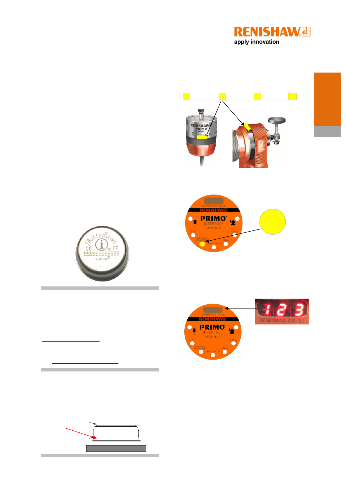
Four low
When any of these low
credit indicators
1.
Equipment LEDs
2.
Interface low battery/credit LED
credit indicators are shown
it is recommended that a
new Primo Credit Token is
loaded into the system.
The basics –
NOTE:
How to purchase credit:
A new 6 month credit token, or an Upgrade credit
token can be purchased from the Primo website
www.primoprobing.com.
You can also contact your local Renishaw supplier.
See www.renishaw.com/contact.
Installation:
Please ensure that the Primo Credit Token is
installed in the Radio Part Setter in the orientation
shown with the lip of the Token inboard. Failing to
do this will result in the Credit not being
transferred
.
3.
Interface digital display (123 days remaining
shown). When the remaining credit display reads 0
days then the Primo System will stop working and
new credit will need to be loaded into the system.
4.
Low battery/credit output from the Interface,
which can be connected to the machine control.
When credit is running low, an alarm will be sent
to the control.
probes
2.4
Primo Radio Part Setter
operation
The Primo Radio Part Setter operates as a highly
accurate and repeatable mechanical switch that
triggers as the stylus deflects against a surface.
The basics –
• The Radio Part Setter can measure in the
• The Primo Radio Part Setter can be used
• A trigger signal is sent directly to the CNC
X, Y and Z axis.
for work co-ordinate setting and for work
piece measurement.
controller so that offsets can be updated
– no manual intervention is required.
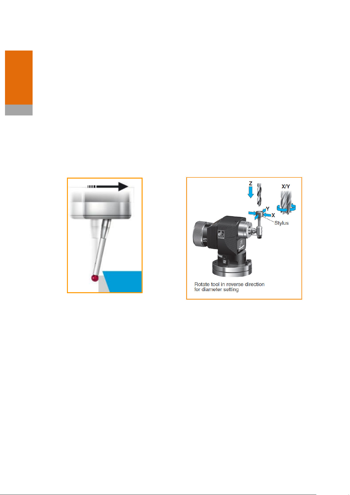
Primo Radio 3D Tool Setter
operation
The Radio 3D Tool Setter enables accurate
machining by measuring the length and diameter
of tools using the same highly accurate and
repeatable switch mechanism has the Primo Radio
Part Setter.
• The tool is set in the Z axis for tool length
measurement and broken tool detection.
• Rotating tools are set in the X and Y axes
for tool radius measurement.

probes
2.5
Primo installation guide
Software routines
Primo Software caters for 3-axis applications and
covers basic probing routines.
• Calibration
• Tool setting
• Broken tool detection
• Work piece set-up
• Work piece measurement
For further information refer to the Primo
Software Programming Guide H – 54XXXX
NOTES:
Software routines for tool setting are available
from Renishaw and are described in data sheet H2000-2289, which can be found at
www.renishaw.com.
Software upgrades - Purchase an upgrade to the
Inspection+ and Five Face Tool Setting package, as
well as the Productivity+ package. See
www.renishaw.com
The basics –

Digital ‘remaining credit’
Primo Interface basics
Introduction
Interface visual diagnostics
The Primo Interface enables communication
between the Machine Tool, Radio Part Setter and
the Radio 3D Tool Setter using radio frequencies.
Power supply
The Interface requires a 12 Vdc to 30 Vdc supply
capable of supplying 150 mA minimum (TBC).
display and Error code
display
3.1
Input voltage ripple
The input voltage ripple must not cause the
voltage to fall below 12 V or go above 30 V.
ReniKey
Renikey is a Renishaw machine programme which
is used while partnering the equipment with the
Interface. Refer to the ReniKey programming
manual for instructions on how to use ReniKey or
refer to www.renishaw.com.
Note:
If the Primo System is using a Primo Upgrade
Credit Token and the Primo Interface is returned
to Renishaw then the Primo Upgrade Credit
Token must be returned with the interface for
identification purposes.

Level
Pulsed
Primo installation guide
Interface
3.2
Interface inputs
Machine start inputs:
‘Machine start’ is configurable as a level or pulsed
signal.
12 to 30 Vdc
The basics -
See section 5.14 for the full wiring diagram.
When input is active probe is switched
on.
12 to 30 Vdc
Part Setter toggles from being
switched on/off. Minimum pulse width
is 10 ms.
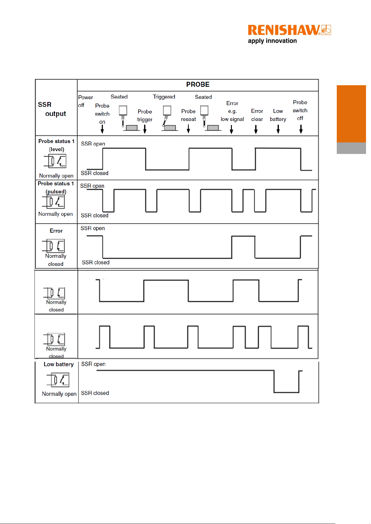
Interface outputs
There are four SSR outputs:
• Probe status 1
• Probe status 2
• Error
• Low battery/credit
All outputs can be inverted by using switches SW1
and SW2 (see section 3.5 for more info).
Note:
The term ‘Probe Status’ refers to the
measurement hardware in the system
interacting with the interface and can
therefore refer to the Primo Radio Part
Setter and the Primo Radio 3D Tool
Setter.
SSR outputs specifications:
• Maximum ‘on’ resistance = 25 ohm
• Maximum load voltage = 30 V
• Maximum load current = 100 mA
Interface
3.3
Interface
/credit
Probe status 2
Probe
status 2
Interface output waveform
Primo
The basics -
(level)
(pulsed)
Signal delays:
1. Transmission delay Probe trigger to output change of state = 10 ms ± 10 µs without enhanced
trigger filter
2. Start delay Time from initiation to start of signal to valid signal transmission = 1 s max
SSR open
SSR closed
SSR open
SSR closed
Interface
3.4
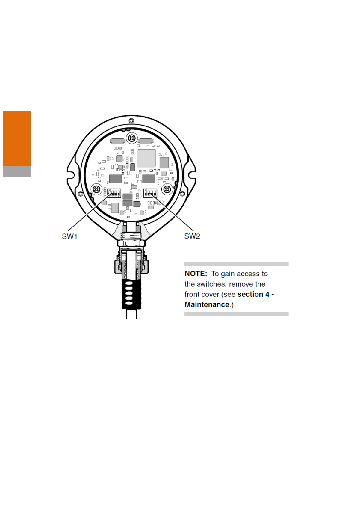
Primo installation guide
Switches SW1 and SW2
PCB diagram like below for Primo
The basics -
N/O
N/C
M-code
START
ENHANCED
HIBERNATION MODE
LOW
Interface
3.5
Disabled
Enabled
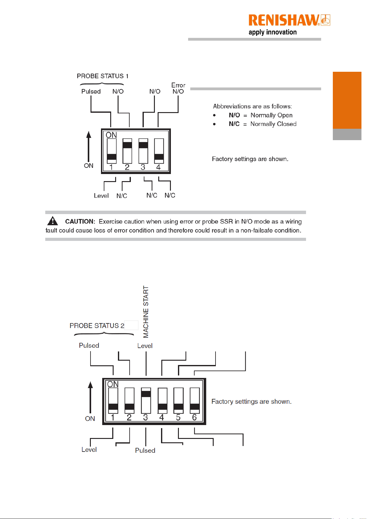
Switch SW1 output configuration
BATTERY
/CREDIT
Note:
If an error code E08 appears on the Primo Interface
Credit remaining/error code display when a switch
setting has been changed the Primo Radio Part Setter
or Primo Radio 3D Tool Setter must be re-acquired.
The basics -
Switch SW2 output configuration
TRIGGER FILTER
Spin
On
Enabled
Off
Disabled
61.25 (2.41
)
Battery cover
Primo credit
Ø
51 (2.00)
21 (0.83)
29.4
(1.16)
Ø
48.5 (1.91)
Primo
Primo
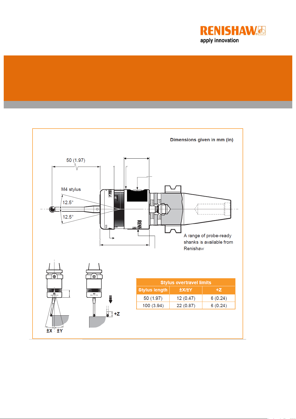
Dimensions and specifications
Part Setter dimensions
4.1
token cover
Primo installation guide
& Specs
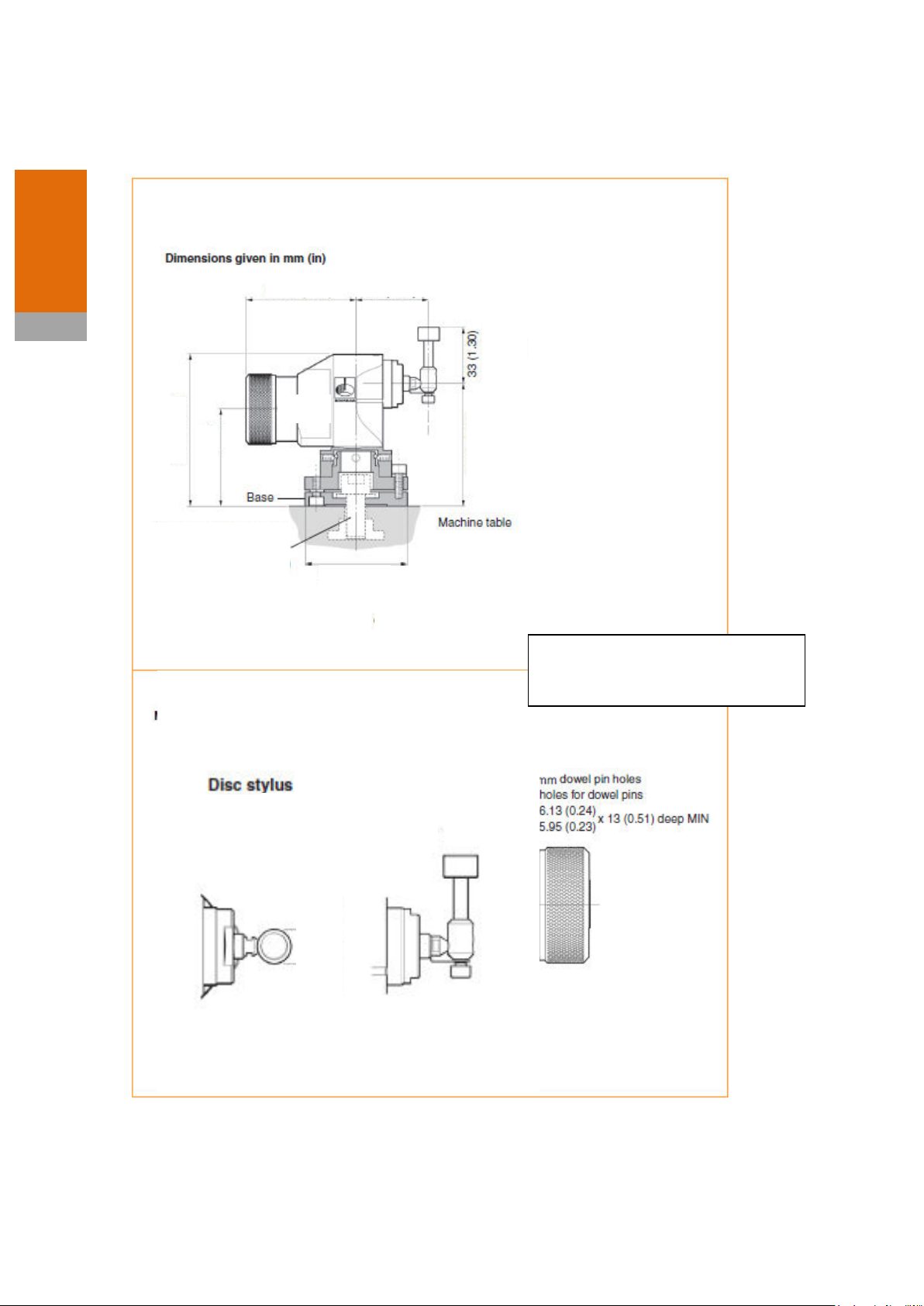
4.2
Ø?
44.551
(1.75)
68.75
(2.70)
93 (3.66)
55 (2.17)
?
?
?
25mm
(Ø
0.98 in x 0.16)
X 4mm
4 (0.16)
Ø
25 (
Ø
0.09)
Primo
3D Tool Setter dimensions
Dimensions
?
Ensure this shows the new, larger disk
stylus
 Loading...