

Page 1
Installation guide
H-1000-5004-04-B
PI 4‑2 probe interface
EXTENDED WARRANTY
Now available for this product.
Contact your vendor.
www.renishaw.com/ew
Page 2

© 2002 - 2008 Renishaw plc. All rights reserved.
This document may not be copied or reproduced in whole or in part, or
transferred to any other media or language, by any means, without the
prior written permission of Renishaw.
The publication of material within this document does not imply
freedom from the patent rights of Renishaw plc.
Disclaimer
RENISHAW HAS MADE CONSIDERABLE EFFORTS TO ENSURE
THE CONTENT OF THIS DOCUMENT IS CORRECT AT THE
DATE OF PUBLICATION BUT MAKES NO WARRANTIES OR
REPRESENTATIONS REGARDING THE CONTENT. RENISHAW
EXCLUDES LIABILITY, HOWSOEVER ARISING, FOR ANY
INACCURACIES IN THIS DOCUMENT.
Trademarks
RENISHAW® and the probe emblem used in the RENISHAW logo are
registered trademarks of Renishaw plc in the UK and other countries.
apply innovation is a trademark of Renishaw plc.
All other brand names and product names used in this document are
trade names, service marks, trademarks, or registered trademarks of
their respective owners.
Renishaw part no: H-1000-5004-04-B
Issued: 06 2008
Page 3

1
PI 4‑2 interface
Installation guide
Page 4

2
FCC
Information to users (FCC section 15.105)
This equipment has been tested and found to comply with the limits for a Class A digital
device, pursuant to Part 15 of the FCC rules. These limits are designed to provide
reasonable protection against harmful interference when the equipment is operated
in a commercial environment. This equipment generates, uses and can radiate radio
frequency energy and, if not installed and used in accordance with the instruction
manual, may cause harmful interference to radio communications. Operation of this
equipment in a residential area is likely to cause harmful interference, in which case
you will be required to correct the interference at your own expense.
Information to the user (FCC section 15.21)
The user is cautioned that any changes or modifications not expressly approved by
Renishaw plc or authorised representative could void the user’s authority to operate the
equipment.
Special accessories (FCC section 15.27)
The user is also cautioned that any peripheral device installed with this equipment
such as a computer, must be connected with a high-quality shielded cable to insure
compliance with FCC limits.
TÜV
This equipment has been independently certified by TÜV Product Services in
accordance with OSHA (US) and SCC (Canada) requirements to the standards
UL61010-1 Second Edition and CAN/CSA-C22-2 No. 61010-1 Second Edition.
Page 5

3
Safety
Electrical requirement
If this product is not used in its intended manner, any protection provided may be
impaired.
The PI 4-2 is powered from the a.c. mains supply via an IEC 320 connector. The
electrical ratings of the unit are as follows:
100-240 V ac +10%, -15% 47 - 66 Hz 10 W
This equipment must be connected to a protective earth conductor via a three core
mains (line) cable. The mains plug shall be inserted only into a socket outlet provided
with a protective earth contact. The protective earth contact shall not be negated by the
use of an extension cable without protective conductor.
WARNING: Any interruption of the protective conductor may make the
equipment dangerous. Make sure that the grounding requirements are strictly
observed.
Environmental requirements
The following environmental conditions comply with (or exceed) BS EN 61010-1:1993:
Indoor use only
IP30 (no protection against water)
Altitude
Up to 2000 m
Operating temperature
0 °C to +50 °C
Storage temperature
-10 °C to +70 °C
Relative humidity
80% maximum for temperatures up to +31 °C
Linear decreases to 50% at +40 °C
Transient voltages
Installation category II
Pollution degree
2
The PI 4-2 is isolated from AC power by disconnection of the IEC mains connector on
the rear panel. If any additional means of isolation is required, it must be specified and
fitted by the machine manufacturer or the installer of the product. The isolator must
be sited within easy reach of the CMM operator and comply with IEC61010 and any
applicable national wiring regulations for the country of installation.
!
Safety
Page 6

4
Care of equipment
Renishaw probes and associated systems are precision tools used for obtaining precise
measurements and must therefore be treated with care.
Changes to Renishaw products
Renishaw plc reserves the right to improve, change or modify its hardware or software
without incurring any obligations to make changes to Renishaw equipment previously
sold.
Warranty
Renishaw plc warrants its equipment provided that it is installed exactly as defined in
associated Renishaw documentation.
Consent must be obtained from Renishaw if non-Renishaw equipment (e.g. interfaces
and/or cabling) is used or substituted. Failure to comply with this will invalidate the
Renishaw warranty.
Claims under warranty must be made from authorised services centres only, which may
be advised by the supplier or distributor.
Patents
Features of Renishaw’s PI 4-2 and associated products are the subjects of the following
patents and patent applications:
EP 242747 B JP 2,539,824 US 4769919 WO 97/35164
EP 279828 B JP 2,647,881 US 4817362
EP 0392660 JP 3,018,015 US 4916339
EP 548328 B JP 3,294,269 US 5,088,337
EP 0501710 JP 3,279,317 US 5,404,649
JP 2,510,804 US 5,339,535
US 5,323,540
US 5,505,005
US 5,918,378
US 6012230
Care of equipment
Page 7

5
Contents
Contents
1 Introduction and general description ..........................................................................7
2 Specification ..............................................................................................................9
2.1 Physical specification .....................................................................................9
2.2 Environmental conditions ...............................................................................9
2.3 Electrical specification ..................................................................................10
3 Unit configuration ..................................................................................................... 11
3.1 Front panel....................................................................................................11
3.2 Rear panel .................................................................................................... 12
4 System configuration ...............................................................................................16
4.1 System interconnection diagrams ................................................................16
4.2 Cables ..........................................................................................................19
4.2.1 PL22T ..........................................................................................19
4.2.2 PL25T ..........................................................................................19
4.2.3 PL26T ..........................................................................................20
4.2.4 HC-2 hand control .......................................................................20
4.2.5 PICS ............................................................................................21
4.2.6 STOP (pin 1) ................................................................................22
4.2.7 PPOFF (pin 2) .............................................................................22
4.2.8 0 V (pin 3) ....................................................................................22
4.2.9 +5 V (output pin 4) .......................................................................23
4.2.10 SYNC (output pin 5) ....................................................................23
4.2.11 HALT (output pin 6) ......................................................................23
4.2.12 PDAMP (pin 7) .............................................................................23
4.2.13 LEDOFF (pin 8) ...........................................................................24
4.2.14 LED anode (input pin 4) ...............................................................24
4.2.15 PICS pull-up (input pin 6) ............................................................24
4.2.16 Probe input (input pins 5 and 9) ..................................................24
4.2.17 Output timings .............................................................................24
Page 8

6
5 Rack mounting ......................................................................................................... 26
5.1 Mounting alone in a 19” rack ........................................................................26
5.2 Mounting next to a PHC10-2 ........................................................................27
6 Maintenance ............................................................................................................28
7 Fault finding .............................................................................................................29
7.1 POWER ON LED will not light ......................................................................29
7.2 PROBE SEATED LED will not light ..............................................................29
7.3 PROBE SEATED LED remains on ...............................................................30
7.4 PROBE SEATED LED correctly lit but output signals fail to reach CMM
controller .......................................................................................................31
Contents
Page 9

7
Introduction and general description
1 Introduction and general description
The function of a probe interface is to manage the probe to ensure that it produces
repeatable and reliable results over a long service life. This is achieved by careful
control of the probe current, trigger threshold and signal conditioning. A probe interface
also controls the head PROBE STATUS LED and provides clean output signals.
The PI 4-2 is a basic probe interface for use with Renishaw’s conventional touch-trigger
probes (TP1, TP20, TP6, MH20i etc.). It is suitable for use on both manual and direct
computer control (DCC) co-ordinate measuring machines (CMMs).
The PI 4-2 has been introduced as a replacement for the PI 4, PI 9 and PI 12 interfaces
and conforms to the relevant CE directives in force at the time of issue. It is housed
in the modern Renishaw enclosure compatible with the latest PHC10-2 and other
controller/interfaces.
The PI 4-2 interface has both solid state relay (SSR) and Renishaw product interconnection system (PICS) output options. It will also support the remote inhibit hand
control unit (HC-2).
Page 10
8
Introduction and general description
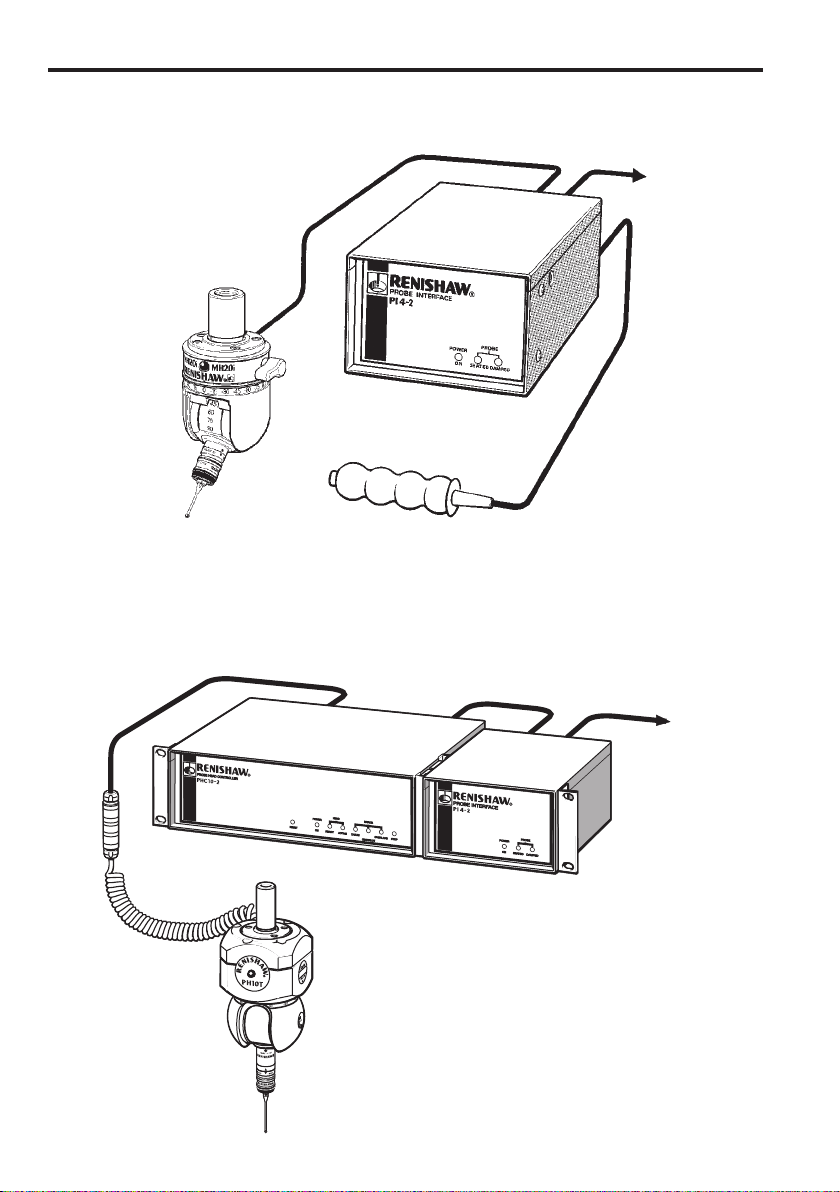
Figure 1
Figure 2
MH20i
PI 4-2
HC-2
to CMM
to CMM
PI 4-2
PHC10-2
PH10T
TP20
Page 11

9
Specification
2 Specification
2.1 Physical specification
Size
1/3 19 ” rack wide × 2U high
(140 mm × 88 mm × 183 mm high)
Mounting
19 ” rack mounting or free standing
Weight
1.6 kg (3.5 lb)
Probe compatibility
Standard probes: TP1, TP20, TP6, MH20i, etc.
Power connector
IEC 320
Probe input connector
9-way D socket (Renishaw PICS standard)
Probe output connector
9-way D plug (Renishaw PICS standard) or 5-pin
DIN SSR socket
System configuration
4 DIL switches
Probe signal cable
50 m, maximum at 24 AWG cores
2.2 Environmental conditions
The following environmental conditions comply with (or exceed) BS EN61010-1:1993
Indoor use only
IP30 (no protection against water)
Altitude
Up to 2000 m
Operating temperature
0 °C to +50 °C
Storage temperature
-10 °C to +70 °C
Relative humidity
80% maximum for temperatures up to +31 °C
Linear decreases to 50% at +40 °C
Transient voltages
Installation category II
Pollution degree
2
Page 12

10
Specification
2.3 Electrical specification
Mains power is supplied on a standard IEC 320 connector.
Power supply
Universal, automatic selection; 100-240 V ac
+10%, -15%, 47-66 Hz
Power consumption
10 W maximum (0.1 A maximum)
Inrush current
40 A, typical at 200 V
SSR contact ratings
±50 V pk
±40 mA pk
NOTE: The PI 4-2 must be earthed.
Page 13

11
Unit configuration
3 Unit configuration
3.1 Front panel
Figure 3
The name, colour and function of the LEDs are given in table 1.
Table 1 ‑ Interface LEDs
Name Colour Function
Power ON Green Mains power ON when lit.
Probe SEATED Green Probe seated when lit.
Probe triggered or not fitted when off.
Probe DAMPED Yellow Lit when PROBE DAMPing has been activated
by the CMM controller or other Renishaw
equipment (PROBE DAMPing reduces the
sensitivity of the probe to unwanted triggers
caused by CMM acceleration or vibration
during position moves).
Page 14

12
Unit configuration
3.2 Rear panel
Figure 4
1 PICS output connector (plug)
The plug configuration is shown below and the pin numbers and designations are given
in table 2.
Table 2 ‑ PICS output connector
Pin number Designation
1
2
3
4
5
6
7
8
9
Body
STOP
Probe power OFF (PPOFF)
0 V
Reserved for Renishaw use
SYNC output (probe trigger)
HALT output
PROBE DAMPing (PDAMP)
LED OFF
Screen
See page 27, ‘Product inter-connection system (PICS)’ for explanation of PICS signals.
1 2 3 4 5
6 7 8 9
1
3
2
4
5
6
7
Page 15

13
Unit configuration
2 PICS input connector (socket)
The socket configuration is shown below and the pin numbers and designations are
given in table 3.
Table 3 ‑ PICS input connector
Pin number Designation
1
2
3
4
5
6
7
8
9
Body
STOP
Probe power OFF (PPOFF)
0 V
Reserved for Renishaw use
Probe signal
+5 V
PROBE DAMPing (PDAMP)
LED OFF
Probe return
Screen
See page 27, ‘Product inter-connection system (PICS)’ for explanation of PICS signals.
5 4 3 2 1
9 8 7 6
Page 16

14
Unit configuration
3 Configuration switches
Switch numbers, positions and designations are given in table 4 (on page 22).
Table 4 ‑ Configuration switches
Switch number Position Designation
1 Up (ON) Output polarity normal:
SYNC high for probe seated, low for probe
triggered
SSR open for probe seated, closed for probe
triggered
Down (OFF) Output polarity reversed
2 Up (ON) Buzzer ON
Down (OFF) Buzzer OFF
3 and 4 * Up (ON) Input polarity normal:
PICS input: Pin 5 = probe input
Pin 9 = 0 V return
Down (OFF) Input polarity reversed:
PICS input: Pin 5 = 0 V return
Pin 9 = probe input
* Switches 3 and 4 must be used together (i.e. BOTH up or BOTH down).
** Although, conventional touch-trigger probes are not polarity sensitive, certain
grounding systems or special probes may require the operation of this switch.
Page 17

15
Unit configuration
4 SSR output (5 pin DIN socket)
The socket configuration is shown below and the pin numbers and designations are
given in table 5.
Table 5 ‑ SSR output
Pin number Designation
1
2
3
4
5
Probe status (a)
Screen
Probe status (b)
Probe status (a)
Probe status (b)
NOTE: The probe status SSR output is connected to pins 1 and 3 and to pins 4 and 5.
5 Mains power connector
This is a standard input plug conforming to IEC 320.
6 Version number label
This label indicates the modification level of the interface. The information may be
relevant when compatibility with other systems is being considered and should always
be quoted when contacting Renishaw for help or service.
7 Serial number
This unique number allocated to your PI 4-2 should be quoted when contacting
Renishaw for help or service.
1
3
4
5
2
Page 18

16
System configuration
4 System configuration
4.1 System interconnection diagrams
Cable A PL22T
Cable B PICS output to CMM (or HC-2)
Cable C SRR output to CMM
Cable D PL1T, 2T, 3T, 4T
NOTE: The cable shown is an alternative output cable.
Figure 5 ‑ PI 4-2 with manual heads
Probe head PH1,
PH6, MH20, MH20i,
MIH, MIH-S
TP20, TP6
Cable D
Cable C
Cable B
Cable A
PI 4-2
Page 19

17
Cable A RS232 or IEEE488 to CMM
Cable B PL25T
Cable C PICS output to CMM
Cable D SSR output to CMM
Cable E PLM 6T, 7T, 8T, 9T
Cable F PL5T, 6T, 12T, 13T
NOTE: The cable shown is an alternative output cable.
Figure 6 ‑ PI 4-2 with PH10T and PHC10-2 controller
System configuration
TP20, TP6
Cable E
Cable D
Cable C
Cable B
PI 4-2
Cable F
Cable A
PHC10-2
AM1
PH10T
Page 20

18
System configuration
TP20, TP6
Cable E
Cable D
Cable C
Cable B
PI 4-2
Cable F
Cable A
PHC10-2
AM1
PH10M
Cable A RS232 or IEEE488 to CMM
Cable B PL25T
Cable C PICS output to CMM
Cable D SSR output to CMM
Cable E PLM 6T, 7T, 8T, 9T
Cable F PL5T, 6T, 12T, 13T
NOTE: The cable shown is an alternative output cable.
Figure 7 ‑ PI 4-2 with PH10-M and PHC10-2 controller
Page 21

19
System configuration
4.2 Cables
Three conventional cables can be used with the PI 4-2: -
• PL22T
• PL25T
• PL26T
Their functions and connections are given below.
4.2.1 PL22T
The PL22T adapts a 5 pin DIN input connector into a 9-pin D-type PICS input.
The 5-pin DIN end is a socket which allows a PI 4-2 input cable to be adapted to a
PICS input (see figure 8).
5-pin DIN socket
5
1
4
3
2
5
3
9
8
6
1
4
Screen
Probe return (low)
Probe signal (high)
0 V
LED anode
Pull-up
STOP
9-pin DIN plug
Figure 8
4.2.2 PL25T
The PL25T is a standard PICS interconnection cable 9-pin D plug to 9-pin D socket. All
connections are pin-to-pin (i.e. 1 to 1, 2 to 2 etc.).
Machine cable PI 4‑2
Page 22

20
System configuration
4.2.3 PL26T
The PL26T cable connects between the 7-pin DIN probe output of a PHC10-2 and the
9-pin D type PICS input of the PI 4-2 (see figure 9).
7-pin DIN plug
5
6
4
7
2
5
2
9
3
8
6
4
Screen
Probe return (low)
Probe signal (high)
Probe inhibit (from PHC9)
0 V
Pull-up
STOP
9-pin DIN plug
PHC9 PI 4‑2
1
3
1
LED anode
Figure 9
4.2.4 HC‑2 hand control
The HC-2 hand control (figure 10) is a simple remote inhibit switch which allows the
machine operator to inhibit the interface while the stylus is changed or the probe head
indexed. It has an LED indicator in the switch button which is lit when the interface is
inhibited.
Figure 10
Page 23

21
System configuration
The HC-2 is intended for use only on manual CMMs and is plugged into the PICS
output connector (see page 18, “Rear panel”)
The socket configuration is shown below and the pin numbers and designations are
given in table 6.
Table 6 ‑ HC‑2 hand control
Pin number Designation
1
2
3
4
5
6
7
8
9
Body
SWITCH (high)
0 V
LED drive
Screen
-
-
-
-
4.2.5 PICS
The product inter-connection system (PICS) has been developed by Renishaw to
simplify the number and variation of cables needed for installations comprising several
controllers/interfaces.
PICS allows a standard method of connection for all real time signals used by current
Renishaw products.
The descriptions given in the following sections are specific to PI 4-2 connections.
For a full explanation of the PICS system see the Renishaw publication PICS
installation guide (part number H-1000-5000).
Table 7 (on page 22) gives pin numbers and input and output functions.
5 4 3 2 1
9 8 7 6
Page 24

22
System configuration
Table 7 ‑ PICS
Pin number PICS output PICS input
1
2
3
4
5
6
7
8
9
STOP
PPOFF (probe power OFF)
0 V
Reserved for renishaw use
SYNC
HALT
PDAMP (probe DAMPing)
LEDOFF
-
STOP
PPOFF (probe power OFF)
0 V
LED anode
Probe signal (high)
PICS pull-up
PDAMP (probe DAMPing)
LEDOFF
Probe return (low)
4.2.6 STOP (pin 1)
This signal is active when low and is responded to, and can be asserted by, the PI 4-2
interface.
It is present on both input and output connectors.
STOP will be asserted only if the internal power rail of the PI 4-2 fails.
If another unit on the PICS bus asserts the stop signal, the PI 4-2 reacts by asserting
both the SYNC and HALT lines irrespective of the status of any of the other PICS lines.
This is carries out to ensure that CMM motion is stopped.
4.2.7 PPOFF (pin 2)
Probe power OFF is an active low inhibit signal produced by another unit on the PICS
bus (the PI 4-2 cannot assert PPOFF).
It is present on both input and output connectors.
The PI 4-2 reacts to PPOFF by inhibiting the SYNC signal (i.e. the output if held high*
irrespective of the probe status). STOP overrides the PPOFF signal.
4.2.8 0 V (pin 3)
This is the common reference and return path for all signals except the un-interfaced
probe inputs on the PICS inputs connector. It is present on both input and output
connectors.
Page 25

23
System configuration
4.2.9 +5 V (output pin 4)
This output is reserved for Renishaw use and consists of a limited +5 V supply to power
certain signal conditioning units.
4.2.10 SYNC (output pin 5)
This is an active low* signal produced by the PI 4-2. It is the output of the probe status,
a normally high* signal which goes low when the probe is triggered.
STOP and PPOFF override the output. STOP forces the signal low. PPOFF forces the
signal high*.
It is present only on the PICS output connector.
4.2.11 HALT (output pin 6)
This is an active low signal produced by the PI 4-2.
It is present only on the PICS Output connector.
The PI 4-2 asserts HALT when the raw probe signal (before debounce) indicates that
the probe has been continuously triggered for at least 5 ms (see figure 11 on page 31).
The function of this output is to indicate the difference between a short vibration trigger
and a genuine trigger event. The scales should be latched when SYNC is received, the
reading accepted and the machine stopped when HALT is received.
* These signals will be inverted if the output polarity switch (SW1) is in the DOWN
position.
4.2.12 PDAMP (pin 7)
PROBE DAMPing is an active low signal produced by another unit on the PICS bus (the
PI 4-2 cannot assert PDAMP).
It is present on both input and output connectors.
PDAMP influences the SYNC output by inhibiting it until the probe has been
continuously triggered for at least 5 ms. Renishaw recommends that PDAMP is
asserted by the CMM controller to reduce the probe’s sensitivity to vibration during
rapid position moves.
Page 26

24
System configuration
4.2.13 LEDOFF (pin 8)
This signal is active when low and can be asserted by the PI 4-2 or another unit in the
PICS bus.
The PI 4-2 asserts LED OFF and the SYNC line at the same time in response to a
trigger event or a STOP signal. The purpose of the LED OFF signal is to control the
LED on the probe signal.
4.2.14 LED anode (input pin 4)
This is a 12 mA LED drive current produced by the PI 4-2 to control the probe head
LED.
It is present on the PICS input only.
This output is connected to the LEDOFF signal at the probe head or its controller to
control the LED.
4.2.15 PICS pull‑up (input pin 6)
This is an 150 W pull-up resistor to +5 V and is used to provide a STOP pull-up for
systems which do not have a probe head controller in the PICS bus.
4.2.16 Probe input (input pins 5 and 9)
These are the probe input connections to the PI 4-2.
4.2.17 Output timings
Standard probe timing
Probe output timings for normal touch-trigger operation are shown in figure 11.
Probe DAMPing
When the probe DAMPing line is pulled low, SYNC will be sent only if the probe is
triggered for longer than 5 ms (see figure 12).
Page 27

25
System configuration
Probe
triggered
Probe
seated
SYNC
SYNC
HALT
Debounce
20 ms
5 ms
NOTE: The HALT signal is a minimum of 20 ms long. If the signal is more than 5 ms
but less than 25 ms these edges will not coincide.
Figure 11
Probe
triggered
Probe
seated
5 ms 5 ms 5 ms
5 ms
delay
Figure 12
Page 28

26
Rack mounting
5 Rack mounting
WARNING: Ensure the PI 4-2 is disconnected from the mains supply during
installation.
WARNING: Take care not to exceed the operation ambient of 50 °C around the
unit. Do not install near sources of heat. Forced cooling may be required in final
installation.
NOTE: Use the mounting screws supplied with this equipment. DO NOT replace with
longer screws as damage could occur.
5.1 Mounting alone in a 19” rack
The PI 4-2 can be used in a 19” rack system or as a stand alone unit.
Figure 13 below shows a PI 4-2 mounted to a 19” rack system.
Remove the blanking plugs from side panels of the PI 4-2 and fit the 1/3 blanking
panels (1) using the screws provided.
Fit the completed assembly to the rack.
Figure 13
!
!
Page 29

27
Rack mounting
The rack mounting bracket kit part no. A-1018-0124.
The enclosure link bracket kit part no. A-1018-0126.
Figure 14
5.2 Mounting next to a PHC10‑2
The 1/3 blanking panel kit part number is A-1018-0123.
Figure 14 (on page 26) shows the PI 4-2 mounted next to a PHC10-2. Fit a rack mount
bracket (1) and an enclosure link bracket (2) using the screws provided.
Remove the blanking plugs from the PHC10-2 (if fitted) and, using the screws provided,
fit an enclosure link bracket and a rack mount bracket.
The enclosure mount brackets must be fitted in the orientations shown. Fit the link
brackets to the units before fitting the link brackets together. Using the screws provided,
fit together to PI 4-2 and the PHC10-2. The complete linked assembly is ready for
fitting to the rack.
Page 30

28
Maintenance
6 Maintenance
There are no user serviceable parts within the PI 4-2.
The PI 4-2 may be wiped clean using a clean dry cloth.
Page 31

29
Fault finding
7 Fault finding
There are several test which can be safely carried out while power to the PI 4-2 is on.
DO not remove the cover in any circumstances.
7.1 POWER ON LED will not light
This will normally indicate that no power is applied to the unit (it is driven from an
internal d.c. supply).
Check that:
• The mains power cable is firmly connected.
• There is mains power to the mains cable.
If these checks do not correct the problem the PI 4-2 should be returned to Renishaw
for repair.
7.2 PROBE SEATED LED will not light
This will normally indicate that the probe is triggered or not connected.
Check that:
• The rear panel switches 3 and 4 are both up or both down (switches 3 and 4 must
always be in the same position, see section 3.3)
• Disconnect the PICS input connector and put a link (short circuit) between pins 5
and 9 of the PI 4-2 input plug. Check that PROBE SEATED LED is still off.
If these checks do not isolate the problem the PI 4-2 should be returned to Renishaw
for repair.
If the link (short circuit), described above, switches the PROBE SEATED LED on, the
fault is in the input (CMM wiring, probe head or probe). See the appropriate product
documentation.
Page 32

30
Fault finding
7.3 PROBE SEATED LED remains on
This will normally indicate that the probe is seated.
Check that:
• The LED goes off when the PICS Input connector is removed.
• The LED goes off when the HC-2 is disconnected (if fitted).
If removing the PICS Input connector switches the PROBE SEATED LED off, the
fault is in the input (CMM wiring, probe head or probe). See the appropriate product
documentation.
If removing the HC-2 input (when not set to inhibit), switches the PROBE SEATED LED
off, the problem is in the HC-2 (which should be returned to Renishaw for repair).
If these checks do not isolate the problem the PI 4-2 should be returned to Renishaw
for repair.
Page 33

31
Fault finding
7.4 PROBE SEATED LED correctly lit but output signals
fail to reach CMM controller
Perform the following procedures -
1. Remove the PICS output connector.
2. Using a voltmeter connected between pin 3 (0 V) and pin 5 (SYNC) on the PICS
output socket.
When the stylus is seated the output voltage should be between 4 V and 5 V d.c. When
the stylus is deflected the output voltage should be between 0 V and 1 V d.c. If switch 1
is DOWN the output voltages will be reversed (i.e. 0 V seated, 5 V deflected).
OR, if the SSR output is being used:
1. Remove the SSR output connector.
2. Using a resistance meter connect the pin 1 (probe status, a) and pin 3
(probe status, b).
When the stylus is seated the resistance should be less than 10 Ω. When the stylus
is deflected the resistance should be greater than 1 MΩ. If switch 1 is DOWN the
resistances will be reversed (i.e. more than 1 MΩ seated, less than 10 Ω deflected).
If these checks do not correct the problem the PI 4-2 should be returned to Renishaw
for repair, otherwise the fault is either in the output cable or the CMM controller input
(see the appropriate product documentation).
Page 34

Renishaw plc
New Mills, Wotton-under-Edge,
Gloucestershire, GL12 8JR
United Kingdom
T +44 (0)1453 524524
F +44 (0)1453 524901
E uk@renishaw.com
www.renishaw.com
For worldwide contact details,
please visit our main web site at
www.renishaw.com/contact
*H-1000-5004-04*
 Loading...