

Page 1
PHC10-3 PLUS installation guide
Document part number: H-1000-0077-01-A
PHC10-3 PLUS installation guide
http://www.renishaw.com
Issued 01 2013
Page 1 of 30
Page 2

General Information
©2012Renishawplc.Allrightsreserved.
This document may not be copied or reproduced in whole or in part, or transferred to any other media or language, by any means, without
the prior written permission of Renishaw.
The publication of material within this document does not imply freedom from the patent rights of Renishaw plc.
Disclaimer
RENISHAW HAS MADE CONSIDERABLE EFFORTS TO ENSURE THE CONTENT OF THIS DOCUMENT IS CORRECT AT THE
DATE OF PUBLICATION BUT MAKES NO WARRANTIES OR REPRESENTATIONS REGARDING THE CONTENT. RENISHAW
EXCLUDES LIABILITY, HOWSOEVER ARISING, FOR ANY INACCURACIES IN THIS DOCUMENT.
Trademarks
RENISHAW® and the probe emblem used in the RENISHAW logo are registered trademarks of Renishaw plc in the UK and other
countries.
apply innovation is a trademark of Renishaw plc.
All brand names and product names used in this document are trade names, service marks, trademarks, or registered trademarks of their
respective owners.
Windows XP, Windows 2000, Vista and Windows 7 are registered trade names of the Microsoft Corporation.
All trademarks and trade names are acknowledged.
Care of equipment
Renishaw probes and associated systems are precision tools used for obtaining precise measurements and must therefore be treated
with care.
Changes to Renishaw products
Renishaw reserves the right to improve, change or modify its hardware or software without incurring any obligations to make changes to
Renishaw equipment previously sold.
Warranty
Renishaw plc warrants its equipment for a limited period (as set out in our Standard Terms and Conditions of Sale) provided that it is
installed exactly as defined in associated Renishaw documentation.
Prior consent must be obtained from Renishaw if non-Renishaw equipment (e.g. interfaces and/or cabling) is to be used or substituted.
Failure to comply with this will invalidate the Renishaw warranty.
Claims under warranty must be made from authorised service centres only, which may be advised by the supplier or distributor.
PHC10-3 PLUS installation guide
http://www.renishaw.com
Issued 01 2013
Page 2 of 30
Page 3

EC declaration of conformity
Renishaw plc hereby declares that the PHC10-3 PLUS probe head controller is in compliance with the essential requirements and other
relevant provisions of EU Directive 2004/108/EC .
Contact Renishaw plc at www.renishaw.com for the full EC Declaration of Conformity.
PHC10-3 PLUS installation guide
http://www.renishaw.com
Issued 01 2013
Page 3 of 30
Page 4

FCC (USA only)
Information to user (47CFR section 15.105)
This equipment has been tested and found to comply with the limits for a Class A digital device, pursuant to Part 15 of the FCC rules.
These limits are designed to provide reasonable protection against harmful interference when the equipment is operated in a commercial
environment. This equipment generates, uses, and can radiate radio frequency energy and, if not installed and used in accordance with
the instruction manual, may cause harmful interference to radio communications. Operation of this equipment in a residential area is likely
to cause harmful interference, in which case you will be required to correct the interference at your own expense.
Information to user (47CFR section 15.21)
The user is cautioned that any changes or modifications not expressly approved by Renishaw plc or authorised representative could void
the user's authority to operate the equipment.
Equipment label (47CFR section 15.19)
This device complies with part 15 of the FCC Rules. Operation is subject to the following two conditions:
1. This device may not cause harmful interference.
2. This device must accept any interference received, including interference that may cause undesired operation.
WEEE
The use of this symbol on Renishaw products and/or accompanying documentation indicates that the product should not be mixed with the
general household waste upon disposal. It is the responsibility of the end user to dispose of this product at a designated collection point
for waste electrical and electronic equipment (WEEE) to enable reuse or recycling. Correct disposal of this product will help save valuable
resources and prevent potential negative effects on the environment. For more information, please contact your local waste disposal
service or Renishaw distributor.
PHC10-3 PLUS installation guide
http://www.renishaw.com
Issued 01 2013
Page 4 of 30
Page 5

Safety
If the equipment is used in a manner not specified by the manufacturer, the protection provided by the equipment may be impaired. There
are no user serviceable parts inside the equipment.
The PHC10-3 head controller is to be used with the provided PSU - Emerson DP4024N3M. See manufacturer's datasheet at
www.emerson.com
PSU electrical ratings
Supply voltage 100 V - 240 Vac +10% -10%
Frequency range 50 Hz to 60 Hz
Power consumption 49 W max
Transient voltages Installation category II
PHC10-3 is isolated from ac power by disconnection of the IEC mains connector from the supplied PSU. If any additional means of
isolation is required, it must be specified and fitted by the machine manufacturer or installer of the product. The isolator/disconnection
device must be sited within easy reach of the operator and comply with any applicable national wiring regulations for the country of
installation.
PHC10-3 PLUS installation guide
http://www.renishaw.com
Issued 01 2013
Page 5 of 30
Page 6

Environmental conditions
The following environmental conditions comply with those defined in BS EN61010 - 1:2001
Indoor use IP30 (no protection against water)
Altitude Up to 2000 m
Operating temperature 0°Cto+50°C
Storage temperature 10°Cto+70°C
Relative humidity 80%maximumfortemperaturesupto+31°C
Lineardecreaseto50%at+50°C
Pollution degree 2
PHC10-3 PLUS installation guide
http://www.renishaw.com
Issued 01 2013
Page 6 of 30
Page 7

References and associated documents
User's guide: Touch-trigger probes H-1000-5021
User's guide: SP25M H-1000-5104
User's guide: HCU1 H-1000-5016
User's guide: AM1 H-1000-4010
User's guide: AM2 H-1000-2051
Technical specification: Styli and accessories H-1000-3200
Installation guide: PICS H-1000-5000
Installation and user's guide: PH10 PLUS H-1000-7592
PHC10-3 PLUS installation guide
http://www.renishaw.com
Issued 01 2013
Page 7 of 30
Page 8
Introduction
The guide gives information on physical installation, system connections, communications and interface settings, as well as assistance in
fault-finding during the installation of PHC10-3 PLUS.
WARNING: The components of PH10 PLUS system are not compatible with PH9 or PH20 system components. No attempt should
be made to connect PH10 PLUS system components to a PH9 or PH20 system, as this will result in damage to the product.
The guide should be read in conjunction with the PH10 PLUS series user's guide in order to fully understand the system's features,
capabilities and operation.
The PH10 PLUS series of motorised probe heads can only be used in conjunction with the PHC10-3 PLUS and the UCC2 PH10
daughtercard. PHC10-3 PLUS has replaced the PHC10-2 and provides support for RS232 and USB communications (IEEE is no longer
supported). PHC10-3 PLUS uses an external power supply for the PH10 PLUS series of heads, manages all the head functions and
communicates via a suitable interface with the CMM's computer. PHC10-3 PLUS does not manage the probe functions but does have the
provision for an interface to be fitted.
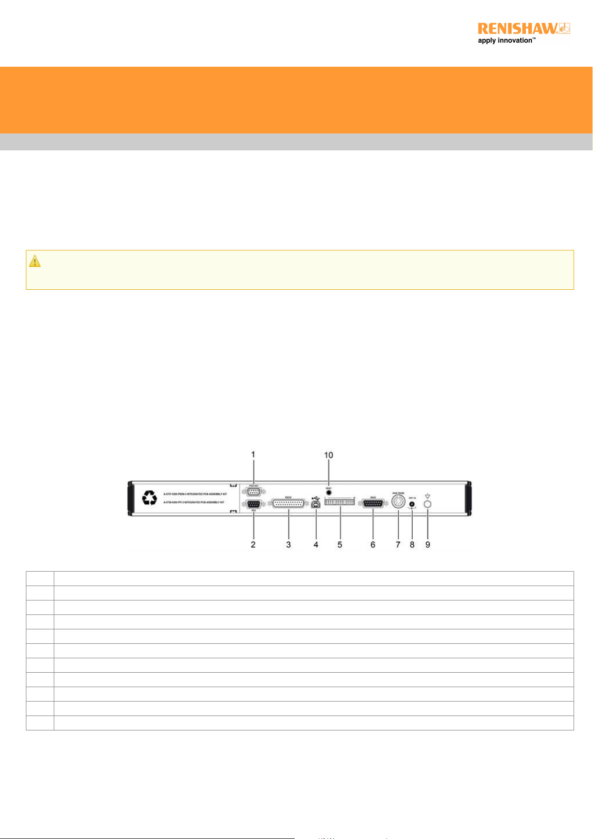
Rear panel layout
Key Description
1 9-way D-type plug for PICS output
2 9-way D-type connector to HCU1
3 25-way D-type plug RS232 communications connector to CMM computer
4 USBtype“B”socket
5 PHC10-3 PLUS configuration switches
6 15-way D-type connector to probe head
7 7-pin DIN raw probe connector to probe interface or multiwire input for internal interfaces
8 DC power jack
9 Equipment bond point
10 Controller reset button
PHC10-3 PLUS installation guide
http://www.renishaw.com
Issued 01 2013
Page 8 of 30
Page 9

PHC10-3 PLUS configuration switches
PHC10-3 PLUS switch settings
PHC10-3 PLUS switch Function Up Down
Communications
1# Baud rate
2# Baud rate
3# Baud rate
4*# Stop bit 2 stop bits 1 stop bit
5*# CTS protocol CTS on CTS off
6*# LF protocol LF on LF off
9 Command set Extended Basic
Interface
7 PICS configuration PROFF - active during head index PROFF - inactive during head index
8 HCU1 PROBE/DAMP/RESET Enabled Disabled
10 Probe reset time 2 (extended) 1 (standard)
11 Interface connection PICS / 7 pin DIN 5 pin DIN
12 Output configuration PICS DIN
13 Machine cable isolation Machine cable Multiwire
* Operational only when basic command set selected (switch 9 down).
# Not required for USB operation default position = down.
NOTE: Press the reset button after making switch changes.
Conversion from PHC10-2 to PHC10-3 PLUS
PHC10-3 PLUS is designed to be a plug in functional replacement for PHC10-2. There are some differences which the user needs to be
aware of, the connectors have been rearranged on the rear panel but are of the same type and are labelled in the same way. A USB
connector has been added for those requiring USB communications. Unused switches have been removed and the remaining switches
are now grouped in one row. See the next table for changes.
PHC10-3 PLUS installation guide
http://www.renishaw.com
Issued 01 2013
Page 9 of 30
Page 10

Changes in configuration switches
The table below is a summary of the differences between PHC10-3 PLUS and PHC10-2 configuration switch settings that allows you to
correctly configure your PHC10-3 PLUS when replacing a PHC10-2.
PHC10-2 switch PHC10-3 PLUS switch
equivalent
Function Up Down
Communications
1 1# Baud rate
2 2# Baud rate
3 3# Baud rate
4 (not used)
5 (not used)
6 4*# Stop bit 2 stop bits 1 stop bit
7 5*# CTS protocol CTS on CTS off
8 6*# LF protocol LF on LF off
9 9# Command set Extended Basic
10 10 Probe reset time 2 (extended) 1 (standard)
Interface
11 7 PPOFF PPOFF - active during
head index
PPOFF - inactive during
head index
12 8 HCU1 probe, DAMP and probe
reset buttons
Enabled Disabled
13 (not used)
14 (not used)
15+16 12 Output configuration PICS DIN
17+18 11 Interface connection PICS or 7 pin DIN
operation
5 pin DIN operation only
13 Probe wire isolation Machine cable Multiwire
* Operational only when basic command set selected (switch 9 down)
# Not required for USB operation default position = down
NOTE: Switches 4, 5, 13 and 14 had no function in RS232 PHC10-2. Press the reset switch after making switch position changes.
PHC10-3 PLUS installation guide
http://www.renishaw.com
Issued 01 2013
Page 10 of 30
Page 11

PICS connection
PICS interface configuration
If PHC10-3 PLUS is to be used in a PICS linked system, the PPOFF configuration is selected using switch 7.
Switch Description Position Information
7 PPOFF UP PPOFF and PDAMP active during head index
7 PPOFF DOWN PDAMP only active during head index
PICS output
Renishaw's PICS (product inter-connection system) allows a standard method of connection for real-time signals used by current
Renishaw products and gives access to probing system control features through the DIN 'raw probe' connection.
The following descriptions are specific to PHC10-3 PLUS PICS connections when an internal interface is not present. Please refer to the
PICS installation guide (Renishaw part number H-1000-5000) for further information when interfaces are fitted.
PHC10-3 PLUS installation guide
http://www.renishaw.com
Issued 01 2013
Page 11 of 30
Page 12

PinSignal Function -
1 STOP
This signal is active when low and is responded to, and can be asserted by the PHC10-3 PLUS .
Read from PHC10-3
PLUS to indicate an
error in the PH10
system. Pull down to 0
V to indicate a STOP
condition external to the
PH10 system.
2 PPOFF PPOFF is an active low inhibit signal which can be set by the CMM computer or the PHC10-3
PLUS. PPOFF is overridden by the use of the STOP signal.
-
3 0 V This the common reference and return path for all signals. 4 LED
anode
This is a constant current input, normally from the interface to illuminate the head LED. -
5 Probe
Signal
This pin and pin 9 transmit the probe output signals from the PHC10-3 PLUS when a multiwire
cable is not in use. As these signals have not been interfaced, it is important that the PICS cable
between the PHC10-3 PLUS and the interface is less than 0.5 m (1.6 ft) otherwise interference
from other PICS signals can occur.
-
6 SPARE - 7 PDAMP PDAMP is an active low signal which can be set by the CMM computer, the PHC10-3 PLUS or by
the optional HCU1. PDAMP can influence an interface by reducing electronically the sensitivity of a
strain gauge based probe. It can inhibit a Renishaw interface, when standard touch trigger probes
are in use, until the probe has been continuously triggered for at least 5 ms. The signal can be
asserted by the CMM computer to reduce the sensitivity of the probe. This will reduce unwanted
triggers during CMM acceleration, or vibration during position moves, whilst maintaining crash
protection.
Pull down to 0 V to
partially inhibit the
probe during rapid
moves.
8 LEDOFFThis signal is not asserted by the PHC10-3 PLUS, but it responds to LED OFF by switching the
head LED off.
-
9 Probe
Return
See Pin 5 -
- Screen - -
PHC10-3 PLUS installation guide
http://www.renishaw.com
Issued 01 2013
Page 12 of 30
Page 13

PHC10-3 PLUS front panel LEDS
PHC10-3 PLUS LED description
Name Colour Function
POWER Green Power on when lit
STOP Red PHC10-3 PLUS asserting PICS STOP when lit
PI 200 asserting PICS STOP when flashing
HEAD READY Green Head ready for use when lit
HEAD ACTIVE Yellow Head indexing when lit
DATUM ERROR Red Head datum error when lit
OBSTRUCT ERROR Red Head obstruct error when lit, non PLUS interface fitted
OVERLOAD ERROR Red Head overload error when lit
TP7 Green TP7 detected when lit
TP200 Green TP200 detected when lit
STD Green TP2 / TP20 / TP6 detected when lit
SEATED Green Probe seated when lit
DAMPED Yellow Probe damped when lit
NOTE: The probe reset button on the front of PHC10-3 PLUS only functions if a probe interface card is installed within the unit.
PHC10-3 PLUS with integrated probe interface
PHC10-3 PLUS is available with an integrated PI 200-3 allowing additional PICS output (Renishaw part number A-5863-0300).
PHC10-3 PLUS installation guide
http://www.renishaw.com
Issued 01 2013
Page 13 of 30
Page 14

System interconnection diagrams
This section describes a number of PH10 PLUS system interconnection and recommended interconnection cables
PH10 PLUS system with standard two wired touch-trigger probes
PHC10-3 PLUS installation guide
http://www.renishaw.com
Issued 01 2013
Page 14 of 30
Page 15

PH10 PLUS system with standard two wire touch-trigger probe and autochange
1 Communication connection to CMM controller RS232 or USB
3 Communication to CMM controller
4 Communication to autochange rack
5 PICS output to CMM
6 Probe output to CMM controller
PHC10-3 PLUS installation guide
http://www.renishaw.com
Issued 01 2013
Page 15 of 30
Page 16

PH10 PLUS system with standard two wire touch-trigger probe, PI 200-3 and autochange
1 Communication connection to CMM controller - RS232 or USB
3 Communication to CMM controller
4 Communication to autochange rack
5 PICS output to CMM controller
6 Raw probe output to CMM contoller
PHC10-3 PLUS installation guide
http://www.renishaw.com
Issued 01 2013
Page 16 of 30
Page 17

RS232 setup
RS232 connector pinouts
The PHC10-3 PLUS communicates with the CMM computer via the RS232 cable as shown in the table below:
Pin Signal
1 Screen
2 Transmitted data (Tx) to CMM computer
3 Received data (Rx) from CMM computer
4 RTS (request to send) to CMM computer +12 V after initialisation routing completed
5 CTS (clear to send) from CMM computer
CMM computer disasserts CTS to halt PHC10-3 PLUS transmissions
Connect pin 5 to pin 20 if CTS is not output from CMM computer
7 Signal ground (common)
20 DTR (data terminal ready) to CMM computer signifies PHC10-3 PLUS power ON condition
Baud rate selection
The baud rate is set using switches 1 to 3 as shown in the table below:
Baud rate Switch 1 Switch 2 Switch 3
300 DOWN DOWN DOWN
600 UP DOWN DOWN
1200 DOWN UP DOWN
2400 UP UP DOWN
4800 DOWN DOWN UP
9600 UP DOWN UP
19200 DOWN UP UP
CAUTION: To implement any changes press the "reset" button on the rear rear panel. Failure to do so will be the changes do
not take effect.
Protocol selection
The PHC10-3 PLUS has two switch-settable command sets (basic command set and extended command set) offering different protocol
options. The command set selection is made using switch 9 on the rear panel.
Switch Position Selection
9 UP Extended command set mode (recs) 9 DOWN Basic command set mode
PHC10-3 PLUS installation guide
http://www.renishaw.com
Issued 01 2013
Page 17 of 30
Page 18

Basic command set mode
In this mode the PHC10-3 PLUS is fully compatible with existing integration methods in terms of communications protocols, software
command set and RS232 protocol options.
Basic command set protocol
Switch Position Selection
4 UP 2 stop bits
4 DOWN 1 stop bit
5 UP CTS (clear to send) ON
5 DOWN CTS (clear to send) OFF
6 UP LF (line feed) ON
6 DOWN LF (line feed) OFF
Data transmission format is as follows:
1 start bit
7 data bits
1 parity bit (ignored on Rx: always 0 on Tx)
1 or 2 stop bits (switch 4)
Protocols: PHC10-3 PLUS RTS is asserted before first transmission from the head and remains asserted. If switch 5 is UP, CTS must be
asserted by the CMM computer to allow the head to transmit. If switch 6 is UP, the PHC10-3 will add an ASCII LF character to every
transmitted message.
Extended command set mode
In this mode the PHC10-3 PLUS uses the Renishaw extended command set. It is completely different from and incompatible with the
basic command set. The RS232 protocol is fixed with no user selectable options other than baud rate. The extended command set offers
the following advantages over the basic command set:
Software control of the hand control unit (HCU1) functions such as jog and sweep
Software control of selected PICS (product interconnection system) functions such as probe damping, Probe Power OFF and LED
OFF
Software control of selected probe functions (TP200 probe reset) Common communications protocol for products using the extended
command set
As probing systems become increasingly sophisticated and offer a wider range of functions and control options, they will be
incorporated into the new command structure, reducing integration times and costs for CMM manufacturers
The introduction of product identifiers and device numbers will enable control of multiple Renishaw interfaces in future implementations
of the extended command set
Please contact Renishaw for further details of the extended command set.
NOTE: The functions of switches 4, 5 and 6 will have no effect on the system when switch 9 is UP
In extended command set mode, the data transmission and protocol formats are fixed in line with modem RS232 conventions. There are
no user selectable options.
PHC10-3 PLUS installation guide
http://www.renishaw.com
Issued 01 2013
Page 18 of 30
Page 19

Data transmission format is as follows:
1 start bit
7 data bits
1 even parity bit
1 stop bit
Protocol:
PHC10-3 PLUS RTS is normally asserted. It is unasserted when the PHC10-3 PLUS is unable to receive further transmissions.
The PHC10-3 PLUS CTS must be asserted (by the CMM computer, or by linking DTR to CTS) to allow the PHC10-3 to transmit.
XON/XOFF:
The extended command set supports the use of XON/XOFF flow control by the CMM computer.
If the PHC10-3 PLUS receives an XOFF character, PHC10-3 PLUS transmissions will cease and be buffered until an XON character
is received by the PHC10-3 PLUS or the output buffer overflows.
It is possible to continue transmissions to the PHC10-3 PLUS while it is in the XOFF state, although this is not recommended as it may
cause overflow of the output buffer, resulting in lost responses.
PHC10-3 PLUS installation guide
http://www.renishaw.com
Issued 01 2013
Page 19 of 30
Page 20

USB communications
USB communication is via the USB type "B" socket on the rear panel. The PHC10-3 PLUS is self powered and therefore takes no power
from the PC bus. The PHC10-3 PLUS will switch automatically from RS232 to communicate via the USB port if a powered up cable is
connected.
NOTE: Only one type of communications cable is to be inserted at any time. If in USB mode and the cable is removed, the PHC10-3
PLUS will assert PICS STOP
Switches 1 to 6 have no function when operating via USB. They may be set to the default down position or left in the RS232 positions.
Switches 7, 8, 9, 11, 12 and 13 will operate as described in the interface switches section.
To operate via the USB port the CMM PC will require the correct USB drivers to be loaded. The signed drivers are available on the CD
provided. To load the drivers power up a PHC10-3 and connect to the CMM PC via a USB cable. The CMM PC operating system should
recognisethenewhardwareandthe‘foundnewhardware'wizardwilloffertosearchforthedriver.
To conform to USB standards a maximum cable length of 5 m may be used. If a longer distance is required a hub may be used to extend
another 5 m. The maximum length of hubs / cables is 30 m. It is suggested that the PHC10-3 should not share its USB port with any high
data rate device which may slow down its response time. Devices such as video cameras and disc drives for example should be avoided
if possible.
PHC10-3 PLUS installation guide
http://www.renishaw.com
Issued 01 2013
Page 20 of 30
Page 21

Interface switch descriptions
HCU1 operation
When the system is used in conjunction with an HCU1 hand control unit, the probe damp and probe reset buttons on the HCU1 are active.
The probe reset button will pulse the PPOFF PICS line when pressed, but only while the system is in manual mode. The probe damp
button will toggle the PDAMP PICS line when pressed, but only while the system is in manual mode. Both the probe reset and probe damp
buttons on the HCU1 can be made inactive by use of a switch on the rear panel of the PHC10-3.
Switch Description Position
8 Operation of HCU1 probe UP Enabled
8 Damping and probe reset DOWN Disabled
Probe reset time
The extended probe reset timer on the PHC10-3 PLUS unit is designed to be used where the touch probe fails to remain seated following
a head index move. E.g, when using long extension bars.
Switch Description Position
10 Time permitted for probe to reseat following a head index UP Level 2 (extended)
10 Time permitted for probe to reseat following a head index DOWN Level 1 (standard)
Interface connection
SwitchDescription Position
11 Probe
connection
UP PICS or 7-pin DIN operation: the PHC10-3 PLUS internal inhibit realy disables the interface during a
head index
11 Probe
connection
Down 5-pin DIN operation only: the PHC10-3 internal inhibit relay disables the probe during a head index
Output configuration
The PHC10-3 PLUS can be connected to a probe interface via the PICS connection or via the Raw Probe connection (7 pin DIN
connector).
Switch Description Position
12 Probe output configuration UP PICS
12 Probe output configuration DOWN DIN
Probe wire isolation
The probe wires need to be isolated from the machine cable wiring when used with multiwire systems. This is controled by switch 13.
PHC10-3 PLUS installation guide
http://www.renishaw.com
Issued 01 2013
Page 21 of 30
Page 22

Switch Description Position
13 For use with machine cable UP Machine cable
13 Multiwire option for use with PL172 DOWN Multiwire
The PHC10-3 PLUS will assert STOP under the following conditions:
Condition Notes
Overload error Head has been overloaded when locked causing it to unlock
Obstruct error Head has been obsructed when moving to requested position or is unable to lock into it
Head disconnect STOP will be asserted for two seconds if head is disconnected
Power failure Stop signal will be permanently asserted if mains power is removed from PHC10-3 PLUS
USB cable disconnected PICS STOP will be asserted if USB cable is used and removed during operation
The reaction to assertion of PICS STOP to the system and effect of the signal removal are detailed below:
System state Reaction Removal of external
STOP
STOP asserted on power up head locked
Normal system start up - head will report its position Head movement
commangs accepted
System in manual mode - manual
movement initiated by HCU1 after
STOP asserted
Single step manual movement only - continuous movement is disabled but
head can be moved slowly as a safeguard movement. Head will lock up as
normal when movement key is released
Continuous movement
enabled
System in manual mode - STOP
asserted during manual move by
HCU1
Continuous head movement is immediately disabled - head will continue to
move in single steps. Head will lock up as normal when movement key is
released
Continuous movement
enabled
System in automatic mode - stop
asserted before update command
received
PHC10-3 PLUS will not unlock or index the head Normal system
operation resumed
System in automatic mode - stop
asserted during a head move
Power immediately removed from axis motors - motors braked Update command will
cause the head to
complete its move
PHC10-3 PLUS installation guide
http://www.renishaw.com
Issued 01 2013
Page 22 of 30
Page 23

Power supply
Powering the PHC10-3 PLUS
The PH10-3 PLUS head controller is to be used with the provided PSU - (Emerson DP4024N3M ac power adptor). www.emerson.com
Thisisa24Vdc49WsupplyandisconectedtothePHC103PLUSviaØ5.5mmdcjackplug.
PHC10-3 PLUS does not does require a protective earth, however an equipotential bonding point is provided on the rear panel for
connection to the rest of the installation.
PHC10-3 PLUS controller is rated to operate at +24 Vdc 1 A max input current
If an internal interface is fitted with the PHC10-3 PLUS it will obtain its power internally from the PHC10-3 PLUS controller.
PHC10-3 PLUS installation guide
http://www.renishaw.com
Issued 01 2013
Page 23 of 30
Page 24

Head connector and cables
NOTE: For maximum immunity from electrical noise, Renishaw recommends that:
1. Mating connectors must be metal bodied.
2. The overall cable screen is continuous and connected to the system ground on the user's equipment through the bodies of the
connectors.
CAUTION: For correct system function, the maximum overall single core resistance between the head and PHC10-3 PLUS should
be 2.5 ohm.
Head connector cables
PHC: Probe head cable
MC: Machine cable
MC MC MC MC PHC PHC PHC
Signal name 15-way male D-type Cable PLM 6 - 9 14-way LEMO 12 core 14-way Max line
B-axis feedback 14 Black (F) 1 (M) Yellow E n/a
Ground sense 1 Brown (F) 2 (M) Red D n/a
DC reference 12 V 6 Violet (F) 3 (M) Brown C n/a
0 V 4 Green/red (F) 4 (M) Grey M 1000 mA
Locking motor 8 V dc nominal 10 Green (F) 5 (M) White H 350 mA
A-axis motor 12 V dc nominal 12 Red (F) 6 (M) Green L 350 mA
Head present 2 Turquoise (F) 7 (M) Not connected ------- ------A-axis motor 12 V dc nominal 11 White (F) 8 (M) Dark blue F 350 mA
B-axis motor/probe contact 7 Pink (F) 9 (M) Violet A 350 mA
B-axis motor/probe contact 15 Orange (F) 10 (M) Black B 350 mA
Screen Body Screen (F) 11 (M) Screen N, O ------A-axis feedback 3 Yellow (F) 12 (M) Orange G n/a
LED and datum 8 Blue (F) 13 (M) Turquoise J 15 mA
Motor probe switch 5 Grey (F) 14 (M) Pink K 40 mA
NOTE: The male pins numbered 4 and 7 of the 14 way LEMO connector are linked together.
Motorised head cables
The table below shows the standard range of motorised head cables available from Renishaw:
PHC: Probe head cable
MC: Machine cable
PHC10-3 PLUS installation guide
http://www.renishaw.com
Issued 01 2013
Page 24 of 30
Page 25

Cable Name Length Type Connector Connects to Connector Connects to
PHC
PHC
PHC
PHC
PL5
PL6
PL12
PL13
0.1 m to 0.8 m
0.8 m to 1.8 m
0.1 m
0.1 m to 0.2 m
Coiled
Coiled
Plain
Coiled
PH10 style
PH10 style
PH10 style
PH10 style
Head
Head
Head
Head
14-pin LEMO plug
14-pin LEMO plug
14-pin LEMO plug
14-pin LEMO plug
MC
MC
MC
MC
MC
MC
MC
MC
PLM6
PLM7
PLM8
PLM9
6.0 m
4.0 m
6.0 m
4.0 m
Plain
Plain
Plain
Plain
15-pin D-plug
15-pin D-plug
15-pin D-plug
15-pin D-plug
PHC10-3 PLUS
PHC10-3 PLUS
PHC10-3 PLUS
PHC10-3 PLUS
Chassis socket
Chassis socket
Line socket
Line socket
PHC
PHC
PHC
PHC
Raw probe connector pinouts
Pin Description
1 Head LED cathode probe present
2 Ground
3 Head LED cathode
4 Probe return
5 Probe signal
6 Probe inhibit
7 Probe inhibit
PHC10-3 PLUS installation guide
http://www.renishaw.com
Issued 01 2013
Page 25 of 30
Page 26

Width 440 mm (17.3 in)
Height 44 mm (1.75 in)
Depth 180 mm (7.1 in)
Weight 1.5 kg (3 lb 3 oz)
Installation
Dimensions
The PHC10-3 PLUS controller can be used in a 19 inch rack system or as a stand-alone unit.
CAUTION: Ensure the controller is disconnected from the power supply during installation.
Stand-alone installation
Four self-adhesive rubber feet are supplied with the unit for stand-alone use.
Mounting in a 19 inch rack
TherackmountingkitA10180189containstwobracketsandfourM5×6mmscrews.AssemblethebracketstothePHC103PLUSas
shown below.
PHC10-3 PLUS installation guide
http://www.renishaw.com
Issued 01 2013
Page 26 of 30
Page 27

Troubleshooting
This section on troubleshooting is a guide to problems associated with the installation and integration of the system only. Refer to the
'PH10 PLUS installation and user's guide' (Renishaw part number H-1000-5070) regarding problems associated with normal operation of
the system.
The optional HCU1 can also be used to identify system faults. For full details of the use and fault finding capability of the unit see the
'HCU1 hand control unit user's guide' (Renishaw part number H-1000-7592).
Use the table below to identify problems you are experiencing with your system. If you experience problems which you are not able to
identify or solve satisfactorily, please contact Renishaw for further advice.
Power on LED not lit
Possible cause Solution
Power loss Check mains cable connections and integrity
Check power block is supplying 24 V
Check CMM emergency stop condition - power may have been removed by CMM
No head movement in automatic mode
Possible cause Solution
Power loss See above
Cable / connection fault Check connection and integrity of cabling between head and controller
Communications failure Check RS232 baud rate
Incorrect command set selected Check correct command set is selected
No head movement in manual mode
Possible cause Solution
Power loss See above
Cable / connection fault Check connection and integrity of cabling between head and controller
No output signal received by the CMM computer
PHC10-3 PLUS installation guide
http://www.renishaw.com
Issued 01 2013
Page 27 of 30
Page 28

Possible cause Solution
Cable / connection fault Check connection and integrity of cabling between head and controller
Check connection and integrity of cabling between controller and interface
Check connection and integrity of cabling between interface and computer
Multiwire bypass connector not
fitted
Fit a multiwire bypass connector with will permit a standard touch-trigger probe signal to reach
controller
Multiwired probe in use Check that the multiwire cable is correctly fitted to the head
Check that the trigger output to the CMM computer is connected to the multiwired probe interface
Poor measurement performance
Possible cause Solution
Loose mounting of head Ensure all mounting screws are tight and mounting to CMM is secure
Probe damping enabled during measurement Ensure probe damping is not enabled during measurement moves
PHC10-3 PLUS installation guide
http://www.renishaw.com
Issued 01 2013
Page 28 of 30
Page 29

Maintenance
There are no user serviceable parts inside any PH10 PLUS system units. Units requiring attention must be returned to an authorised
Renishaw customer service centre. The probe head, controller and hand control unit should be cleaned with a soft, dry, lint-free cloth.
PHC10-3 PLUS installation guide
http://www.renishaw.com
Issued 01 2013
Page 29 of 30
Page 30

For worldwide contact details,
please visit our main website at
www.renishaw.com/contact
Renishaw plc
New Mills, Wotton-under-Edge,
Gloucestershire, GL12 8JR
United Kingdom
T +44 (0)1453 524524
F +44 (0)1453 524901
www.renishaw.com/cmmsupport
Issued 01 2013
 Loading...