

Page 1

User’s guide
H-1000-5001-03-A
PH6M probe head
Page 2

© 2001 - 2005 Renishaw plc. All rights reserved.
This document may not be copied or reproduced in whole or in part, or
transferred to any other media or language, by any means, without the
prior written permission of Renishaw.
The publication of material within this document does not imply freedom
from the patent rights of Renishaw plc.
Disclaimer
Considerable effort has been made to ensure that the contents of this
document are free from inaccuracies and omissions. However, Renishaw
makes no warranties with respect to the contents of this document and
specifi cally disclaims any implied warranties. Renishaw reserves the right
to make changes to this document and to the product described herein
without obligation to notify any person of such changes.
Trademarks
RENISHAW® and the probe emblem used in the RENISHAW logo are
registered trademarks of Renishaw plc in the UK and other countries.
apply innovation is a trademark of Renishaw plc.
All brand names and product names used in this document are trade
names, service marks, trademarks, or registered trademarks of their
respective owners.
Renishaw part no: H-1000-5001-03-A
Issued: 10 2005
Page 3

PH6M
user’s guide
1
Page 4

2
Care of equipment
Renishaw probes and associated systems are precision tools used for
obtaining precise measurements and must therefore be treated with
care.
Changes to equipment
Renishaw reserves the right to improve, change or modify its hardware
or software without incurring any obligations to make changes to
Renishaw equipment previously sold.
Warranty
Renishaw plc warrants its equipment provided that it is installed
exactly as defi ned in associated Renishaw documentation.
Prior consent must be obtained from Renishaw if non-Renishaw
equipment (e.g. interfaces and/or cabling) is to be used or substituted
for Renishaw equipment. Failure to comply with this will invalidate the
Renishaw warranty.
Claims under warranty must be made from authorised service centres
only, which may be advised by the supplier or distributor.
Page 5

Contents
Contents
1 Introduction ...................................................................................4
2 Installation and connection ............................................................5
3 Dimensions ...................................................................................6
4 Operation ......................................................................................7
5 System connection ........................................................................9
6 Interconnecting cables ................................................................10
7 Specifi cation ................................................................................11
8 Probe compatibility ......................................................................12
9 Accessories and parts list ...........................................................14
9.1 Accessories ........................................................................14
9.2 Parts list .............................................................................14
3
Page 6

4
Introduction
1 Introduction
The PH6M is a shank mounted, fi xed orientation, probe head
incorporating the Renishaw autojoint probe connector.
The PH6M is compatible with the AM1 adjustment module to allow
precise autojoint alignment with machine axes, enabling trouble-free
autochange operation.
Probe reach may be extended using the PEM range of extension bars
for multiwired probes or the PAA series for adapting to M8 connected
probes.
Electrical connection is made via a 15-pin micro ‘D’ type connector.
A range of mating cables is available with the remote end either
terminated or unterminated according to installation requirements.
An integral LED indicates the status of touch-trigger probes.
Page 7

Installation and connection
2 Installation and connection
The PH6M is fi tted with an integral 15-pin micro ‘D’ socket. If required,
this socket can be adapted by using a suitable cable to which a 5-pin
DIN socket has been fi tted.
Locking and unlocking the autojoint is performed either manually
using the S10 joint key (supplied) or automatically using the Renishaw
autochange system. This allows probes to be changed without the
need to requalify.
5
Page 8

6
Dimensions
3 Dimensions
40 mm
(1.57 in)
60 mm (2.36 in)
Figure 1 - PH6M dimensions
Page 9

Operation
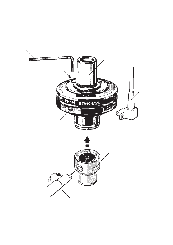
4 Operation
The autojoint is a highly repeatable coupling mechanism which will
minimise the need for tip re-qualifi cation after the exchange of probes
or extension bars. The locking mechanism is operated by rotating an
actuator contained in the mating half of the coupling, which is located
on the probe or extension bar. The actuator has a drive slot which
may be operated using an S10 joint key for manual probe or extension
bar changing applications (see fi gure 2 on page 8). Automatic probe
or extension bar changing is possible using the Renishaw ACR1 or
ACR3 autochange systems.
The status of the probe is indicated by the probe status LED. This is
normally lit when the probe is ready for use and extinguishes as the
probe triggers.
7
Page 10
8
Operation
Allen key
2.5 AF
M3 x 8 socket head
screws
(3 off)
Probe
status LED
Shank
Multiwire
probe
cable
Autojoint
adaptor
S10 joint key
Figure 2 - PH6M
Page 11

5 System connection
System connection
9
PI 7-2 interface PI 200 interface
PLM 38/42
D
PL47 + PL26
Probe:
TP2
TP20
TP200
SP25MTP7M PAA1
AC3
Abcd
2
AC
Efg
PLM 38/42
Figure 3 - System connection
Page 12

10
Interconnecting cables
6 Interconnecting cables
There is a choice of standard cables to connect from PH6M to probe
interfaces PI 7-2, PI 200, OPI6, the AC2 card for SP600M or the ACR3
card for SP25M.
Connectors shown in brackets are supplied in kit form. The cable
is supplied with the micro ‘D’ connector fi tted and the remote end
prepared, but unterminated, to facilitate assembly into machine looms.
Termination Length Ident
(15-way high
density ‘D’)
(15-way high
density ‘D’)
Unterminated 12 m PL56 A-1016-7626
(15-way high
density ‘D’)
(15-way high
density ‘D’)
(15-way high
density ‘D’)
Please contact Renishaw for details of cables for PI 200.
25 m PL38 A-1016-7625
15 m PL42 A-1016-7624
8 m PL44 A-1016-7627
3.7 m PL46 A-1016-7628
1.9 m PL45 A-1016-7629
Part
number
unterminated
unterminated
No connector
unterminated
unterminated
unterminated
Notes
Supplied
Supplied
supplied
Supplied
Supplied
Supplied
Page 13

7 Specifi cation
Specifi cation
11
Repeatability
Probe compatibility
Dimensions
Weight
Probe mount
Number of sockets
Style of probe joint
Probe status indication
Cable connection
1 µm (2σ) at stylus tip 50 mm (1.97 in)
from connector face.
Direct fi tting of SP25M, TP7M, OTP6M,
SP600M and TP6A.
PAA series adaptor/extension required for
M8 connector probes TP200, TP20 and
TP2.
Length: 40 mm (1.57 in) – without shank
Diameter: 60 mm (2.36 in)
160 g (0.36 lb)
Multiwired autojoint
One
Multiwired autojoint
One LED
15-way micro ‘D’ connector
Page 14

12
Probe compatibility
8 Probe compatibility
PH6M †
PAA
PEL1
PK1
PEL2
PAA2
PEL3
TP20
M2 thread
styli
TP2-5W
TP200‡*
PEL4
Q24885
PAA3
TP6
M3/M2
adaptor
Page 15

Probe compatibility
13
TP6A
M3 thread
styli
PEM25
PEM1
SP25M‡
PEM3 PEM25
PEM1
PEM2
SP600‡
D
TP7M‡
M4/M3
adaptor
M4 thread
styli
Page 16

14
Accessories and parts list
9 Accessories and parts list
9.1 Accessories
Part Description Part number
AM1 Adjustment module for precise alignment
of the head axes with the CMM or
autochange rack.
S10 Autojoint key A-1051-0040
9.2 Parts list
Please quote the part number when ordering.
Type Part number
PH6M + MS1 shank A-1074-0031
PH6M + MS2 shank A-1074-0032
PH6M + MS3 shank A-1074-0033
PH6M + MS9 shank A-1074-0039
PH6M + MS13 shank A-1074-0043
PH6M + MS15 shank A-1074-0045
A-1026-0320
Page 17

Renishaw plc
New Mills, Wotton-under-Edge,
Gloucestershire, GL12 8JR
United Kingdom
For worldwide contact details,
please visit our main website at
www.renishaw.com/contact
T +44 (0)1453 524524
F +44 (0)1453 524901
E uk@renishaw.com
www.renishaw.com
*H-1000-5001-03*
 Loading...