

Renishaw OSI, OMM-2C, OSI-D Installation Manual

OSI/OSI-D with OMM-2C multiple optical
probe interface system
Installation guide
H-5991-8504-03-A

Renishaw part no: H-5991-8504-03-A
First issued: 05.2017
Revised: 02.2019
© 2017–2019 Renishaw plc. All rights reserved.
This document may not be copied or reproduced
in whole or in part, or transferred to any other
media or language, by any means, without the
prior written permission of Renishaw plc.
The publication of material within this document
does not imply freedom from the patent rights of
Renishaw plc.

i
Contents
Before you begin .............................................................1.1
Before you begin
............................................................1.1
Disclaimer
..............................................................1.1
Trade marks
.............................................................1.1
Warranty
................................................................1.1
Changes to equipment
.....................................................1.1
CNC machines
...........................................................1.1
Care of the system components
.............................................1.1
Patents
.................................................................1.2
OSI EU declaration of conformity
...............................................1.3
OSI-D EU declaration of conformity
.............................................1.3
OMM-2C EU declaration of conformity
...........................................1.3
WEEE directive
.............................................................1.3
REACH regulation
...........................................................1.3
FCC information to user (USA only)
.............................................1.4
Safety
....................................................................1.5
OSI/OSI-D with OMM-2C basics ...............................................2.1
Introduction
................................................................2.1
OSI-D interface
...........................................................2.1
OSI/OSI-D inputs
............................................................2.2
OSI/OSI-D outputs
..........................................................2.2
OSI components
............................................................2.3
OSI-D components
..........................................................2.4
OMM-2C (A) connector (7-way/15-way)
........................................2.5
OMM-2C (B) connector (7-way)
..............................................2.5
Control connector block (15-way)
.............................................2.5
Switch SW1 output conguration
.............................................2.6
Switch SW2 output conguration
.............................................2.7
OSI/OSI-D input mode congurations
............................................2.8
Single probe mode
........................................................2.8
Multiple probe mode
.......................................................2.8

OSI/OSI-D with OMM-2C installation guide
ii
Contents
Switch-on / switch-off method ...............................................2.9
Start-up times ............................................................ 2.9
Synchronisation recovery ...................................................2.9
Multiple probe mode timing diagrams ........................................2.10
OSI/OSI-D output waveforms .................................................2.11
OSI/OSI-D dimensions ......................................................2.12
OSI/OSI-D specification .....................................................2.12
OMM-2C visual diagnostics – system status LEDs .................................2.13
START SIGNAL (blue, yellow, violet) .........................................2.14
ACTIVE SYSTEM (blue, yellow, violet) .......................................2.14
ERROR and STANDBY (red) ...............................................2.14
OVERCURRENT (ashing red) .............................................2.14
CORRUPTED SIGNAL (white) ..............................................2.14
OMM-2C dimensions ........................................................2.15
OMM-2C specification .......................................................2.15
OSI/OSI-D with OMM-2C system used in single probe mode .........................2.16
OSI/OSI-D with OMM-2C system used in multiple probe mode .......................2.17
System installation ...........................................................3.1
Typical OMM-2C system installation .............................................3.1
Introduction .............................................................3.1
Single conguration .......................................................3.1
Tandem conguration ......................................................3.2
OMM-2C application ......................................................3.3
OMM-2C cable ...........................................................3.3
Mounting the OSI/OSI-D to a DIN rail ............................................3.4
Performance envelope of OMM-2C with OMP600 or OMP60 ..........................3.5
Performance envelope of OMM-2C with OMP400, OMP40-2 or OLP40 ..................3.6
Performance envelope of OMM-2C with OTS ......................................3.7
Wiring diagram (with output groupings shown) .....................................3.8
Integral airblast installation (optional) ............................................3.9
Integral airblast application ..................................................3.9
Connecting and purging the air supply .........................................3.9
Maintenance .................................................................4.1
Maintenance ...............................................................4.1
Cleaning the interface .....................................................4.1
Removing the OMM-2C ....................................................4.2
Maintenance – air regulator unit ..............................................4.2

iii
Contents
Fault-finding .................................................................5.1
Parts list .....................................................................6.1

OSI/OSI-D with OMM-2C installation guide
iv
Contents
This page is intentionally left blank.

1.1
Before you begin
Before you begin
Disclaimer
RENISHAW HAS MADE CONSIDERABLE
EFFORTS TO ENSURE THE CONTENT OF THIS
DOCUMENT IS CORRECT AT THE DATE OF
PUBLICATION BUT MAKES NO WARRANTIES
OR REPRESENTATIONS REGARDING
THE CONTENT. RENISHAW EXCLUDES
LIABILITY, HOWSOEVER ARISING, FOR ANY
INACCURACIES IN THIS DOCUMENT.
Trade marks
RENISHAW and the probe symbol used in the
RENISHAW logo are registered trade marks of
Renishaw plc in the United Kingdom and other
countries. apply innovation and names and
designations of other Renishaw products and
technologies are trade marks of Renishaw plc or
its subsidiaries.
All other brand names and product names used
in this document are trade names, trade marks, or
registered trade marks of their respective owners.
Warranty
Equipment requiring attention under warranty
must be returned to your equipment supplier.
Unless otherwise specifically agreed in writing
between you and Renishaw, if you purchased
the equipment from a Renishaw company, the
warranty provisions contained in Renishaw’s
CONDITIONS OF SALE apply. You should consult
these conditions in order to find out the details
of your warranty but, in summary, the main
exclusions from the warranty are if the equipment
has been:
• neglected, mishandled or inappropriately used;
or
• modified or altered in any way except with the
prior written agreement of Renishaw.
If you purchased the equipment from any other
supplier, you should contact them to find out what
repairs are covered by their warranty.
Changes to equipment
Renishaw reserves the right to change equipment
specifications without notice.
CNC machines
CNC machine tools must always be operated by
fully trained personnel in accordance with the
manufacturer's instructions.
Care of the system components
Keep system components clean and treat with
care. Do not apply labels to the front of the
OMM-2C or otherwise obstruct the window.

OSI/OSI-D with OMM-2C installation guide
1.2
Before you begin
EP 0974208
EP 1503524
JP 4294101
US 6839563
Patents
Features of OMM-2C and OSI/OSI-D (and
features of similar products) are the subject of
one or more of the following patents and/or patent
applications:

1.3
Before you begin
C
OSI EU declaration of conformity
Renishaw plc declares under its sole responsibility
that the OSI is in conformity with all relevant
Union legislation.
The full text of the EU declaration of conformity is
available at:
www.renishaw.com/mtpdoc
OSI-D EU declaration of
conformity
Renishaw plc declares under its sole responsibility
that the OSI-D is in conformity with all relevant
Union legislation.
The full text of the EU declaration of conformity is
available at:
www.renishaw.com/mtpdoc
OMM-2C EU declaration of
conformity
Renishaw plc declares under its sole responsibility
that the OMM-2C is in conformity with all relevant
Union legislation.
The full text of the EU declaration of conformity is
available at:
www.renishaw.com/mtpdoc
C
WEEE directive
The use of this symbol on Renishaw products
and/or accompanying documentation indicates
that the product should not be mixed with
general household waste upon disposal. It is the
responsibility of the end user to dispose of this
product at a designated collection point for waste
electrical and electronic equipment (WEEE) to
enable reuse or recycling. Correct disposal of
this product will help to save valuable resources
and prevent potential negative effects on the
environment. For more information, please contact
your local waste disposal service or Renishaw
distributor.
REACH regulation
Information required by Article 33(1) of Regulation
(EC) No. 1907/2006 (“REACH”) relating to
products containing substances of very high
concern (SVHCs) is available at:
www.renishaw.com/REACH
C

OSI/OSI-D with OMM-2C installation guide
1.4
Before you begin
FCC information to user (USA
only)
47 CFR Section 15.19
This device complies with part 15 of the FCC
Rules. Operation is subject to the following two
conditions:
1. This device may not cause harmful
interference, and
2. This device must accept any interference
received, including interference that may
cause undesired operation.
47 CFR Section 15.21
The user is cautioned that any changes or
modifications not expressly approved by
Renishaw plc or authorised representative could
void the user’s authority to operate the equipment.
47 CFR Section 15.105
This equipment has been tested and found to
comply with the limits for a Class A digital device,
pursuant to part 15 of the FCC Rules. These limits
are designed to provide reasonable protection
against harmful interference when the equipment
is operated in a commercial environment. This
equipment generates, uses, and can radiate
radio frequency energy and, if not installed
and used in accordance with the instruction
manual, may cause harmful interference to radio
communications. Operation of this equipment
in a residential area is likely to cause harmful
interference in which case the user will be
required to correct the interference at his own
expense.

1.5
Before you begin
Safety
Information to the user
In all applications involving the use of machine
tools or CMMs, eye protection is recommended.
The OMM-2C has a glass window. Handle with
care if broken to avoid injury.
Information to the machine supplier/
installer
It is the machine supplier's responsibility to
ensure that the user is made aware of any
hazards involved during operation, including those
mentioned in Renishaw product literature, and to
ensure that adequate guards and safety interlocks
are provided.
Under certain circumstances, the probe signal
may falsely indicate a probe seated condition. Do
not rely on probe signals to halt the movement of
the machine.
Information to the equipment installer
All Renishaw equipment is designed to comply
with the relevant EU and FCC regulatory
requirements. It is the responsibility of the
equipment installer to ensure that the following
guidelines are adhered to, in order for the product
to function in accordance with these regulations:
• any interface MUST be installed in a position
away from any potential sources of electrical
noise, i.e. power transformers, servo drives etc;
• all 0V/ground connections should be
connected to the machine “star point” (the “star
point” is a single point return for all equipment
ground and screen cables). This is very
important, and failure to adhere to this can
cause a potential difference between grounds;
• all screens must be connected as outlined in
the user instructions;
• cables must not be routed alongside high-
current sources, i.e. motor power supply cables
etc, or be near high-speed data lines;
• cable lengths should always be kept to a
minimum.
• the dc supply to this equipment must be
derived from a source which is approved to
IEC/BS/EN 60950-1.
Equipment operation
If this equipment is used in a manner not specified
by the manufacturer, the protection provided by
the equipment may be impaired.
Optical safety
This product contains LEDs that emit both visible
and invisible light.
OMM-2C is ranked Risk Group: Exempt (safe by
design).
The product was evaluated and classified using
the following standard:
BS EN 62471:2008 The photobiological
(IEC 62471:2006) safety of lamps and lamp
systems.
Renishaw recommends that you do not stare at or
look directly into any LED device, irrespective of
its risk classification.

OSI/OSI-D with OMM-2C installation guide
1.6
Before you begin
This page is intentionally left blank.

2.1
Introduction
CNC machine tools using Renishaw spindle
probes with optical signal transmission for
workpiece inspection, or tool setters with optical
signal transmission, require an interface system
to convert the signals from the probe into
voltage-free solid state relay (SSR) outputs for
transmission to the CNC machine controller.
Typically installed within the CNC machine
controller’s cabinet and located away from
sources of interference such as transformers and
motor controls, the OSI can draw its power from
the machine’s nominal 12 Vdc to 30 Vdc supply.
The OSI has an input voltage range of 12 Vdc to
30 Vdc. The supply is protected by a 1.1 A selfresetting fuse (the current, when connected to
an OMM-2C, is either 400mA max. @ 12 V or
200 mA max. @ 24 V with tandem OMM-2C). To
reset the fuse, remove the power then identify and
rectify the cause of the fault.
The OSI can be used with either a single or
tandem OMM-2C configuration, housed within
the machining environment. The OMM-2C is
an optical receiver designed for fitment in the
machine spindle. It transmits control signals to the
spindle probe or tool setter, and receives probe
data signals for onward transmission to the OSI
and CNC controller. Power is supplied from the
OSI interface. Visual indication of system status is
provided via the LEDs located on the OMM-2C.
The OSI with OMM-2C system operates using
a ‘modulated’ optical transmission mode and is
compatible with machine probes that also operate
in ‘modulated’ mode.
When in operation, the OMM-2C displays its
present status via three multi-coloured LEDs
located behind the front window (see “OMM-2C
visual dignostics – system status LEDs” on page
2.12).
OSI/OSI-D with OMM-2C basics
OSI-D interface
The OSI-D interface is a variant of the standard
OSI interface, and has been designed for easy
installation to CNC machine controllers using a
15-way HD D type connector for probe input.
The OSI-D interface shares all functionality
and wiring connections with the standard OSI
interface, the only difference being the OMM-2C
connector (A).
NOTE: Throughout this installation guide, the term
OSI and any OSI images refers to both OSI or
OSI-D, unless otherwise specied.

OSI/OSI-D with OMM-2C installation guide
2.2
OMM-2C basics
OSI/OSI-D inputs
There are three inputs:
• Probe 1 start
• Probe 2 start
• Probe 3 start
Switch SW2 can be configured to accept either
a pulsed output or level output from the machine
control.
Probe 1 start
Level 8 V to 30 V (4 mA @ 15 V, 7 mA @ 24 V)
When the input is active, the probe is
switched on.
Pulsed 8 V to 30 V (4 mA @ 15 V, 7 mA @ 24 V)
The probe toggles between being
switched on and off. The minimum pulse
width is 10ms.
Probe 2 and probe 3 start
Level 10 V to 30 V (10 mA @ 24 V)
When the input is active, the probe is
switched on.
Pulsed 10 V to 30 V (10 mA @ 24 V)
The probe toggles between being
switched on and off. The minimum pulse
width is 10ms.
The OSI uses level and pulsed machine inputs to
define the active probe. When the respective input
is active, the probe is switched on.
If all inputs are simultaneously active, the system
will default to error.
OSI/OSI-D outputs
There are four outputs:
• Probe status 1 (SSR)
• Probe status 2 (SSR)
• Error (SSR)
• Low battery (SSR)
All outputs can be inverted by using switch SW1,
(see “Switch SW1 output conguration” on page
2.5).
Probe status 1, Error, Low battery (SSR):
• ‘On’ resistance = 50 W max.
• Load voltage = 40 V max.
• Load current = 100 mA max.
Switching times (with 10 mA load)
• Open to closed = 100 µs max.
• Closed to open = 25 µs max.
Both probe status outputs indicate the status
of the selected probe (only one probe can be
selected at a time). They are both individually
configurable.
The OMM-2C LEDs will start flashing red when an
output overload has occurred. Probe status output
will be triggered (SSR open). If this occurs, turn
off the power supply and remove the source of the
problem. Turning on the power supply will reset
the OSI.
CAUTIONS:
Power supply voltage
Do not exceed 30 V between the following:
• the 0 V and the screen wire;
• the 12 V to 30 V supply wire and screen wire;
• the 12 V to 30 V supply wire and 0V wires.
This could result in permanent damage to the
OSI, OMM-2C and/or the power supply.
The use of in-line fuses at the machine cabinet
end is recommended to provide protection for the
OSI, OMM-2C and cable.
Screen connection
A good connection must be made to the machine
ground (‘star point’).
Output
Ensure the output from the OSI does not exceed
the specied current ratings.
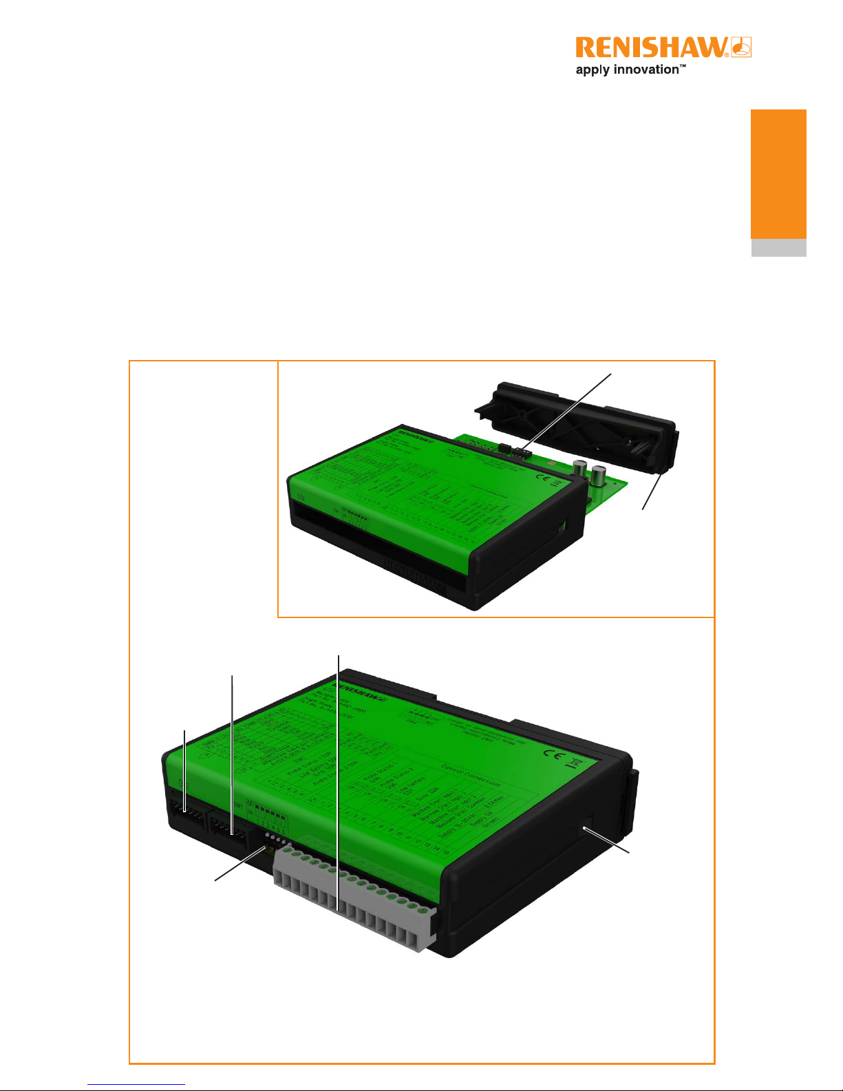
OSI components
The following components are housed within
the front face of the OSI (as shown in the figure
below):
• OMM-2C (A) connector (7-way);
• OMM-2C (B) connector (7-way);
• Control connector block (15-way);
• SSR configuration switch SW1.
OMM-2C (A)
connector
(7-way)
Control connector
block (15-way)
OMM-2C (B)
connector
(7-way)
SSR configuration
switch SW1
Cover tab –
depress to
remove cover
The following components are housed within the
body of the OSI:
• Mode configuration switch SW2.
Access to switch SW1 and switch SW2 is required
during installation only.
Mode configuration
switch SW2
Removable cover
(used to access SW2)
2.3
OMM-2C basics
OSI-D components
The following components are housed within the
front face of the OSI-D (as shown in the figure
below):
• OMM-2C (A) connector (15-way HD D type);
• OMM-2C (B) connector (7-way);
• Control connector block (15-way);
OMM-2C (A)
connector
(15-way HD D type)
Control connector
block (15-way)
OMM-2C (B)
connector
(7-way)
Cover tab –
depress to
remove cover
The following components are housed within the
body of the OSI-D:
• SSR configuration switch SW1.
• Mode configuration switch SW2.
Access to switch SW1 and switch SW2 is required
during installation only.
Mode configuration
switches SW1 and SW2
Removable cover
(used to access SW1
and SW2)
OSI/OSI-D with OMM-2C installation guide
2.4
OMM-2C basics
 Loading...